Task 2: Write a Program
Let’s break down this week’s assignment
- Write a program for a microcontroller development board that you made - Quentorres Board from Week 4
- to interact (with local input &/or output devices) - This is arbitrary. I chose to do a simple Button (Input) LED Diode (Output) Interaction
- communicate (with remote wired or wireless devices)
At the time of writing this down… I am still in the progress of milling my new QuenTorres Board. So I thought my line of working this week would have to be
- Simulate Quentorres Board
- Programming
- Embed the program into the freshly milled and stufffed Quentorres Board.
Simulating Quentorres Board in Wokwi
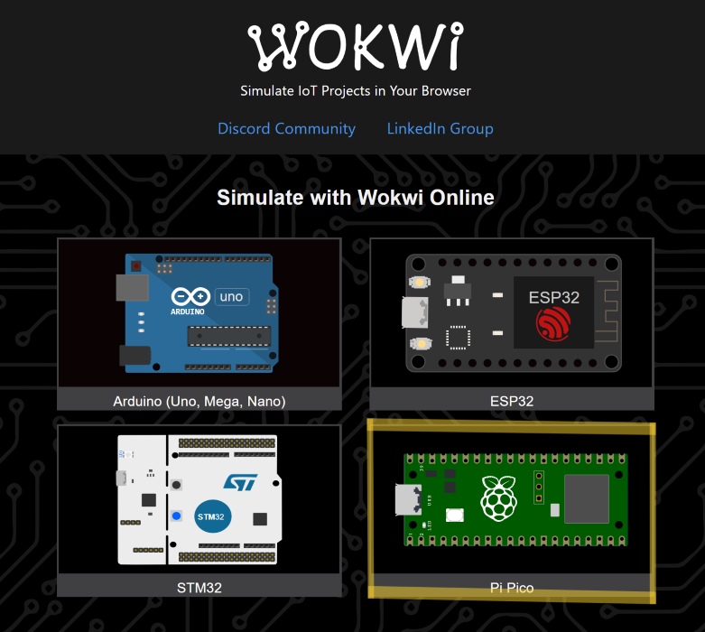
To head start first as I am still having problems with producing my Quentorres board, I thought I will simulate the board first in Wokwi. The XIAO RP2040 is a microcontroller that is powered by the Raspberry Pi 2040 chip. It is an alternative to the Pi Pico - differences are the XIAO has lesser GPIO (general-purpose input/output) pins. So in Wokwi - I chose the Pi Pico to simulate the XIAO micro controller.
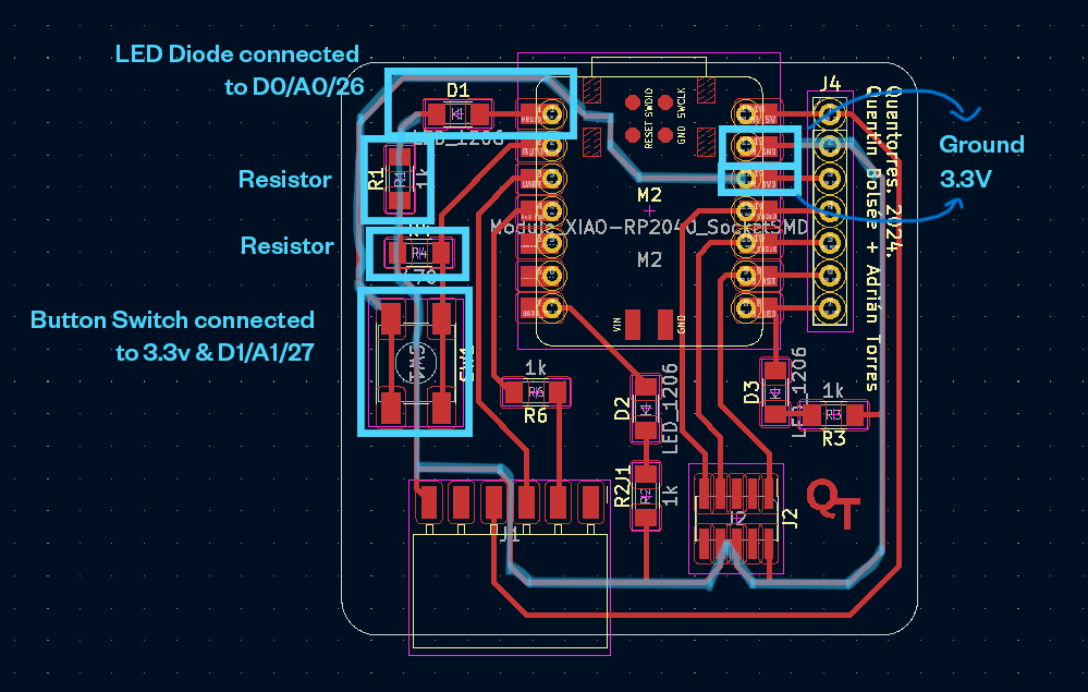
Firstly. I look at the schematics of the Quentorres board - to figure out the placement of the components in my simulated board
Then I compare the XIAO board and the Pi Pico to figure out the right GPIO configuration and connections.
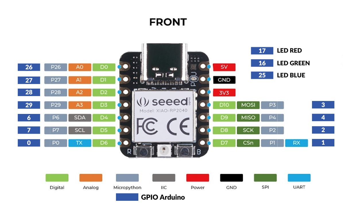
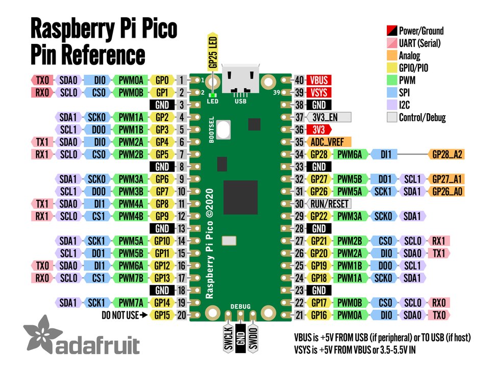
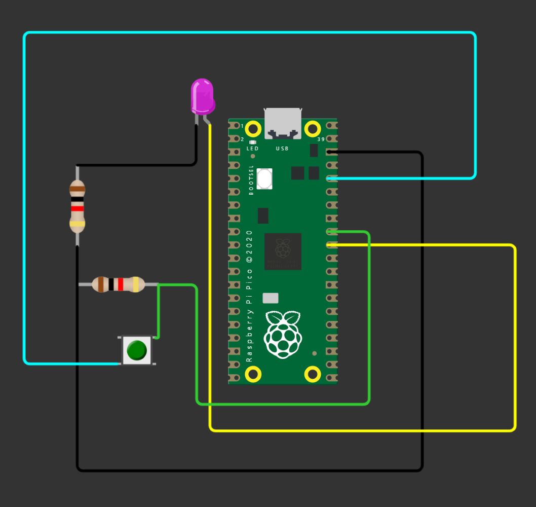
To compare is important. In XIAO, the LED & Switch is at D0,D1 - but as we see in the Pi Pico, GPIO 0 & 1 has functions reserved for the UART(universal asynchronous receiver-transmitter) interface. So instead, I connect with the GPIO Arduino Value if the XIAO controller into the Pi Pico- LED at 26, Button Switch at 27 (but I reckon any GPIO output works s long it is not reserved for special functions....).
The simulated board and components looks like this
Programming
// UNDERSTANDING THE LAYERS OF PROGRAMMING WITH ARDUINO IDE (C/C++) //
- Libraries: code that have been developed for specific purpose - packaged for specifically working with particular hardwares or functions.
- Variables: A variable is a place to store a piece of data. It has a name, a value, and a type. Think of it like a container that has all the particular tools needed (declared) to make your code runs. Structure is usually Type Name = Value
- Function
- Set up: code to run once in the start/set up
- loop: main code function that runs repeatedly
- Control Structure: order in which individual statements, instructions or function calls of an imperative program are executed or evaluated.
Watch more from here:
Before we start coding… it is always good to break down how we envision the code to function. For this week’s assignment in my case… since there is a component of communication… I want to make a grumpy LED light that doesn’t want to be disturbed. I see the functions as following
Pressing the Switch
- Board tells me in the beginning “DO NOT PRESS”
- If button is pressed
- LED light turns on
- Board responds back with “TURN ME OFF” based on the lightstate ON
- If button is pressed again
- LED light turns off
- Board responds with “THANK YOU. DO NOT PRESS” when the state of light is OFF
Sending command
- Board tells me in the beginning “DO NOT PRESS”
- If I type a command and send
- LED light turns on
- Board responds back with “TURN ME OFF”
- I type a command and send again
- LED light turns off
- Board responds with “THANK YOU. DO NOT PRESS” when the state of light is OFF
This are my lines of code, inspired by this tutorial
//Define the pin numbers for LED & Button Switch
const int ledPin = 26; //Based on the Arduino GPIO Pin of RP2040
const int swPin = 27; //Based on the Arduino GPIO Pin of RP2040

//Define variable to keep track of the state of LED (ON or OFF).
bool lightState = false;
//LED default state is OFF
//Boolean because there are two states ON (HIGH,TRUE,1) or OFF(LOW,FALSE,0)

void setup() {

  //Button is Input, LED is Output
  pinMode(ledPin, OUTPUT);
  pinMode(swPin, INPUT);

  Serial.begin(9600);
  Serial.setTimeout(10);
  Serial.println("DO NOT PRESS");
// For Communication Mode. Serial communication is initialized on Serial with a baud rate of 9600, and a timeout of 10 milliseconds.
// The board starts with "Do Not Press".
// You can pull up the Serial Monitor in ArduinoIDE to do Serial Communication
}

void loop() {

 // Check if there is data available
  if (Serial.available() > 0) {
  // Read the incoming data - which is in the form of message so - String
    String s = Serial.readString();
    Serial.print("YOU: ");
    Serial.println(s);

    // When array is received, the LED light toggles (ON or OFF)
    lightState = !lightState;

    // Update the LED
    digitalWrite(ledPin, lightState);

    // if LED light is ON, board communicates with "turn me off". If turned OFF "thank you. do not press"
    if (lightState == HIGH) {
      Serial.println("TURN ME OFF");
    } else {
      Serial.println("THANK YOU. DO NOT PRESS");
    }

  }
  // Check if Button is pressed
  if (digitalRead(swPin) == HIGH) {

      // When button is pressed, the LED light toggles (ON or OFF)
      lightState = !lightState;

      // Update the LED
      digitalWrite(ledPin,lightState);
      delay (250);

    // if LED light is ON, board communicates with "turn me off". If turned OFF "thank you. do not press"
    if (lightState == HIGH) {
      Serial.println("TURN ME OFF");
    } else {
      Serial.println("THANK YOU. DO NOT PRESS");
    }

}
Embedding the Program into the Quentorres Board
Interact
When I press the button, the light turns on - but the board will ask to turn off and to not press, so if you press once again it will turn off.
When I type a command, the LED light will turn on and typing another command will turn the LED off