Task 3: Parametric Press-Fit Construction Kit
Let’s get some definitions out of the way
-
Parametric Design: design method in which features, such as building elements and engineering components, are shaped based on algorithmic processes rather than direct manipulation. In this approach, parameters and rules establish the relationship between design intent and design response
-
Press-Fit: where a physical object is forced into a slightly smaller opening, a form of fastening between two tightfitting mating parts that produces a joint which is held together by friction after the parts are pushed together.
I am interested in exploring how simple shapes with parametric press-fit slots; when combined, can make interesting architectural patterns and dynamic forms. And the key is to design with modularity and patterns. One of the architects that I look up to, KENGO KUMA, has several work that displays beautiful layering of modular patterns like the following:
- Botanical Pavillion which I get to see in person!
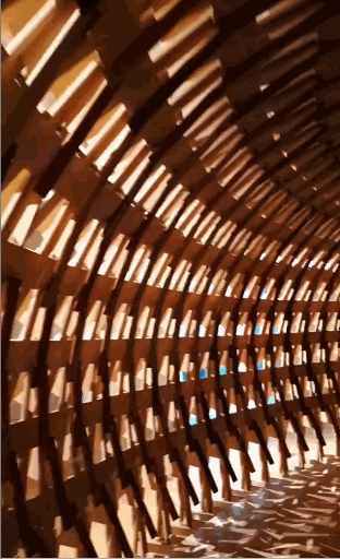
- Kodama Pavillion this uses press-fit!
Inspiration
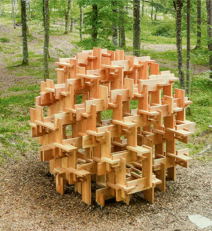
So I started looking into some projects that could be easy enough for me to do and found the project Pixel Wall by Rodrigo Garcia Alvarado, Underlea Bruscato, Oscar Otarola, Karina Morales.
![]()
![]()
![]()
With the limited amount of cardboards we have… I decided to appropriate this design for a 2.7mm cardboard and way smaller model.
Parametric Design with Fusion 360
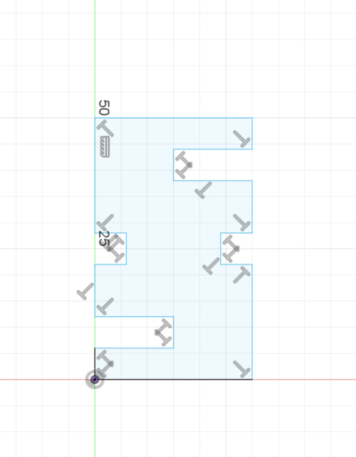
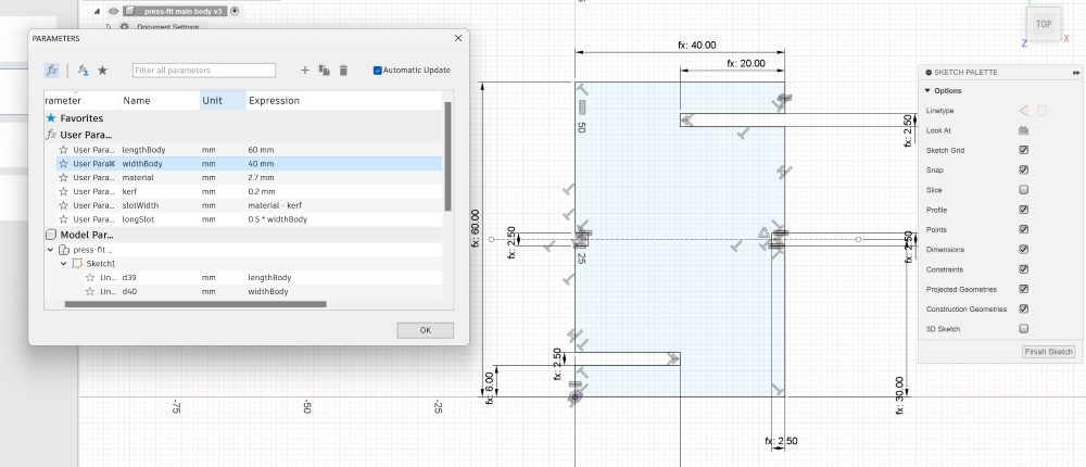
- In Sketch Mode, start designing with lines. Don’t worry if it doesn’t look too accurate…
- Click
Modify>Change Parameter. Make sure that you account your material thickness and kerf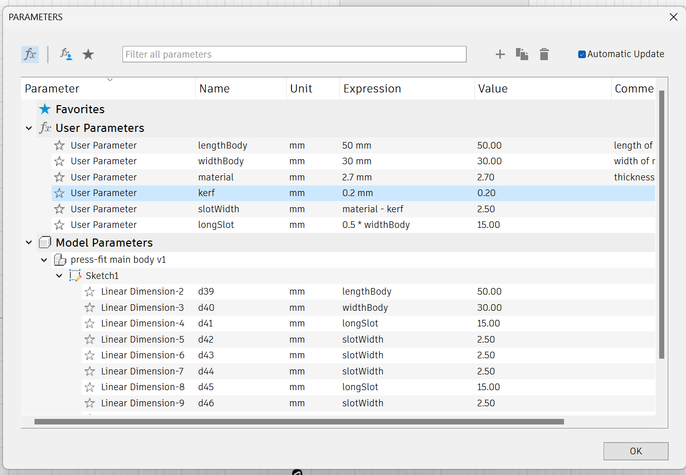
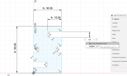
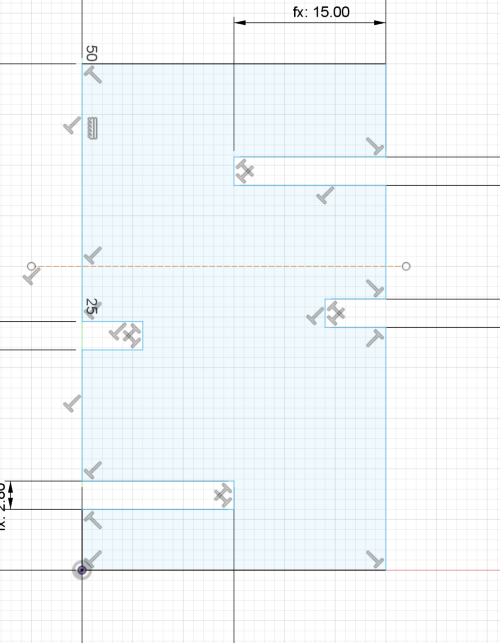
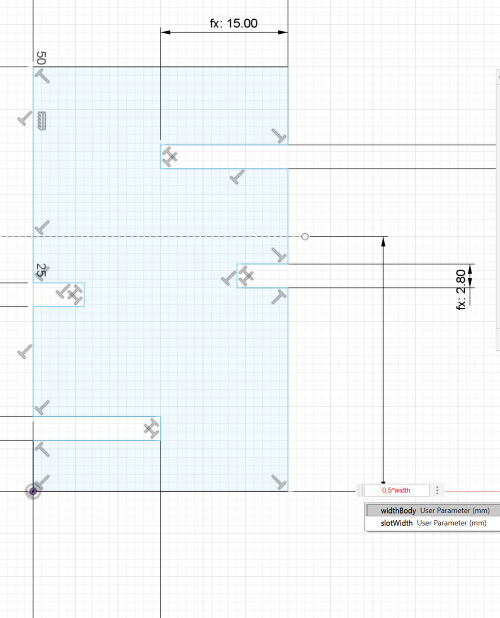
- Once you have list down your parameters, start changing the length/width of your sketch with the parameters you have list down. For the deep slot, I based it on half of the width of the shape (0.5*widthBody) and for the middle lot based on kerf which is (0.2mm)
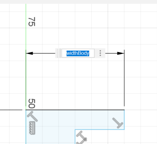
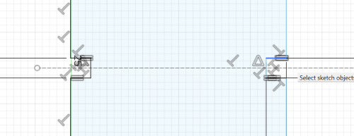
- To make sure that the slots are placed rightfully, I use the help of
construction line. I am using the construction line to guide me with finding the mid-point of the shape (the dashed line)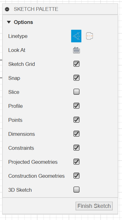
- In the Constraint Tab Choose
Midpointto adjust the slots to the construction line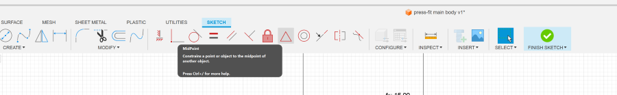
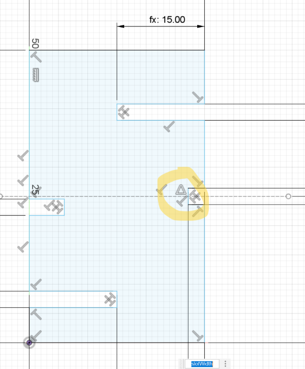
- Make sure that the opposite slot are also set as equal. You can go to the choose
Equalin the Constraint tab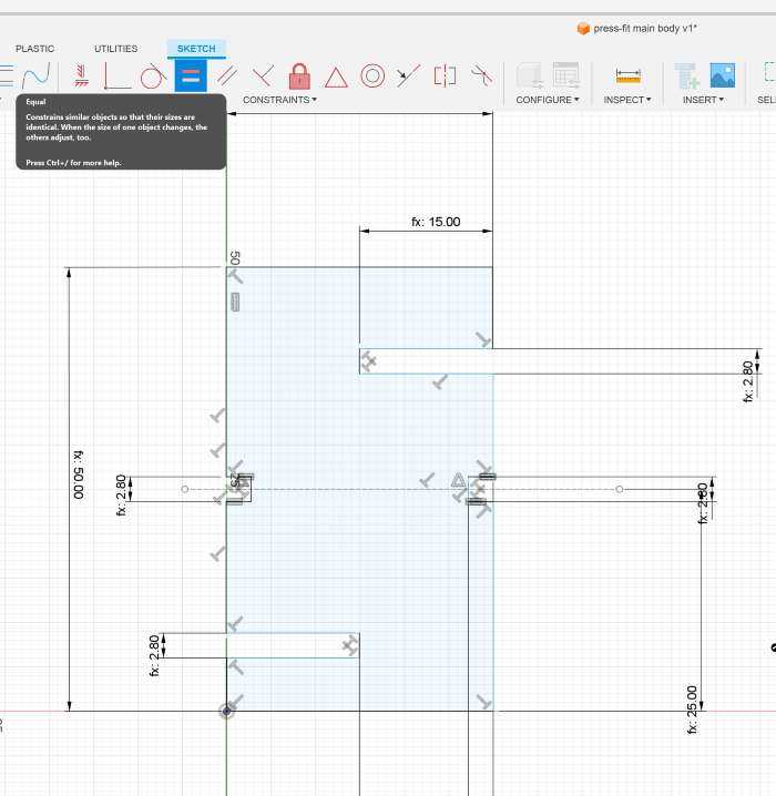
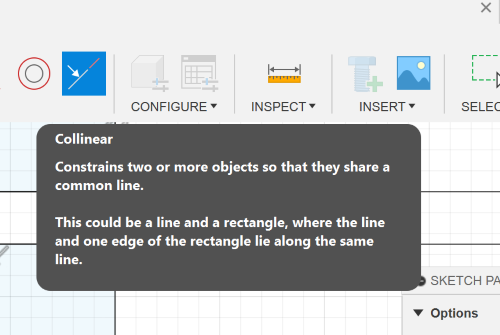
- Finally constraint everything else that hasn’t been constrained. In this shape the remaining will be the length in between the slot. I set the parameter of the length, Equal any similar lengths and then use the
Colinearfunction to constraint the rest.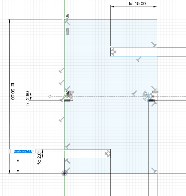
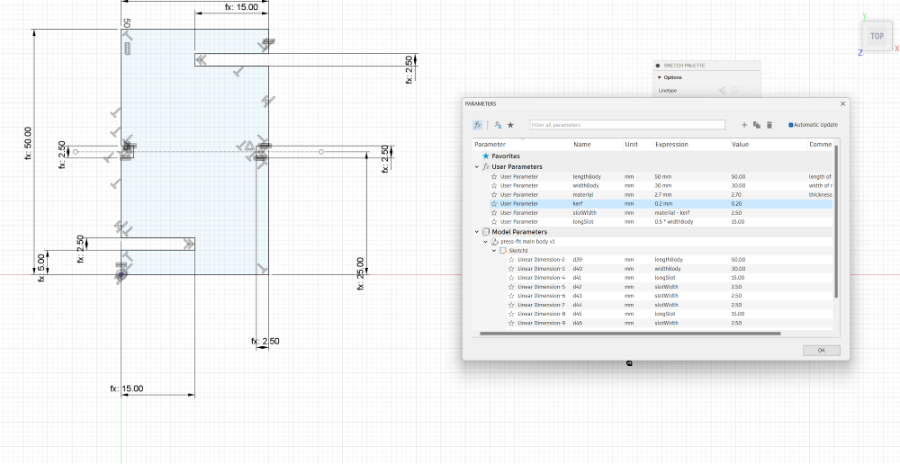
The neat thing about parametric design is when you change the length and width - these parameters would adapt and proportionately scale to your changes.
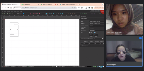
Laser Cut
Remote laser cutting thanks to Tafia’s help.
Spiral 1
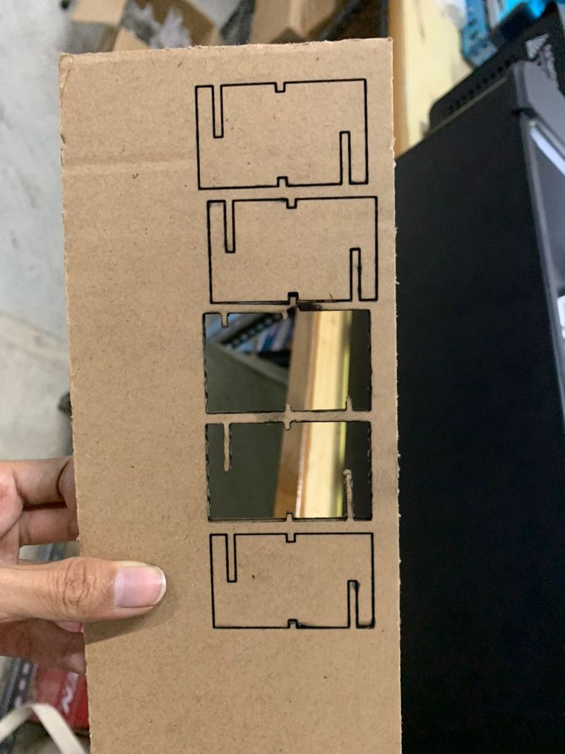
Cutting the Parts
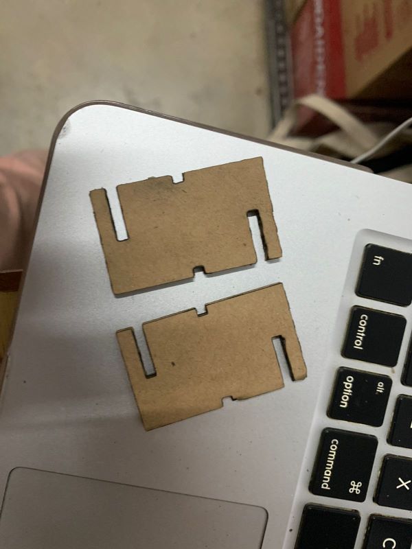
Assembling
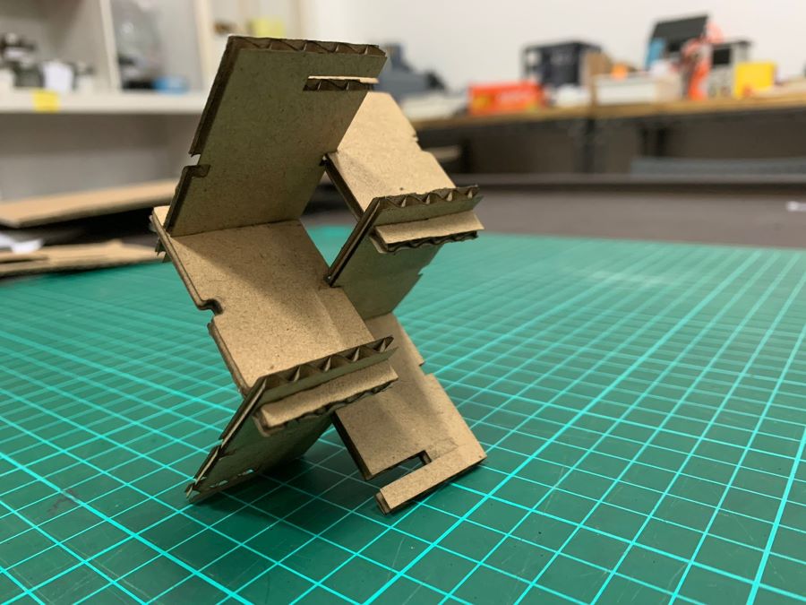
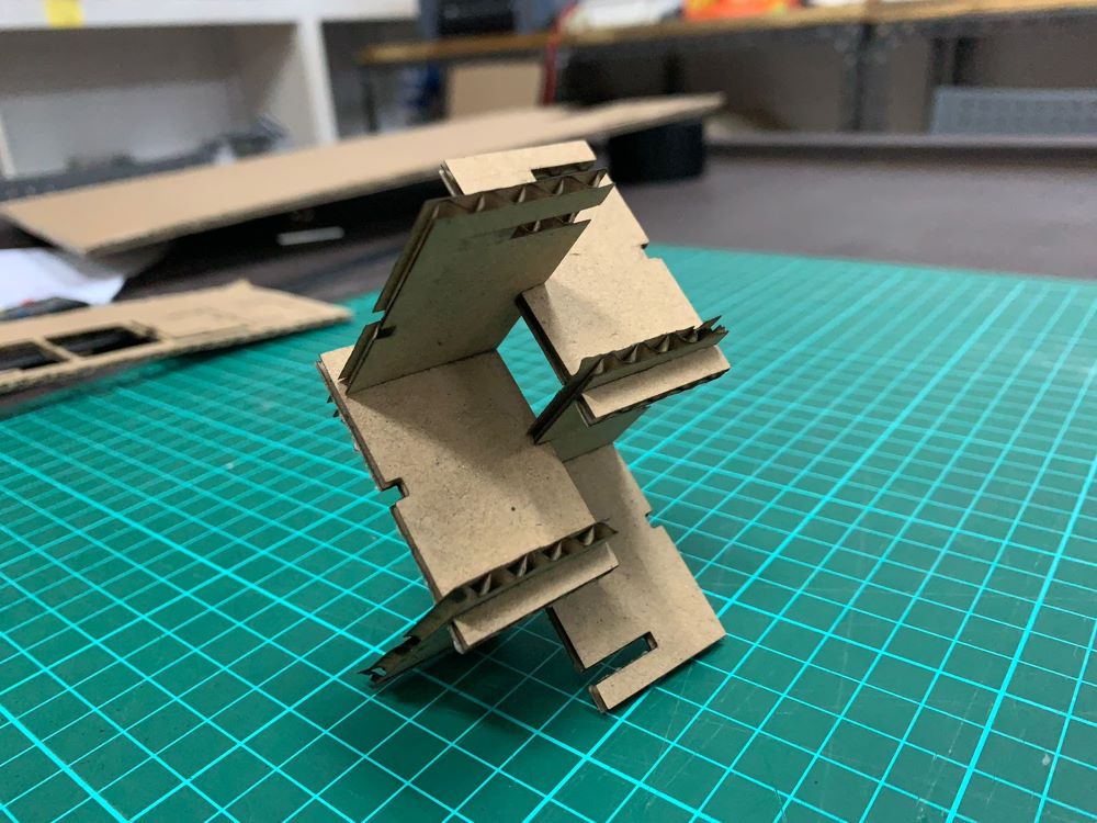
 The slot fits each other nicely and is very snugged… but the edges need to be chamfered so that fitting will be smoother. I will chamfer them when I come back to Bali - for Spiral 2 reiteration.
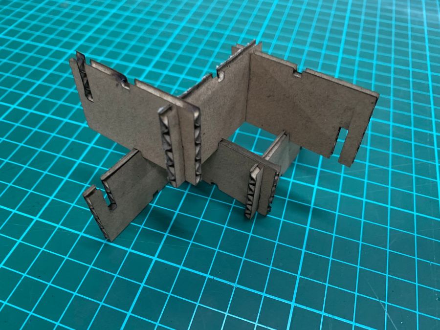
Updates on Spiral 1
The modularity of the design is there… but I was only able to create small structures..... Ideally the edges should be chamfered. As I was shaping and reshaping structures with the laser-cut parts, the 90 degree-edges were causing wear and tear effect very easily on the cardboard material and was especially notable with the middle gap being very shallow. The middle gap of the laser-cut parts went through the most material stress, hence as I get to shaping bigger and more complex the structure - it just starts to fall apart.
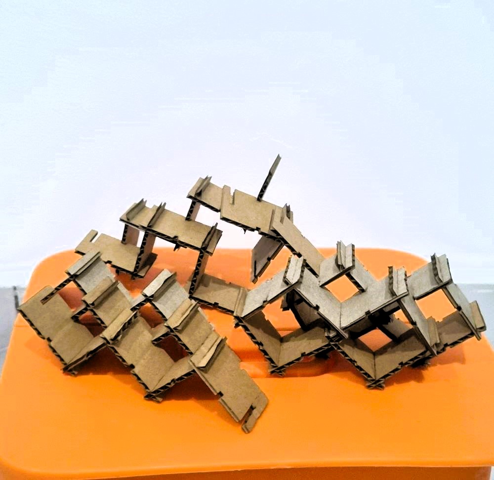
So to keep in mind for the next design update:
- Chamfer is Important
- Make the middle gap deeper