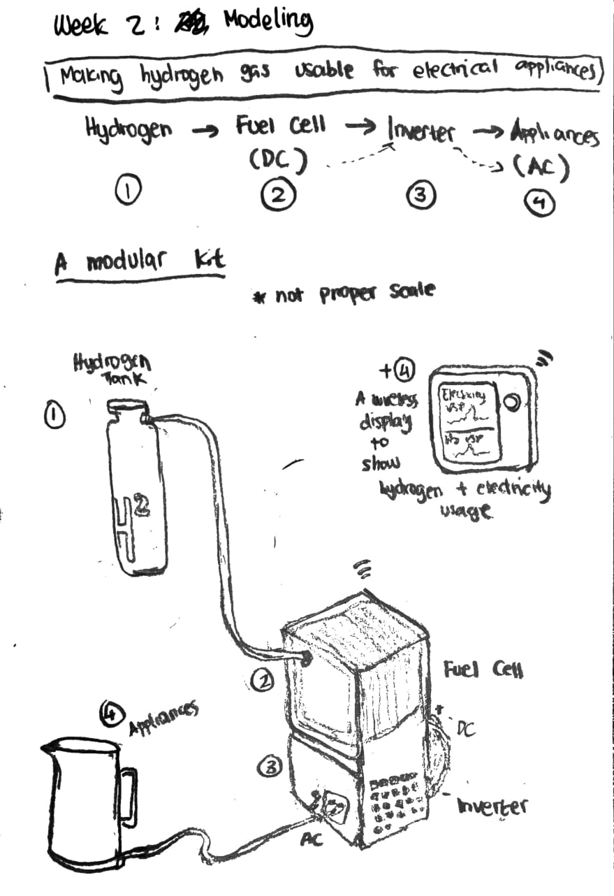
Task 1: Model a possible Final Project
This week’s assignment we are told to visualise and model our final projects. To do that we can utilise both 2D & 3D Modeling Softwares to virtually conjure a concept before we start the making process!
2D Design
Raster
Raster files are images build with grid of individual pixels - tiny squares that makes up an image file. Each pixel contains information about its color, and when you zoom in on a raster image, you see these individual pixels. More pixels = higher image quality. Most digital images are in raster file. In this case, a photograph of my final project sketch taken from my phone can be considered a raster file.
Vector
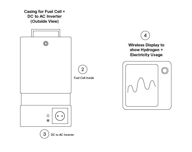
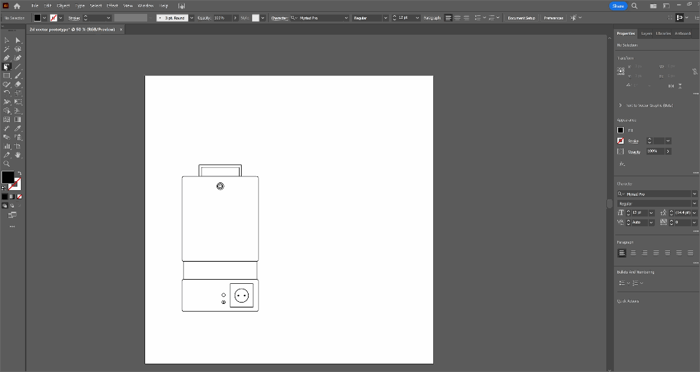
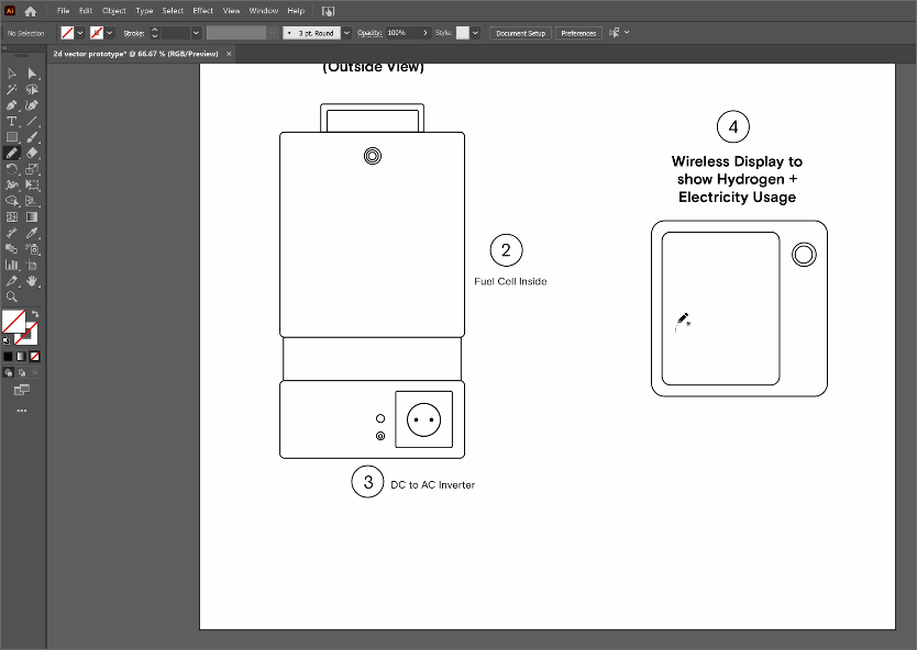
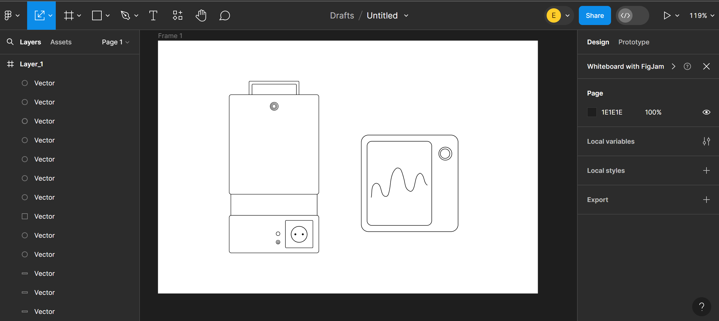
Vector graphics are type of images that use mathematical equations to create shapes, lines, curves that passes through points. Think of it like plotting points on a graph and connecting them with lines to form shapes. These shapes can be resized or scaled without losing quality because the computer can recalculate the mathematical equations to fit the new size, without getting pixelated, making it ideal for logos, icons, and illustrations where you might need to change the size without sacrificing image quality. Here is an example of a vector graphic of the 2nd, 3rd and 4th component of my idea.
A Walkthrough of Adobe Illustrator to make your own 2D Vector Graphics good enough to be considered for an Ikea Assembly Guide Book
I would recommend championing open-source softwares like Inkscape but because I needed to complete this week assignment fast, I decided to use Illustrator. Illustrator is convenient but boy oh boy.... it’s expensive.... For a simple Vector Graphics that I did above… you can also use Figma. It is UI/UX-friendly and has smaller learning curve than Illustrator. Figma is an industry standard for Digital Product Design and you can collaborate with many users on one file. However it is not as powerful as Illustrator. Illustrator has amazing functions that allow you to create intricate and detailed illustrations. For example, I was able to create the following illustrations merely just with Adobe Illustrator.
Okay enough of the flex.... We are not doing a tutorial of the image above. We will be creating a simple 2D Vector Graphics - good enough to be considered as potential vectors for an Ikea Assembly Guide (lol). Here is a walkthrough of how to do it in Illustrator (but because it is so simple to create, use the same design logic on your preferred software)
- Open your Adobe Illustrator program. This is what you need to understand about your workspace.
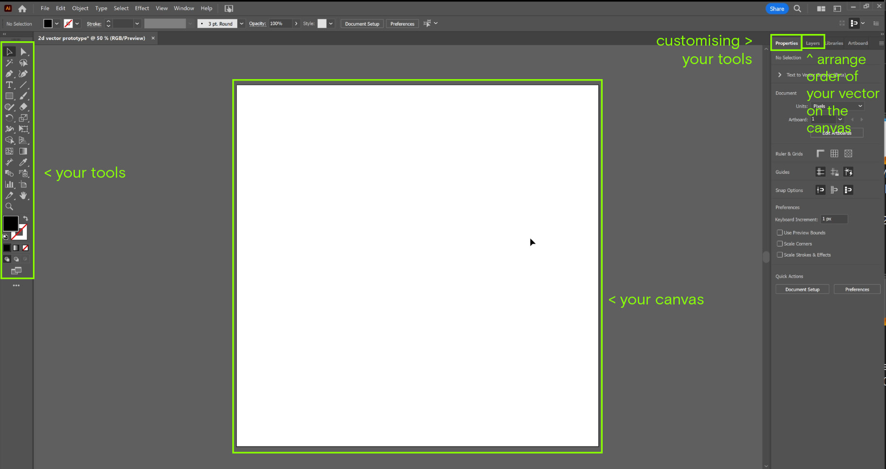
- From the Tools, pick the “Rectangular” icon to create your vector shape.
- In Illustrator you can easily swap “Fill (Area)” and “Stroke” (Perimeter). Change the thickness of your line/stroke at the Stroke Options. Thinner Lines <1pt, Thicker Lines> 1pt.
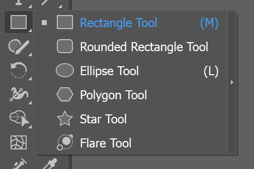
- If you right click on the rectangular icon, you can get more shapes
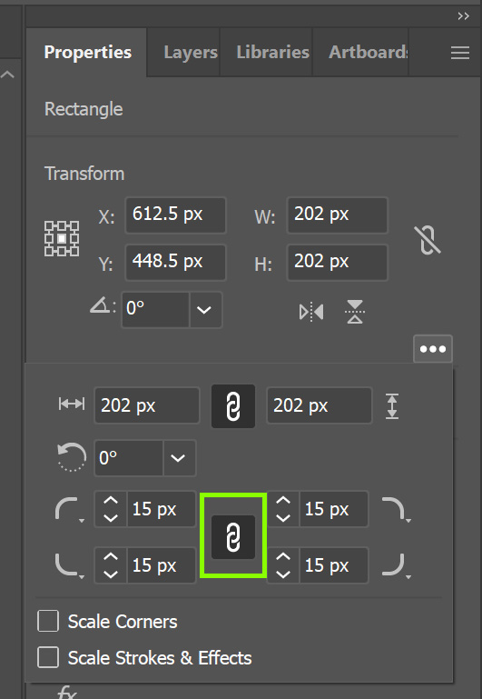
- You can create rounded corner for your established shape in the “Properties” Tab. Click the “Chain” icon if you want your shape to be transformed proportionately.
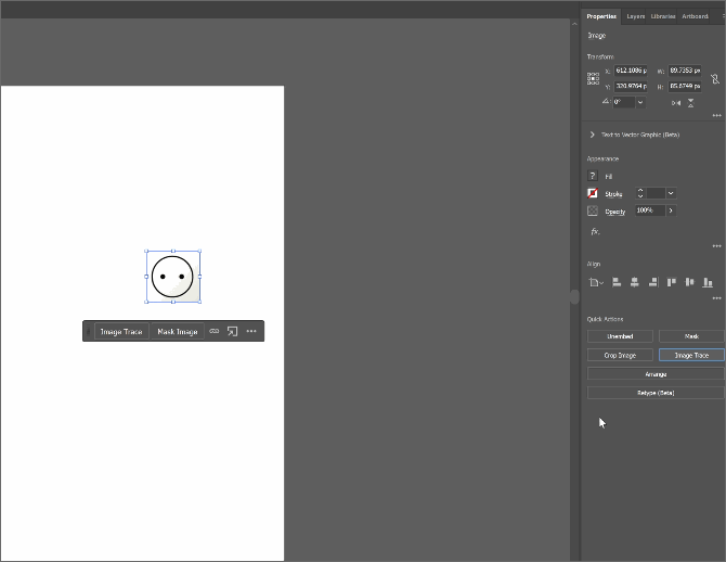
- Turn a sample raster image to vector with Bitmap Tracing.
- Add Text for some headlines / descriptions
- Try playing around with the Pen/Pencil option to further emphasize and prove how Vectors essentialy work.
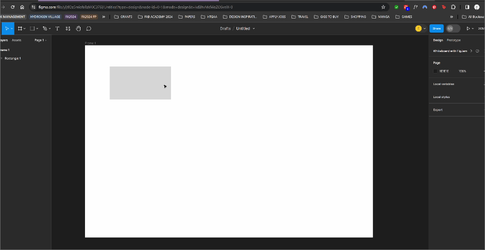
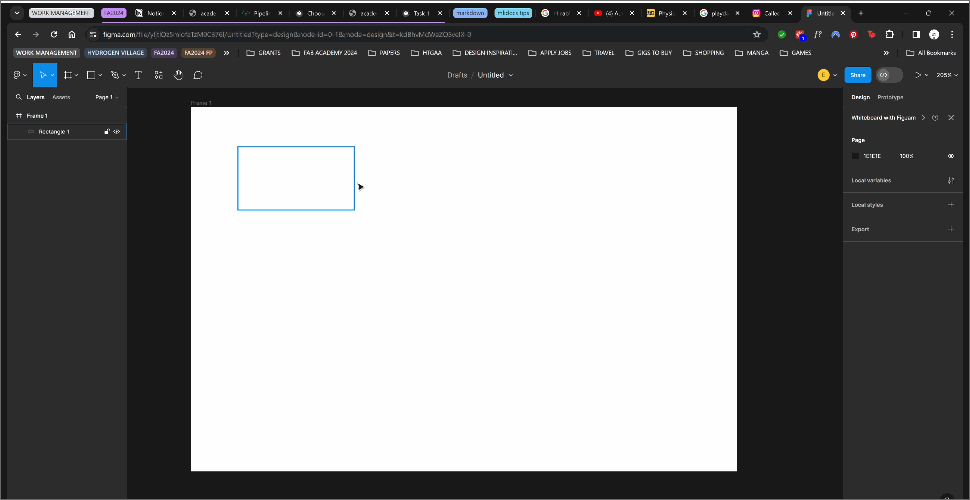
Figma
Figma is a collaborative web application for interface design.
- Interface - Pretty Straightforward
 - Make a rectangle, stroke and fill
 - Cornered Rectangles & Resizing
 - Different Vector Shapes
Putting 2 and 2 together
3D Design
For this section I am utilising on my free 1 year Fusion 360 Subscription provided to us by the Fab Academy Coordination team. My go-to 3D Modeling Software is normally Rhino, but this time for Fab Academy I purposely set myself a challenge to work with Fusion.
RHINO VS FUSION 360
Rhino is based on Non-uniform rational basis spline (NURBS) modelling, a mathematical model using basis splines (B-splines) that is commonly used in computer graphics for representing curves and surfaces. As it is “non-uniform”, it allows you to create free-form shapes and modeling.
In the past I would normally use 3D Modeling software for visualising concepts; I didn’t really have to account much for accurate measurements. I want to get into the habit of designing with accurate constraints and parameters- which Fusion 360 is great for. Rhino’s Grasshopper is great for parametric modeling but I want to get more proficient in Fusion 360.
So overall what was my experience like using Fusion 360 from Rhino? It’s like knowing how to swim but you are barely surviving because your enemy pushed you into ice water.
Modeling in Fusion 360
The normal work flow in Fusion 360 is to first Create Component > Sketch Mode>Modify
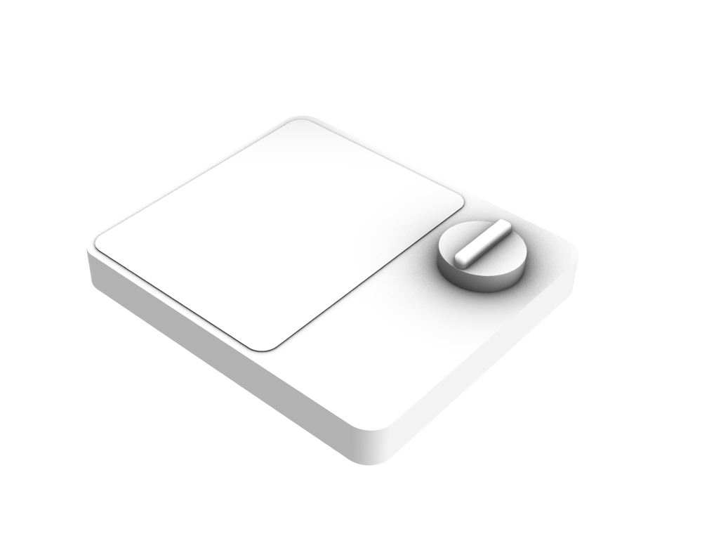
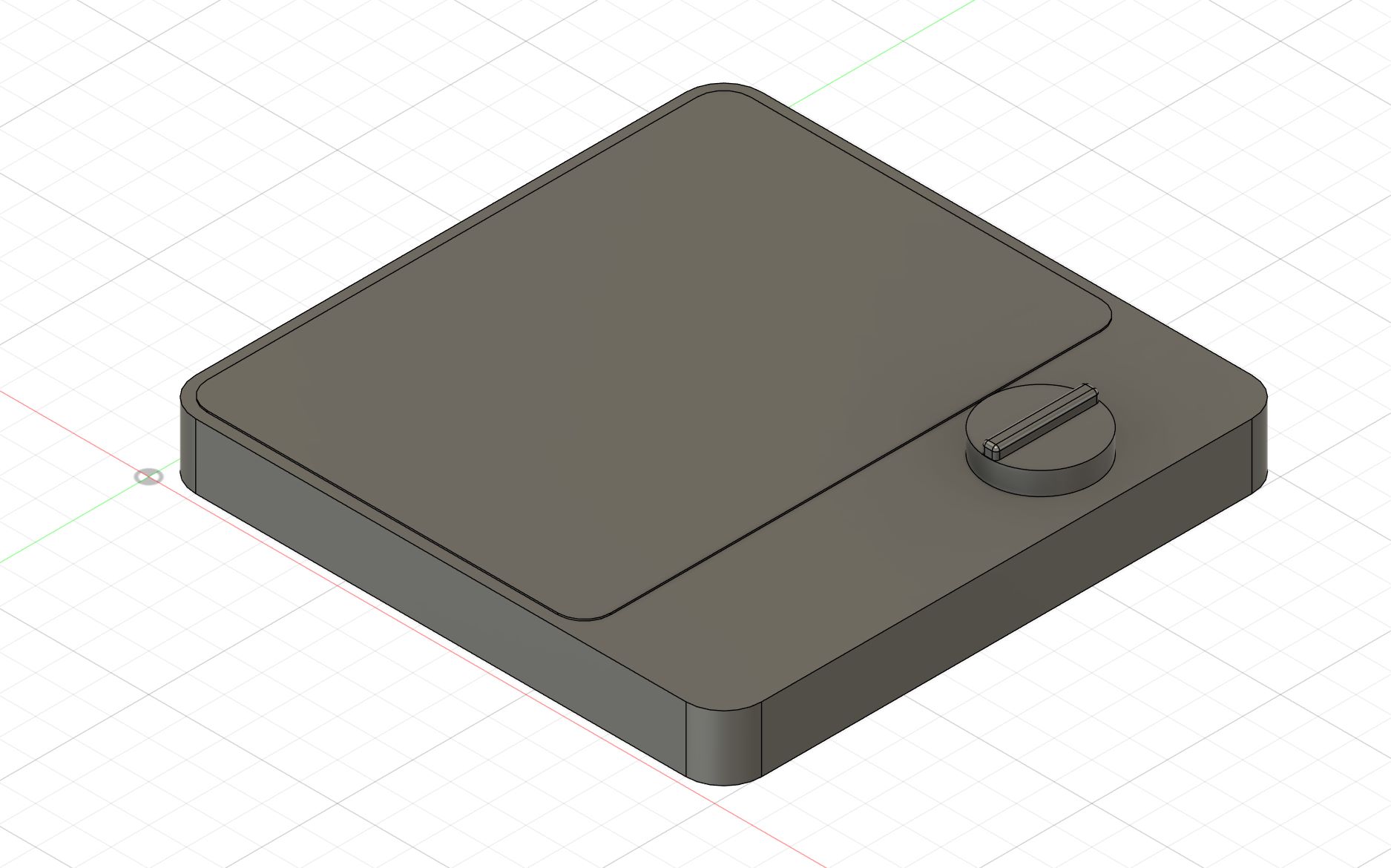
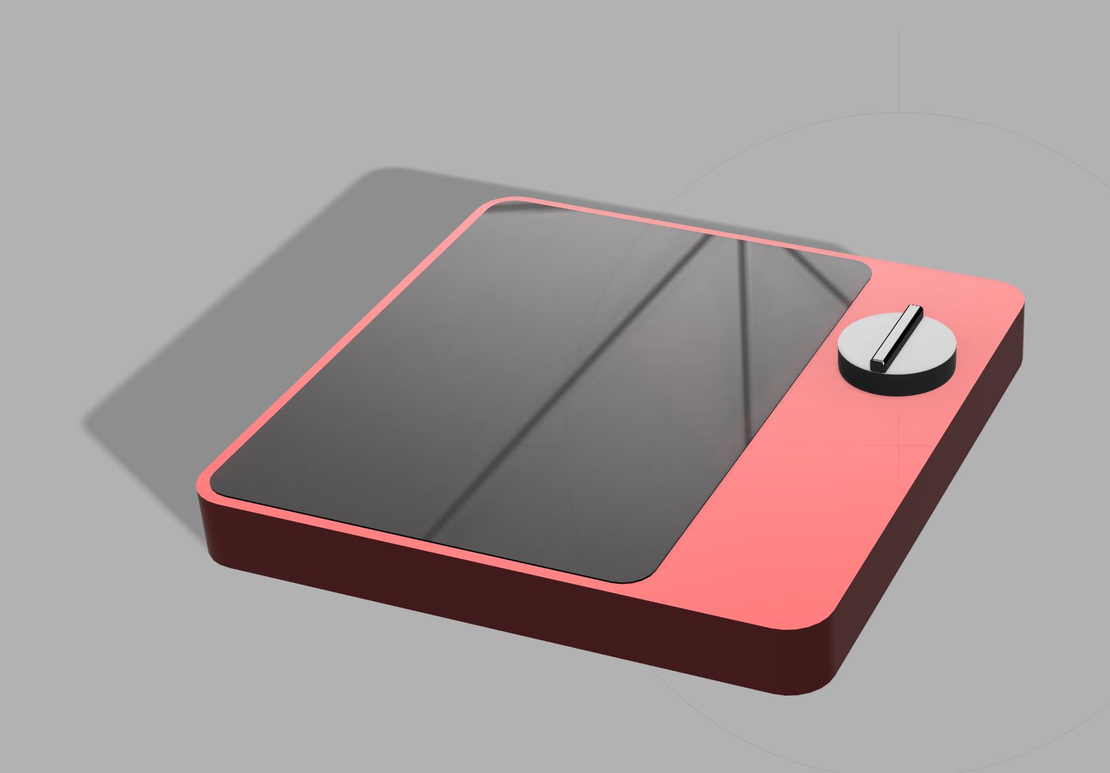
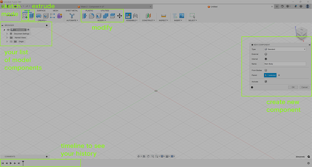 For this walkthrough, I am going to model the 4th Component, the Wireless Display. Which includes modeling 3 items - a main base body, a screen, a knob
Modeling the Main Body
- Enter
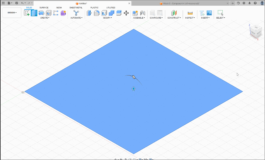
Sketch Modeand and chose the xy plane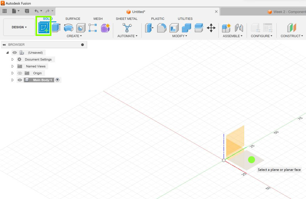
- Draw a square. Use the
dimensionto set the right length. More on dimension later.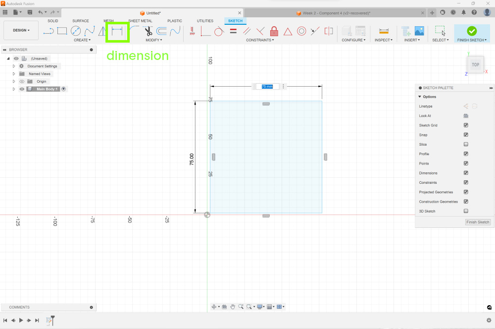
- Once you are satisfied, we can exit sketch mode by pressing
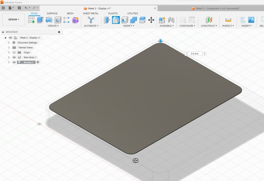
Finish Sketch. - Time to extrude! Set your preferred height. For this model, I set the height to 8.6mm
- Next I
filletthe 4 edges to make rounded corners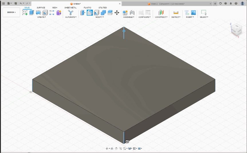
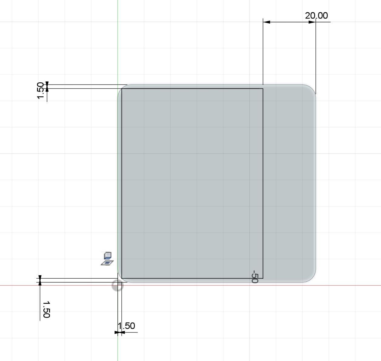
Modeling the Screen
- Start with
new componentand follow the similar steps above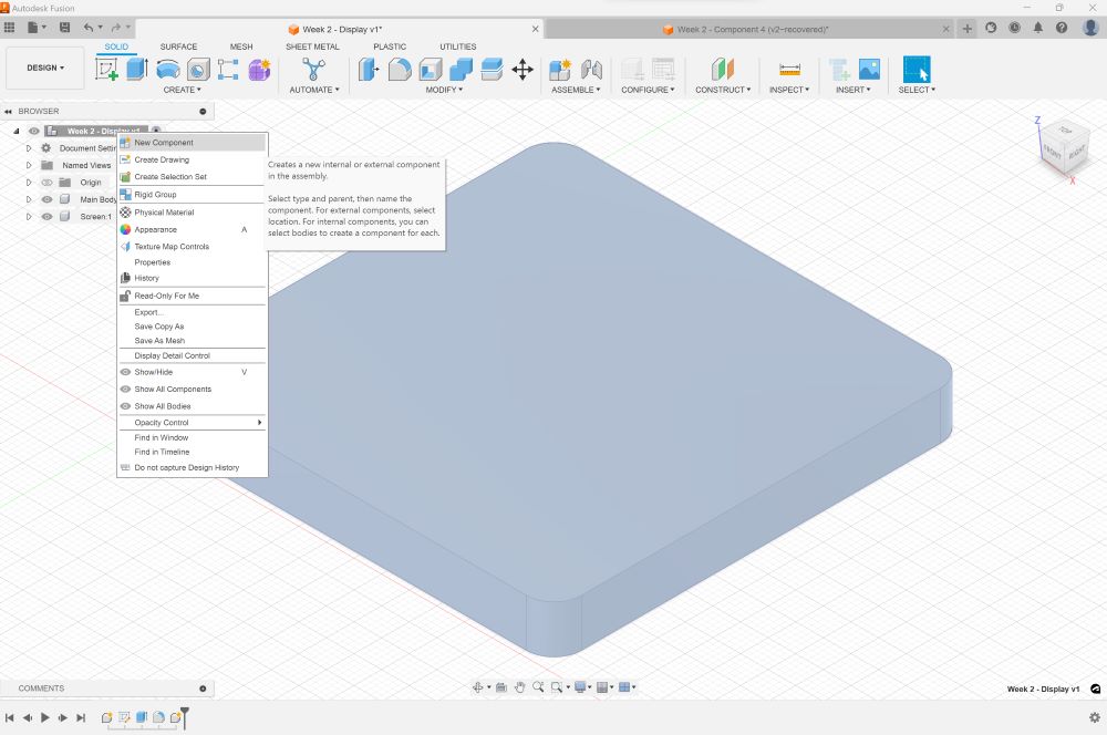
- This is what I found interesting about the
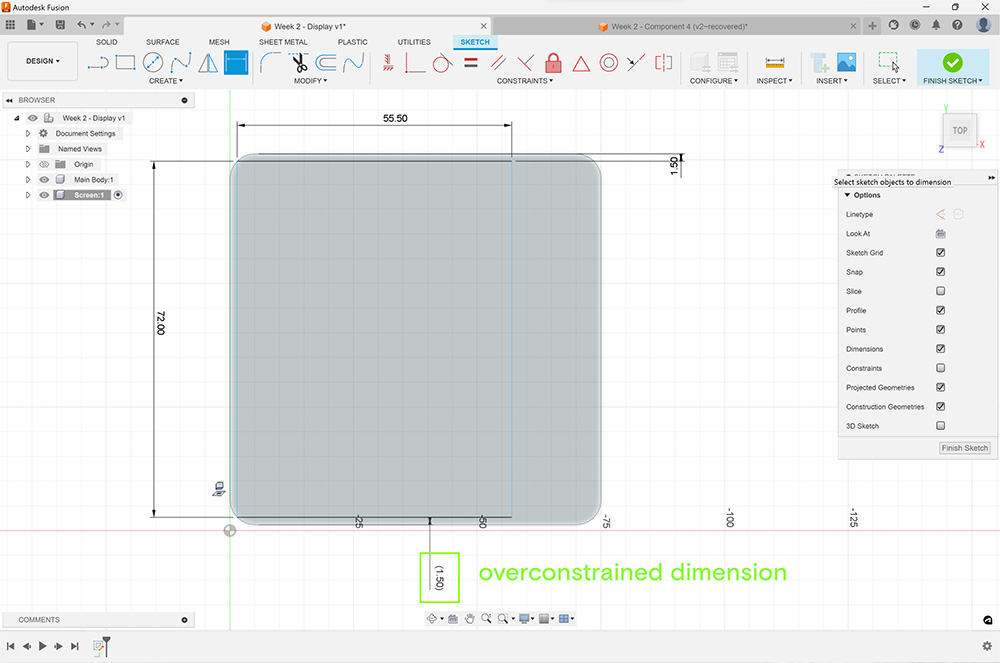
dimensionbutton. In Rhino, dimension is meant to annotate the distance between two points. So I was running Fusion’s dimension button the same way as I normally do in Rhino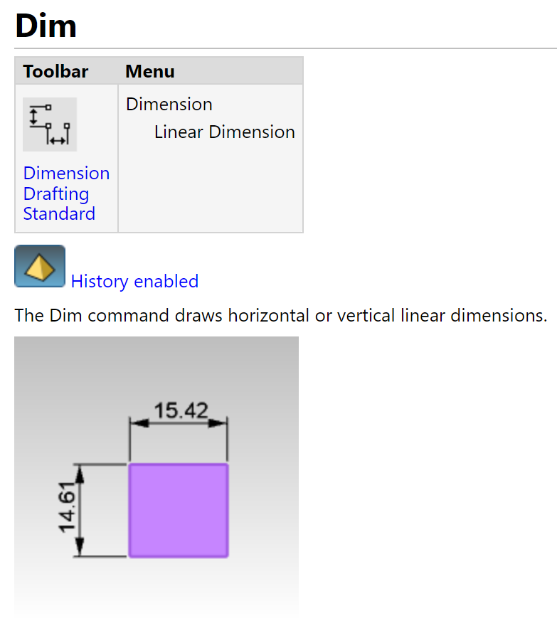
- As I was annotating the measurements, I got an error notice about “overconstraining”. I learned from Eka, that apparently dimension in Fusion works more as a shape getting constrained to a certain parameter rather than for annotation purposes. So if I were to use dimension, it is to set my parameters accordingly. The idea is if we are to let’s say modify the whole model - like resizing, everything will still stick to the same parameter and is accurate in size and points.
- New Parameter Fix
- Extrude & Fillet
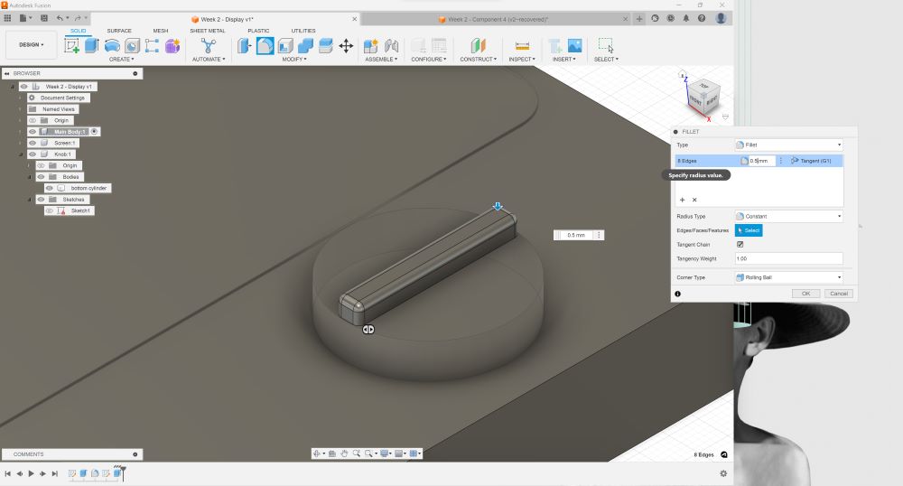
Modeling the Knob
Putting it all Together
Modeling in Rhino 3D
I quickly modeled in Rhino to complete this week’s assignment requirement of exploring different 3D softwares. Keep in note that although the model looks similar… the sizes differ as I wasn’t keeping track of the measurements while quickly building it Rhino. In this section I want to show the difference of modeling in Rhino vs Fusion.
User Interface
This is the user interface of Rhino
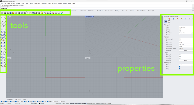 But let me be honest with you..... I never use those functions at all.... I only know about half of these icons.... So wait where do you press or run your tools?
Sketch
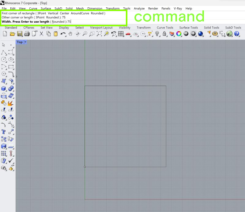 Yes… all I do is just type in Command.... so if I want rectangle, I type
 Rectangle and follow the prompt (which is to insert the point, length and width next). What you need to understand in Rhino is that when you make shape - a lined shape is considered a curve and if your curve has a solid face, we call it surface. This is important to distinguish so you can run the very wide array of commands in Rhino.
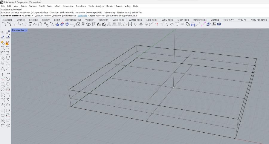
Extrusion
Because our shape is still in the shape of a line - we have to choose type ExtrudeCrv. We want to make a solid model of it instead of just a wireframe so make sure that you opt for Solid=Yes. Type down the length of extrusion you want it to be, which in this case is 8.6mm
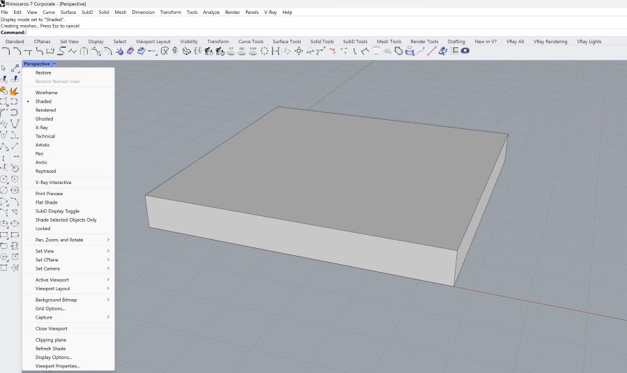
Shaded View
You can check if your model is already Solid from the different preset view provided by Rhino. In this case, Shaded View should suffice.
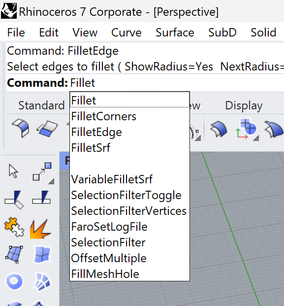
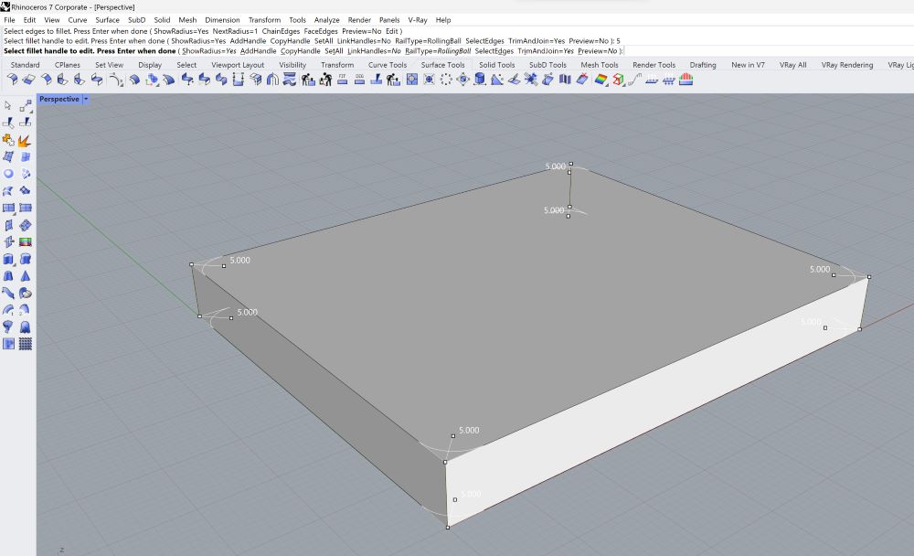
Fillet
As you can see.... there is so many Fillet option… for the component that I want to build, the command FilletEdges would do.
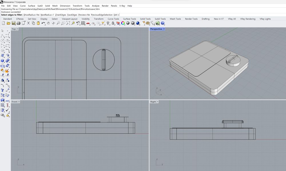
Viewport
I am pretty sure you can also do this 4 Viewports in Rhino but the more components you’re working with, the more useful these viewports will help you
Rendering
Fusion 360
Applying Materials
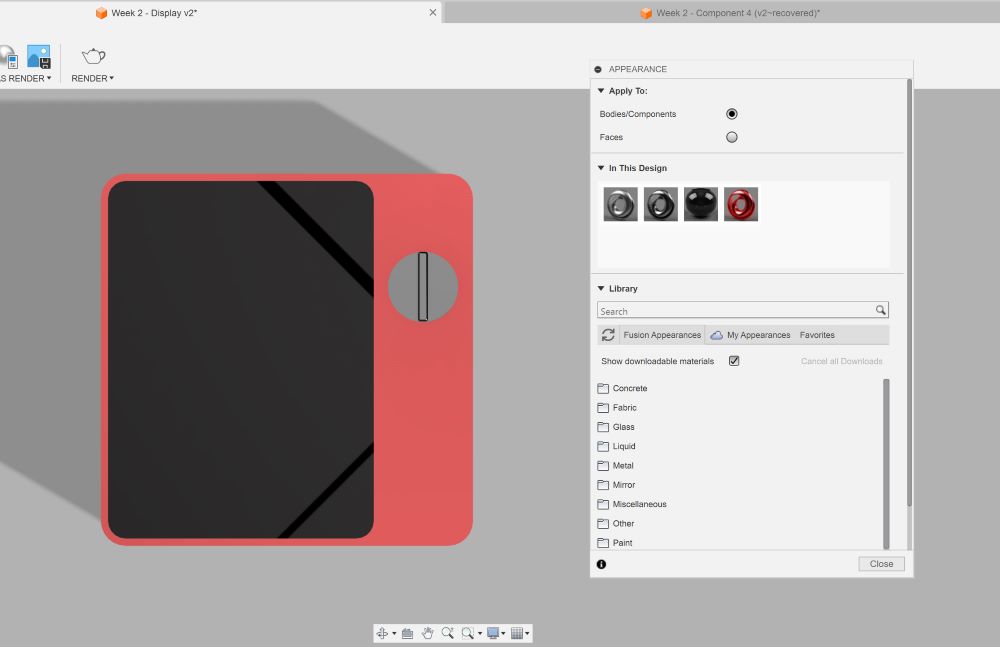
Setting Environment
Hero Shot
Rhino 3D
Rendered with no Material