Task 2: Elaine’s Quentorres Board
This week’s individual task for electronic production week is to replicate the Quentorres Board with Fab Lab Bali’s in-house production process.
You can read more about the Quentorres board from here
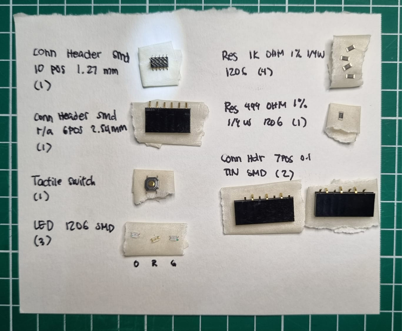
The component needed are as follows:
| Components | Amount |
|---|---|
| SEEED STUDIO XIAO RP2040 | 1 |
| CONN HEADER SMD 10POS 1.27MM | 1 |
| CONN HEADER SMD R/A 6POS 2.54MM | 1 |
| Tactile Switch SPST-NO Top Actuated Surface Mount | 1 |
| LED BLUE CLEAR 1206 SMD | 3 |
| RES 1K OHM 1% 1/4W 1206 | 4 |
| RES 499 OHM 1% 1/4W 1206 | 1 |
| CONN HDR 7POS 0.1 TIN SMD* | 1 |
*: We would recommend not to have the XIAO directly soldered on the board so get that header.
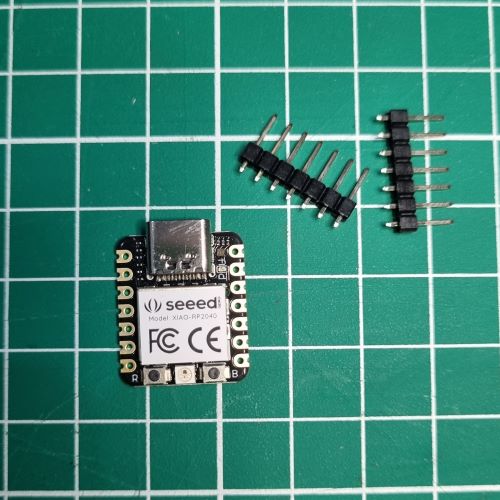
Seeed XIAO RP2040
XIAO RP2040 is a powerful, small, microcontroller unit using the Raspberry RP2040 chip with 264KB of SRAM, and 2MB of onboard Flash memory. This microcontroller has dual-core ARM Cortex M0+ processor, and it can runs at up to 133MHz. Its’ small size makes it suitable for wearable devices and small projects. Our XIAO controllers came unsoldered with the headers, so let’s get to stuffing and programming the board
Stuffing
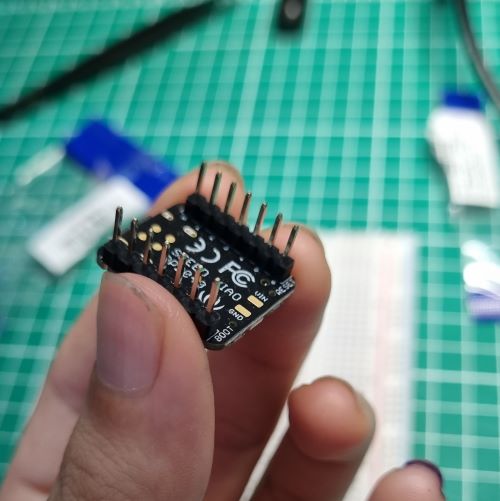
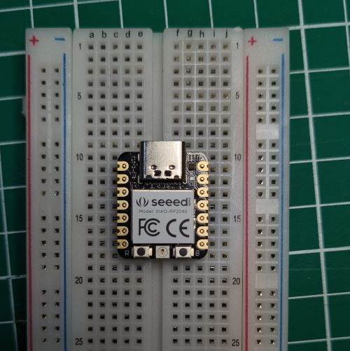
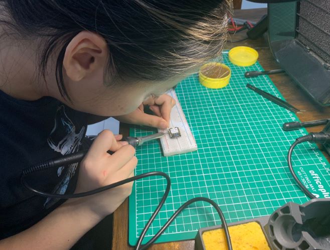
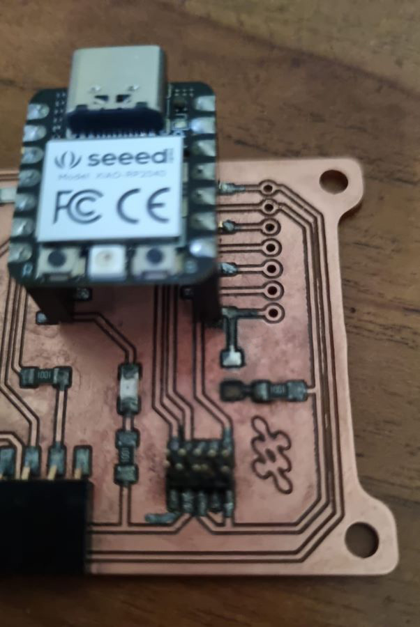
This is the result:
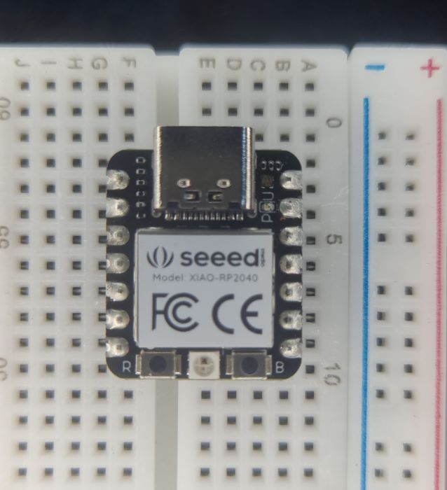
Don’t forget to check for continuity with the multimeter!!!
Programming
Now this is the a Make-it or Break-it moment. To program, open-up Arduino IDE.
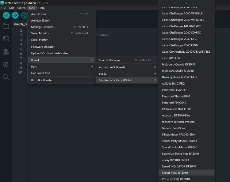
Go to Preferences> Additional Board Management Url, Copy-Paste the following into the entry
https://github.com/earlephilhower/arduino-pico/releases/download/global/package_rp2040_index.json
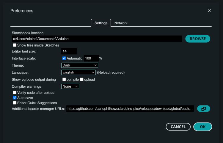
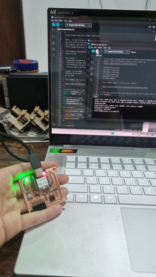
Configure Arduino IDE for the XIAO Board and make sure that the COM recognises the board. If your XIAO board turns on - it’s a good sign.
Run a simple ‘Blink’ Code. Files>Examples>01.Basic>Blink. Change the LED_pin to 25.
/*
  Blink

  Turns an LED on for one second, then off for one second, repeatedly.

  Most Arduinos have an on-board LED you can control. On the UNO, MEGA and ZERO
  it is attached to digital pin 13, on MKR1000 on pin 6. LED_BUILTIN is set to
  the correct LED pin independent of which board is used.
  If you want to know what pin the on-board LED is connected to on your Arduino
  model, check the Technical Specs of your board at:
  https://www.arduino.cc/en/Main/Products

  modified 8 May 2014
  by Scott Fitzgerald
  modified 2 Sep 2016
  by Arturo Guadalupi
  modified 8 Sep 2016
  by Colby Newman

  This example code is in the public domain.

  https://www.arduino.cc/en/Tutorial/BuiltInExamples/Blink
*/

// the setup function runs once when you press reset or power the board
void setup() {
  // initialize digital pin LED_BUILTIN as an output.
  pinMode(25, OUTPUT);
}

// the loop function runs over and over again forever
void loop() {
  digitalWrite(25, HIGH);  // turn the LED on (HIGH is the voltage level)
  delay(1000);                      // wait for a second
  digitalWrite(25, LOW);   // turn the LED off by making the voltage LOW
  delay(1000);                      // wait for a second
}
If your XIAO board is blinking that means congrats! It’s a good start.
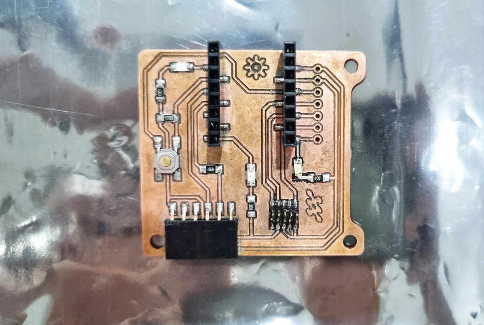
Quentorres Board
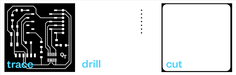
You can get the png file for The Quentorres Board from here The workflow requires 3 processes.
- Tracing the Circuits
- Drilling Into the Hole
- Cutting the Interior from the FR1 Copper Board
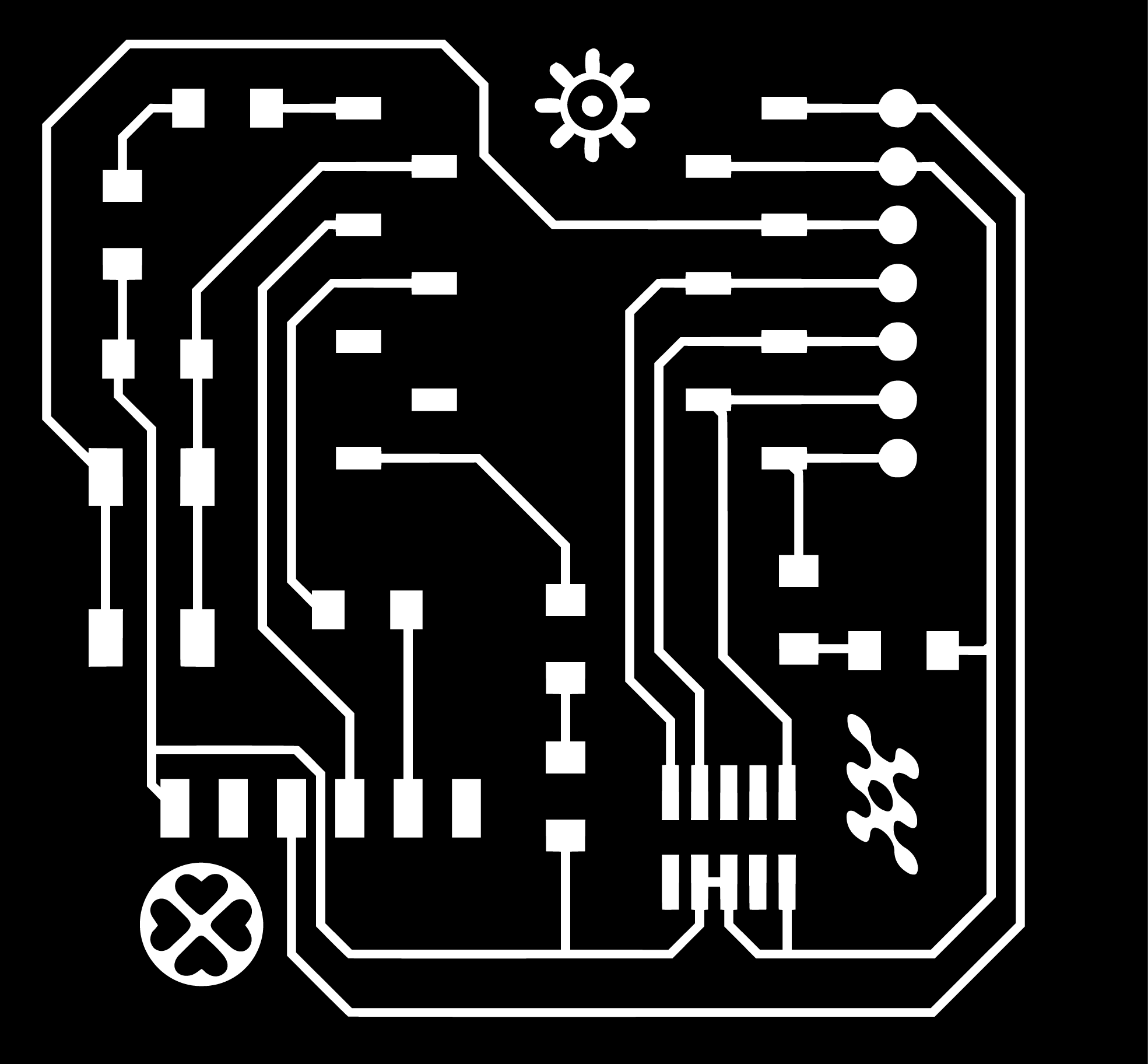
Customising
I went for simple customisation on the tracing process by adding several cute y2k-inspired icons using vector-based software. Just make sure that when you export the document, the file follows the original resolution (1000dpi) and the original height is at 1824px.
MODS
Open MODS. Right Click > Programs > Open Program > Find gcode Mill 2D PCB
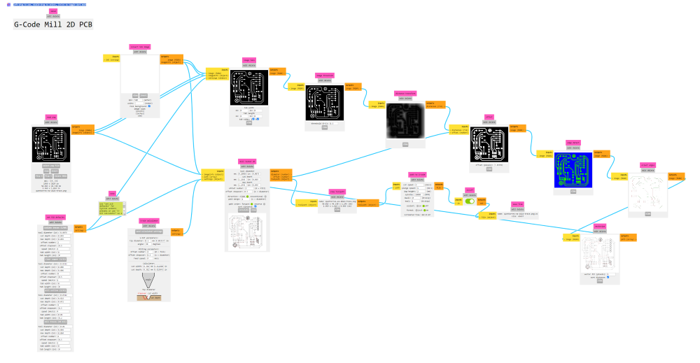
Tracing Settings -VBit
-
Insert the Tracing .png file in
read png.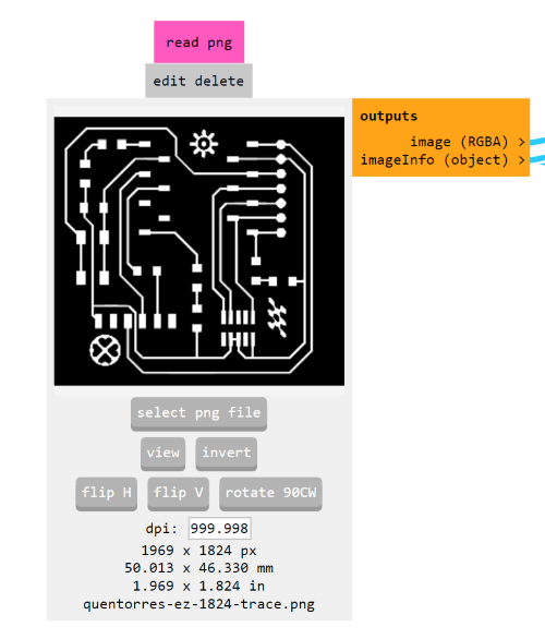
-
Go to
set PCB defaults. Because our 1/64 endmill wasn’t cutting as well as we hoped for, we decided to use the VBit. The VBit settings that we configured based on the trial and error process we did in the group assignment are as follows.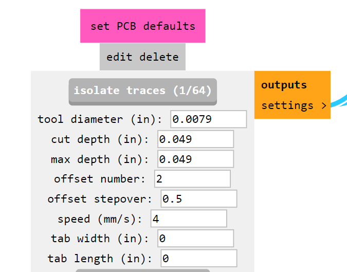
-
Press
isolate tracesand head toPath to G-Code, insert the following setting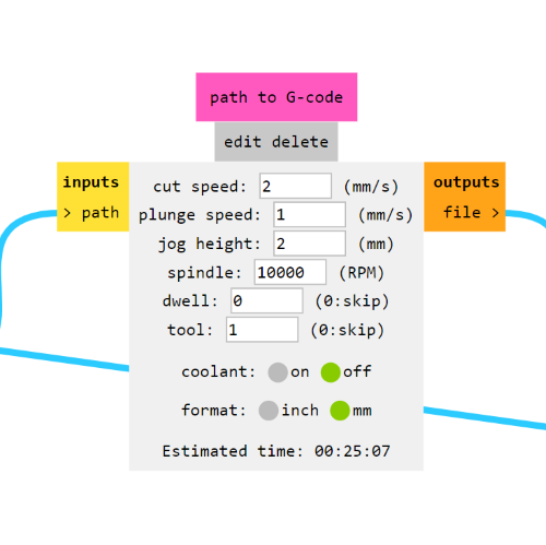
-
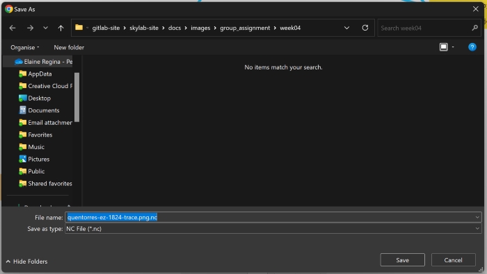
Head to
mill raster 2d, check if your settings are already right and presscalculate. A save window should pop up with a g-code file that has been generated with a.nc.file type.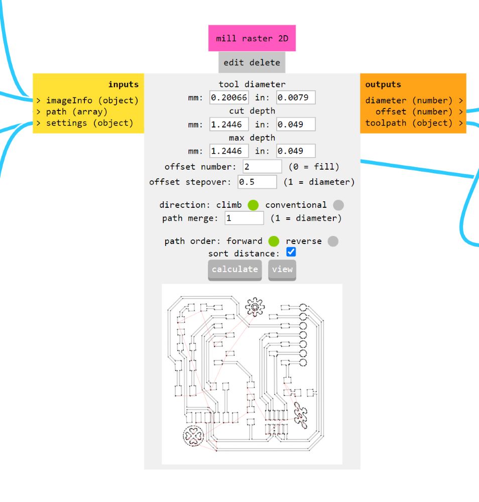
-
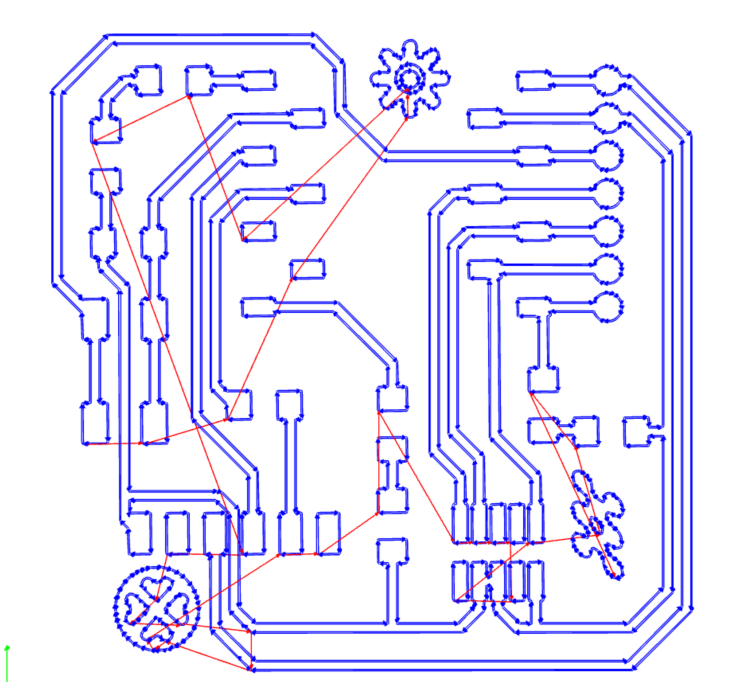
Head to
view toolpathfor a simulated workflow that will be run by the machine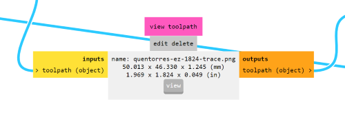
Drilling & Cutting Settings
-
Insert the Drilling and Cutting .png files in
read png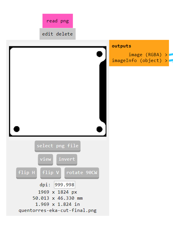
-
We will be using the 1/32” Endmill for cutting and drilling. In
set PCB defaultsfollow these settings
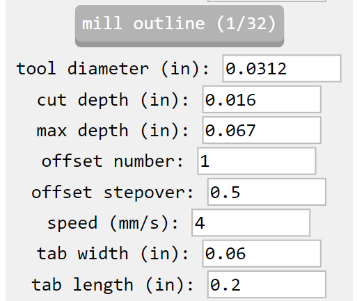
-
Press the
mill outlines, go topath to gcodefollow these settings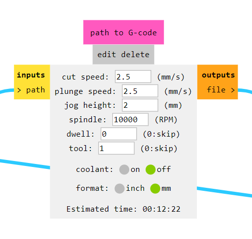
-
mill raster 2d>calculate>save .nc file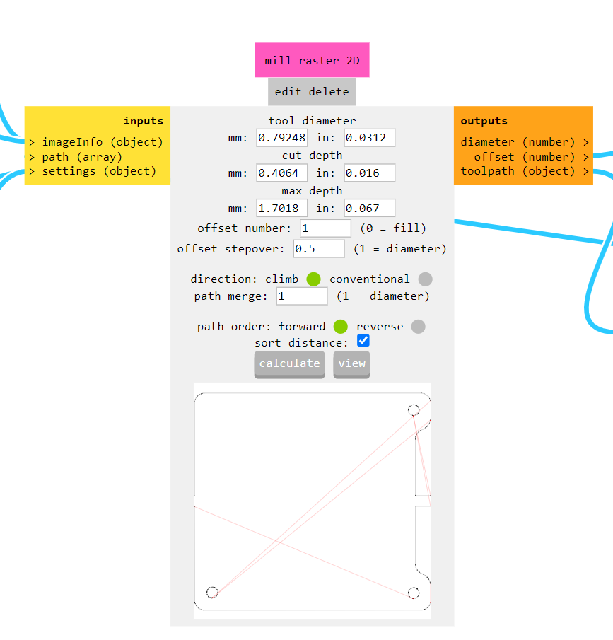
-
view toolpath>viewto make sure the toolpath suits right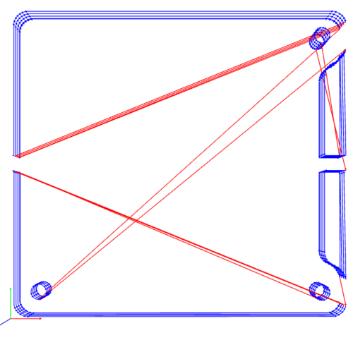
Milling
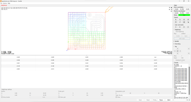
This week I worked on Candle software to operate the GRBL firmware that comes with the Sainsmart Genmitsu 3018-PRO CNC Router DIY Kit. Order of PCB production after setting up the gcode files to be operated is to > Set XY (0,0) for Home > Z-probe > HeightMap > Airpass > Mill.
1st Board: Failure
The VBit has undergone 3 Tracing Jobs before mine and the result is that the circuit lines were too thin with some getting completely rubbed off.... Using the multimeter some doesn’t have continuity, so it’s a failure.
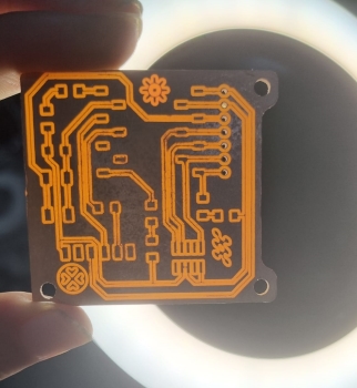
2nd Board: Getting There
I changed into a new V-Bit and the result of the tracing is cleaner. I was using the leftover FR board drom the previous job. While airpassing, because the cutting job would be very close to the edges which seemed very risky, I just decided to do trace+drill. The jig wasnt really holding well the smaller board either (maybe I placed it loosely or wrong) so the small circles were drilled out of place…
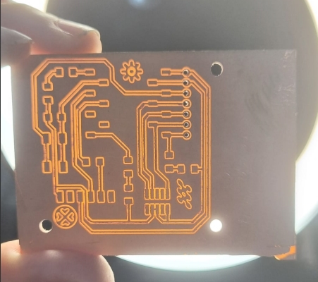
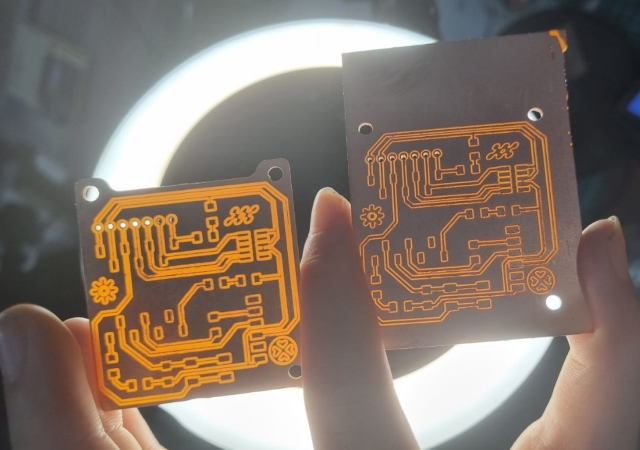
However, as I did a continuity test with the multimeter, I found that everything was working just fine. So I have a Quentorres with a very huge Ground plane.
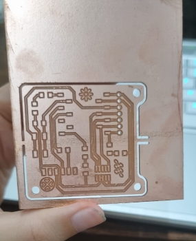
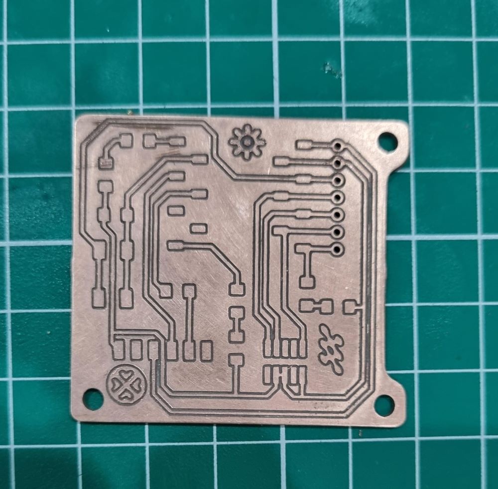
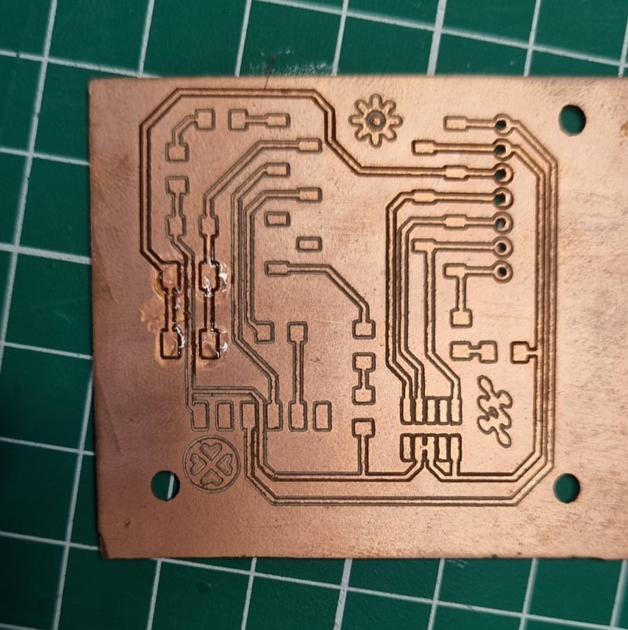
3rd Board: Success!!
I managed to mill a third board successfully. Sand the board with a fine grit sanding paper to smoothen out the surface. I want to share some personal findings after going through multiple trials and tribulations with milling the Quentorres board.
Milling with Genmitsu 3018 Tips that may be helpful
-
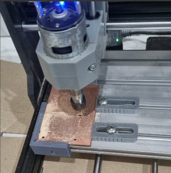
A good distance from the spindle to the milling bits would ideally be (15mm). Beyond 15mm the trace would be too deep; less than 15mm, the mill will not cut through
-
Airpass. Airpass is very important, it would reduce the chance of failure
- Heightmap. I learn that a PCB board is not always flat. Heightmap will help to make the machine adjust to the PCB - especially if you’re using a jig rather than a sacrificial board
- The more you mill, the more you cause wear and stress on the milling bit. This can affect your milling results. In the context of tracing, after several mill jobs - you can start offsetting the height so that your trace tracks will come out cleanly.
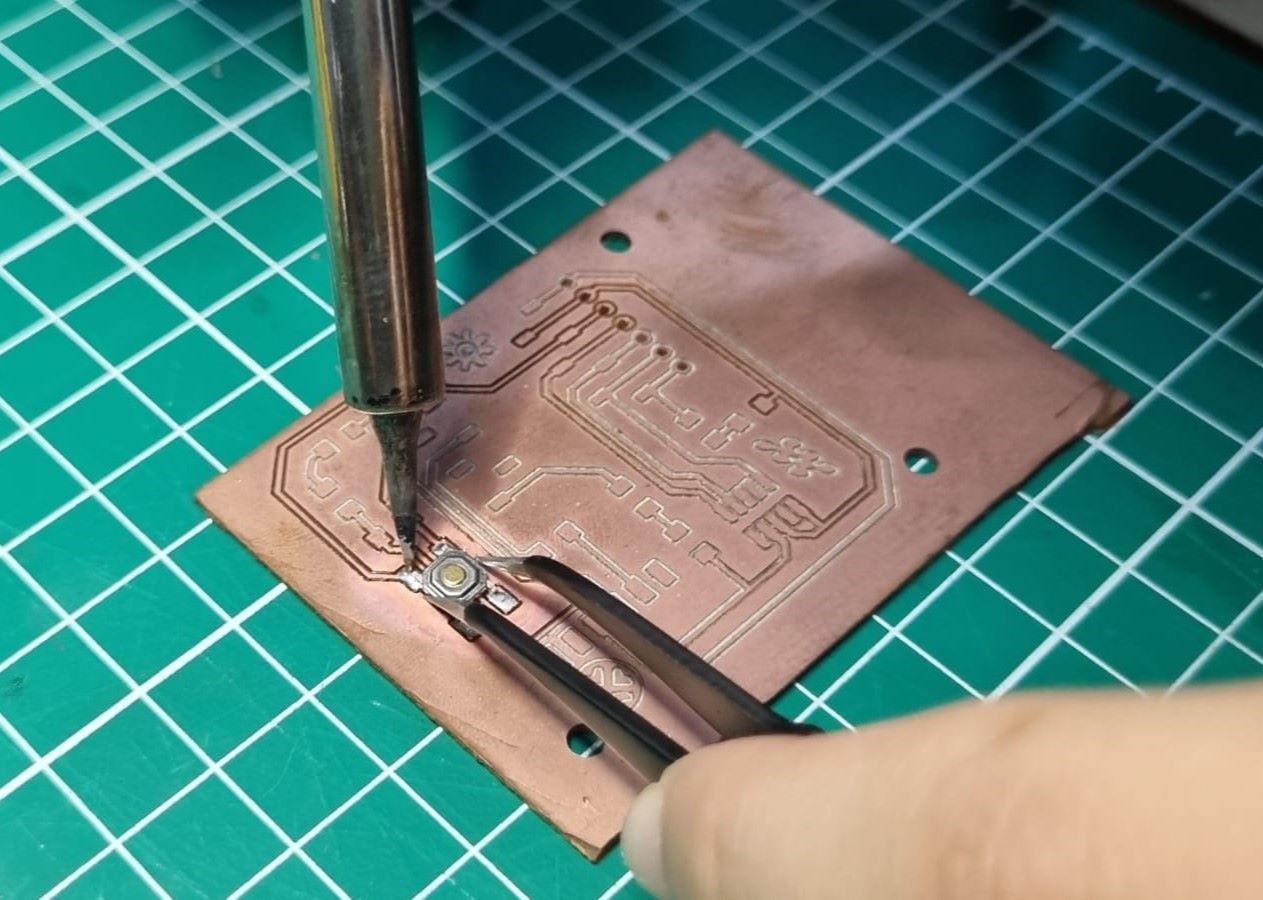
Stuffing
I have never stuffed directly on a copper board with massive ground plane area… my only experience with stuffing was on a board that has been coated with a UV mask......
Soldering Good Practice
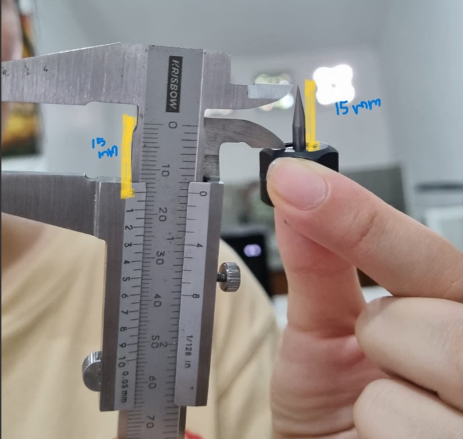
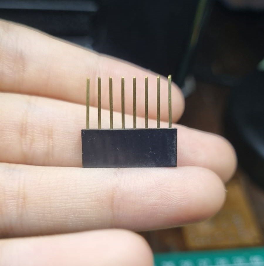
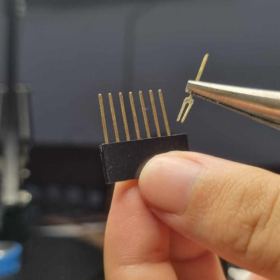
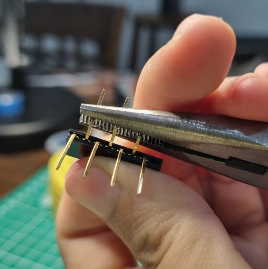
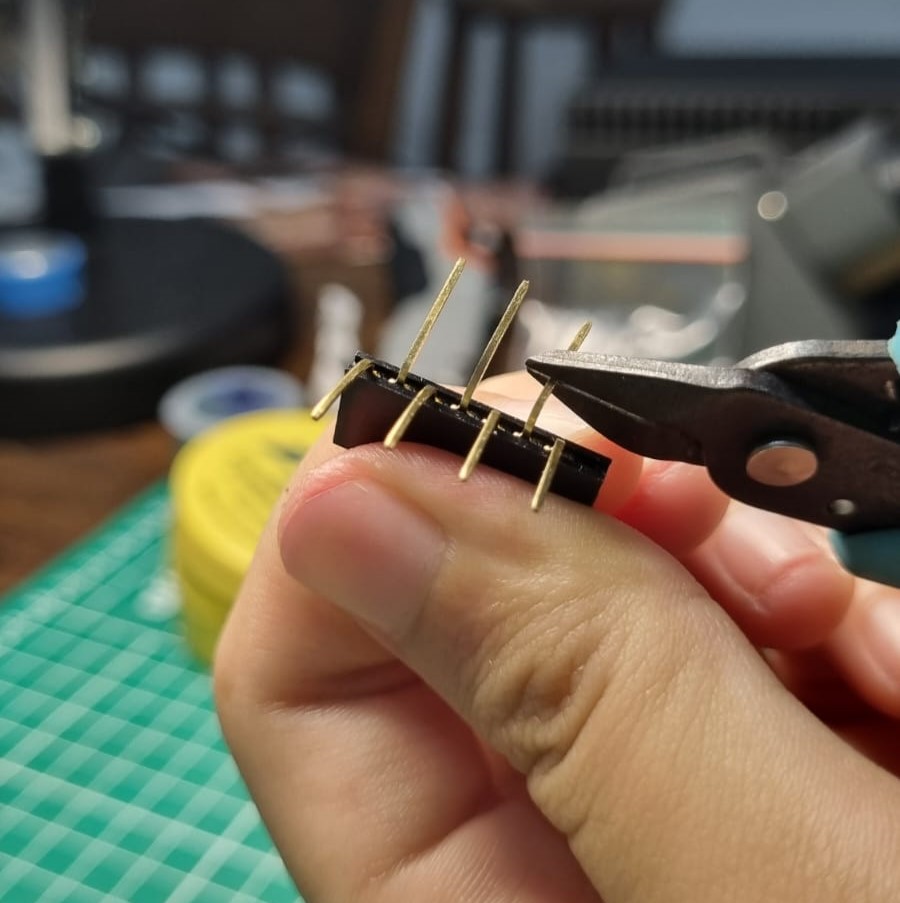
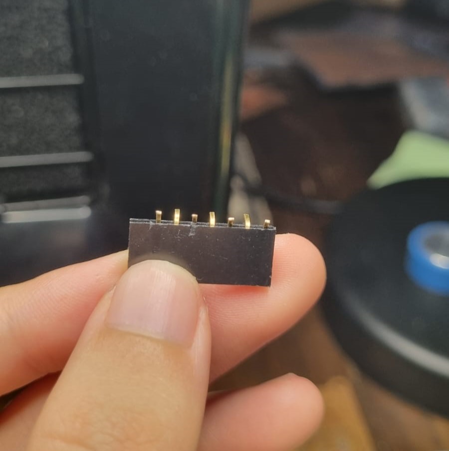
- Prepare your necessary electronic componenets before hand. Write down the components that you need on a paper and attach the following components. A bit of fun tip… we couldn’t get the required 7 pin header in Bali so we hacked the 8 pin socket header!
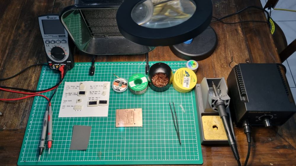
- Make sure that you have your table ready with the required equipments to do stuffing. This includes
- soldering iron
- solder wire
- copper spool
- flux
- tweezers
- fume extractor
- lamp
- soldering wick
- multimeter
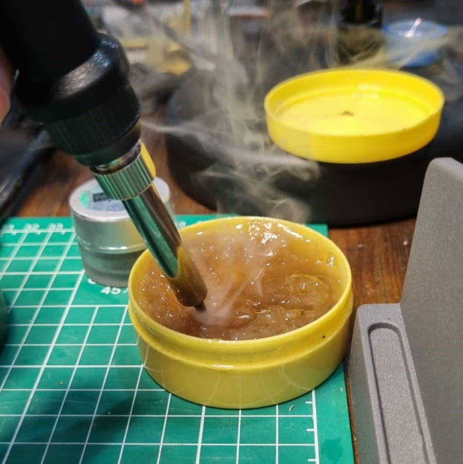
- tip refresher
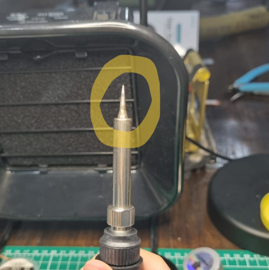
- Your soldering iron tip needs to be shiny and not oxidised. To keep the tip shiny, always tin the tip with solder to avoid oxidation. Brush it with the copper spool in a revolving motion when you’re going to use the solder. You can also use a tip refresher if the soldering iron tip had become too oxidised.
- Always flux - this helps to spread the solder to the copper board evenly.
- Order of work: Flux the board –> flux your tip –> heat the board with the soldering iron –> tin with solder –> spread the solder onto the board –> attach your component by reheating the solder
- The standard temperature level to solder is at 320°-350°C
- If you use too much solder, wipe it with the solder wick. Flux the wick before picking up the excess solder
- The multimeter will be your friend to check if your soldering job is fine or not. Make sure to check as you solder the components so that you can avoid having unwanted continuity or possibility of shorting.
First Board: Horrible
I have no words to say other than it’s a nightmare. In my defence - my tip wasn’t shiny so I had a hard time tinning with the solder and I increased the temperature to 400°C (don’t! you’ll destroy the copper layer - see how I made holes onto the footpad)
Second Board: I did it.... but BIG OOPS!
Hooray I did it!!!!
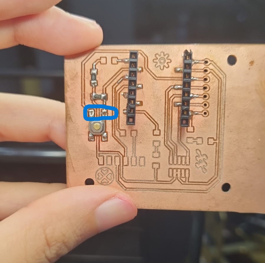
However.... I didn’t take a hero shot upon immediate success. I thought I’ll wait till the morning to get some natural lighting but upon closer inspection.... the LED wasn’t soldered right in place which caused unwanted shorting the next morning when I finally mustered up the motivation to document my work.
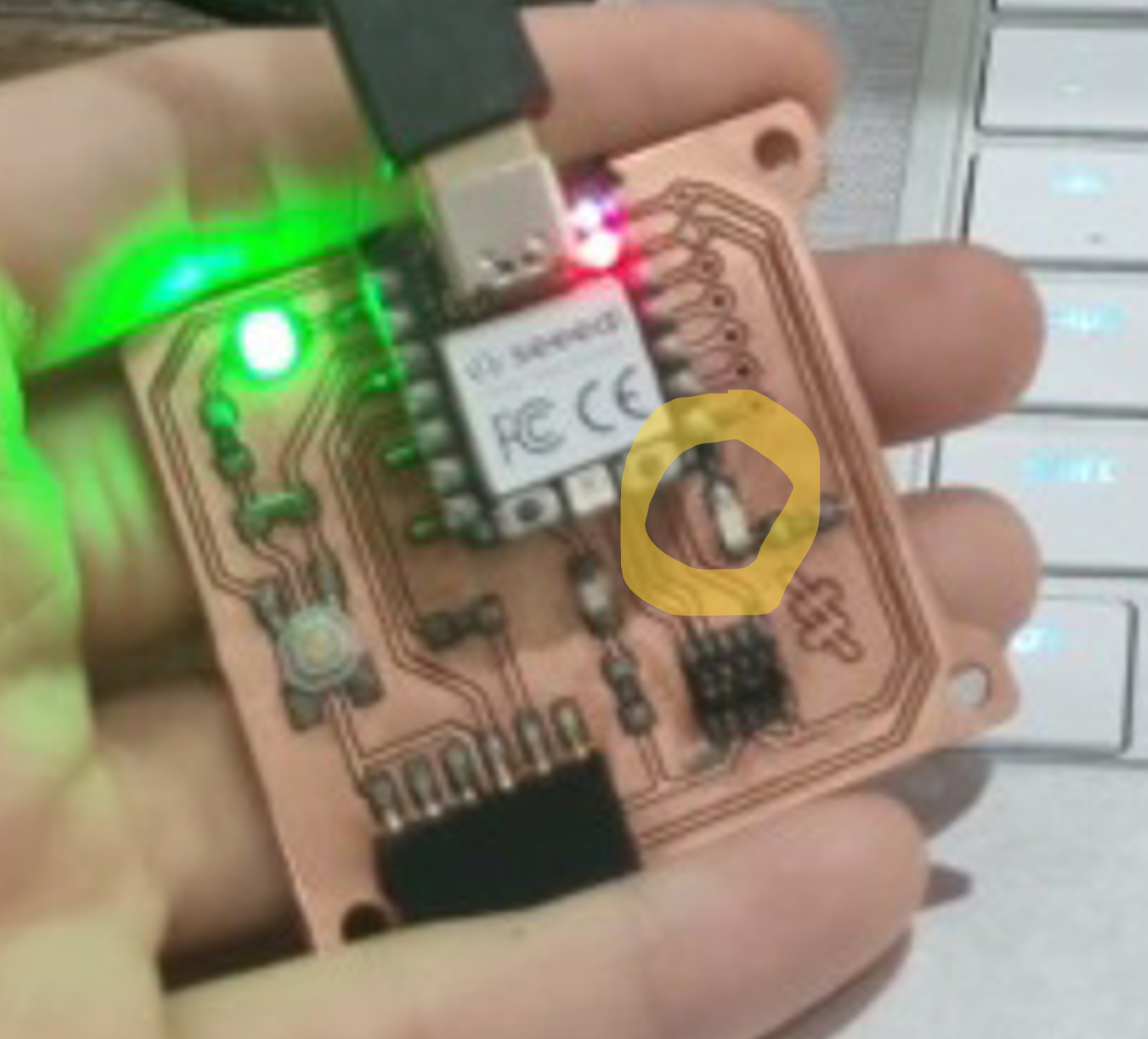
So I tried to fix it but.....

Can’t be bothered milling another board… let’s repair it!!!
We didnt have a jumper wire and I was too lazy to mill another board just because of a missing footpad..... so I decide to do some big brain move with all my trials and tribulations and fix the board.
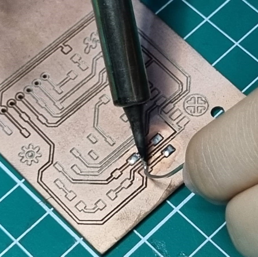
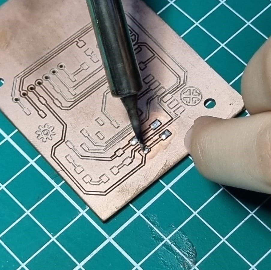
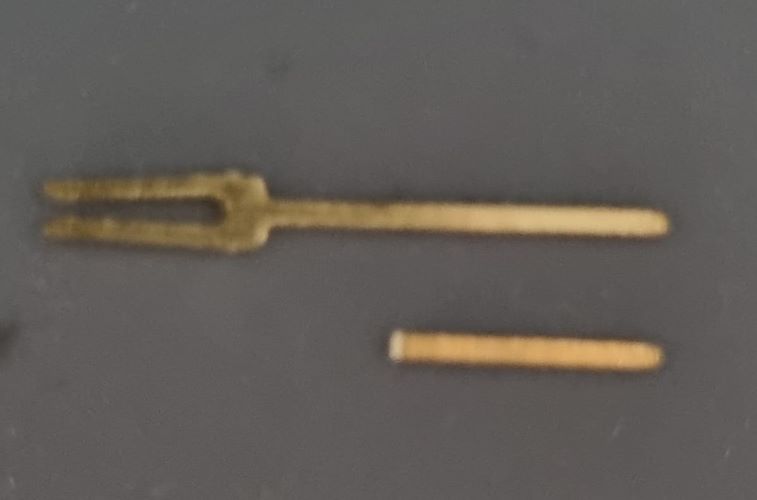
Modern problem requires modern solution. So I took the extra pin from the customised pin headers and cut it equal to the length of path from the resistor to the LED (a jumper pin!)
Next I solder the jumper pin from the end of the resistor footpad to the end of the LED footpad. Since the jumper pin is flat - if i dont solder it at a certain angle , positioning it flat will cause some shoring as the pin will be directly touching the ground plane. However.... remember that I caused some holes in my first soldering try?? I decided to just make a border around the jumper pin… yes, I made a path through force with the soldering iron (when there is a will, there is a way!)
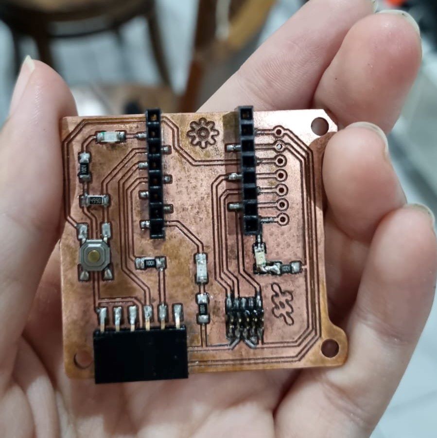 Excuse my oxidised board… Bali is very humid and we live very close to the beach. The solder is looking shinier because I refluxed it with a new flux (please don’t use a 10 year old flux - I learned my lesson)
Programming
/*
  Blink

  Turns an LED on for one second, then off for one second, repeatedly.

  Most Arduinos have an on-board LED you can control. On the UNO, MEGA and ZERO
  it is attached to digital pin 13, on MKR1000 on pin 6. LED_BUILTIN is set to
  the correct LED pin independent of which board is used.
  If you want to know what pin the on-board LED is connected to on your Arduino
  model, check the Technical Specs of your board at:
  https://www.arduino.cc/en/Main/Products

  modified 8 May 2014
  by Scott Fitzgerald
  modified 2 Sep 2016
  by Arturo Guadalupi
  modified 8 Sep 2016
  by Colby Newman

  This example code is in the public domain.

  https://www.arduino.cc/en/Tutorial/BuiltInExamples/Blink
*/

// the setup function runs once when you press reset or power the board
void setup() {
  // initialize digital pin LED_BUILTIN as an output.
  pinMode(26, OUTPUT);
}

// the loop function runs over and over again forever
void loop() {
  digitalWrite(26, HIGH);  // turn the LED on (HIGH is the voltage level)
  delay(1000);                      // wait for a second
  digitalWrite(26, LOW);   // turn the LED off by making the voltage LOW
  delay(1000);                      // wait for a second
}