PROJECT DEVELOPMENT
Welcome to my page where I show all the development of my final project. It has been a path with many setbacks and difficult weeks, but the idea is to enjoy each process. Here I leave everything developed and I hope you like it.
- What tasks have been completed, and what tasks remain?
- What's working? what's not?
- What questions need to be resolved?
- what will happen when?
- what have you learned?
I invite you to review the entire process of my project where you can discover the difficulties and achievements made in each step. I did my documentation in spirals for each process developed so that they can understand a way to achieve the final project. The methodology was to work in parallel and in spirals, where each process evolved and integrated with others to achieve the objective. Here you can review my entire process.
PRINCIPLES AND PRACTICES
SKETCH
The following task was carried out in week 1, here is the link. PRINCIPLES AND PRACTICES
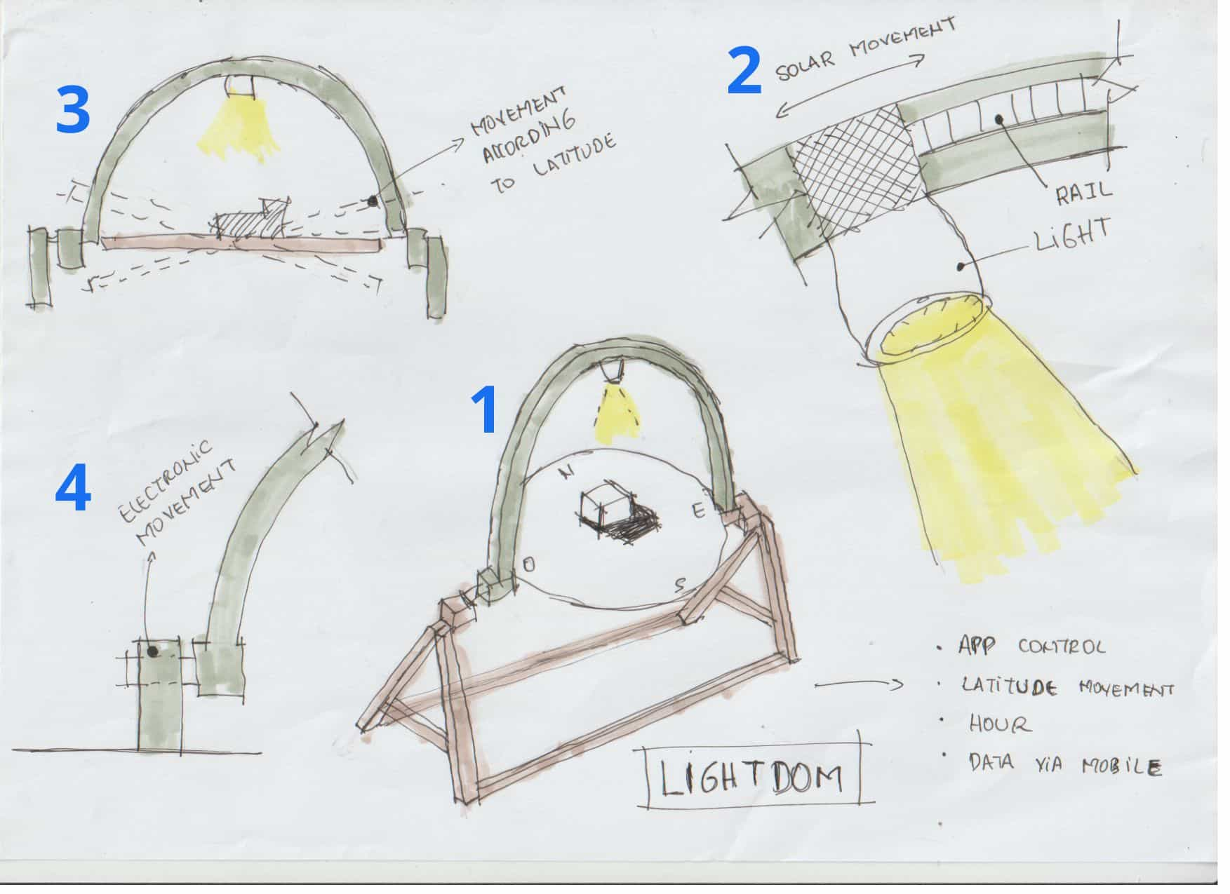
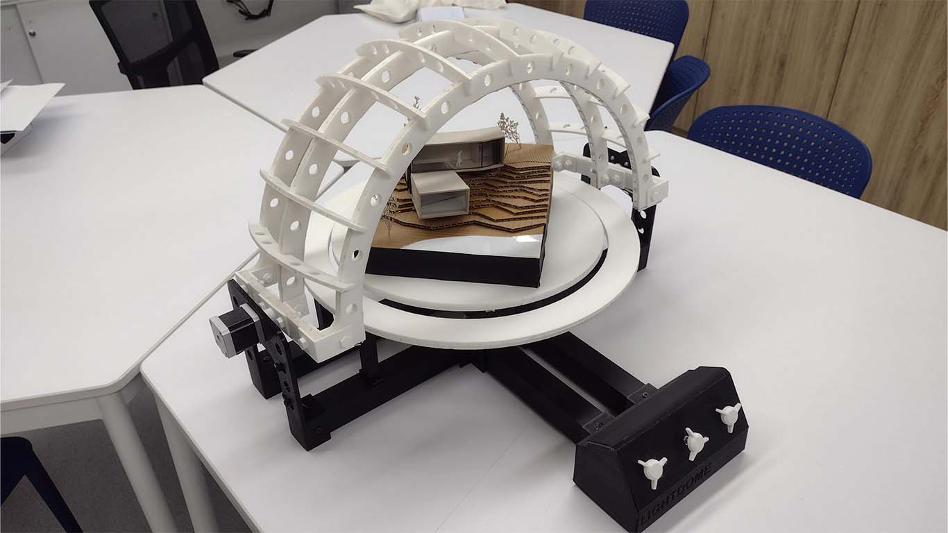
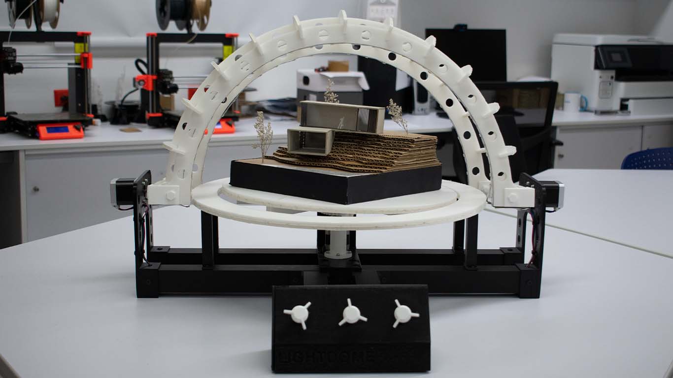
In the first week I wanted to develop LIGHTDOM, an artifact that simulates the movement and incidence of the sun in architectural projects. It is inspired by HELIODON, which is an instrument that architects use to study the movement of the sun throughout the year and see the impact it has on our projects when designing to take advantage of it or avoid it. The objective of the project is to create the artifact for the education of young architects who are starting their careers and who can understand the importance of solar analysis in architecture. Nowadays, many of them are complicated and the analysis is not clear when it comes to explanation since it is difficult to understand only with diagrams and graphs. Therefore, to understand and make them understand better, my goal is to develop this artifact to apply to their architectural projects and designs so they can understand the importance.
PROJECT MANAGEMENT
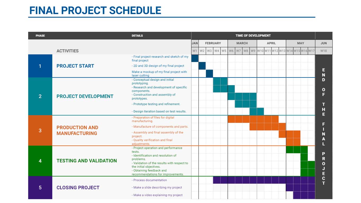
On the other hand, I also proposed my project management to achieve the development of my final project. Here I was able to divide it into every week and be able to work on a little bit of my final project every week. It has been difficult to consolidate my project management over time, sometimes I couldn't give much time to my final project and I tried to organize myself better. Remember that we have to work in SPIRAL and PARALLEL to achieve both the weekly assignments and achieve the final project. Here is a screenshot of my PROJECT MANAGEMENT to achieve the objective.
COMPUTER AIDED DESIGN
DESIGN 2D AND 3D
The 2D and 3D design of my final project began in week 2, here is the link if you want to know more about the evolution DESIGN 2D AND 3D
For week two we had to develop and model our possible final project in 2D and 3D programs. In my case, I developed a LIGHTDOM proposal, here are some screenshots that I was able to develop as an assignment for this week.

DESIGN 2D
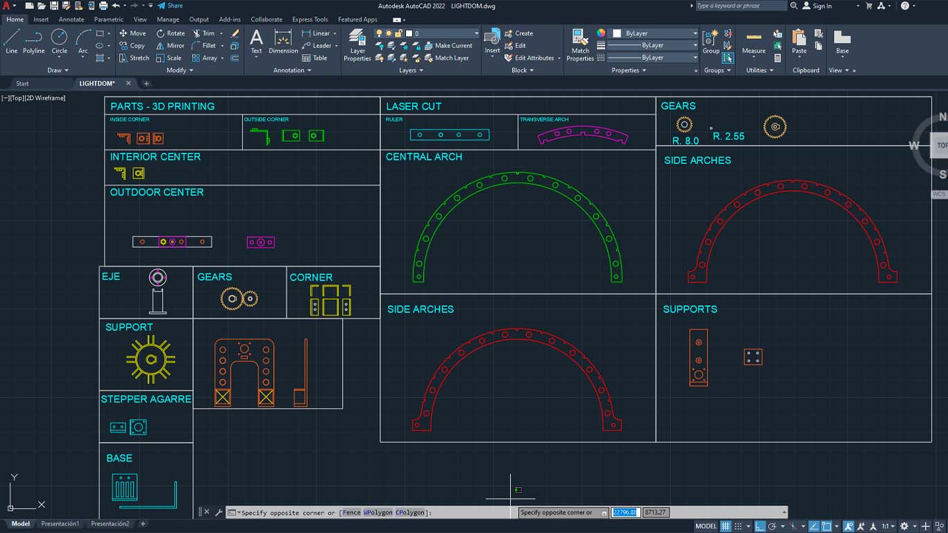
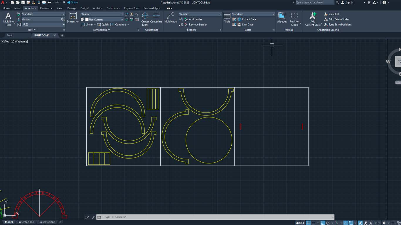
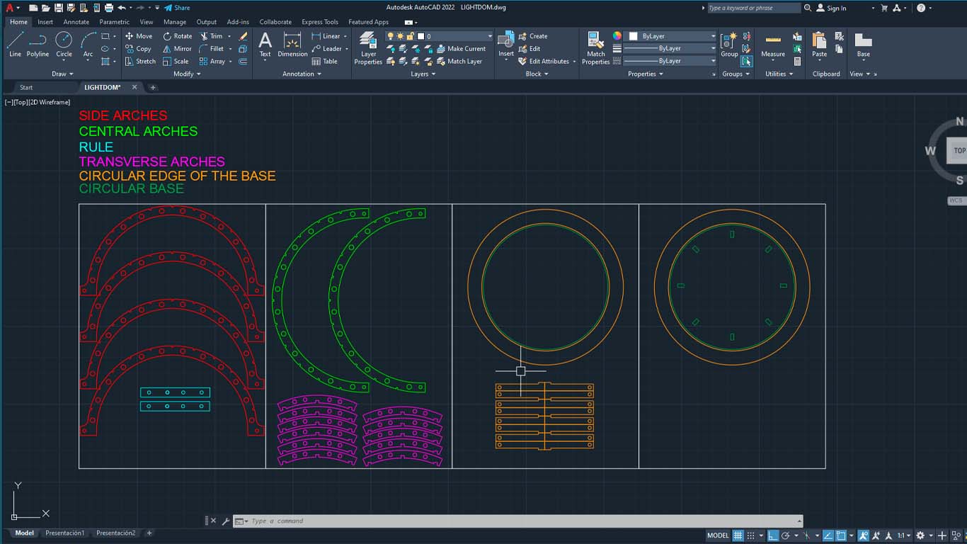
For the 2D design of my project I used the AUTOCAD program, since it is a program that I use easily due to the degree I studied. In the program I designed my entire project and then exported them to FUSION to work in 3D. Here is a screenshot of my file where day by day I made changes according to the result I was obtaining.
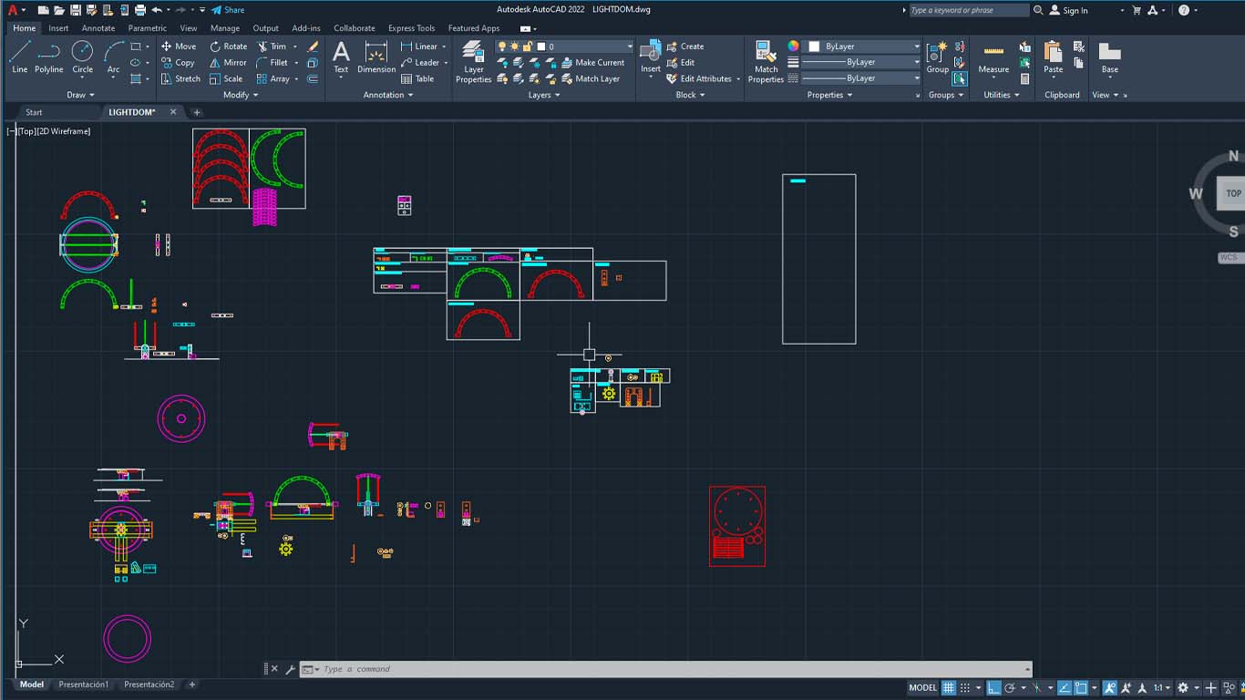
Finally, I put each part of my final project together in small boxes to have an order while also doing spiral work to obtain the appropriate measurements for each one. In the following screenshot we can see the parts of my entire project that you can get in the FILES section if you want to replicate or improve my project.
DESIGN 3D
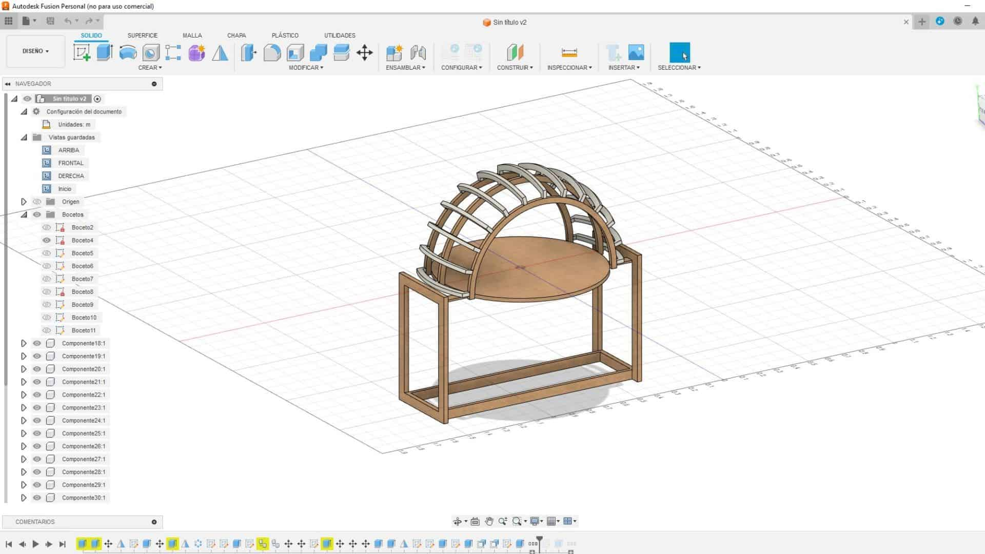
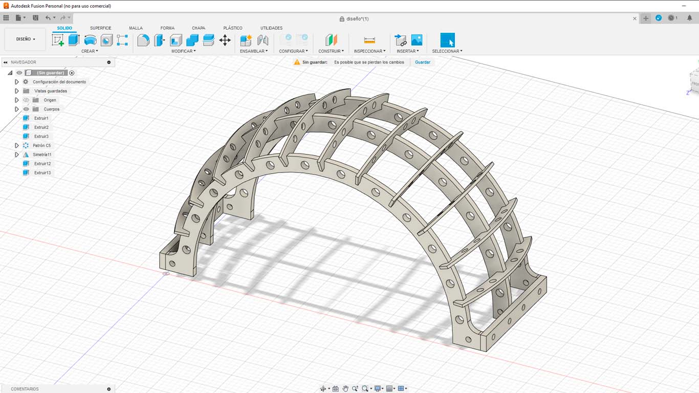
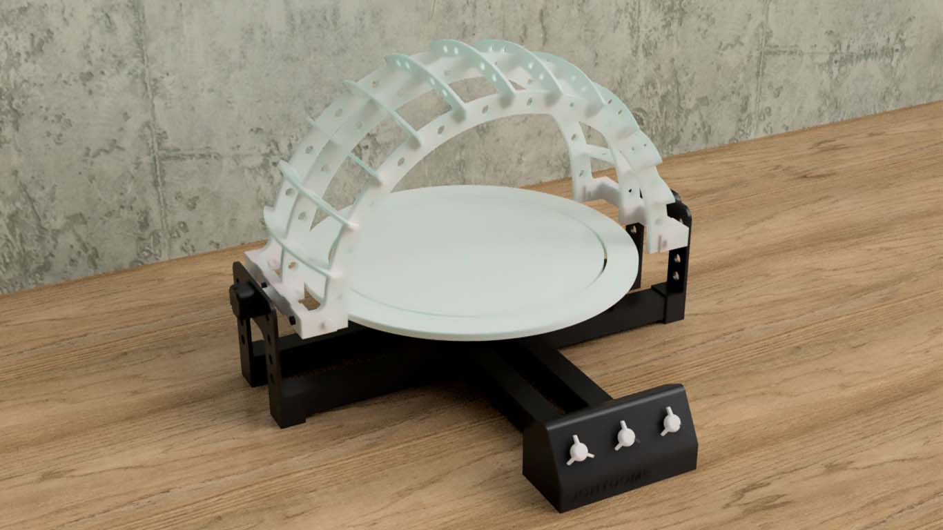
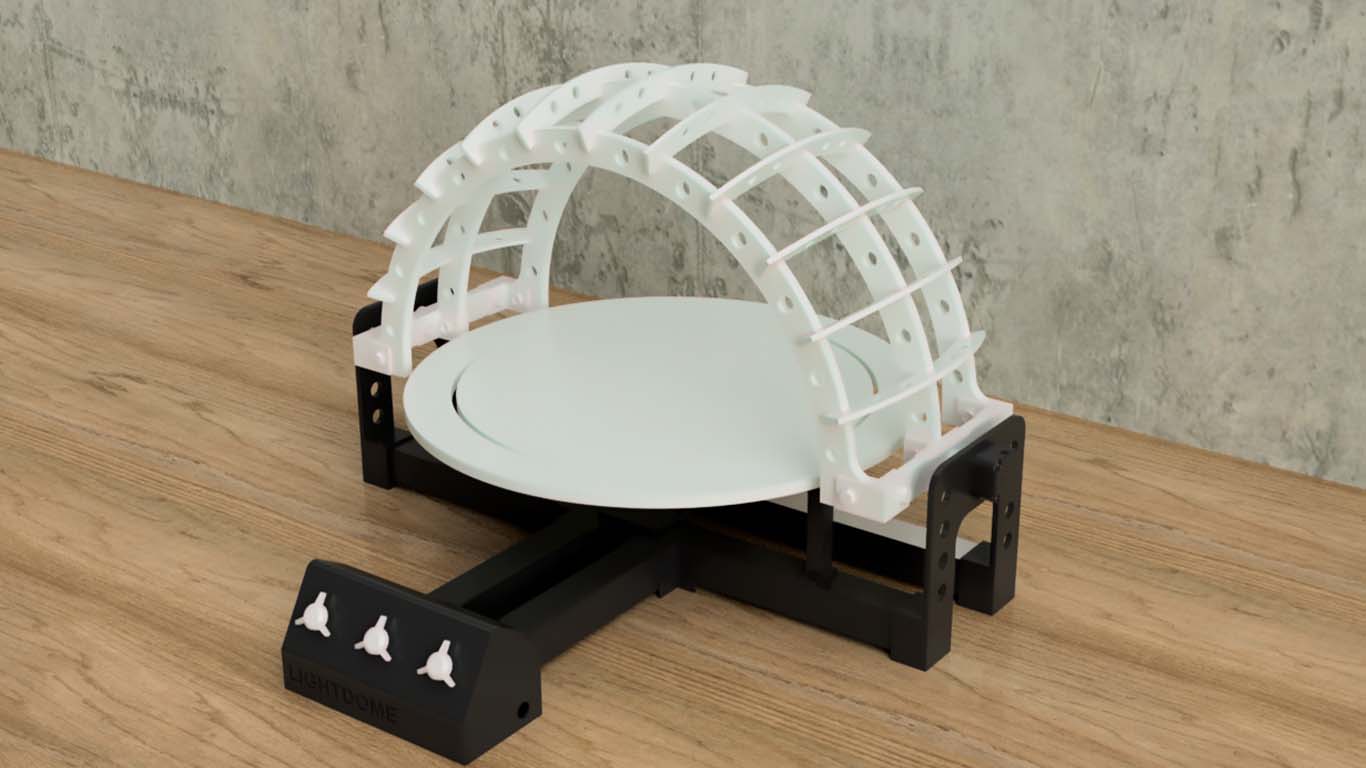
After making some sketches to improve the design and better understand the processes during the weeks, I proposed the final design that LIGHTDOM would have. The characteristics that I used were that it was LIGHT both in materiality and in perspective. Here the design process in FUSION
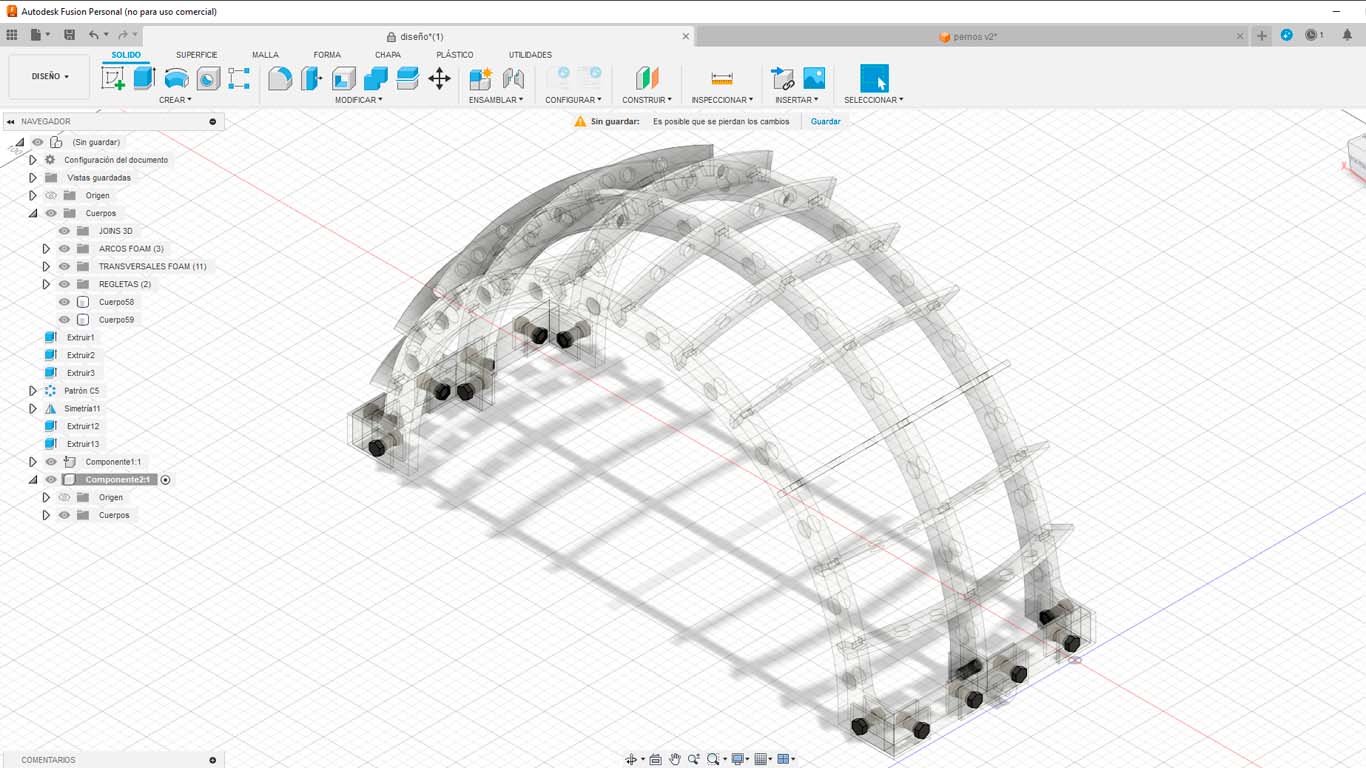
First, I began to develop the shape and characteristic of my bows. In this case, I tried to reduce the weight because I had verified with a model that it was very difficult to lift the arches as they were solid. Therefore, I made small holes in all of them to reduce the weight without damaging their structure.
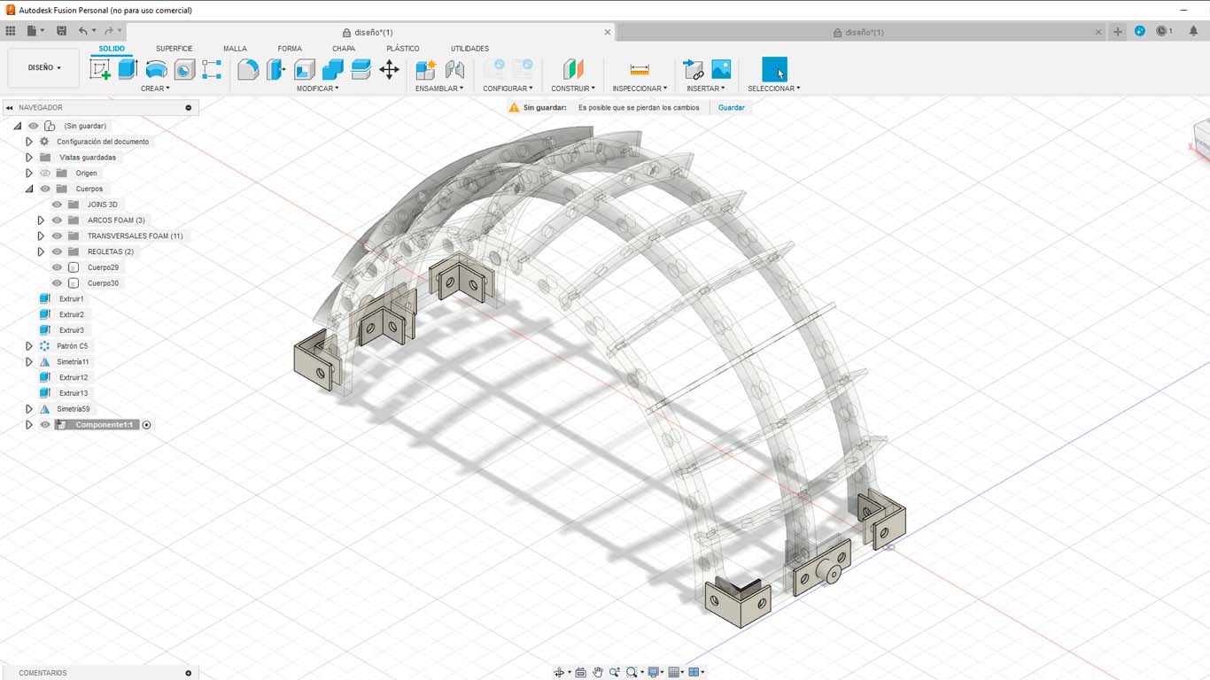
Then I began to design the joins that I will use to be able to connect all the parts that comprise the arch. These will be developed with 3D printing and white PLA filament.
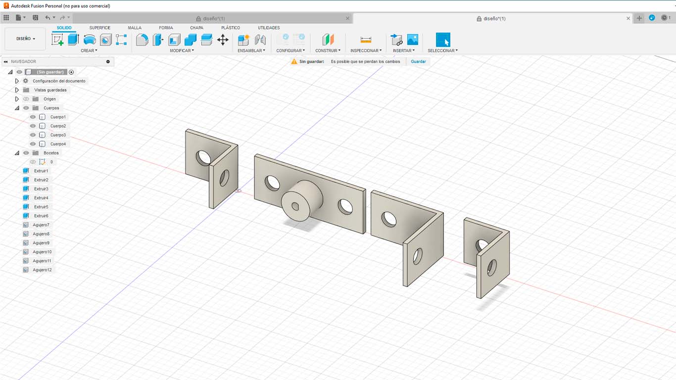
Here we can see the location of the joins that stabilize and structure the arches for their movement.
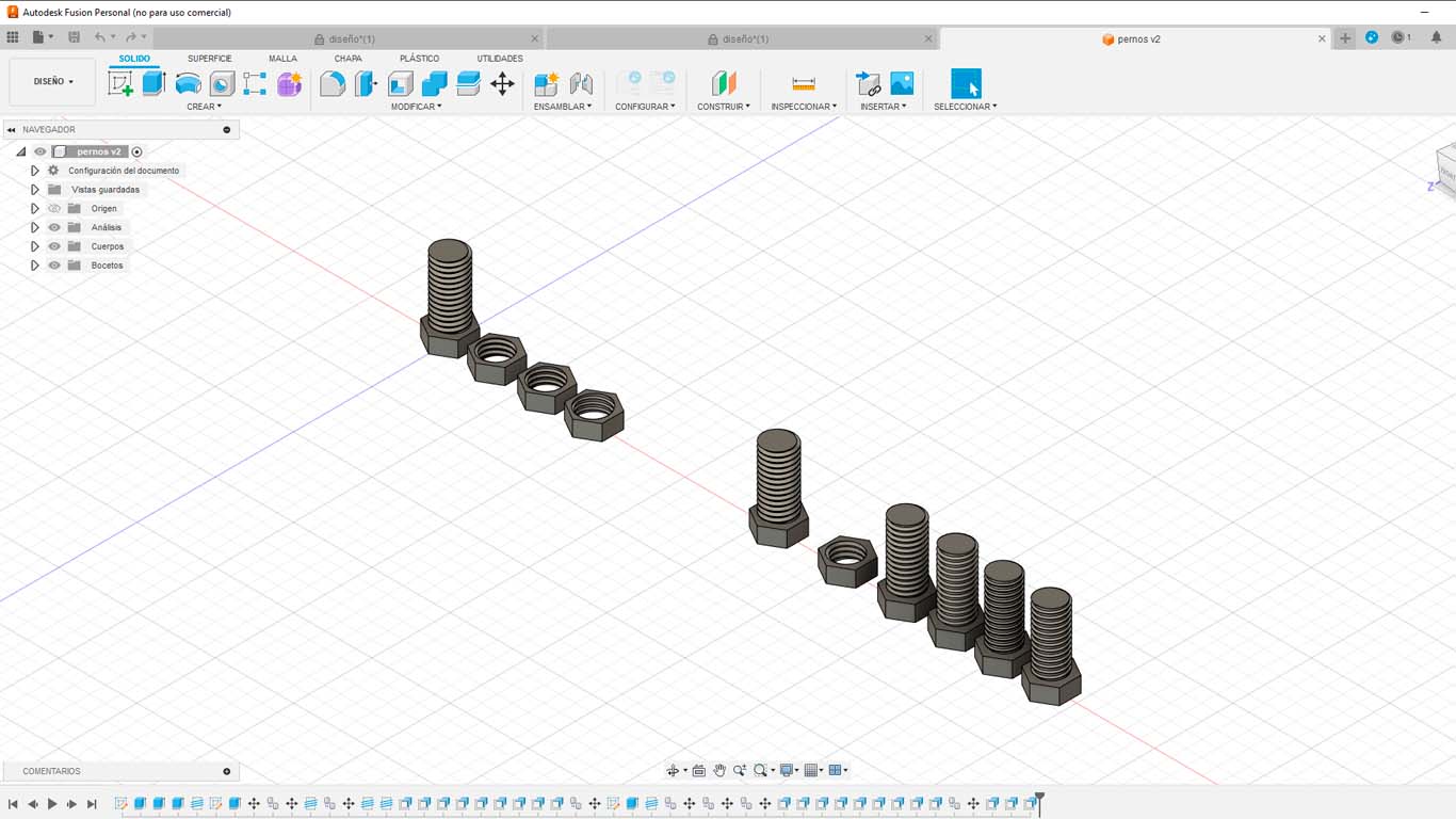
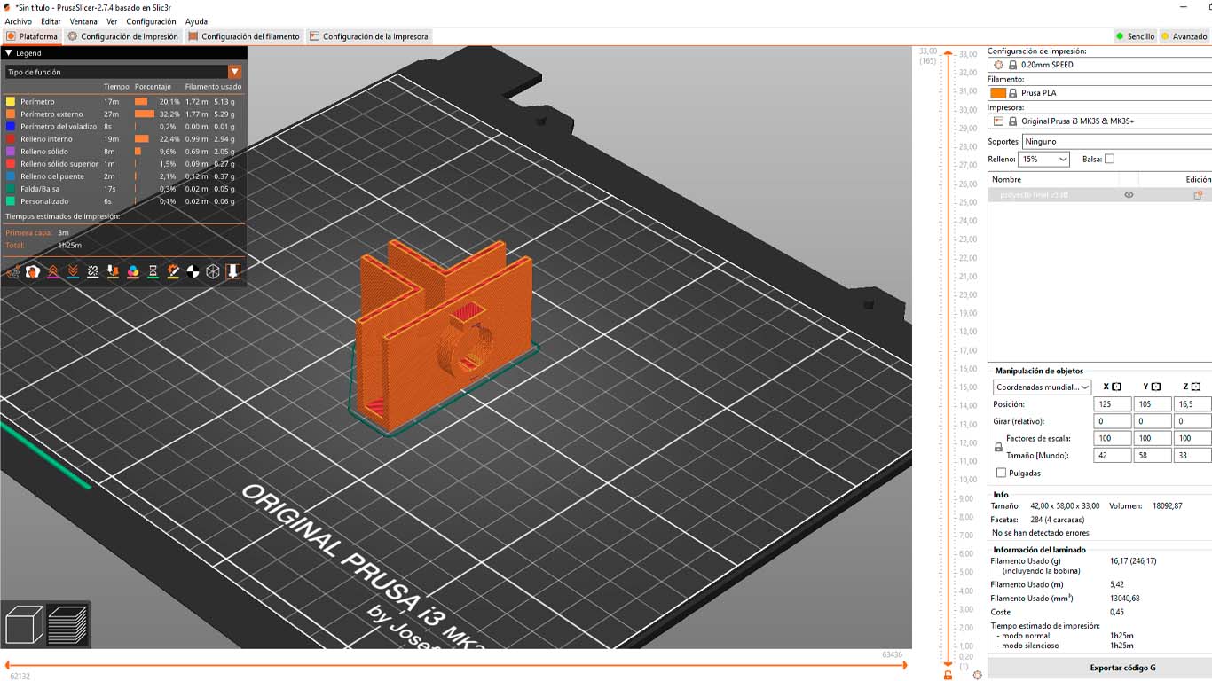
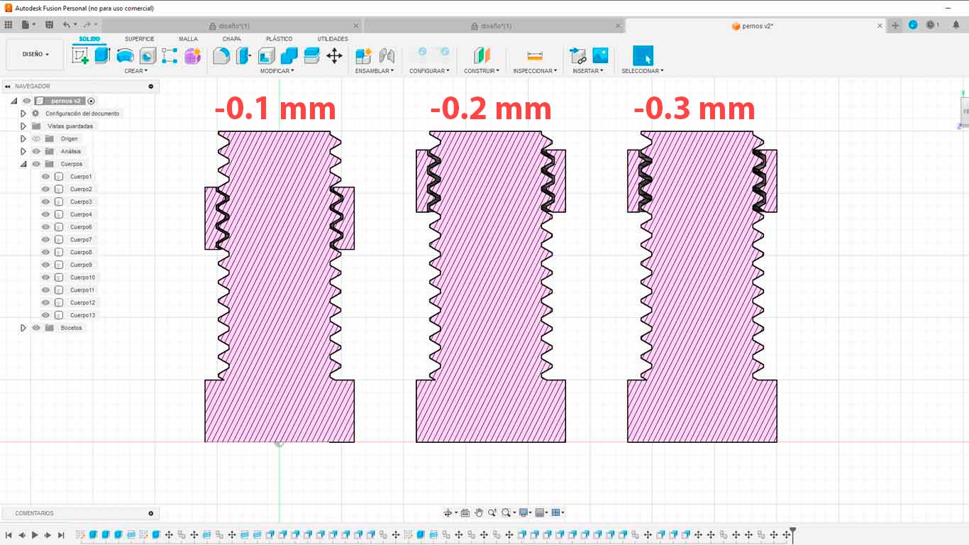
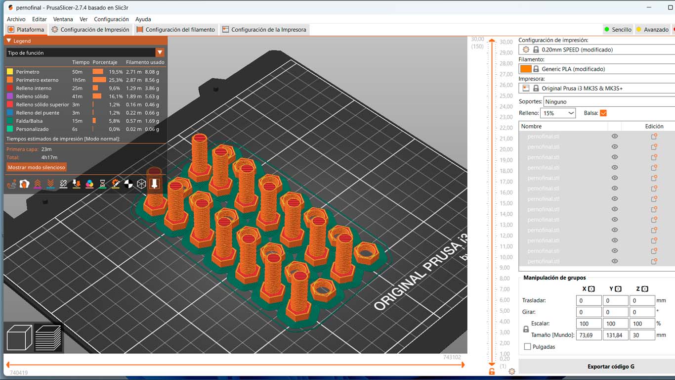
Then I also started designing the bolts and nuts for the joins that will also be 3D printed. Here is a screenshot of when I was modeling the bolts.
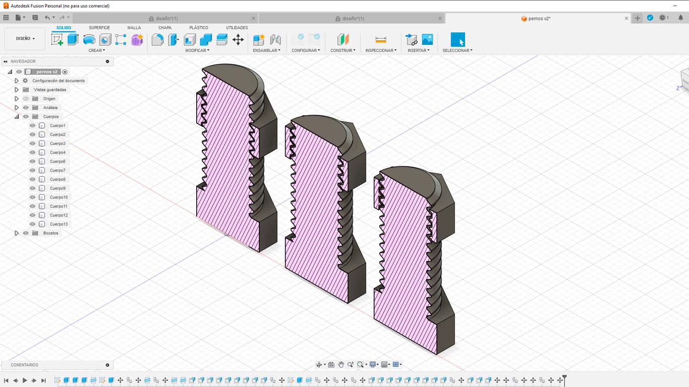
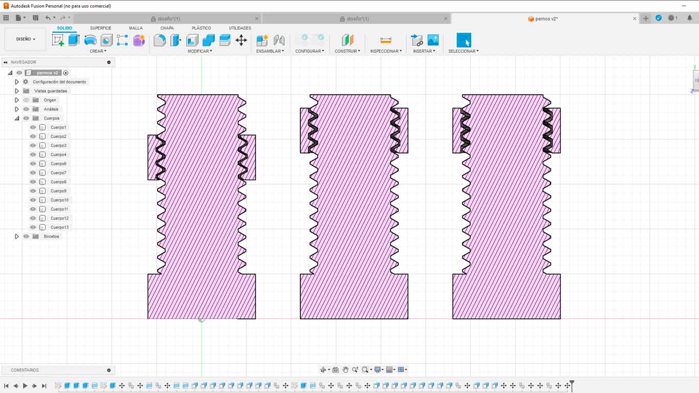
For the nuts and bolts to function correctly, I had to do a test beforehand to see if they worked. In my case I used the M10 measurement for the bolts since it is important to know the limitations and also the adjustment they have. Here is a screenshot of the 3 discounts I made to the bolt to know which one worked best with. For now, I will leave it like this, in week 5 of 3D PRINTING we will be able to see the test.
Finally, here is a screenshot of how all the designed bolts will go and will be made with 3D printing.
On the other hand, also design the part of the base structure that will support the entire arch. The idea is to generate a module that can support adhering the stepper motor using screws and can also serve as a base and connection of the aluminum that will go on the base.
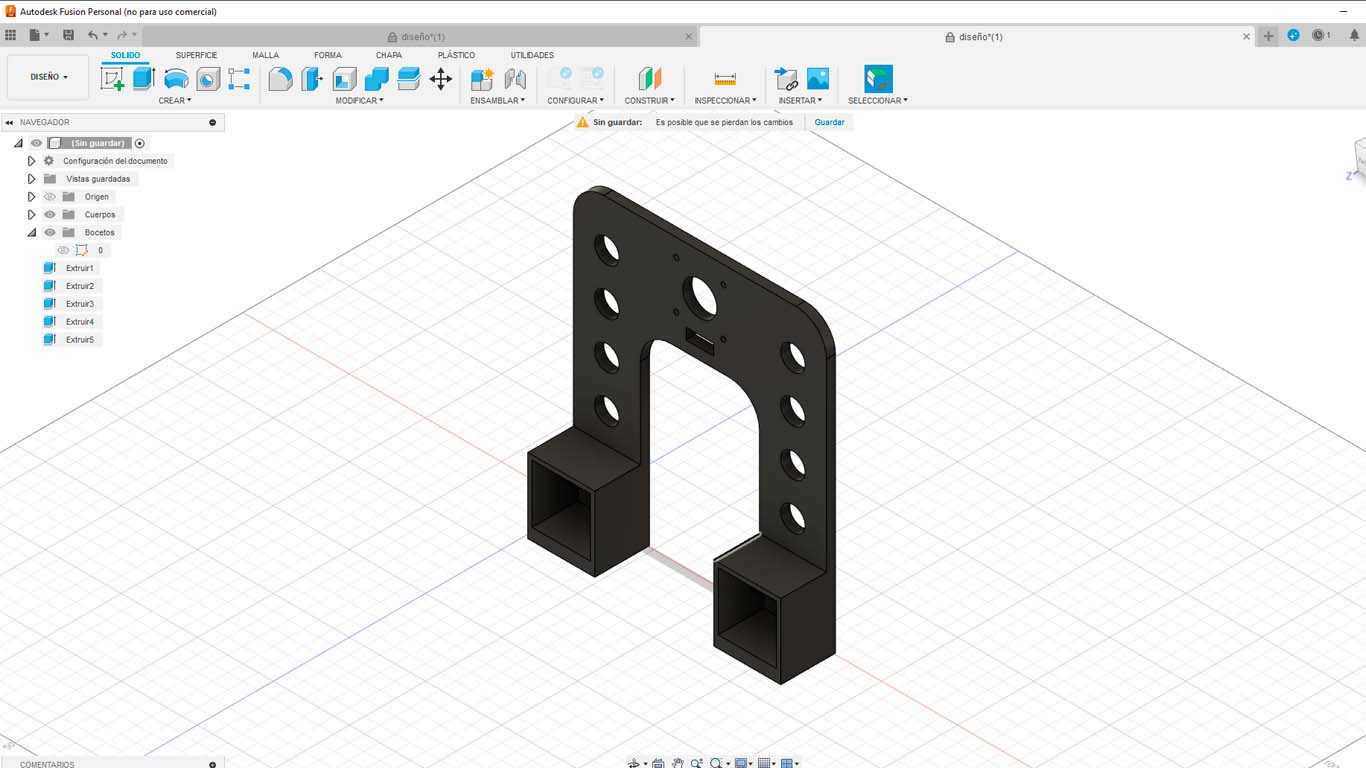
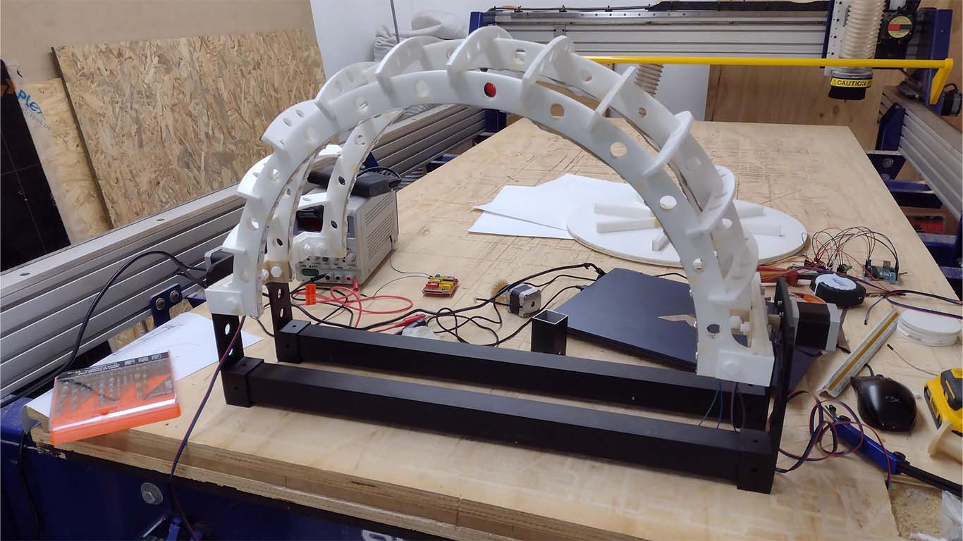
The first part of the base would be joined together using aluminum tubes to prevent it from being heavy and will have supports on the sides for both the step motors and also for the arches with black 3D printed elements. Here is a photograph of the idea.
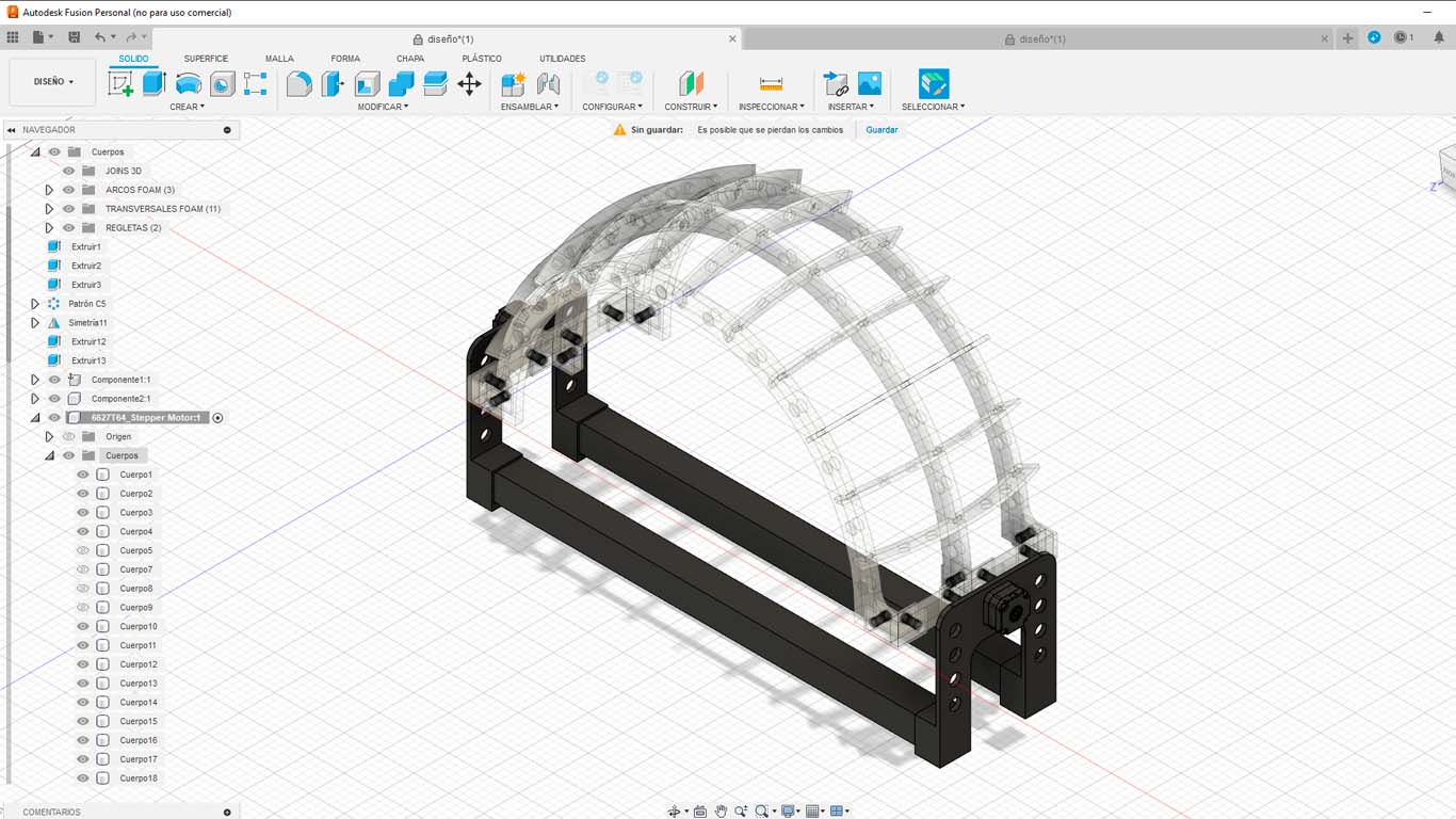
Likewise, 2 more aluminum rods are added to connect with the base of the project and it is to locate the controls and connection of LIGHTDOM, this will connect with a space where we will find the control components of the artifact.
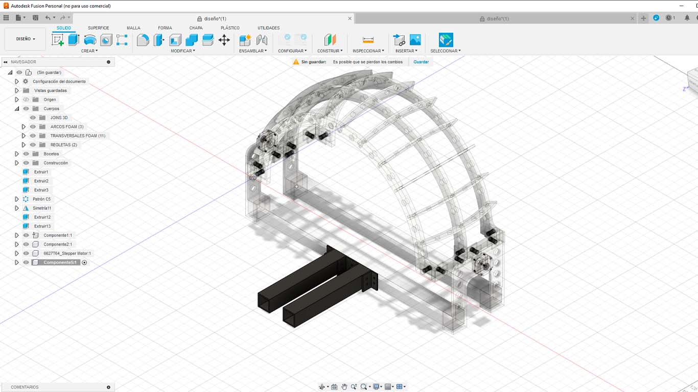
Finally, we added the control zone where we can manage the location of the arches, the rotating circular base and the location of the lights that will simulate the sun.
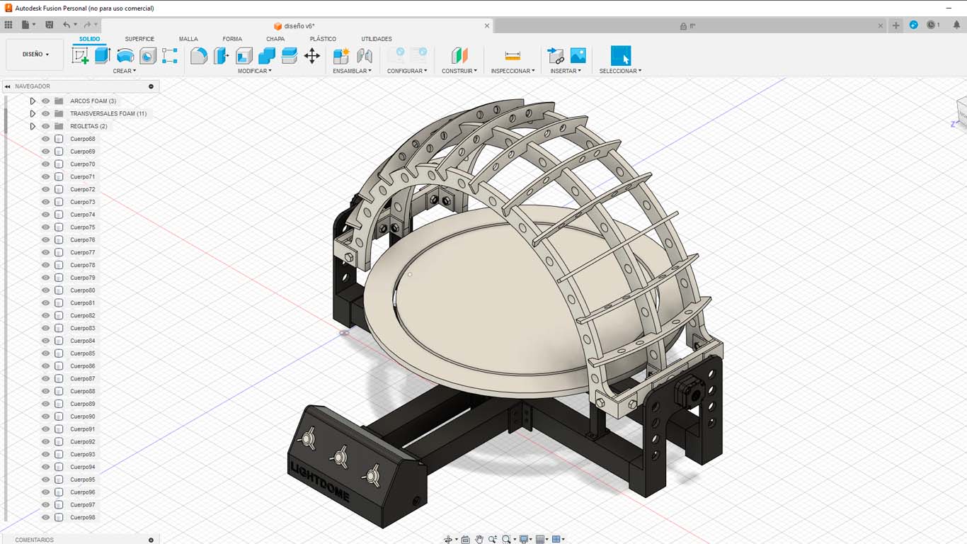
Here I leave some renderings that I made of my design and the final development of the shape of my project was not to first develop my design and only manufacture it. The process was spiral, where each part was developed between failures and successes that happened in the process.
COMPUTER CONTROLLED CUTTING
FIRST SPIRAL
The first spiral for my project was developed in week 16 since until this week I had not made much progress on the final project, but here is the link if you want to know more FIRST SPIRAL
FIRST MODEL
In week 3 we learned how to use the laser cutter along with other features that we must take into account, such as making pressure connections, which was important to learn. Therefore, for my final project I wanted to use CARDBOARD OR FOAM, which are lightweight materials so that the stepper motors can move it without complications.
In order to obtain a good result for my final project I had to make MODELS of my project using the laser to obtain the pieces quickly and at the same time be able to know the errors I was going to have along the way. Therefore, here I show you my process and what was obtained for my final delivery.
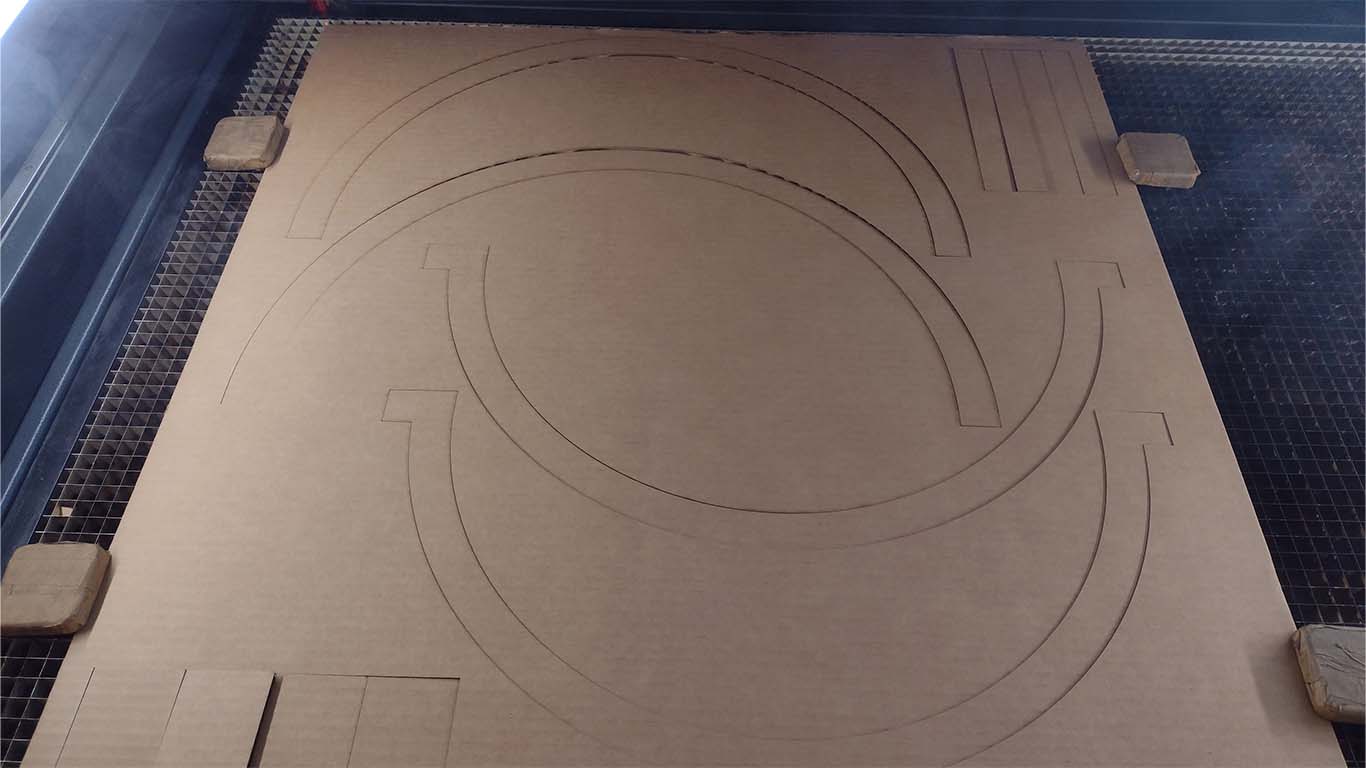
To begin the process I made the design of my final project to laser cut it in AUTOCAD . Where I wanted to analyze the size, weight and what my final project was going to look like. Let's remember that to achieve this we have to work in SPIRAL , so this process helped me a lot to understand the structure, mechanisms and how it was going to develop. Therefore, taking into account the measurements of the 4 mm cardboard sheets, I had my first model cut.
After obtaining the design, I had it laser cut taking into account the values made in WEEK 3 of the FAB ACADEMY. Here is a screenshot of the laser cut made for my final project mockup.
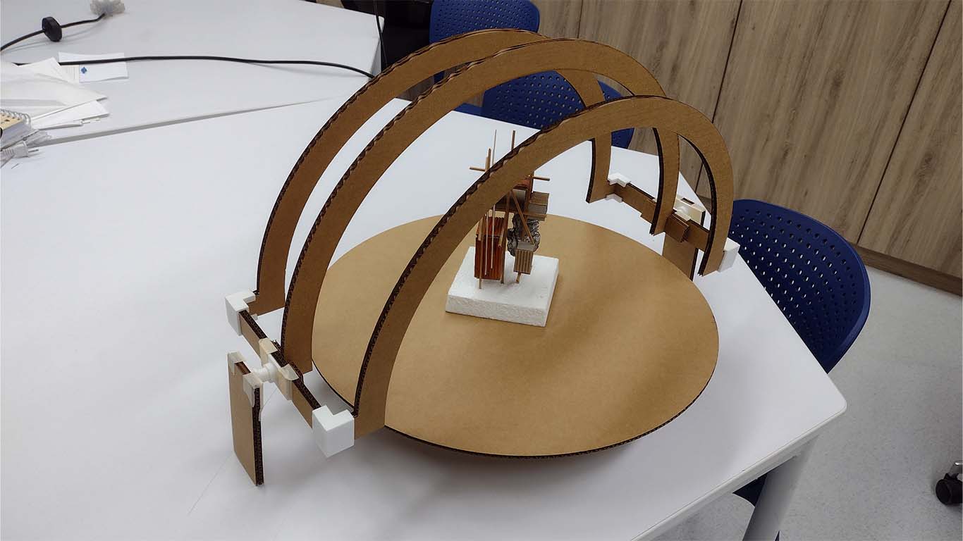
After obtaining the cut, I supported myself with some 3D prints that I was also testing of my joints and I began to make my mockup of my final project. Here are some screenshots of what it was going to look like and it helped me define some doubts I had.
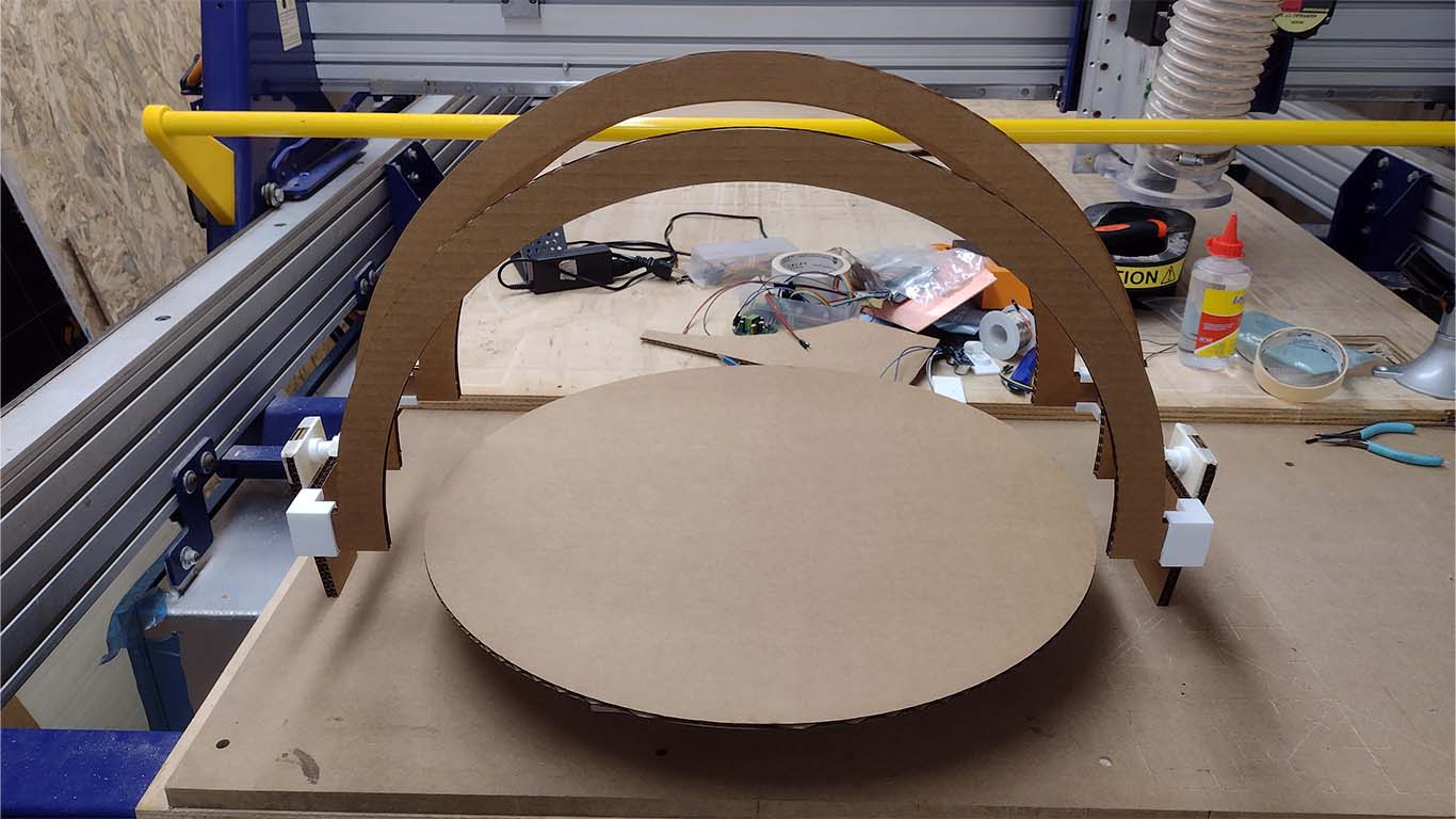

To complete my first spiral I wanted to make a simulation of the movement that my final project was going to have, checking the weight and movement. Here is a simulation video.
SECOND SPIRAL
Regarding the second spiral, it was developed during week 17, here is the link to the progress SECOND SPIRAL
SECOND MODEL
For my second spiral of the process, at the OPEN GLOBAL TIME they recommended me to use FOAM since it is a very light material and it could also help reduce the weight so that the motors can move it and also perhaps make a hole design to remove more WEIGHT to the entire structure of my arches. Therefore, I started designing in AUTOCAD and had it cut, here is the process.
First I started to calibrate the height of the laser 2 mm away from the FOAM so that it can cut and also avoid burning the material since it is very delicate.
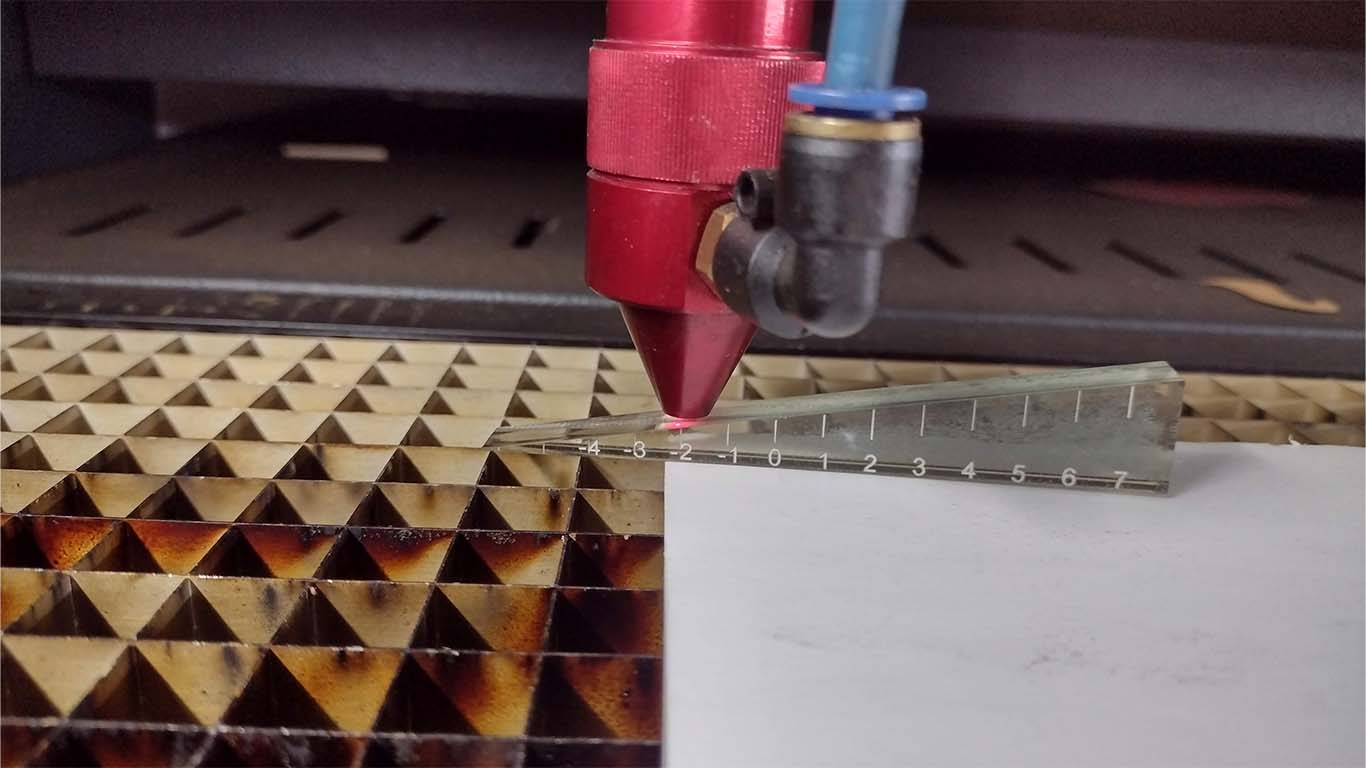
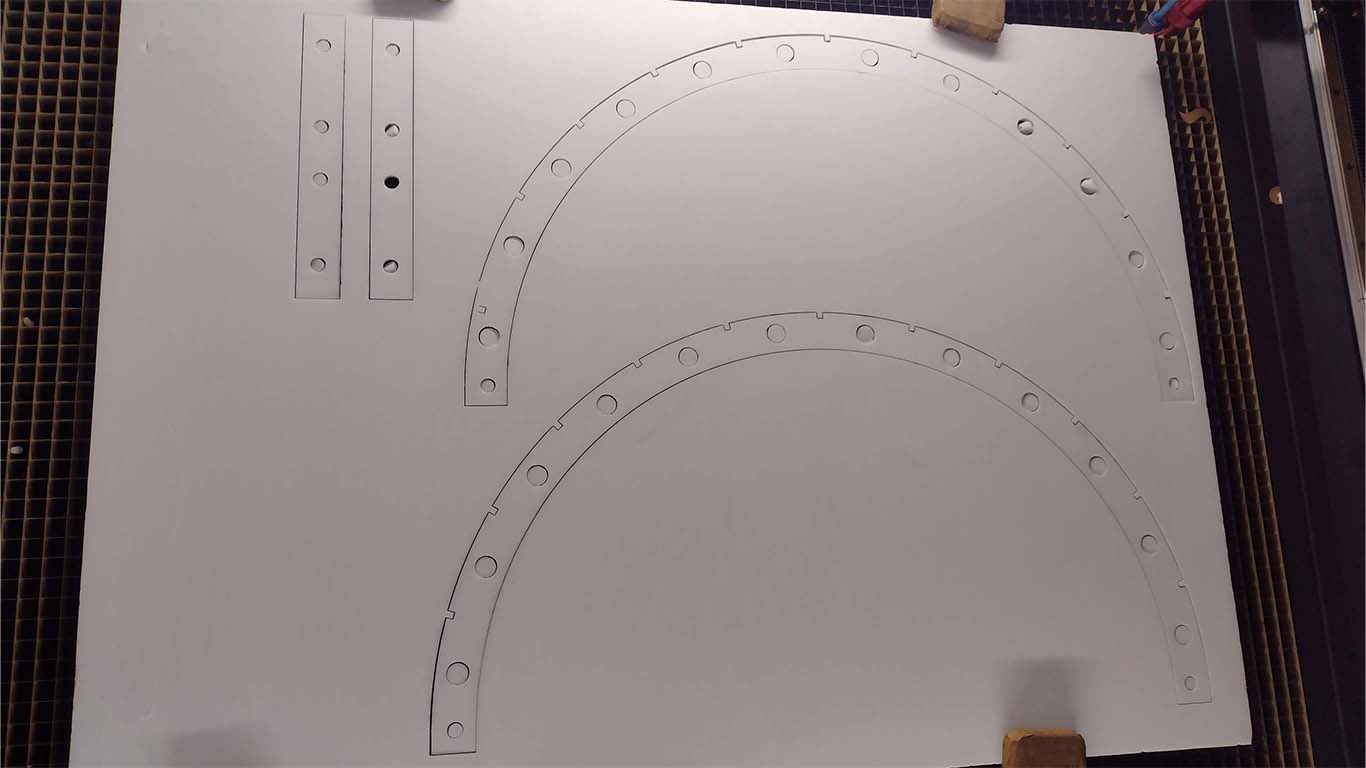
After calibrating and checking the speed with the laser power, I sent it to cut. Here is a video of the cutting process.
Here is a photograph of the result where the material did not burn and came out very well.
However, when it came to assembling and manipulating the material, I realized that the TRANSVERSAL ARCHES that tie the 3 main arches together were very thin, and when I put pressure on them during assembly, they broke. Here's a screenshot of how it broke.
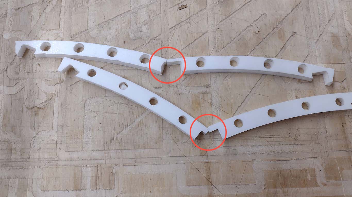
So I armed myself with those who withstand the pressure, but I didn't like the way my final project proposal looked. Here is a screenshot of the first result.
So I made the decision to make them thicker so they could fit correctly into the main arches since they had small cuts to connect them under PRESSURE.
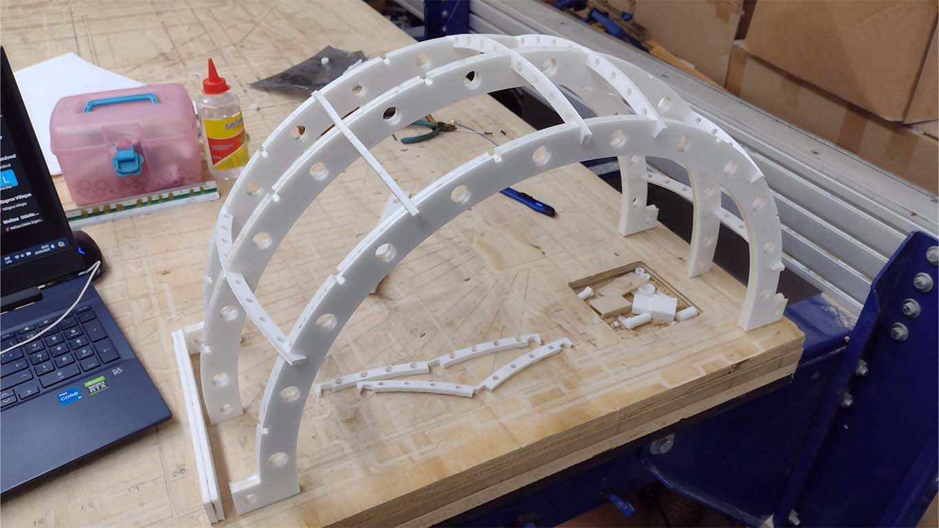
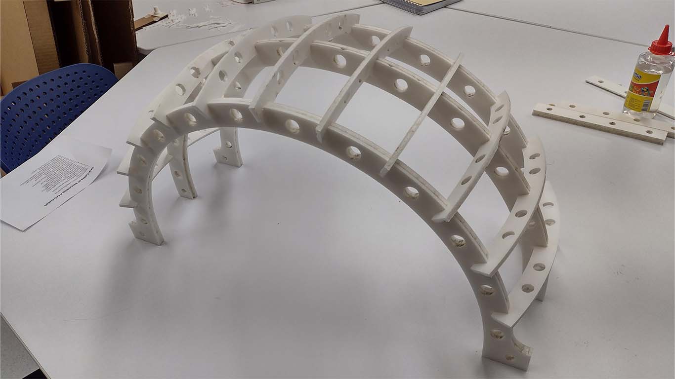
And now I was able to assemble my entire arch structure normally, where everything fit very well under pressure and also supported me with the first spiral of my 3D PRINTING , which was to develop the joints. Here is my first FOAM model. This model helped me a lot to carry out the other processes such as MECHANICAL DESIGN, 3D PRINTING AND ELECTRONIC DESIGN.
THIRD SPIRAL
The third spiral was developed in week 18 and here I leave the link so you can learn more about what was developed THIRD SPIRAL
For the delivery of my final project, I made a new cut of the entire arch structure because my model of the 2nd spiral had mistreated it, so I had used it to develop the other processes and I also added some improvements to the design.
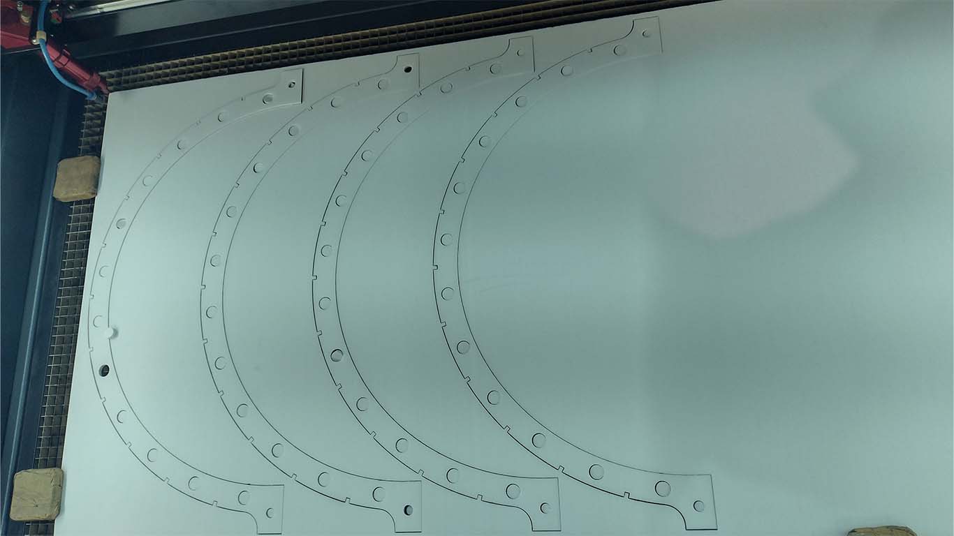
For this reason, I separated each part of what my project includes, together with the rotating base and everything I occupy in 4 SHEETS OF FOAM . Here is a screenshot of the autocad where I locate each part that comprises my project and ordered it to be cut.
After knowing the speed, distance and power of the laser, I had everything cut for my final project.
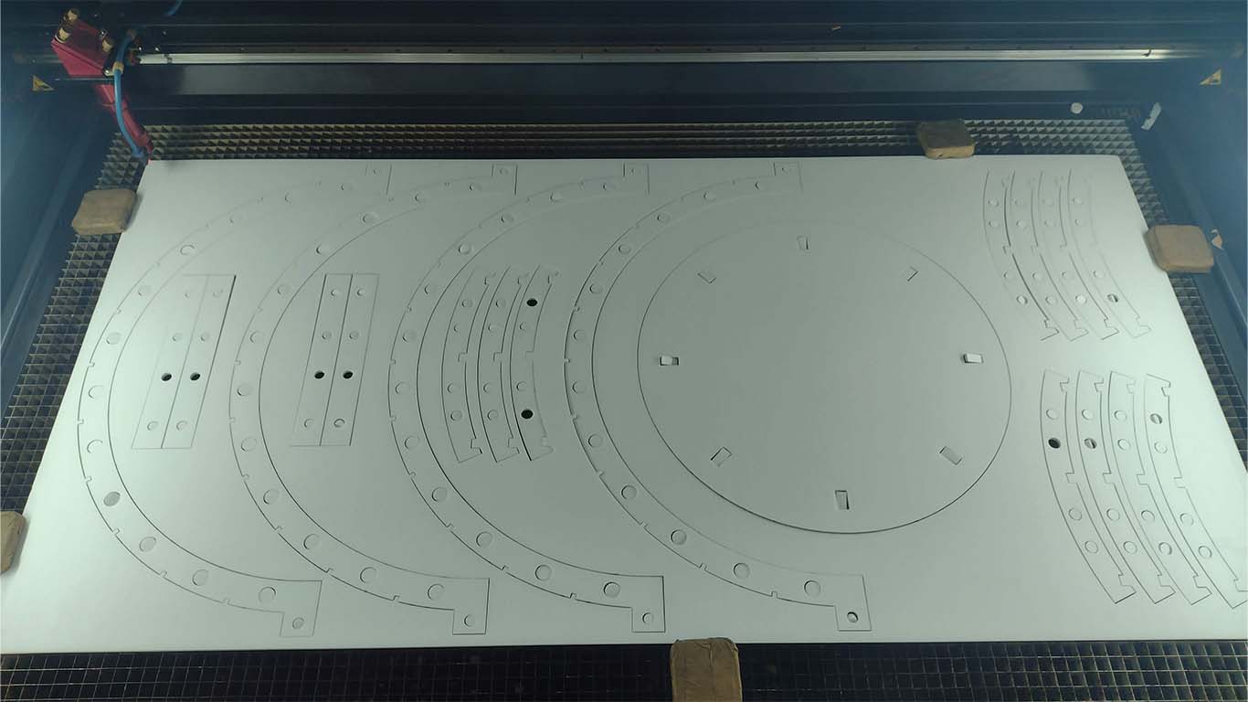
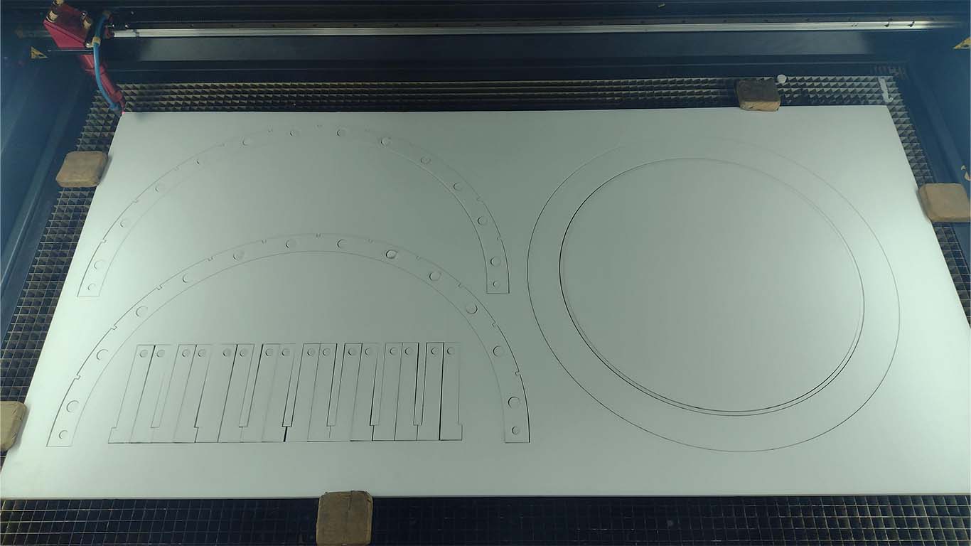
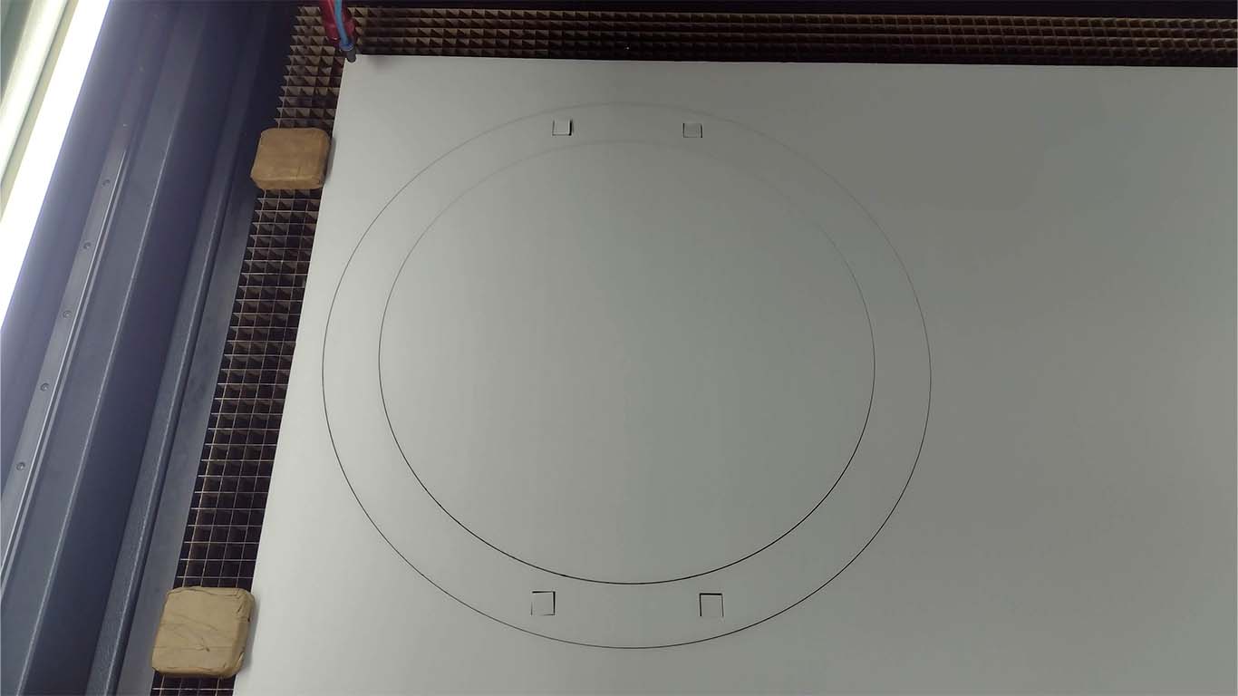
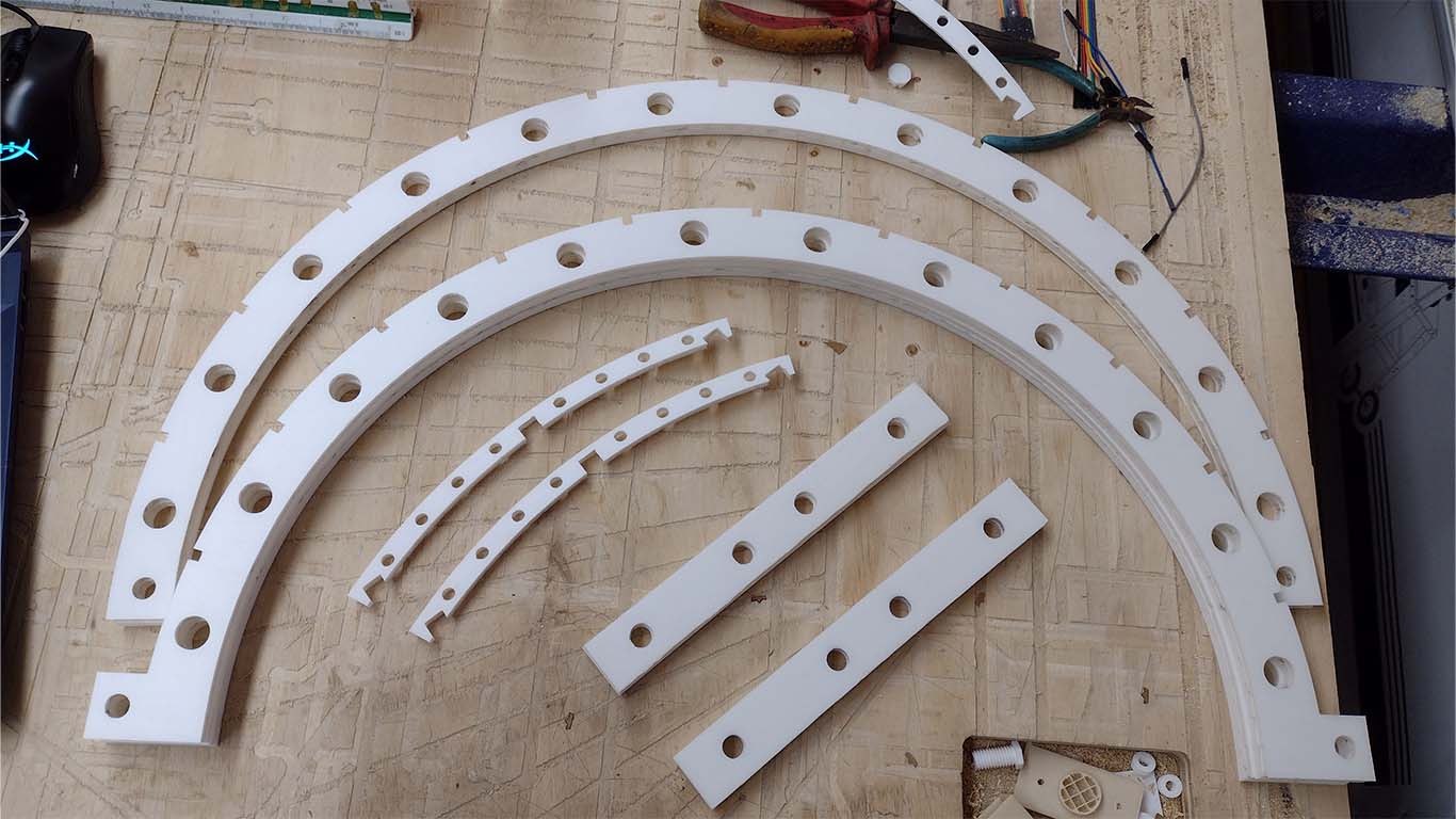
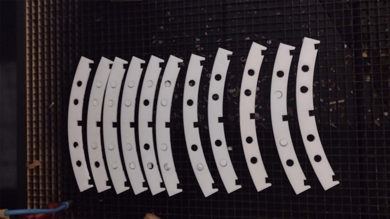
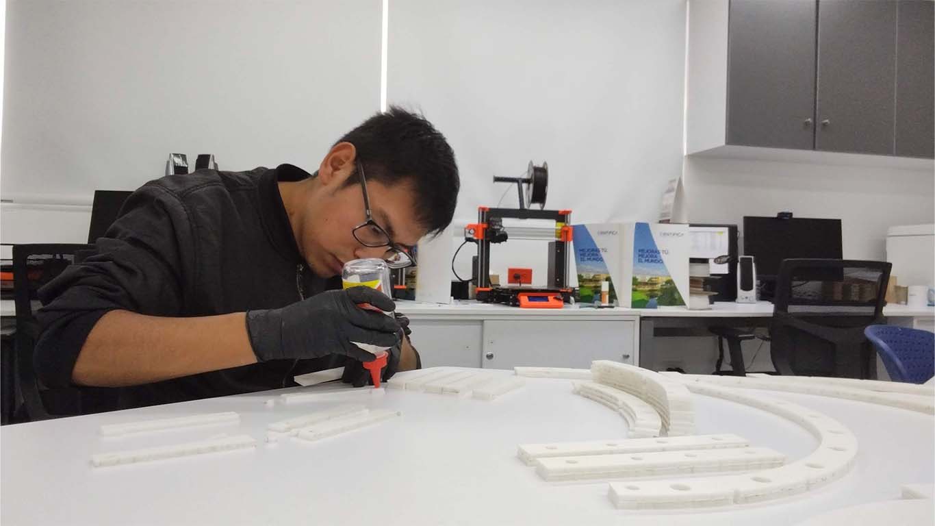
After having all the pieces cut, I began to glue them with silicone to be able to assemble the entire final structure of my project.
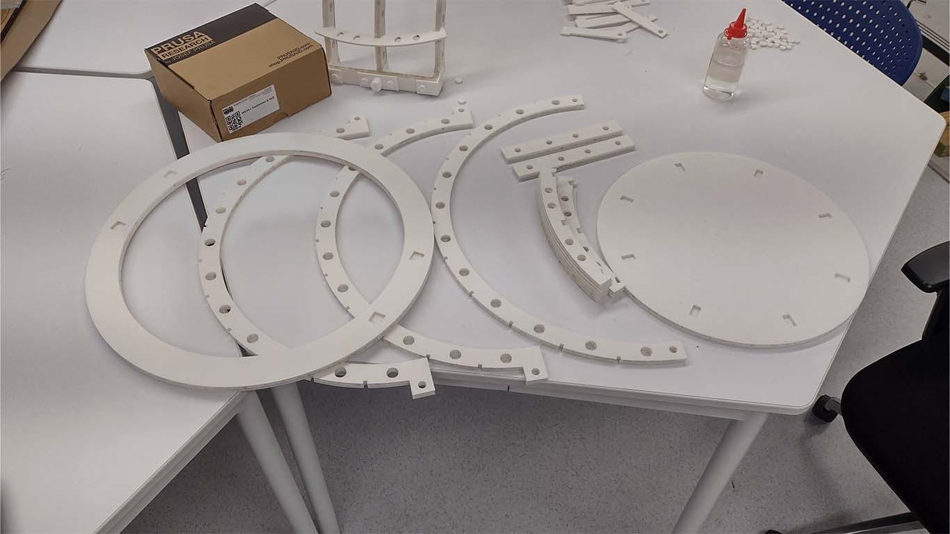
Here is a photograph of all the pieces ready for assembly and assembly for me the final delivery of my project.
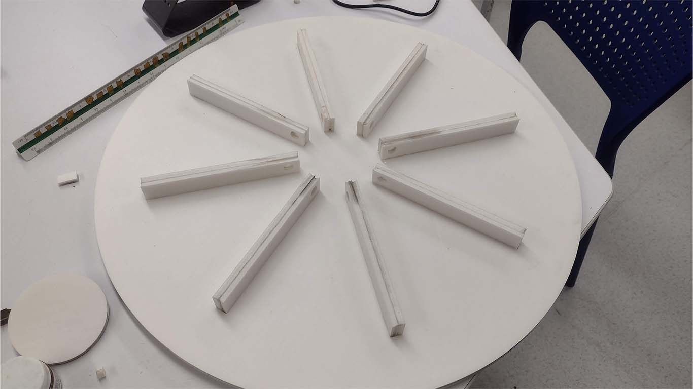
Finally, after assembling the entire structure of my arches and the circular base, I began to assemble my project that I had already developed in PARALLEL with the other processes. Here is a photograph of the assembly for my final delivery.
3D PRINTING
FIRST SPIRAL
The first spiral for my project was developed in week 16 since until this week I had not made much progress on the final project, but here is the link if you want to know more FIRST SPIRAL
ARCH AXES
For 3D printing, work was also done in PARALLEL to the other processes. In this case I started by developing the AXES of my first models, both made of cardboard and wood.
I started developing my axles separately, that is, the axle and support were separate without belonging to a single set and I could see that it did not work since the female part of my axle was very short, this applied to my cardboard model.
Here is a photograph of my model with the axis and first test of joints for the structure of the arches.
Another problem I discovered was the way the shaft was going to move the entire arch structure and how it was going to attach to achieve the goal. So I did my first snap test, where the cardboard was only going to fit in the space left by my 3D PROPS. However, it didn't convince me because the arches came off and there was no way to hold them except with rubber, but for the final project I didn't want it to simply be using rubber.
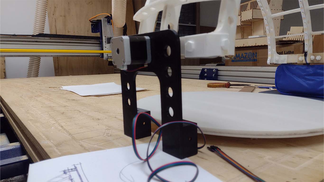
On the other hand, I also worked on the fit of my stepper motor and my axis in 3D printing, the idea was to obtain the exact measurement so that the stepper motor axis can fit and at the same time move the entire structure. Here is a photograph of the quick test for the stepper motor fitting.
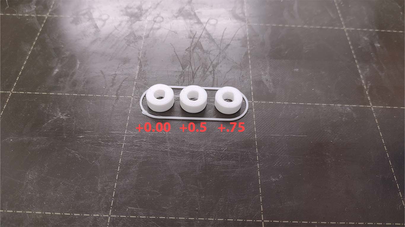
After doing the test, I concluded that the best fit measure is the +0.5 mm original diameter of the stepper motor shaft, where it entered under pressure and at the same time fit correctly, after having the result I went on to print my axes for the next tests .
After having my axes, I started to carry out a test with my stepper motors to see how they worked, everything was going well but they had torque errors that I had to improve. Here is a screenshot during the test.
3D BOLTS
On the other hand, I also began to develop the joining accessories for my entire arch structure, which I also wanted to develop with 3D printing. For this reason, I began to perform tests on bolts that would help me achieve the pressure I needed without using another type of adhesion and that would have better aesthetics. So first design the bolts in Fusion, along with their respective discounts.
Watching some reference videos and also what was done in week 5 of 3D printing, I made the discounts to 0.1; 0.2 and 0.3 the circular teeth of each bolt to find the best option.
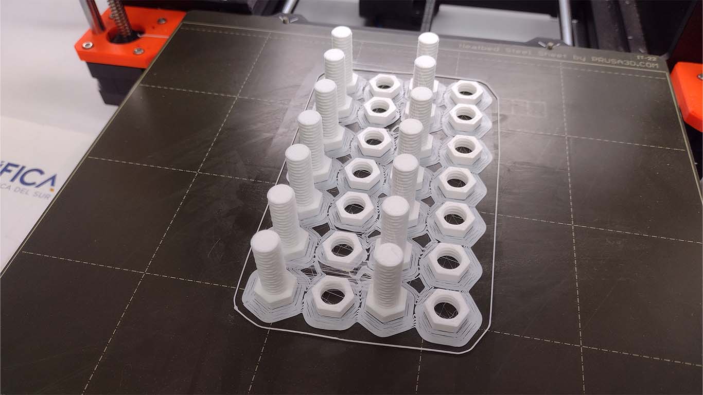
To find the best bolt test result, I had to print the test. However, I had a problem with the 3D printer as it had a jam problem and my entire test went wrong. Here is a photograph of the problem.
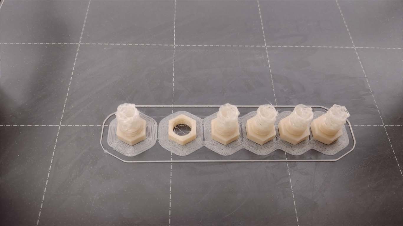
I sent it to print again after cleaning the 3D printer's extruder and changing the filament since they informed me that the filament I was using was in poor condition. So I sent it to print with another filament but I forgot to configure the RETRACTION factor, but since it is a pressure test, it does not affect much and it helped me see what discount value I had left for my project. Here is a screenshot of the impression.
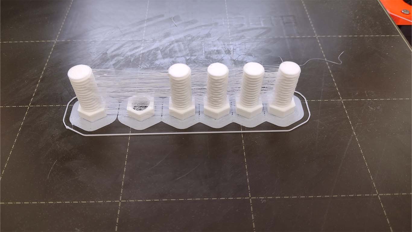
After printing, cleaning the filament residue, I was able to verify which value is the most functional both in terms of pressure and operation of the bolt and nut, and here are some conclusions:
- 0.1 mm: The bolt and nut had problems when adjusting because they did not fit easily, where the circular teeth of the bolt were damaged and at the same time they did not have the ease of pressure because it was very tight.
- 0.2 mm: Both bolt and nut worked well since the pressure and adjustment were correct, the adjustment was not that complicated and that was the intention.
- 0.3 mm: The bolt and nut worked fine but didn't fit well, sometimes didn't work and came off, so it wasn't what I needed.
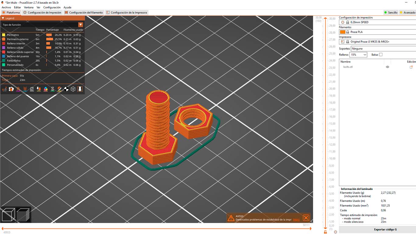
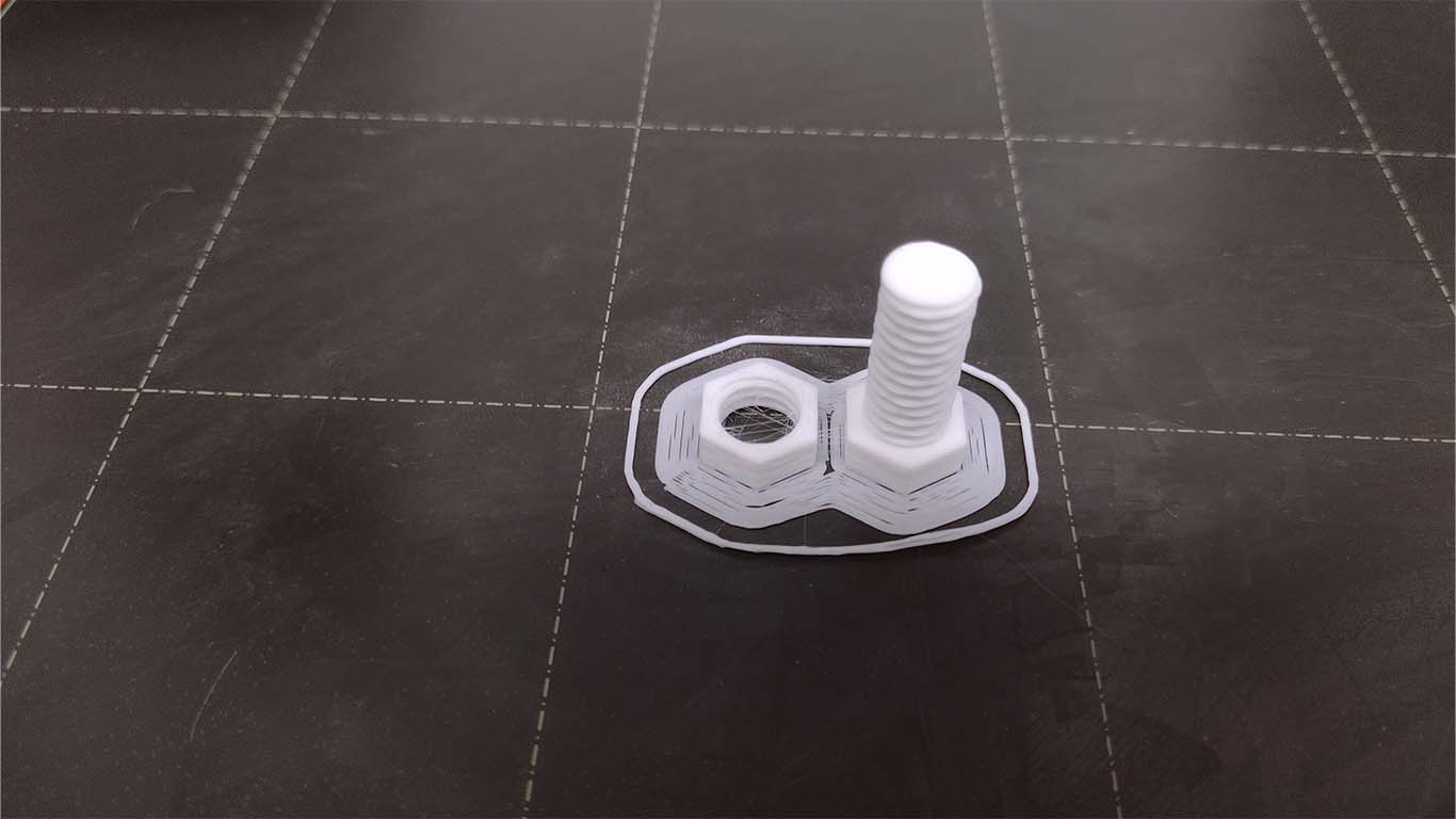
After testing, I was able to conclude that the best option for the bolts was to deduct 0.2 mm on the circular teeth of the bolt and the adjustment worked correctly. Here's a quick impression of the bolt and nut with the discounts made.
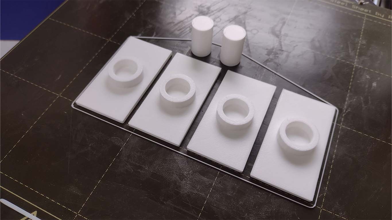
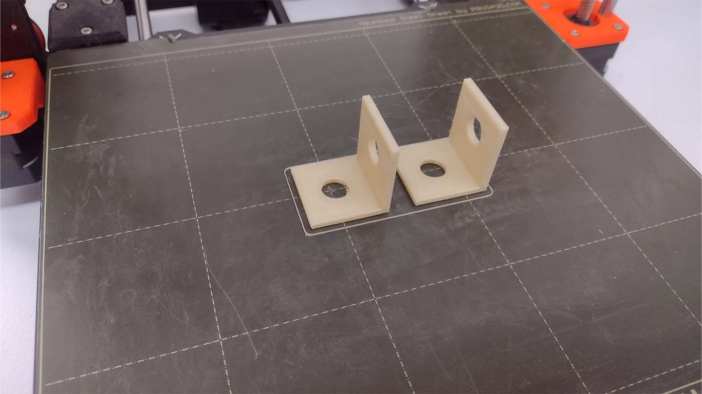
On the other hand, also for this first spiral I made my connection accessories with the corresponding holes to be able to fit the bolts and nuts that I am going to use from 3D printing to structure the part of my arches. Here is a photograph of an accessory that will be used for my second spiral.
GEARS AND SUPPORT
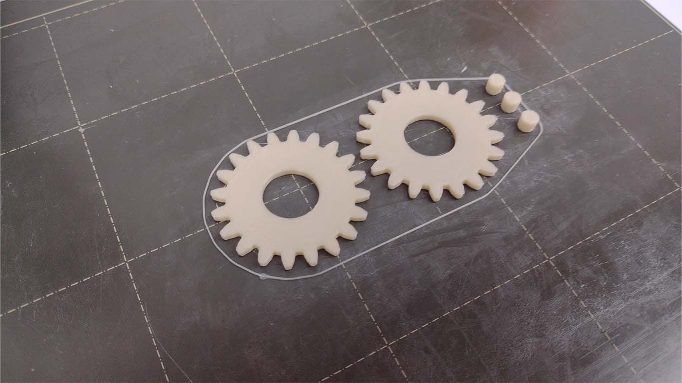
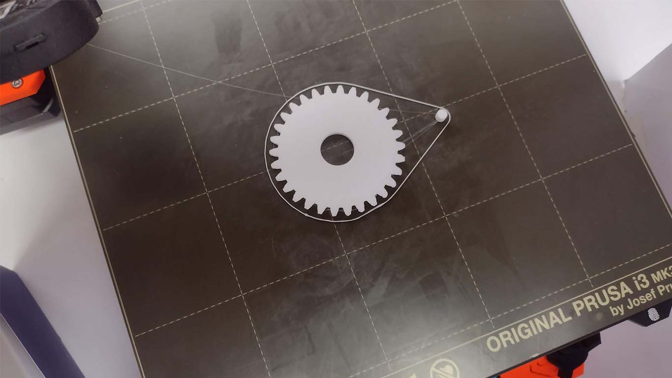
Finally, to complete the first 3D printed spiral, I carried out some tests on gears and the support of my entire structure of my arches. I began by carrying out a gear test, checking the size of the teeth and diameters that were going to move the circular base and, on the other hand, the base of the entire structure of the arches, where I carried out a test.
For the base and support of the entire structure I had to make a design where the stepper motors can be placed and that the structure can withstand the movement and vibration that they could perform. Therefore, for my first spiral I wanted to place them at the bottom due to the weight, but I was not convinced by the size of the arches and the way the movement was going to work.
The base was going to have all the dimensions of the stepper motor so that they can be bolted and secured with screws. Furthermore, the idea was to generate a base so that the stepper motor could rest, but for reasons of design and operation of Lightdome, it was not possible for it to be located in that position. Now we go for the 2nd spiral.
SECOND SPIRAL
Regarding the second spiral, it was developed during week 17, here is the link to the progress SECOND SPIRAL
AXIS AND ARCH ACCESSORIES
For the second 3D printing spiral, the goal was to have all the pieces to assemble my final project prototype model. Therefore, I began printing all the components that comprised the structure of the arches, where I began to print the accessories for the strip and the arches, together with the axes that would be fitted into the axes of the stepper motor.
Likewise, I began to 3D print all the bolts and nuts that I would need to adjust the entire structure and with all the discounts made for its correct adjustment and pressure. In the end I used about 14 bolts and bolts.
For my first mockup, I started using all the printed elements and here is a photograph of how it turned out.
GEAR SYSTEM TO CIRCULAR BASE
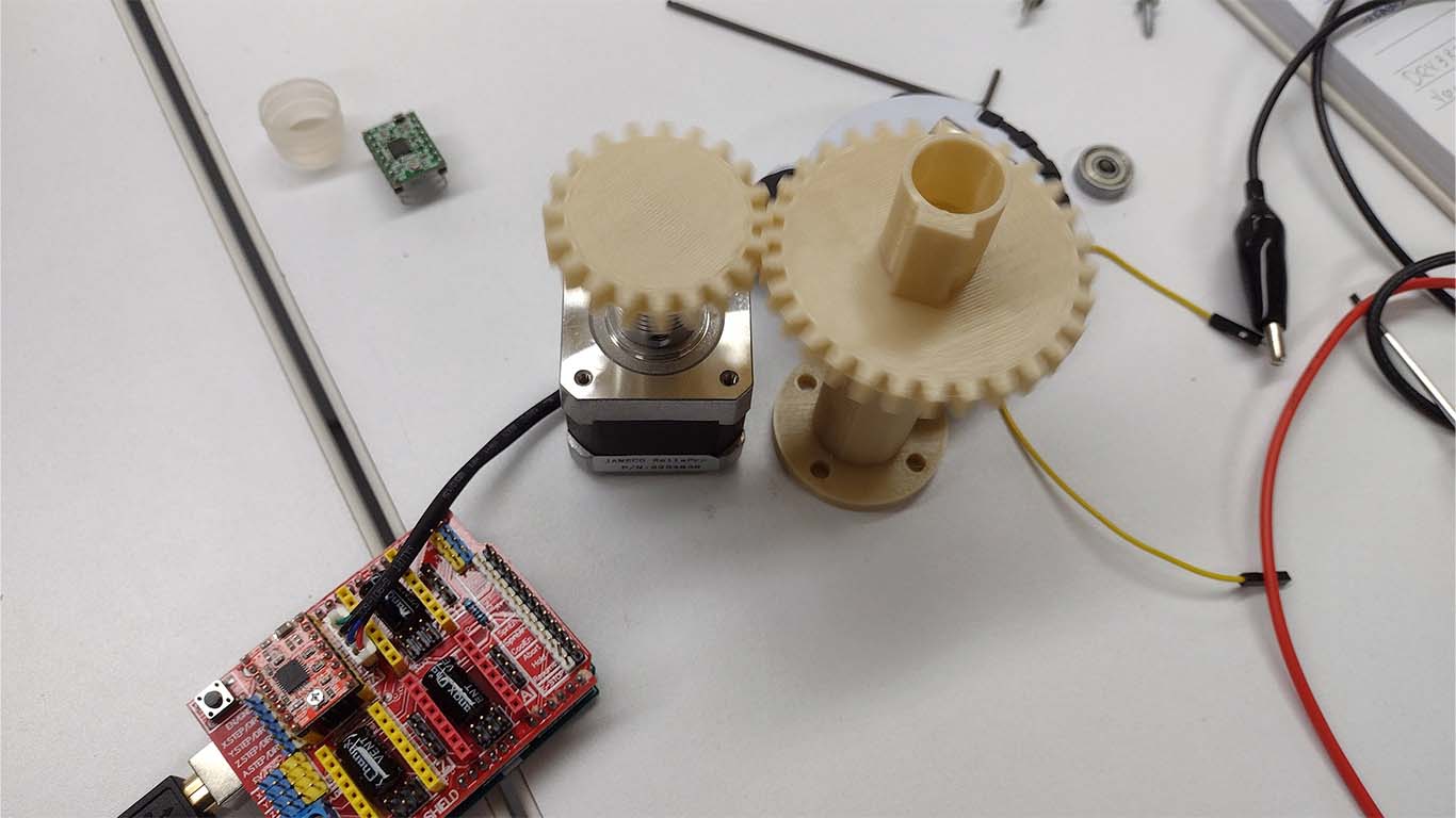
On the other hand, the gear system that was going to move the entire circular base where the architectural models would be placed was also worked on. Therefore, we began to work with several 3D printed pieces to achieve movement. Here the process of the 2nd spiral.
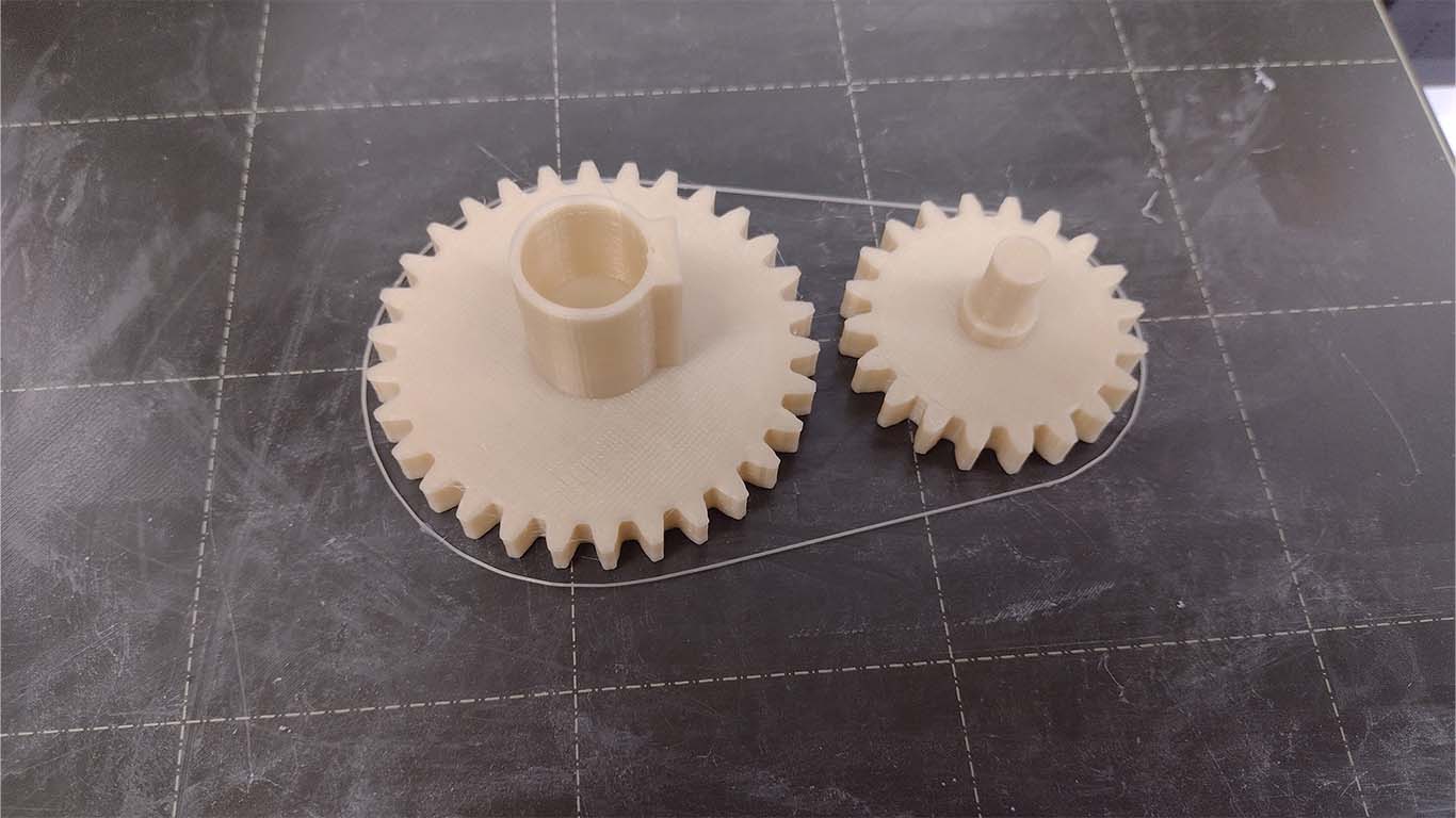
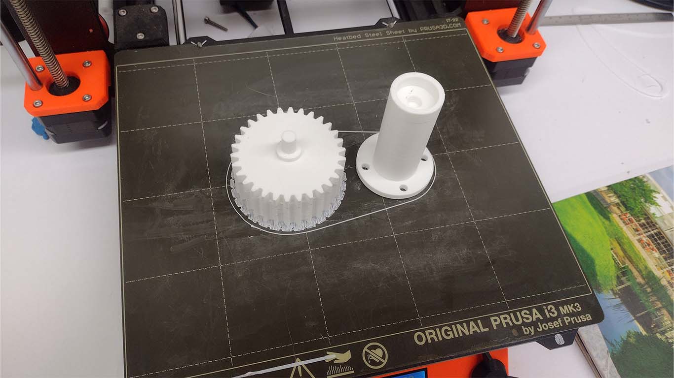
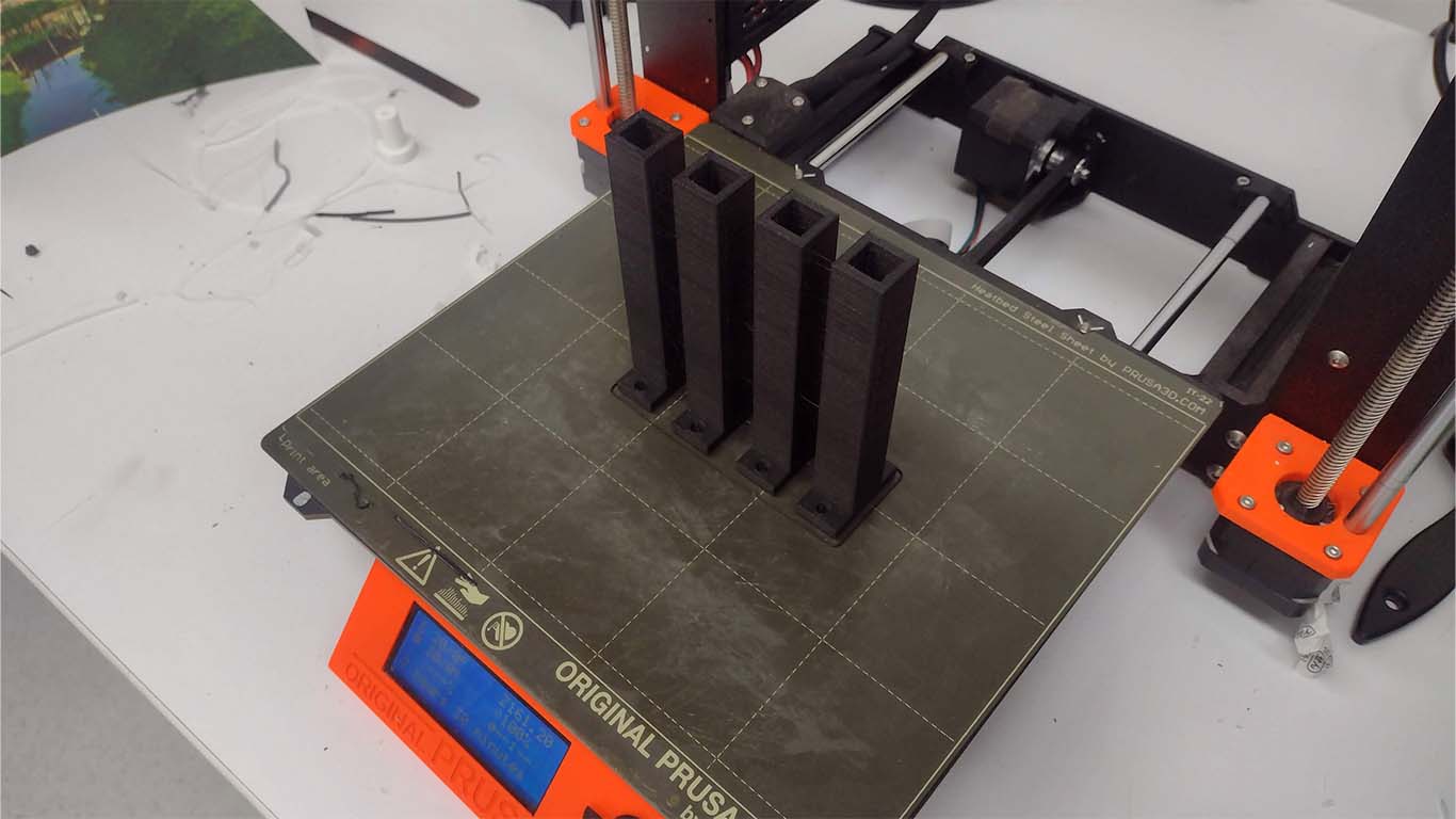
First, the gears began to be printed, which are composed of 2 gears that were going to be located at the bottom of the circular base and that were going to carry out all the mechanical movement.
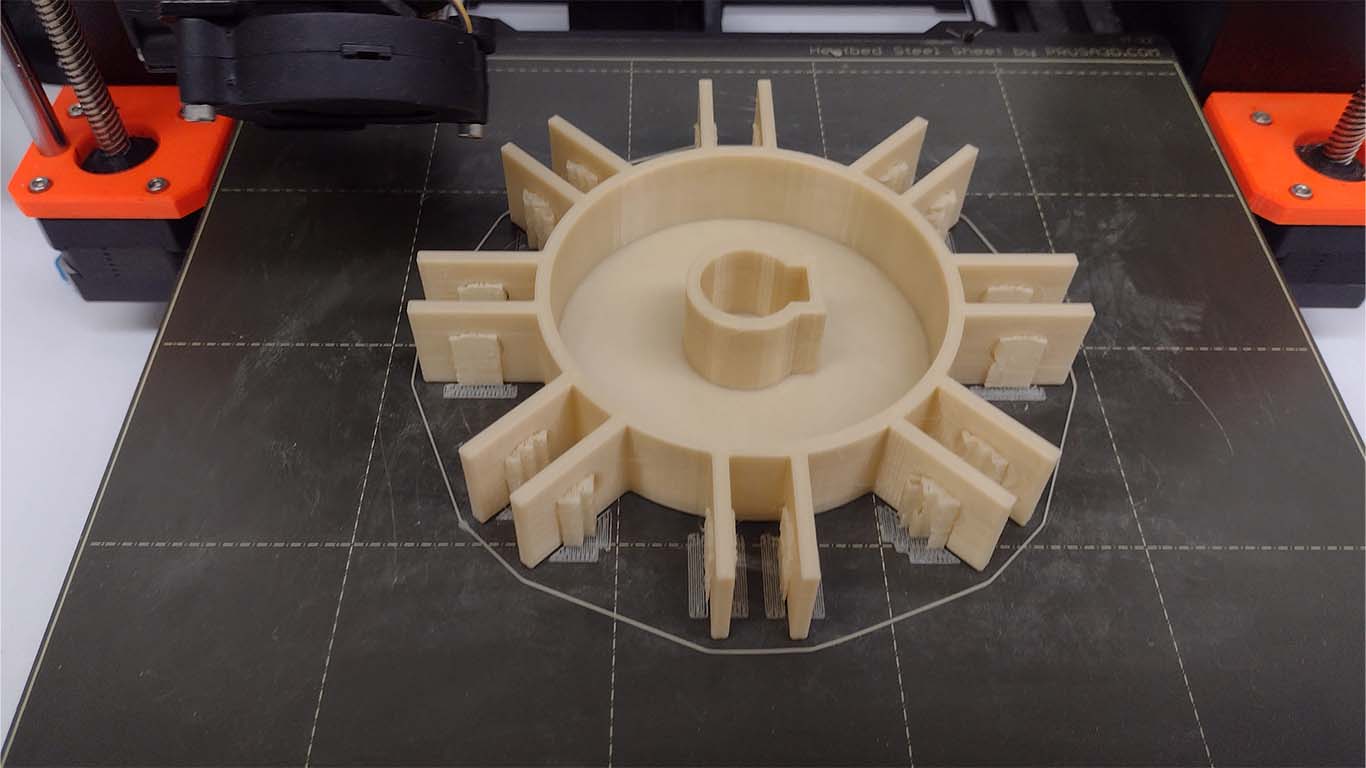
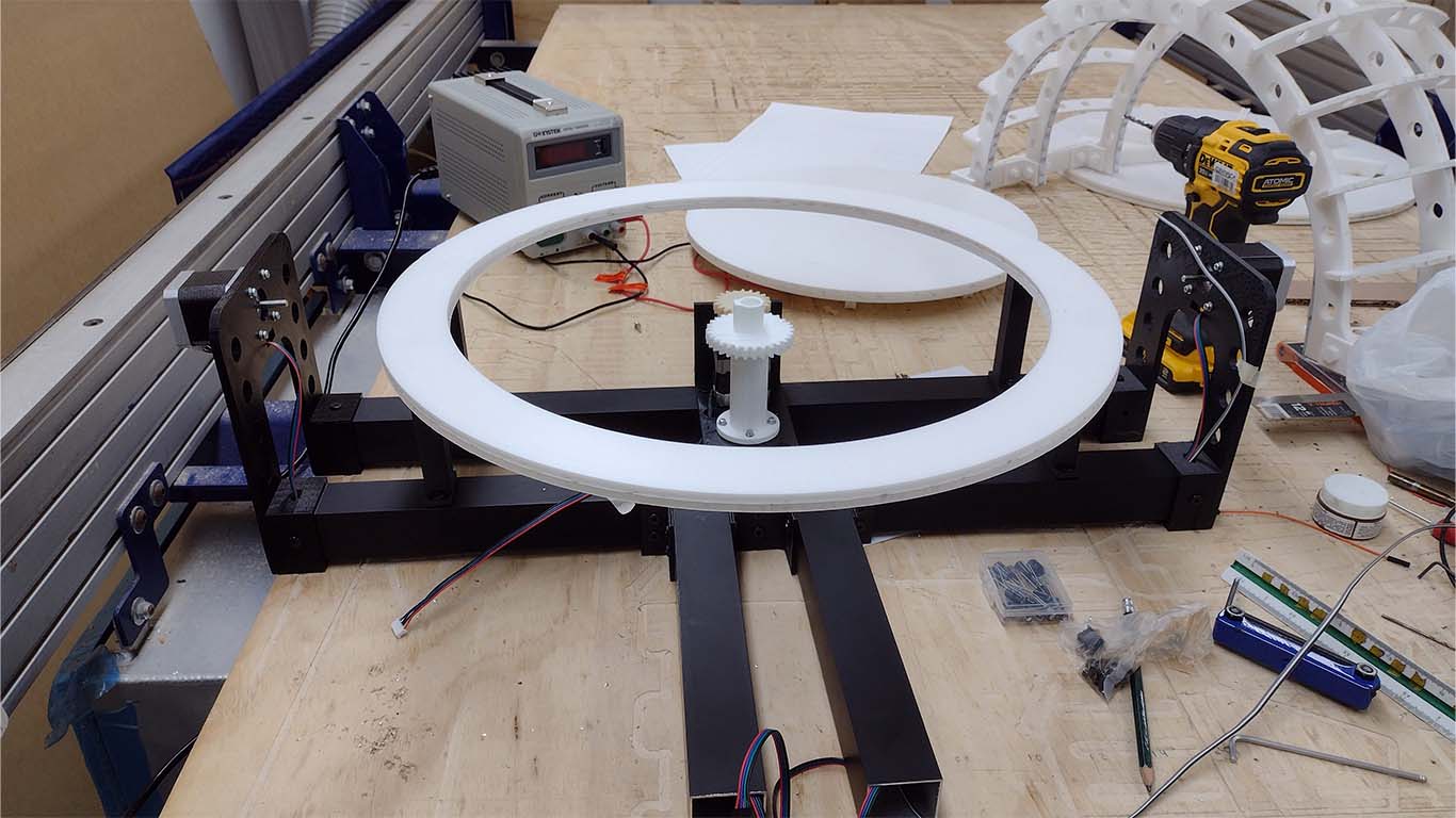
In order to rotate the entire circular base, I was going to need a piece that can support the size of the rotating plate, so I proposed using only a circular element that, using some FOAM strips, can support and at the same time rotate without any inconvenience.
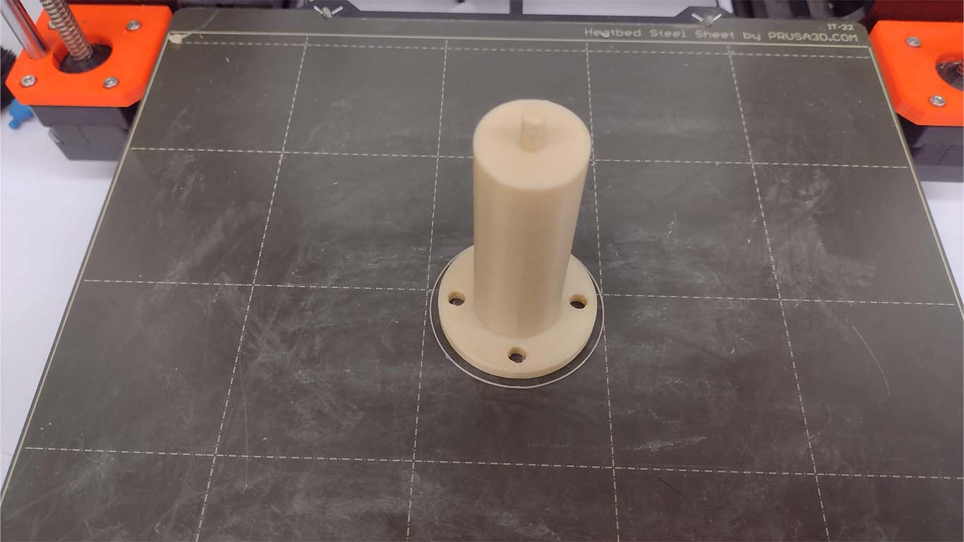
On the other hand, to hold the gears, I had to use another vertical element that would serve as an axis to move them. For the first spiral I thought that only 3D printing would be enough. Here is my proposal for the 2nd spiral that worked individually, but when it came to placing the gear and making it work, it had problems.
Finally, here we can see how the entire base was going to be composed, where we have the 3D printed parts connected to the stepper motor and I also show a test video of how it works.
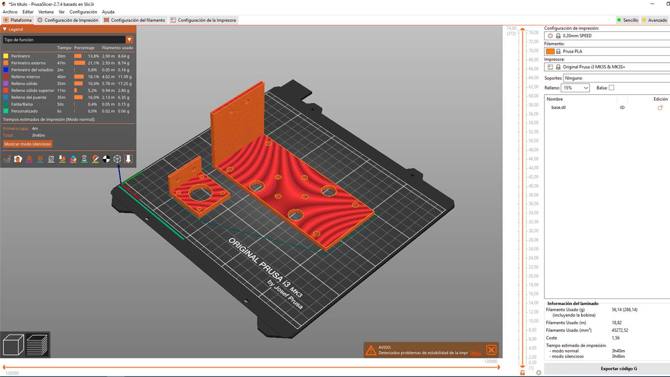
ARTIFACT BASE
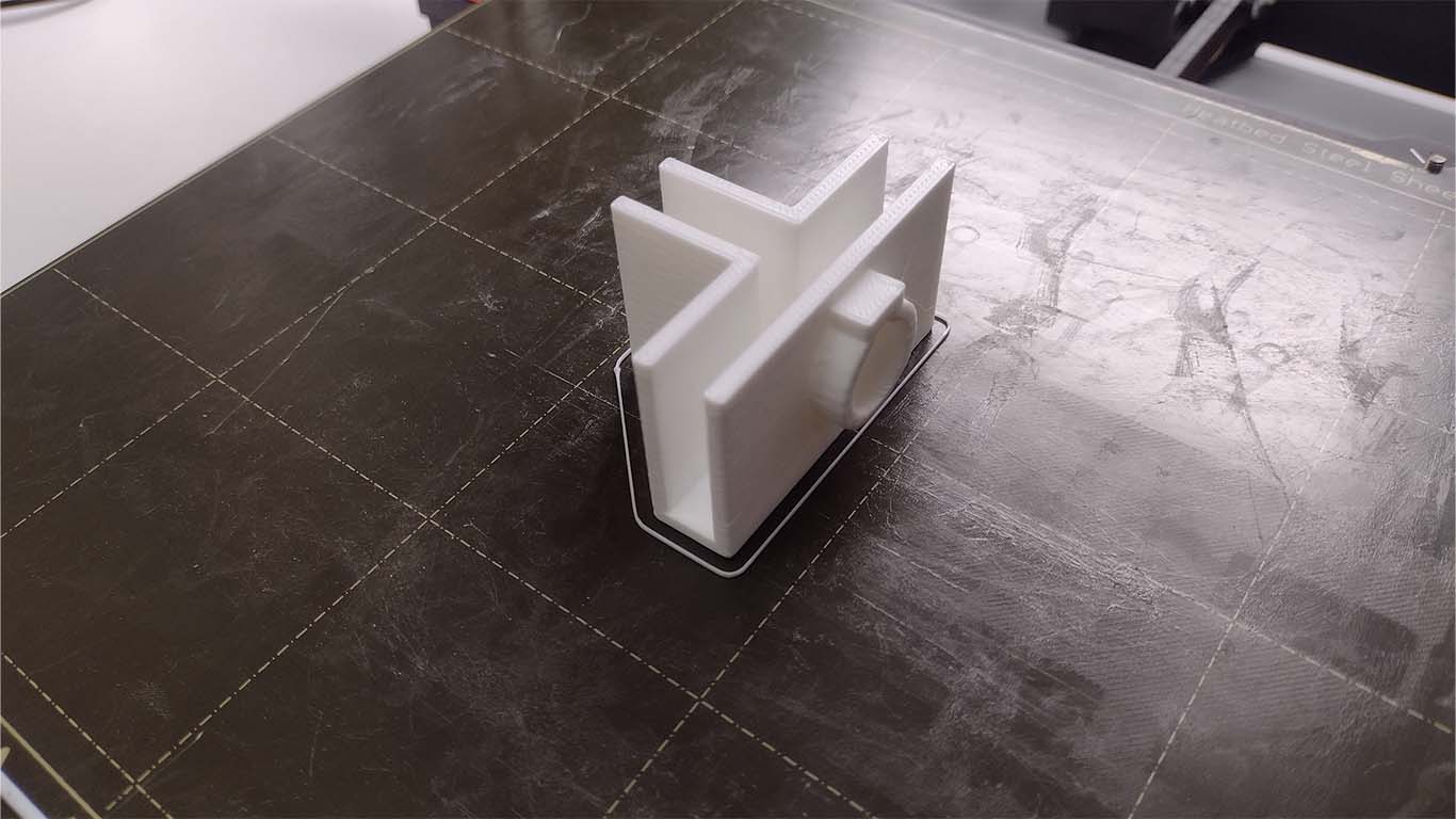
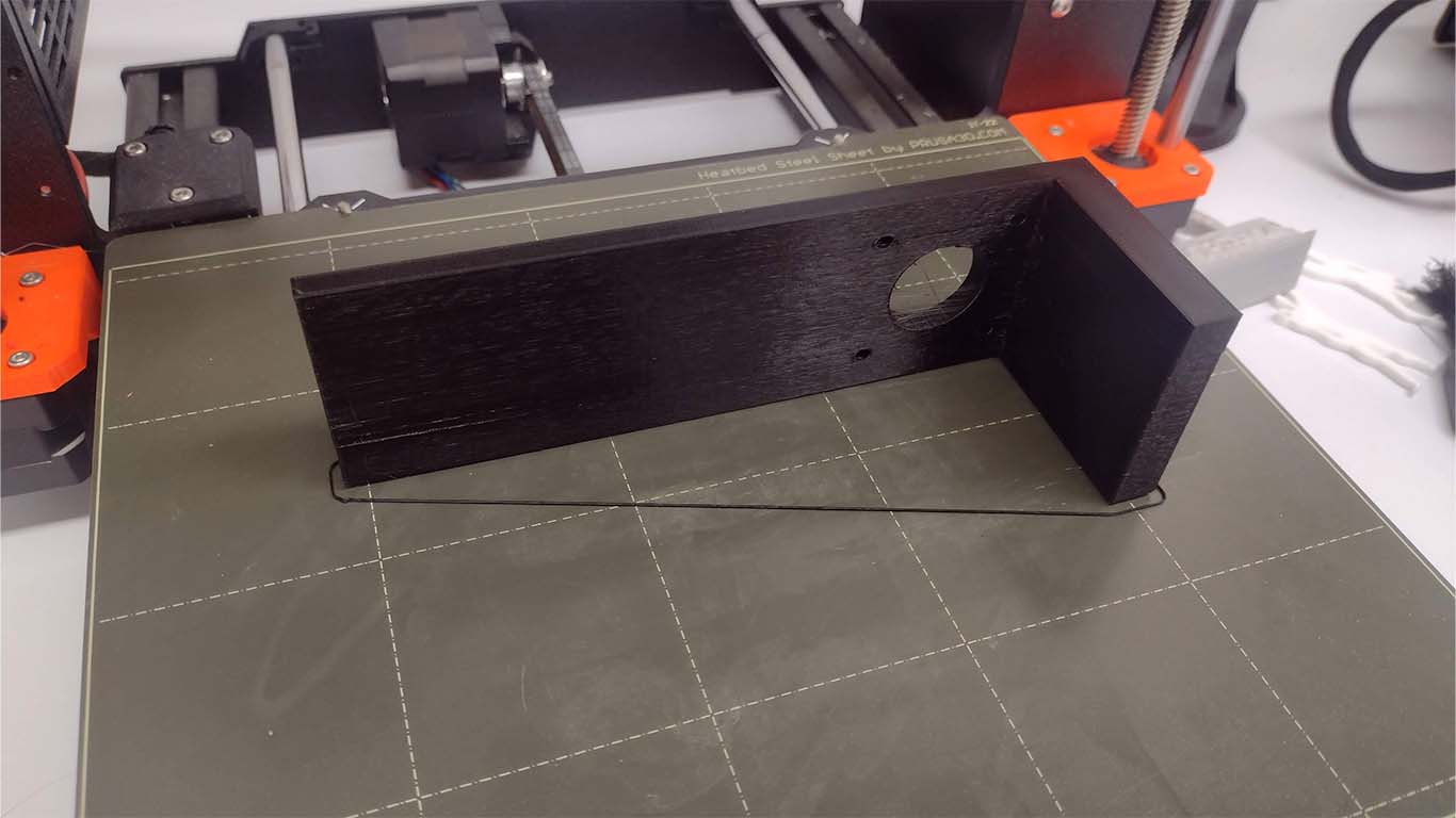
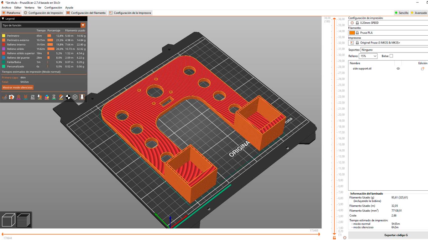
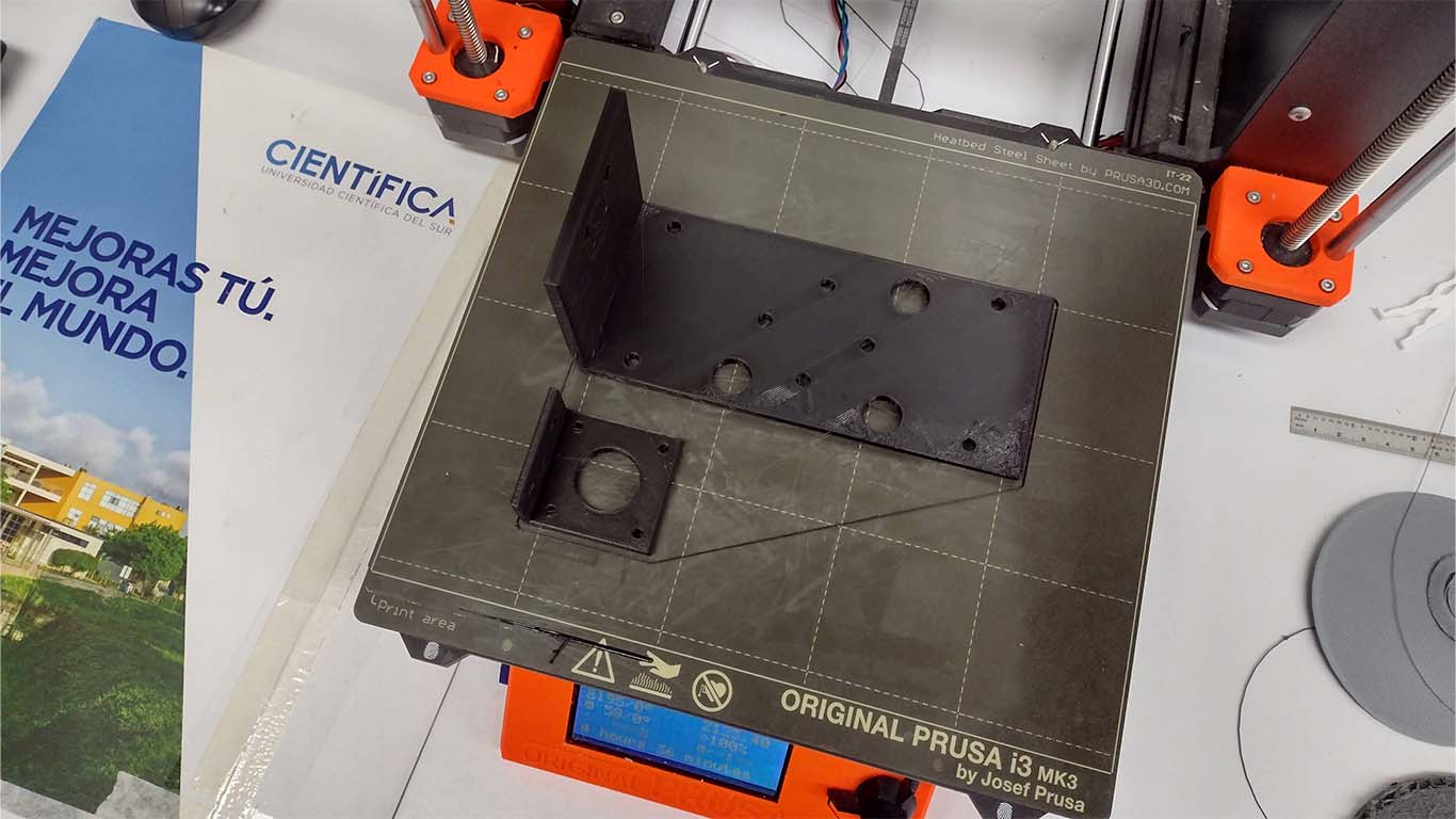
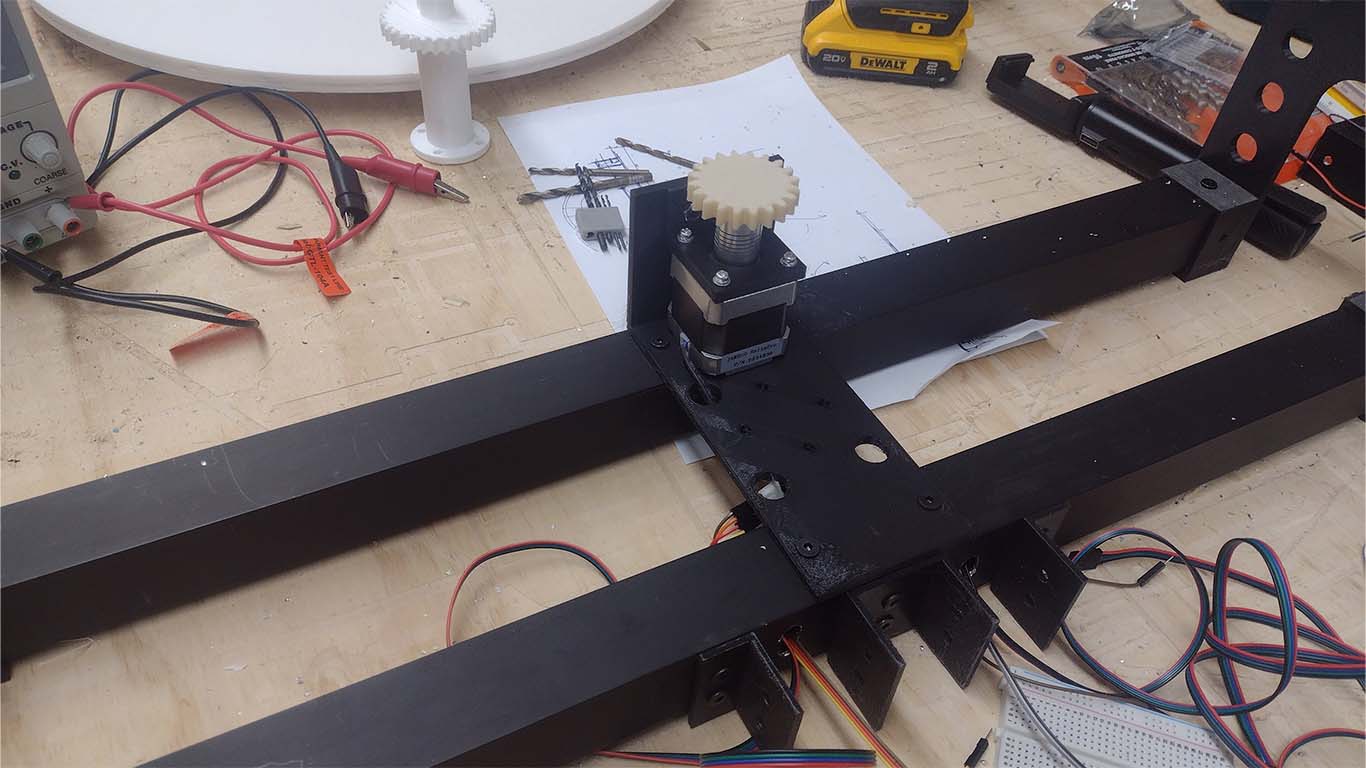
For the base of the artifact, I started by printing the side components of the machine that was going to support the entire structure of the arches, along with the stepper motor. In addition, I wanted to do it in a way that they could be joined with black aluminum to serve as support for the entire artifact. Here is a photograph of the lateral base.
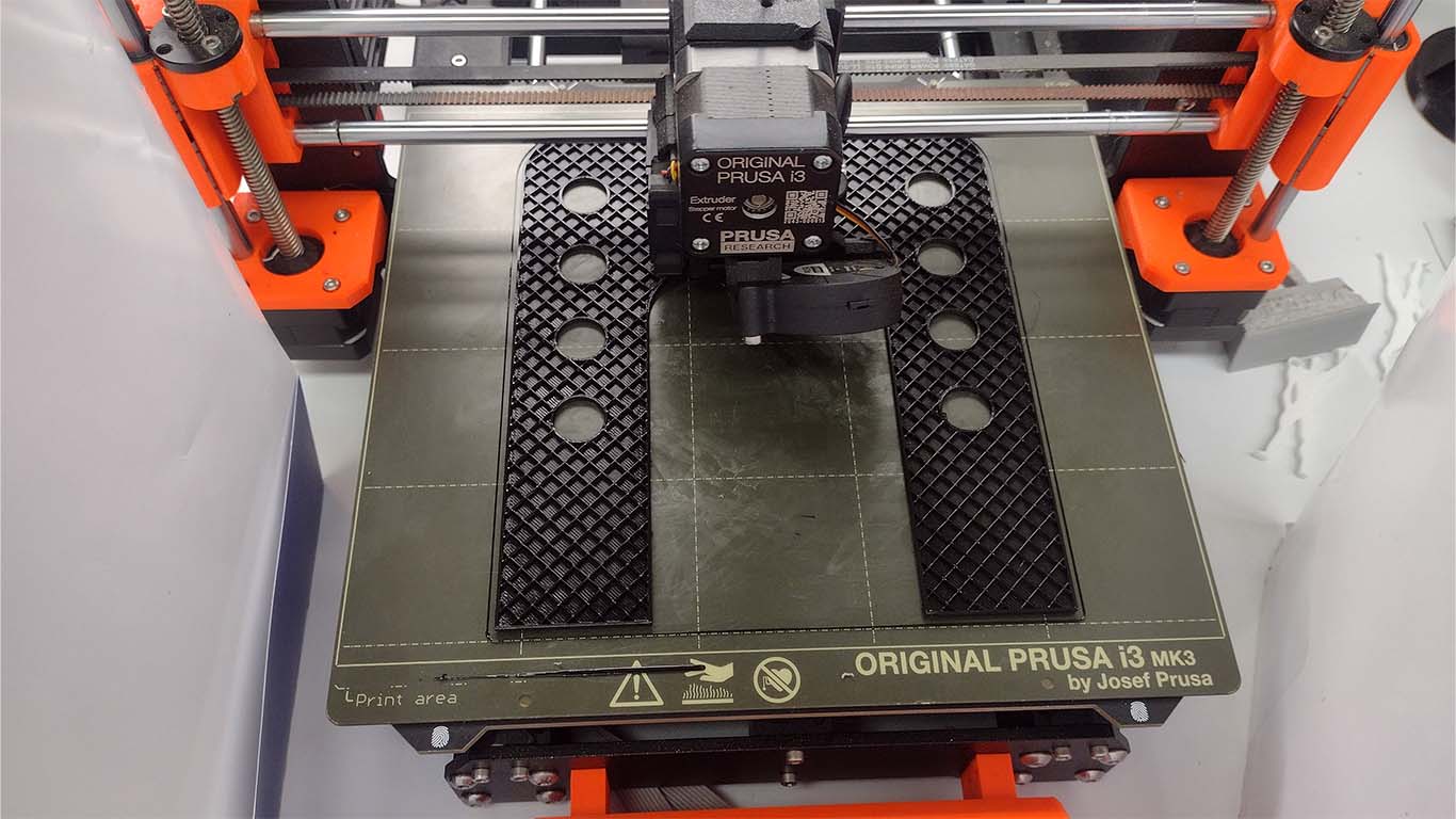
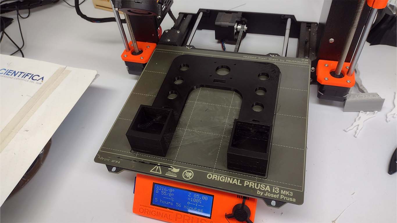
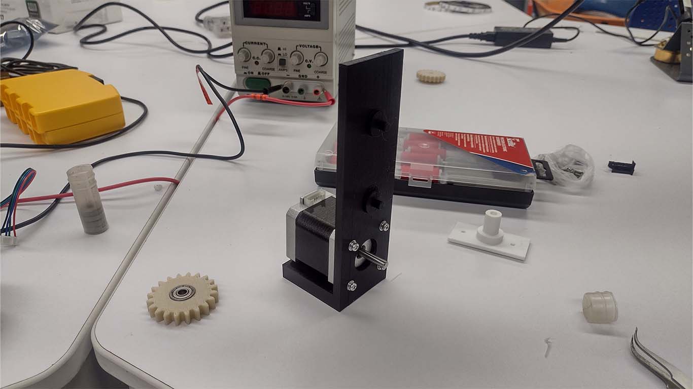
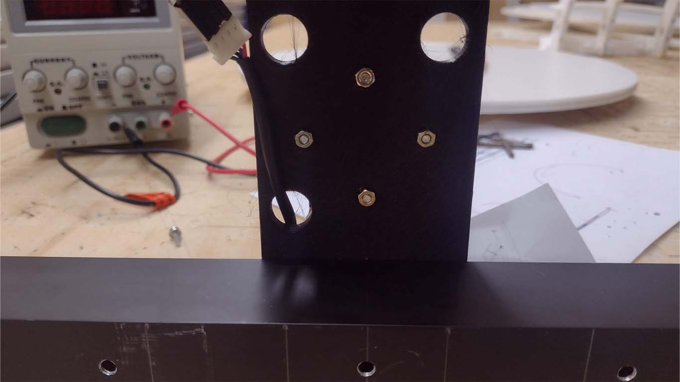
After obtaining both sides printed, I moved on to place the stepper motor where the 3D piece had the exact holes for its adaptation and correct operation.
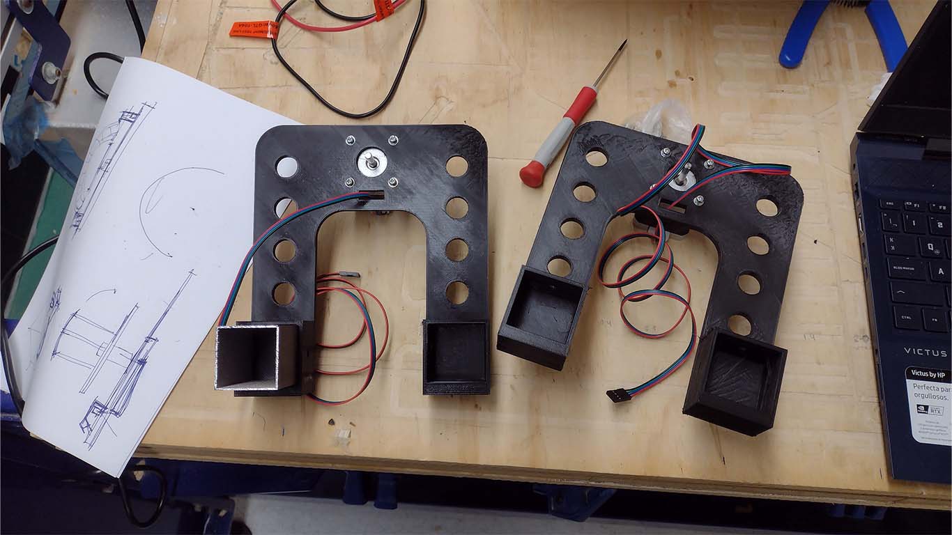
Finally, in the base assembly stage, I was able to connect both printed parts with the black aluminum to be able to have the base assembled and ready for the respective mechanisms and electronics tests. Here is a photograph when I completed the second spiral.
THIRD SPIRAL
The third spiral was developed in week 18 and here I leave the link so you can learn more about what was developed THIRD SPIRAL
FINAL STRUCTURE OF ARCHES
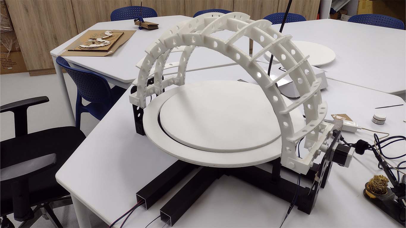
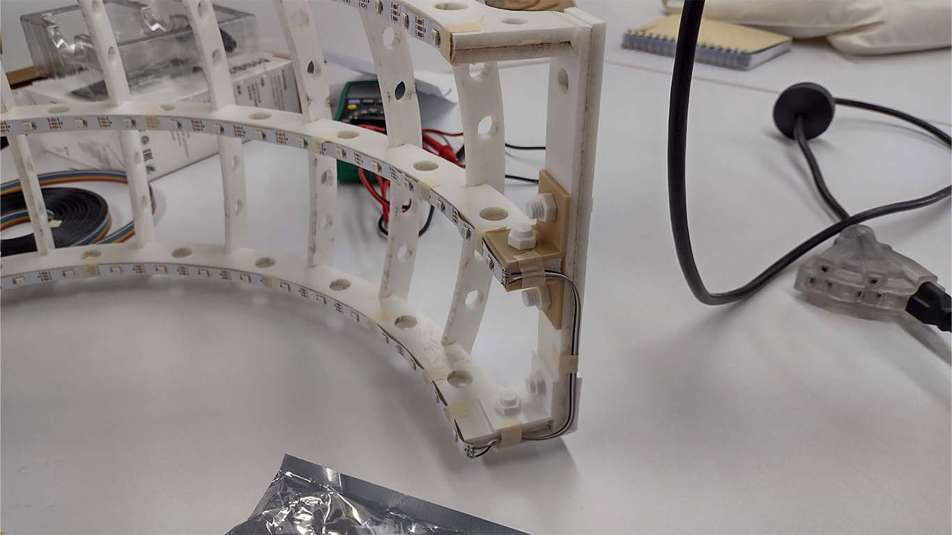
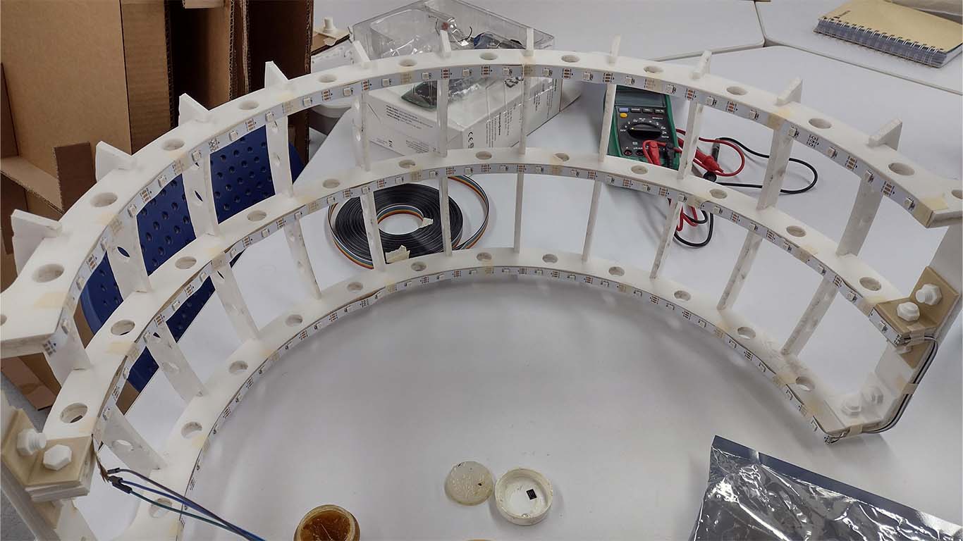
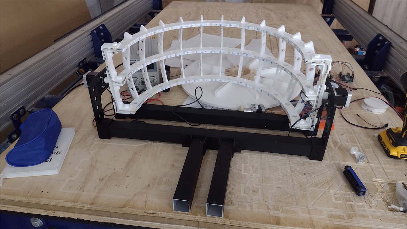
For the final structure of the arches, after laser cutting all the FOAM pieces of the arches, we proceeded to place and secure all the 3D pieces, both bolts, nuts and grip accessories that make up the entire structure of the arches together with the electrical part.
We began to place all the nuts and bolts in the final structure to secure the strips and arches.
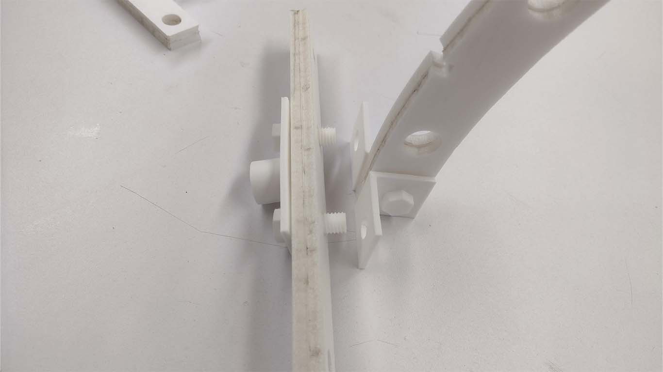
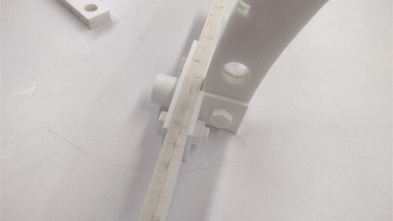
Finally, after placing and adjusting all the bolts and nuts made in 3D, as well as the placement of the neopixels in each arc for the electronics, we can see that everything fits well and is adjusted according to the objective I was looking for.
BASE ASSEMBLY
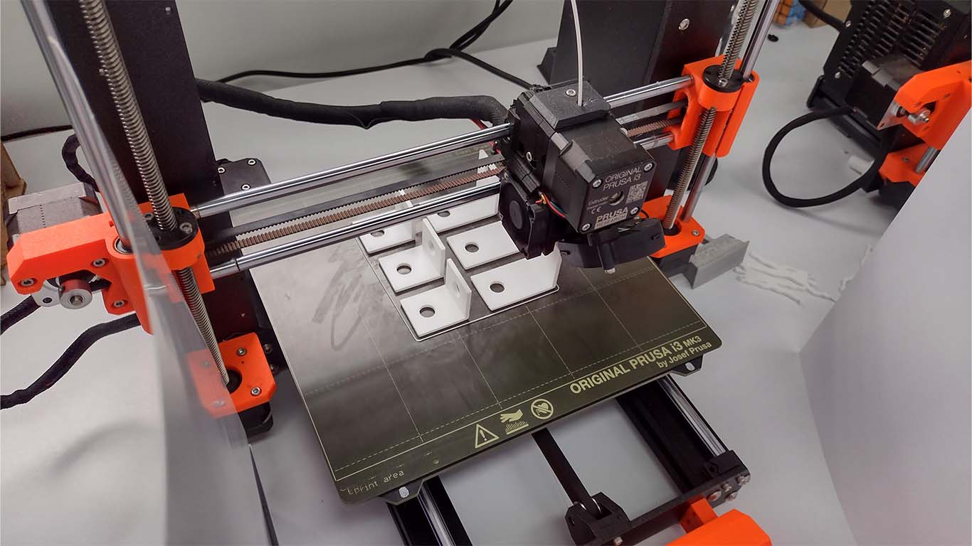
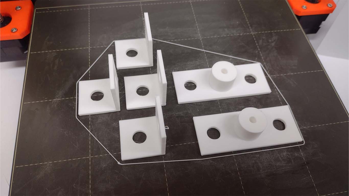
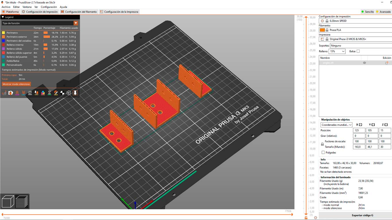
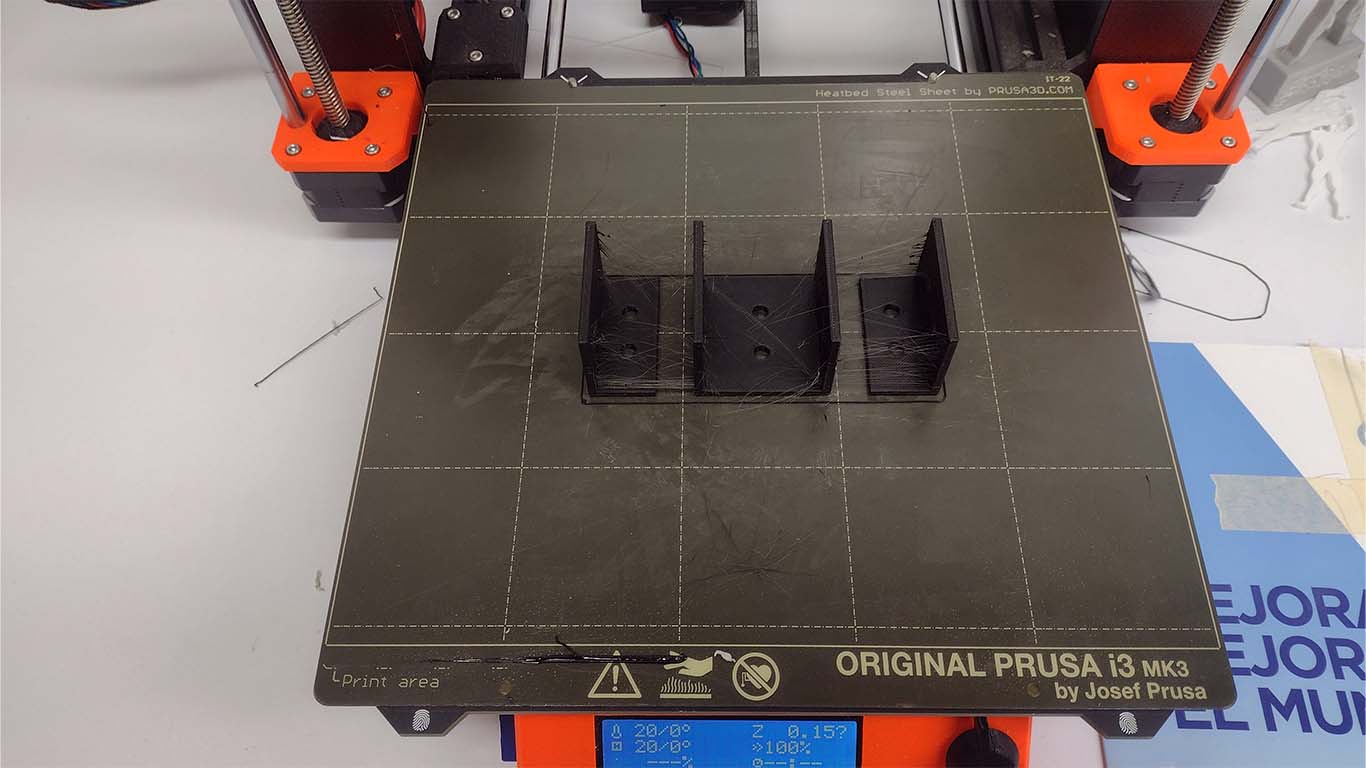
To finish the assembly of the Lightdome base, I had to print, similar to the accessories used in the arches, other accessories for the base in black filament that could help me connect the aluminums, along with other remaining components that needed to be made. Here I first had the angle type accessories printed that were going to join the base with the control part of the device.
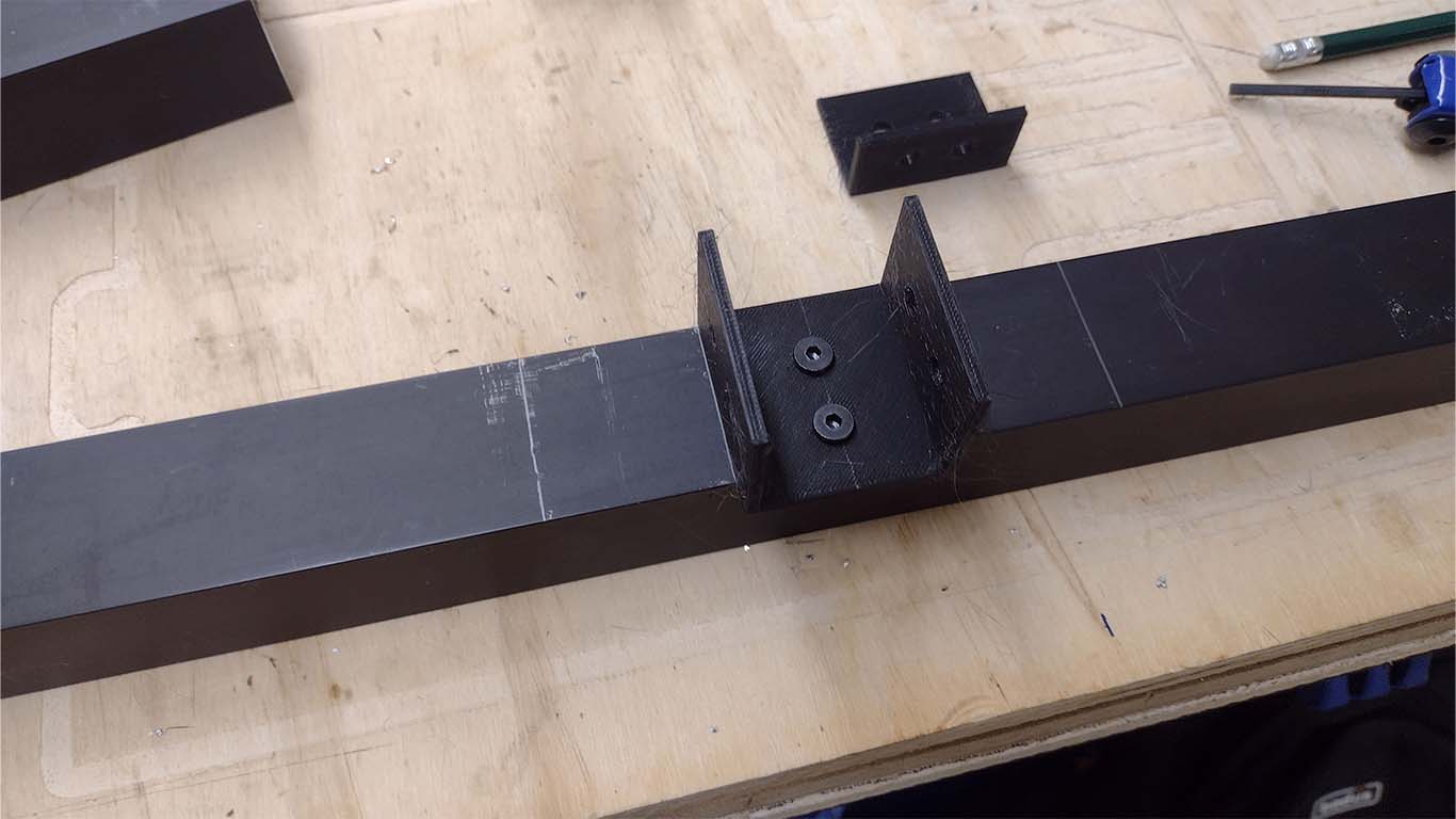
To join and screw the entire base together I used M5 SCREWS which are what was recommended to adjust all the components together with the 3D pieces. Here is a photograph of me adjusting the pieces with the aluminum.
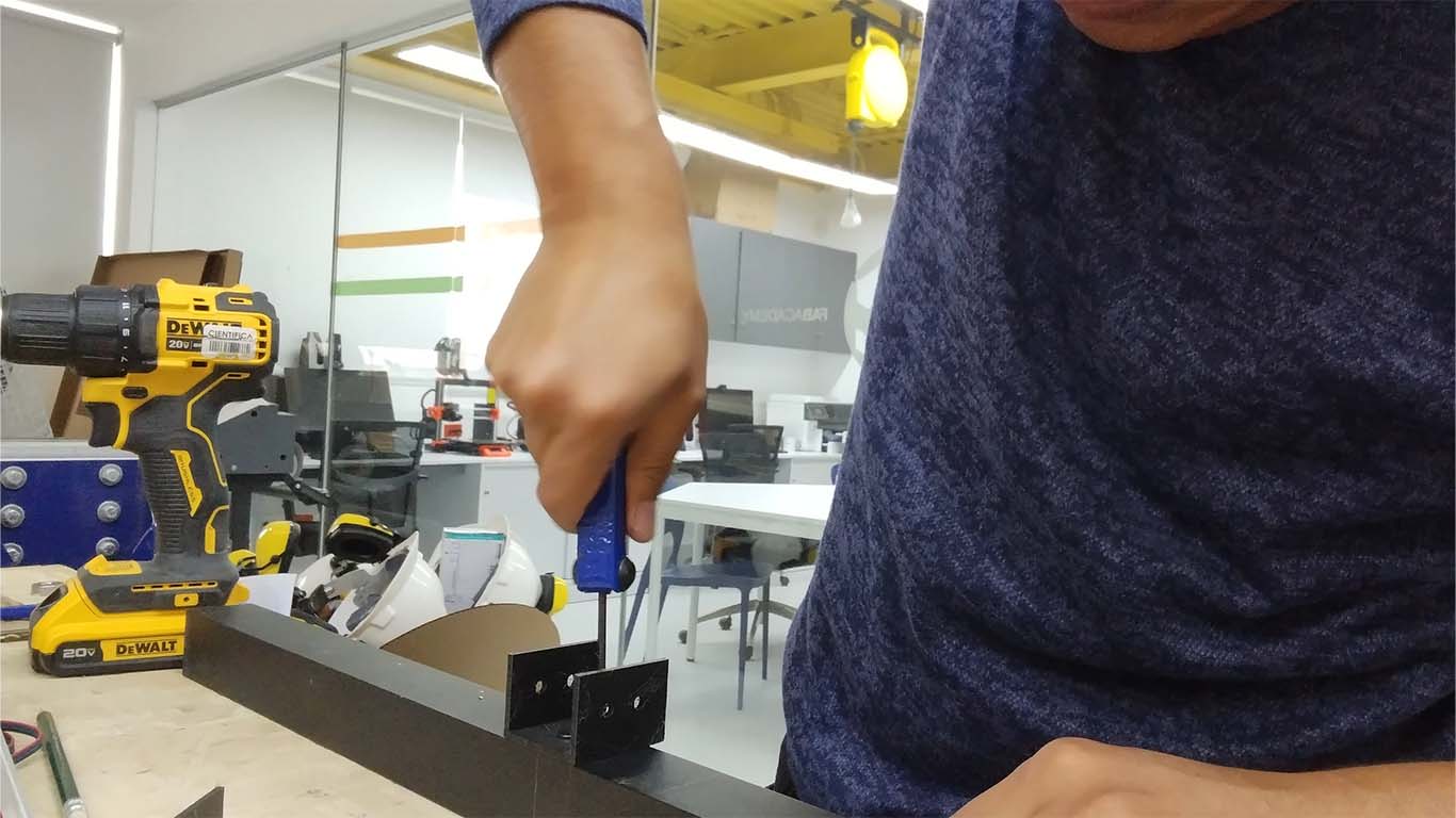
The result was good because the M5 screw and the adjustment did not cause the 3D accessories used to break.
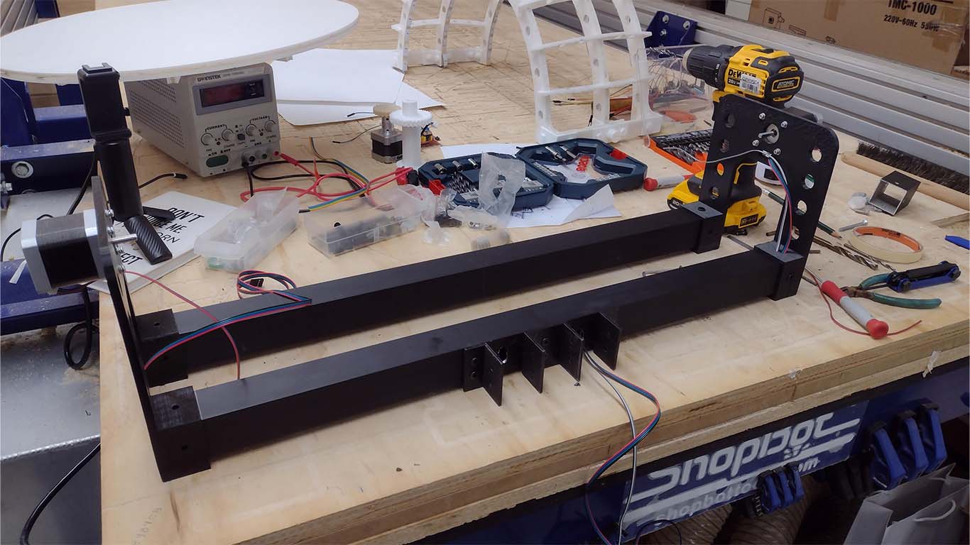
Finally, I was able to place all the accessories that were going to connect with the control part of the machine and I also began to place the connection cables for the stepper motor that were inside the aluminum.
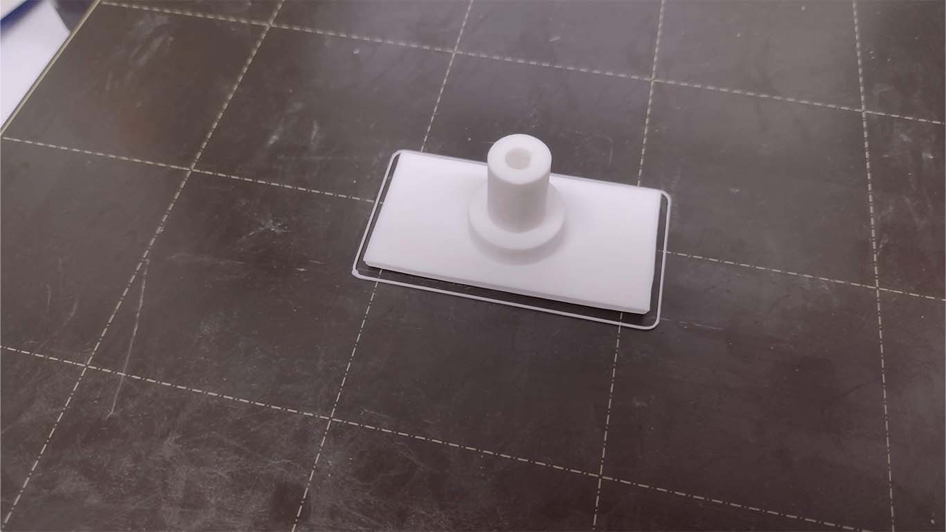
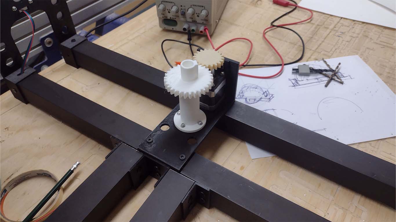
On the other hand, I also started working on the base of the stepper motor and the gear system that will have the rotating circular base. So I had its base printed and also an element that can keep the stepper motor adjusted to avoid too many vibrations.
Then I began to place the components and the entire gear system that were going to support the circular base. Here's a photo when I started placing the stepper motor and gear system on the base.
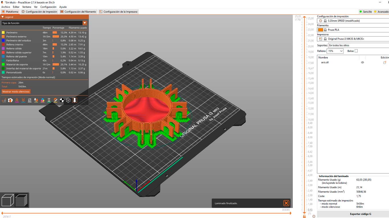
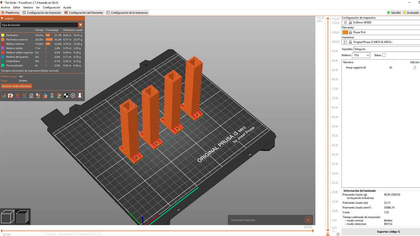
Just when I was putting together the gear system, I got confused about the heights of the gears and had to have it reprinted. Here are some screenshots of the final impressions of gears and shaft for the rotating base.
On the other hand, I realized that 3D printing alone was not going to work because there was a lot of friction and the noise was a lot, that's why I added a bearing so that it can rotate normally.
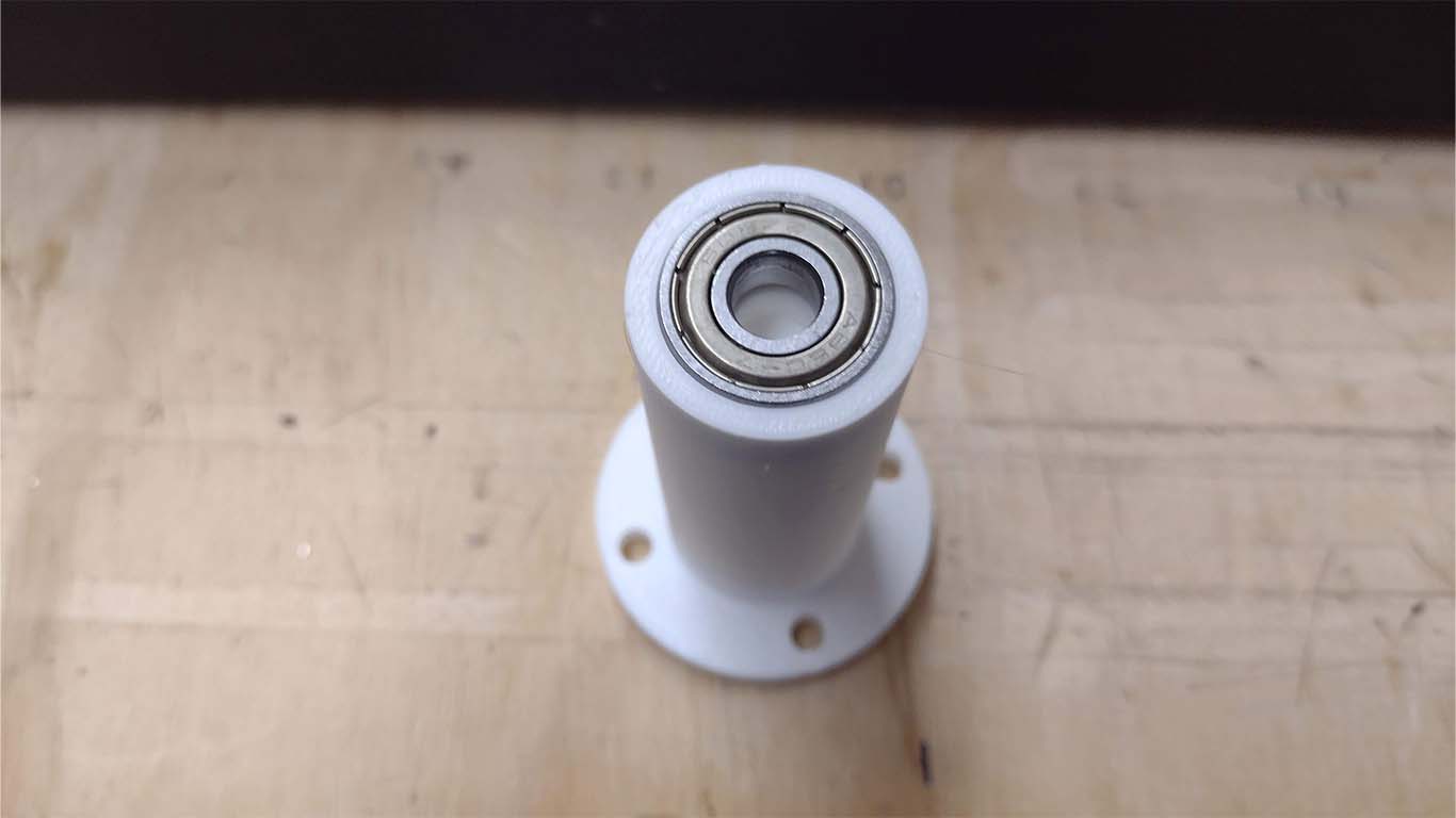
After having the parts ready, I assemble them on the base and connect them to the stepper motor bearing and it would be ready to go.
Finally, after placing all the parts of the gear system, I had the supports printed for the circle where the information of the degrees and the orientation to which the model is directed goes.
After finishing printing all the pieces and being assembled, the structure part would be ready to place only the rotating base and the arch. Now we will move on to the control part.
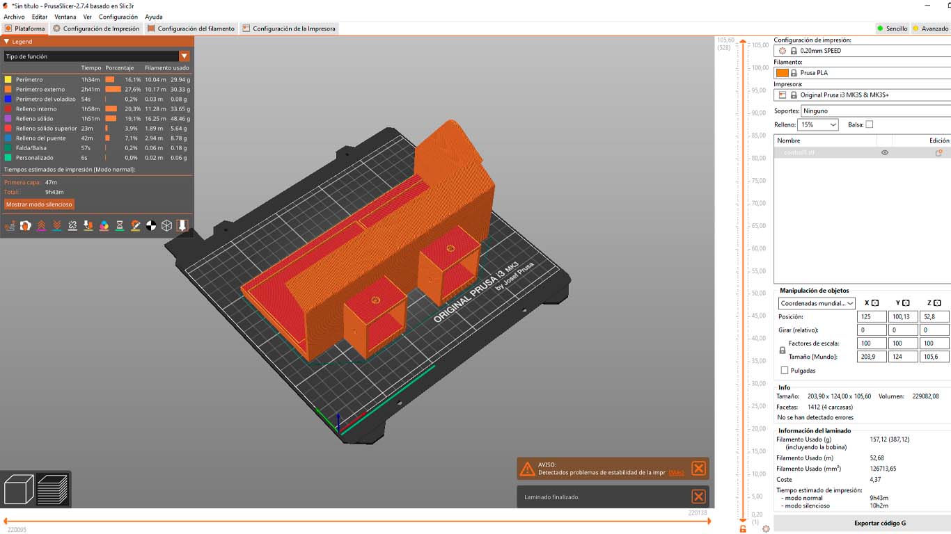
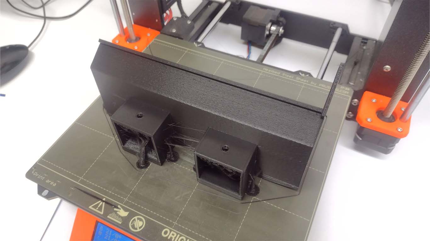
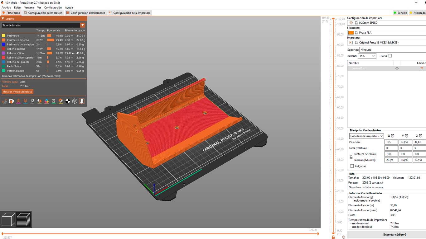
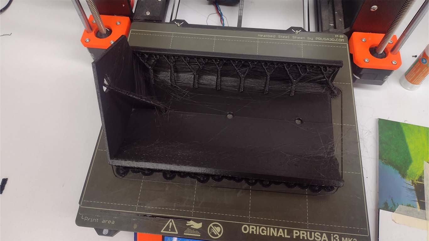
Finally, to finish with the printing parts, I had to send the box where the electronic board and control were going to go. Therefore, first I had the box printed in 2 parts, where the idea was to make a component that is easily disassembled and that is only placed under pressure. Here is a photograph of the first part that will also be connected to the aluminum base of the device.
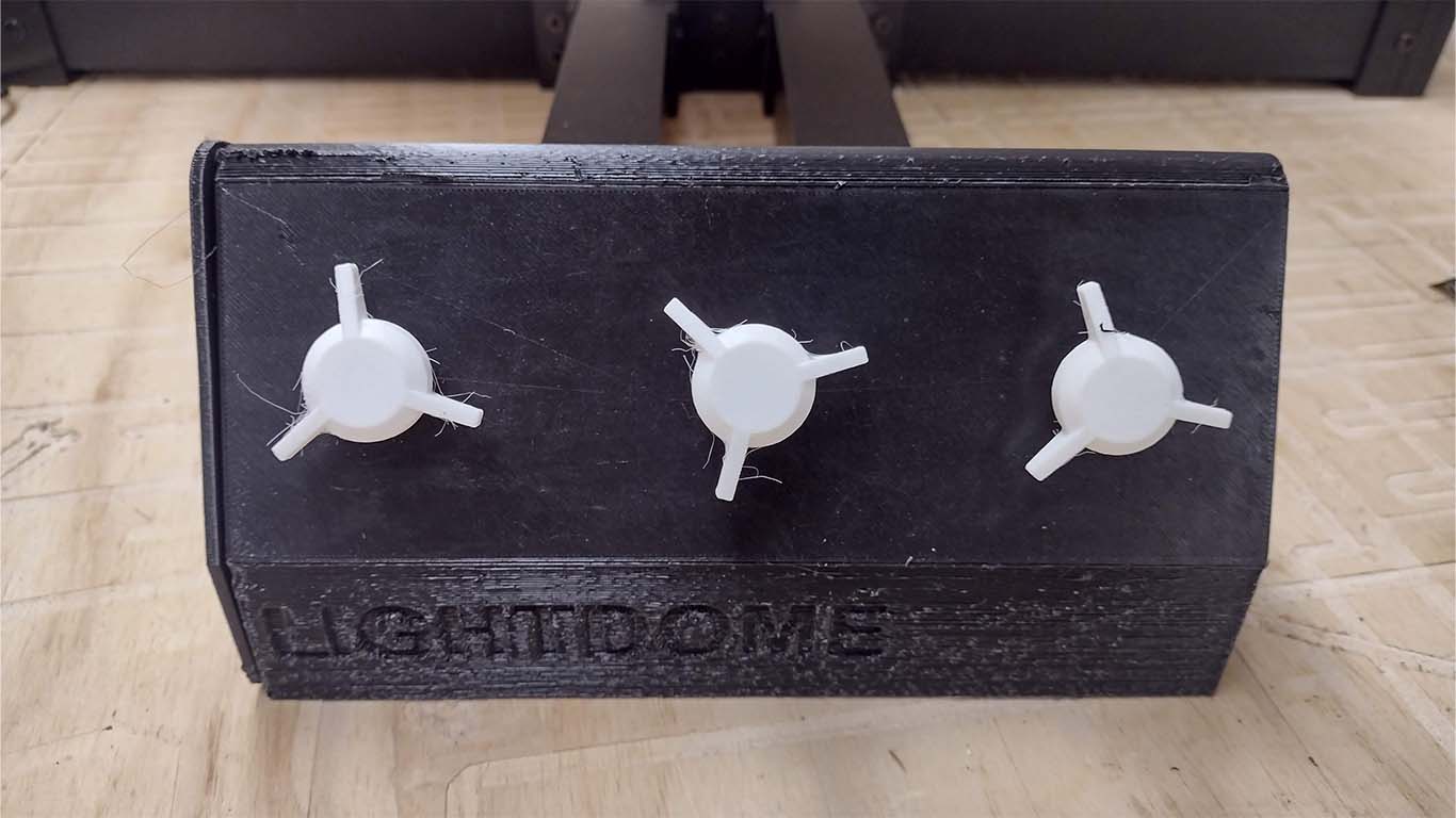
Then I sent the control part where the potentiometers were going to go to control the device.
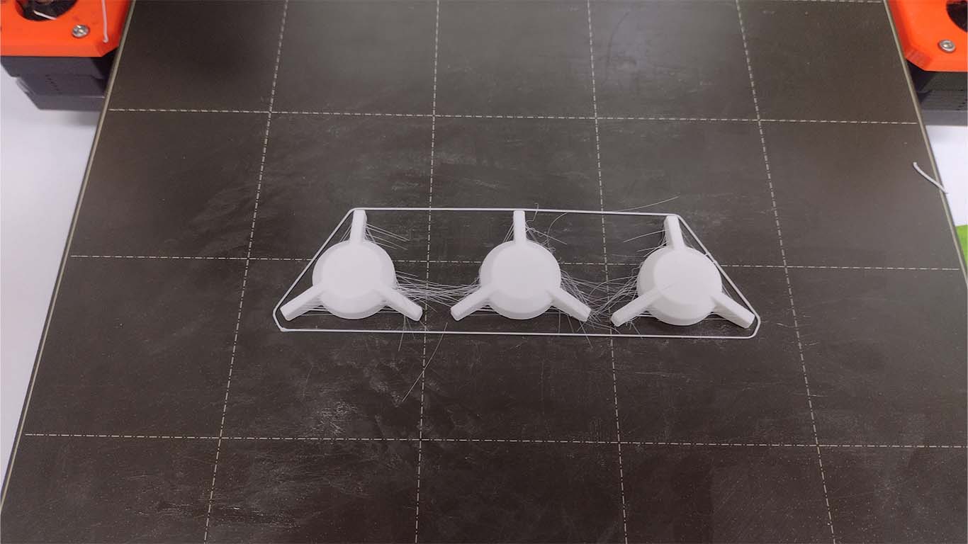
Finally, the 3D printing of the potentiometers was also carried out to be able to have better control of the device, in this case I wanted to use a similar design that the PRUSA MK3 3D printers have and tried to replicate. Here the result.
After being able to print all the parts that 3D printing includes and the evolution that I had in the spiral methodology, it is important to do it to advance the final project and know what works and what doesn't, well here is a photograph of my final delivery where all the pieces were assembled correctly.
ELECTRONIC
FIRST SPIRAL
The first spiral for my project was developed in week 16 since until this week I had not made much progress on the final project, but here is the link if you want to know more SPIRAL ONE
FIRST STEPS WITH STEPPER MOTORS
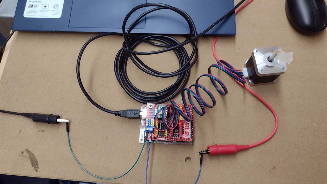
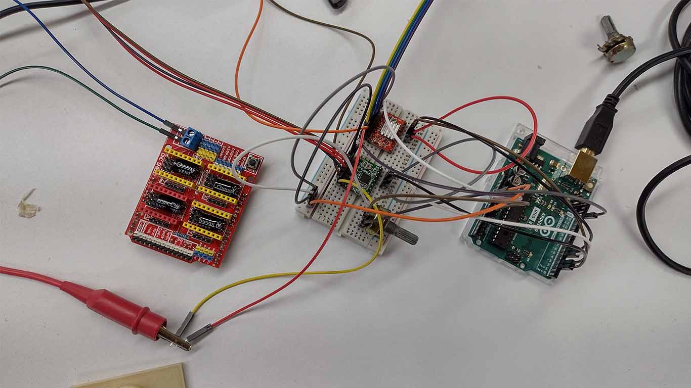
For the first spiral of electronics it was to know and take my first steps in programming stepper motor since they will be the outputs that I am going to use for my final project. The objective was to know the operation, connection and how the stepper motors work since I did not have the opportunity to program them during the outputs devices week. For the first spiral they recommended me to use the ARDUINO UNO R3 + SHIELD ARDUINO CNC V3.
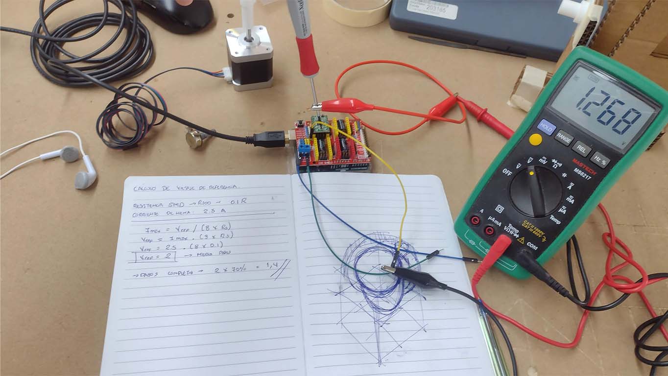
Before carrying out the programming we have to calculate the reference voltage, which is a necessary calculation when using the stepper motor. The calculation is carried out since the technical specifications of the drivers, whether the A4899 or the DRV8825, have to be calculated to provide the necessary voltage to move the stepper motors. In my case, according to the technical specifications of my NEMA17 stepper motor, the voltage was 1.4, however only my drivers reached approximately 1.2, which was the maximum and was the value that I will use for my stepper motor. To understand better you can visit my WEEK 16 page.
After calculating and configuring the drivers in my a4988 case, we can program and see how the stepper motor work correctly.
As you can see in the previous video, first I tried with only one stepper motor using the SHIELD, then I tried with 2 stepper motors connected to the ARDUINO since I thought I was only going to use 2 for my final project and the goal is to synchronize both stepper motors with the SHIELD now. It is easier to program and that is the idea of spirals.
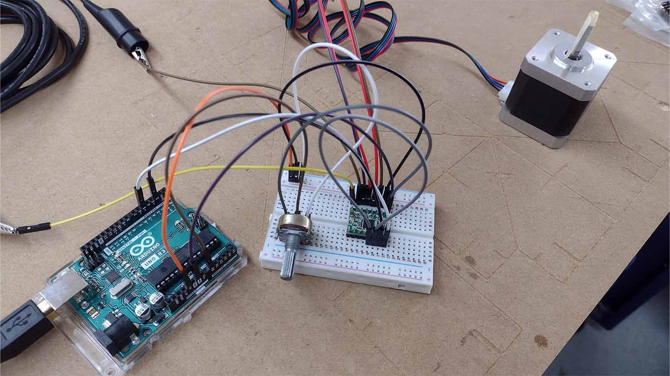
POTENTIOMETER + STEPPER MOTOR
After having done the tests with the ARDUINO SHIELD V3, the second step I wanted to do is to use a potentiometer but without the shield and be able to use the PROTOBOARD to make the connection faster and know the connection pins. Here is a screenshot of all the connections.
Here I leave the programming code that helped me program without the shield component.
                                    // defines pins
                                    #define stepPin 2
                                    #define dirPin 5

                                    const int stepsPerRevolution = 200; // Number of steps per revolution (adjust according to your motor)
                                    const float degreesPerStep = 360.0 / stepsPerRevolution; // Degrees per step

                                    int currentStep = 0; // Current motor position in steps
                                    int targetStep = 0;  // Target motor position in steps

                                    void setup() {
                                    // Sets the two pins as Outputs
                                    pinMode(stepPin, OUTPUT);
                                    pinMode(dirPin, OUTPUT);
                                    Serial.begin(9600); // For debugging
                                    }

                                    void loop() {
                                    // Read the potentiometer value
                                    int potValue = analogRead(A0);

                                    // Map the potentiometer value to an angle between 0 and 180 degrees
                                    int targetAngle = map(potValue, 0, 1023, 0, 180);

                                    // Calculate the target step position
                                    targetStep = targetAngle / degreesPerStep;

                                    // Ensure the targetStep is within bounds (0 to 180 degrees)
                                    targetStep = constrain(targetStep, 0, 180 / degreesPerStep);

                                    // Move the motor to the target position
                                    moveToPosition(targetStep);

                                    // Print debug information
                                    Serial.print("Potentiometer Value: ");
                                    Serial.print(potValue);
                                    Serial.print(" | Target Angle: ");
                                    Serial.print(targetAngle);
                                    Serial.print(" | Current Step: ");
                                    Serial.print(currentStep);
                                    Serial.print(" | Target Step: ");
                                    Serial.println(targetStep);
                                    }

                                    void moveToPosition(int targetStep) {
                                    if (targetStep > currentStep) {
                                        // Move forward
                                        digitalWrite(dirPin, HIGH);
                                        while (currentStep < targetStep) {
                                        digitalWrite(stepPin, HIGH);
                                        delayMicroseconds(1000); // Adjust delay according to desired speed
                                        digitalWrite(stepPin, LOW);
                                        delayMicroseconds(1000); // Adjust delay according to desired speed
                                        currentStep++;
                                        }
                                    } else if (targetStep < currentStep) {
                                        // Move backward
                                        digitalWrite(dirPin, LOW);
                                        while (currentStep > targetStep) {
                                        digitalWrite(stepPin, HIGH);
                                        delayMicroseconds(1000); // Adjust delay according to desired speed
                                        digitalWrite(stepPin, LOW);
                                        delayMicroseconds(1000); // Adjust delay according to desired speed
                                        currentStep--;
                                        }
                                    }
                                    }
After programming and seeing that the programming for the stepper motor works, I started using it in the cardboard model that I made for my first spiral. Here is a test video and result of my first spiral.
SECOND SPIRAL
Regarding the second spiral, it was developed during week 17, here is the link to the progress SECOND SPIRAL
POTENTIOMETER + 2 STEPPER MOTOR
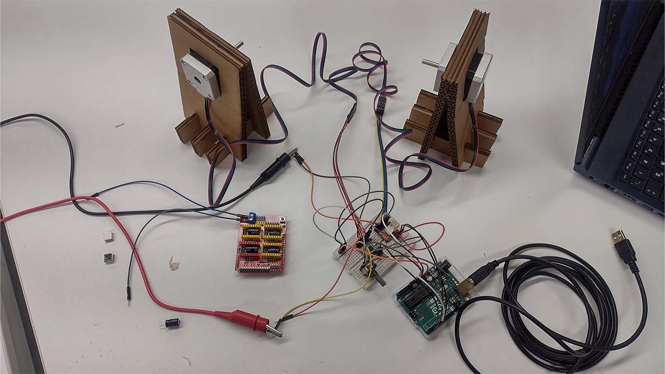
After the first experience in programming the stepper motors and closing some doubts I had about their operation. For the second spiral I decided to use 2 stepper motors due to the weight of the arches since a single stepper motor was not going to be enough, so to continue advancing and closing spirals, I decided to use 2 stepper motors and I am going to keep the protoboard since the idea is to move forward and close each spiral that I generate to achieve the objective.
Here I leave the programming code that I used to be able to move 2 stepper motors with a potentiometer.
                                // defines pins for Motor 1
                                #define stepPin1 2
                                #define dirPin1 5

                                // defines pins for Motor 2
                                #define stepPin2 3
                                #define dirPin2 6

                                const int stepsPerRevolution = 200; // Number of steps per revolution (adjust according to your motor)
                                const float degreesPerStep = 360.0 / stepsPerRevolution; // Degrees per step

                                int currentStep1 = 0; // Current position of Motor 1 in steps
                                int currentStep2 = 0; // Current position of Motor 2 in steps

                                void setup() {
                                  // Sets the two pins as Outputs for Motor 1
                                  pinMode(stepPin1, OUTPUT);
                                  pinMode(dirPin1, OUTPUT);

                                  // Sets the two pins as Outputs for Motor 2
                                  pinMode(stepPin2, OUTPUT);
                                  pinMode(dirPin2, OUTPUT);

                                  Serial.begin(9600); // For debugging
                                }

                                void loop() {
                                  // Read the potentiometer value
                                  int potValue = analogRead(A0);

                                  // Map the potentiometer value to an angle between 0 and 180 degrees
                                  int targetAngle = map(potValue, 0, 1023, 0, 180);

                                  // Calculate the target step position
                                  int targetStep = targetAngle / degreesPerStep;

                                  // Ensure the targetStep is within bounds (0 to 180 degrees)
                                  targetStep = constrain(targetStep, 0, 180 / degreesPerStep);

                                  // Move both motors to the target position
                                  moveToPosition(targetStep);

                                  // Print debug information
                                  Serial.print("Potentiometer Value: ");
                                  Serial.print(potValue);
                                  Serial.print(" | Target Angle: ");
                                  Serial.print(targetAngle);
                                  Serial.print(" | Current Step 1: ");
                                  Serial.print(currentStep1);
                                  Serial.print(" | Current Step 2: ");
                                  Serial.print(currentStep2);
                                  Serial.print(" | Target Step: ");
                                  Serial.println(targetStep);
                                }

                                void moveToPosition(int targetStep) {
                                  moveMotor(stepPin1, dirPin1, currentStep1, targetStep);
                                  moveMotor(stepPin2, dirPin2, currentStep2, targetStep);
                                }

                                void moveMotor(int stepPin, int dirPin, int ¤tStep, int targetStep) {
                                  if (targetStep > currentStep) {
                                    // Move forward
                                    digitalWrite(dirPin, HIGH);
                                    while (currentStep < targetStep) {
                                      digitalWrite(stepPin, HIGH);
                                      delayMicroseconds(1000); // Adjust delay according to desired speed
                                      digitalWrite(stepPin, LOW);
                                      delayMicroseconds(1000); // Adjust delay according to desired speed
                                      currentStep++;
                                    }
                                  } else if (targetStep < currentStep) {
                                    // Move backward
                                    digitalWrite(dirPin, LOW);
                                    while (currentStep > targetStep) {
                                      digitalWrite(stepPin, HIGH);
                                      delayMicroseconds(1000); // Adjust delay according to desired speed
                                      digitalWrite(stepPin, LOW);
                                      delayMicroseconds(1000); // Adjust delay according to desired speed
                                      currentStep--;
                                    }
                                  }
                                }
In the following video we can see how the programming works and the potentiometer moves the stepper motors when a movement is made.
After having the programming ready, I place them in the model that I made to know how it works and we can see that the stepper motors have no problem moving the arches and the structure.
MATERIALS AND WEIGHT TEST
During the development of the second spiral I had some problems since I thought that for the final project I could not use cardboard or another type of light material and it had to be made of wood. So when it came to changing the material of the arches, which I had originally thought would be made of wood, because I had problems with the low torque, the stepper motors had to move my entire arch structure. I was worried if it weren't for the teacher ADRIAN TORRES , who mentioned to me that normally I could use cardboard or another material, it was not mandatory to only use wood.
Reading your recommendation gave me relief and I continued working, I still leave you the video of my test using 11mm MDF board where we see that just one arch was a lot of weight, imagine 3 plus the transversal ones, it was going to be impossible for my stepper motors.
On the other hand, I also thought of reducing the design to a single arc, which was the solistical, where the stepper motors were more than enough to move the entire arc, however I wanted to develop the 3 arcs that signify the solstices and the equinoxes to be able to have A more accurate analysis and it could be cardboard or another type of material.
Finally, after carrying out the other processes in parallel such as the arches in FOAM material, I could see that the 2 stepper motors were enough to move the total structure of my arches since they were light and with this I could conclude that I had to use CARDBOARD or FOAM For my project, in the end I chose foam since it has a better finish and is lighter due to its composition.
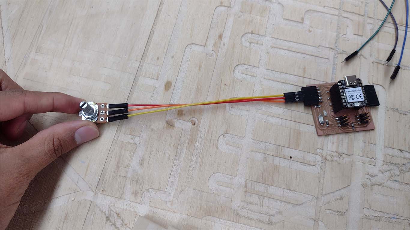
POTENTIOMETER + NEOPIXELS
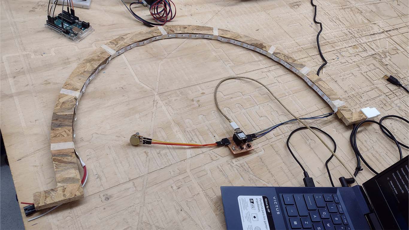
On the other hand, for the second spiral I also began to develop the programming of the neopixels that I was going to use as a simulation of the incidence of the sun. First I started to program it 100% on, everything in an arc, the idea was to see how many neopixels I was going to have in the arcs and see the connection and its programming.
For my first programming it was to see if all the neopixels were working correctly. Here is a photograph of all the neopixels turned on.
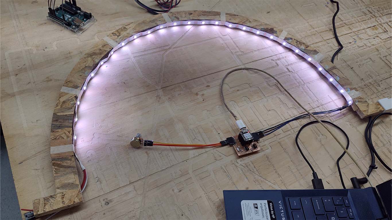
The first mini spiral to start programming my neopixels was to configure it with the potentiometer and have it turn off one by one while turning the potentiometer. Here is a video of the test and everything is correct.
For the second mini spiral I wanted to ensure that every time I move the potentiometer, one neopixel turns on and the previous one turns off. The intention was to achieve the best configuration to simulate solar incidence and with a single neopixel it is very little to achieve the objective, but here is the code and the result.
Here I leave the programming code used, don't forget use "< , >" on the library
                                #include Adafruit_NeoPixel.h

                                    // Neopixel strip configuration
                                    #define NUM_PIXELS 27  // Number of LEDs in the strip
                                    #define PIXEL_PIN 3    // Pin where the Neopixel strip is connected

                                    // Potentiometer configuration
                                    #define POTENTIOMETER_PIN 26  // Analog pin where the potentiometer is connected

                                    // Create Neopixel object
                                    Adafruit_NeoPixel pixels(NUM_PIXELS, PIXEL_PIN, NEO_GRB + NEO_KHZ800);

                                    void setup() {
                                      // Initialize the Neopixel object
                                      pixels.begin();
                                      pixels.show(); // Initialize all LEDs off
                                    }

                                    void loop() {
                                      // Read the potentiometer position
                                      int potValue = analogRead(POTENTIOMETER_PIN);

                                      // Map the potentiometer value to the range of 0 to NUM_PIXELS - 1
                                      int ledIndex = map(potValue, 0, 1023, 0, NUM_PIXELS - 1);

                                      // Turn off all LEDs
                                      for (int i = 0; i < NUM_PIXELS; i++) {
                                        pixels.setPixelColor(i, pixels.Color(0, 0, 0));  // Turn off LED
                                      }

                                      // Turn on only the corresponding LED
                                      pixels.setPixelColor(ledIndex, pixels.Color(255, 255, 255));  // White color

                                      // Update the LED strip
                                      pixels.show();

                                      // Small pause to avoid reading too frequently
                                      delay(100);
                                    }
Finally, for the third mini spiral I wanted to do a group programming of 3 neopixels, where depending on the location of the potentiometer the neopixels are turned on as a group of 3 neopixels. The objective was to increase the lighting in the models and with 3 neopixels it is recommended.
Here I leave the programming code used for the following configuration and it will be used for the final project
                                #include Adafruit_NeoPixel.h

                                    // Neopixel strip configuration
                                    #define NUM_PIXELS 74  // Number of LEDs in the strip
                                    #define PIXEL_PIN 3    // Pin where the Neopixel strip is connected

                                    // Potentiometer configuration
                                    #define POTENTIOMETER_PIN 26  // Analog pin where the potentiometer is connected

                                    // Create Neopixel object
                                    Adafruit_NeoPixel pixels(NUM_PIXELS, PIXEL_PIN, NEO_GRB + NEO_KHZ800);

                                    void setup() {
                                      // Initialize the Neopixel object
                                      pixels.begin();
                                      pixels.show(); // Initialize all LEDs off
                                    }

                                    void loop() {
                                      // Read the potentiometer position
                                      int potValue = analogRead(POTENTIOMETER_PIN);

                                      // Map the potentiometer value to the range of 0 to NUM_PIXELS / 3 - 1
                                      int ledGroup = map(potValue, 0, 1023, 0, NUM_PIXELS / 3 - 1);

                                      // Turn off all LEDs
                                      for (int i = 0; i < NUM_PIXELS; i++) {
                                        pixels.setPixelColor(i, pixels.Color(0, 0, 0));  // Turn off LED
                                      }

                                      // Turn on the three LEDs corresponding to the current group
                                      int startLED = ledGroup * 3;
                                      for (int i = 0; i < 3; i++) {
                                        pixels.setPixelColor(startLED + i, pixels.Color(255, 255, 255));  // White color
                                      }

                                      // Update the LED strip
                                      pixels.show();

                                      // Small pause to avoid reading too frequently
                                      delay(100);
                                    }
Finally, after programming the neopixels and having the configuration which will be used for the final project. It would only be necessary to attach everything in the same programming and here is a video of what it would look like in the final project.
THIRD SPIRAL
The third spiral was developed in week 18 and here I leave the link so you can learn more about what was developed THIRD SPIRAL
For the third spiral, after having the knowledge and programming carried out previously and having knowledge of some problems or limitations that I had, I was able to start working on my last spiral, which is the last part of my final project in regards to electronics. It was very difficult to overcome each spiral but the idea is to work step by step to know each mistake and know what could fail. Here the latest processes carried out.
PROGRAMMING ROTATING BASE
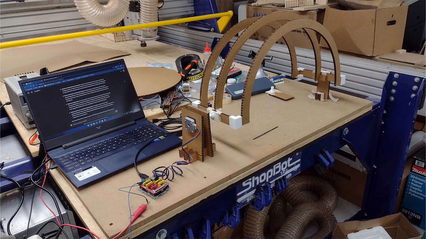
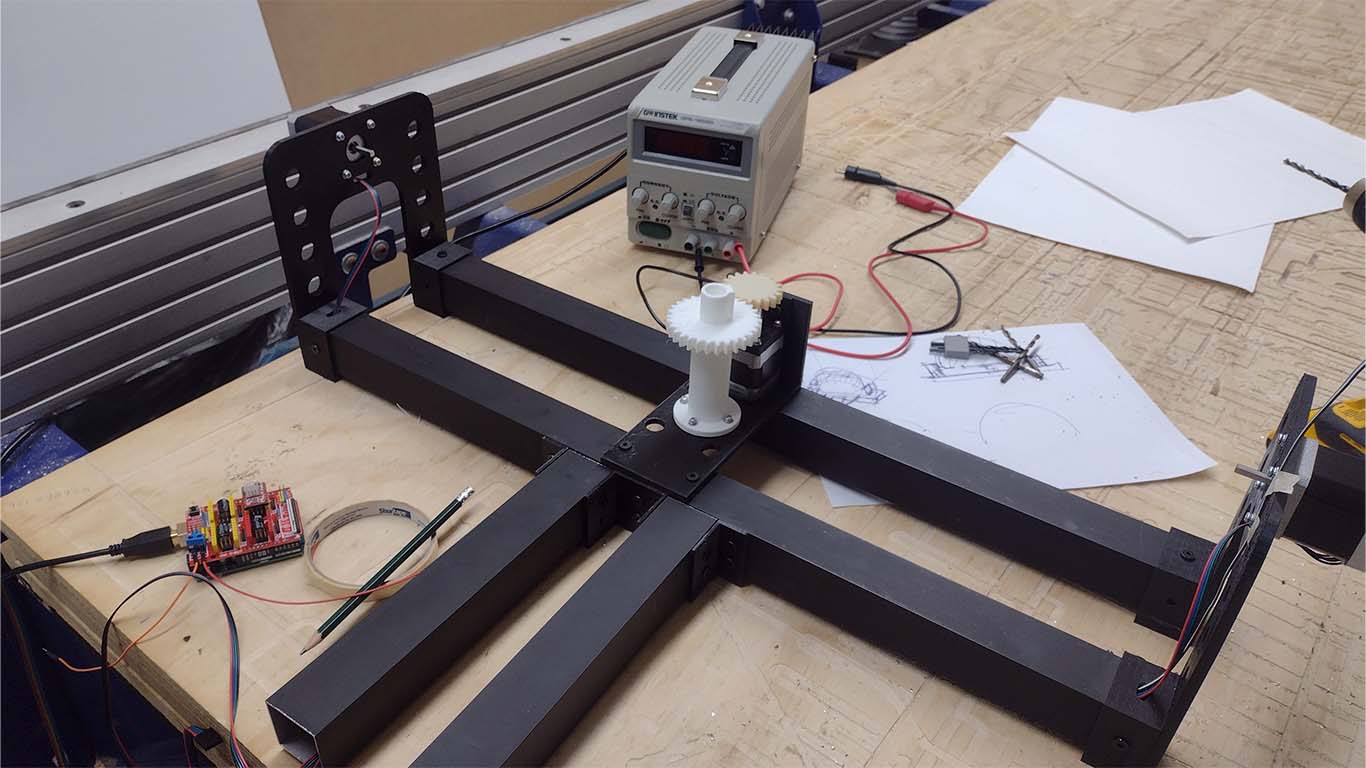
To program the rotating base, I did a quick programming of the stepper motor that was going to rotate the entire rotating circular base. First I did some programming with Arduino to see if the gear system I had designed worked, here is a sample video of how it works.
After reviewing the programming and working in parallel with the 3D printing of the gear system, I proceeded to assemble it into the structure of my device to test it. Here I will show the process and the code used for this part.
Here is a basic programming for the circular movement of the base. The idea is to test the speed and see what the ideal configuration is.
                                #include AccelStepper.h

                                    // Define pins for the X-axis motor
                                    #define X_STEP_PIN 2
                                    #define X_DIR_PIN 5
                                    #define X_ENABLE_PIN 8

                                    // Create an instance of the AccelStepper library
                                    AccelStepper stepperX(AccelStepper::DRIVER, X_STEP_PIN, X_DIR_PIN);

                                    void setup() {
                                      // Configure the motor enable pin
                                      pinMode(X_ENABLE_PIN, OUTPUT);
                                      digitalWrite(X_ENABLE_PIN, LOW); // Activate the motor

                                      // Set the motor's maximum speed and acceleration
                                      stepperX.setMaxSpeed(1000); // Adjust as necessary
                                      stepperX.setAcceleration(1000); // Adjust as necessary

                                      // Start moving forward
                                      stepperX.moveTo(10000);
                                    }

                                    void loop() {
                                      // Move the motor towards the target position
                                      stepperX.run();

                                      // If the target position is reached, reverse direction
                                      if (stepperX.distanceToGo() == 0) {
                                        stepperX.moveTo(-stepperX.currentPosition());
                                      }
                                    }
After programming and correcting some errors that were present, the idea is to see the speed and if it is possible to move things. Here is a video of the development
The speed settings and gear system worked correctly. Here is a video placing a small architectural test model and the entire correct system. Now I have to decrease and add a potentiometer to move according to the user's need at a standard speed. And on the other hand, all that remains is to unite all the programming for the final project.
DESIGNING AND MILLING MY BOARD - KICAD
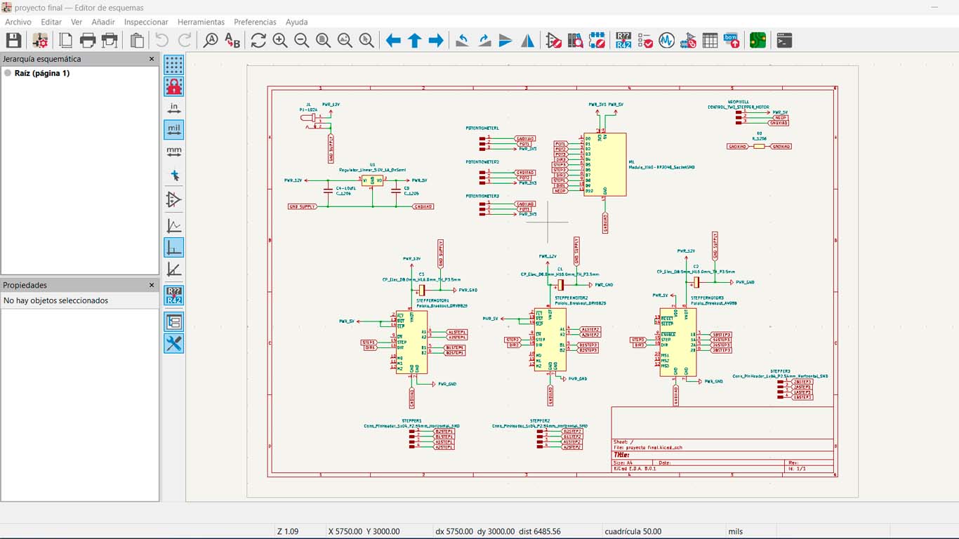
After having all the programming and connections made in the previous spirals, it was time to design my board that contains all the components for the final project. To do this, I started designing the plates in KICAD , which is the program I was using throughout the fab academy. Here are some screenshots of the design.
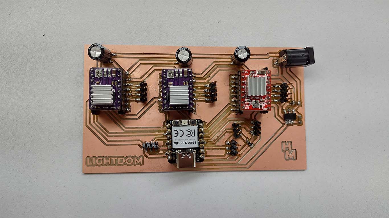
First I started with the schematic design of the project where I chose to use the XIAO RP2040 microcontroller, 1 A4988 driver and 2 DRV8825 drivers for the stepper motors. Each of them together with the neopixels controlled by 3 potentiometers that will have their function of moving the arc, the circular base and the location of the light in the neopixels. Here is a screenshot of the schematic design.
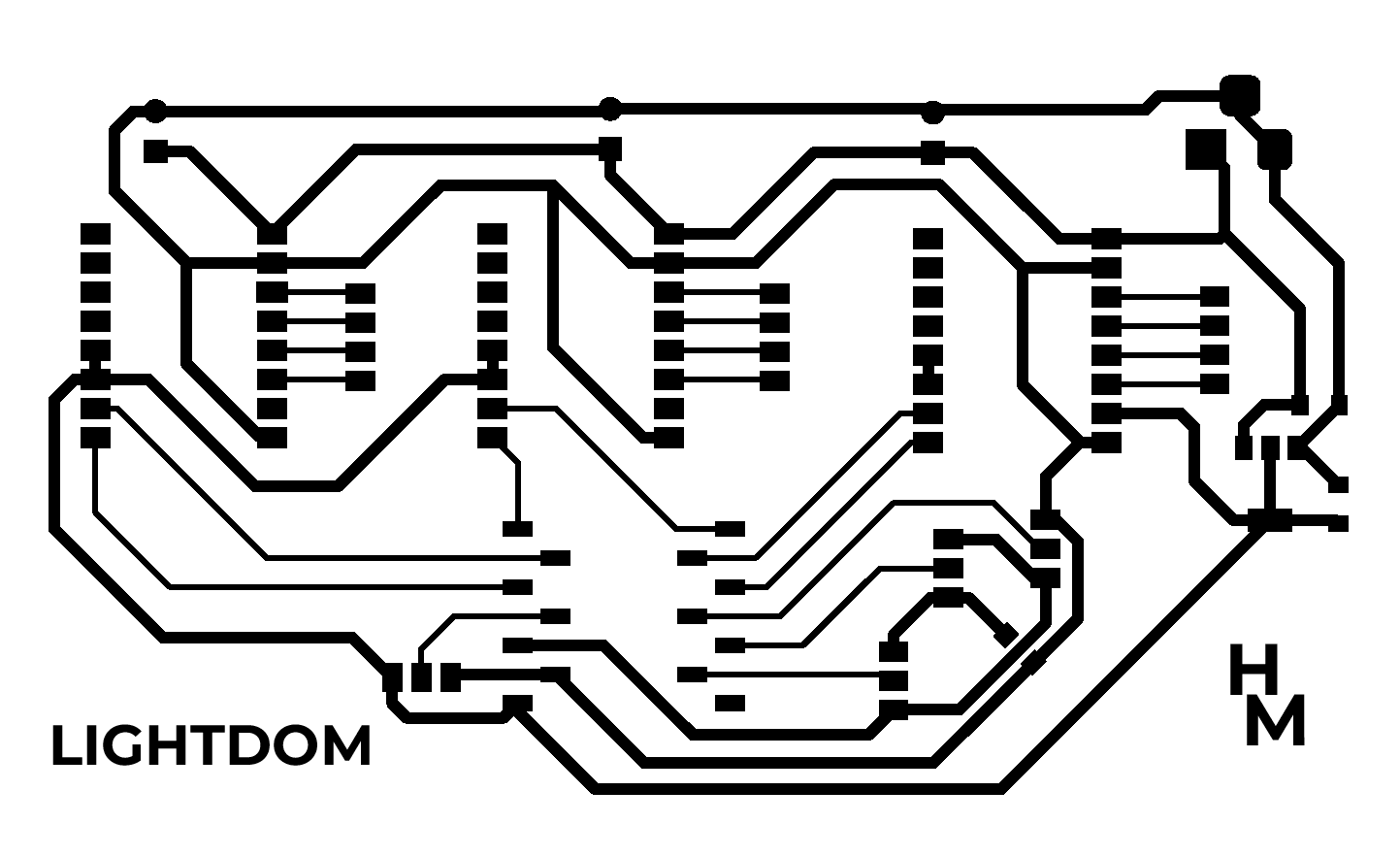
Then I began to develop the design of the plate for milling. For the GND, 5V and 3V3 tracks I used track widths of 1mm and for the data I used track widths of 0.5mm. The other components were important and are placed as requested by the datasheets for each component used.
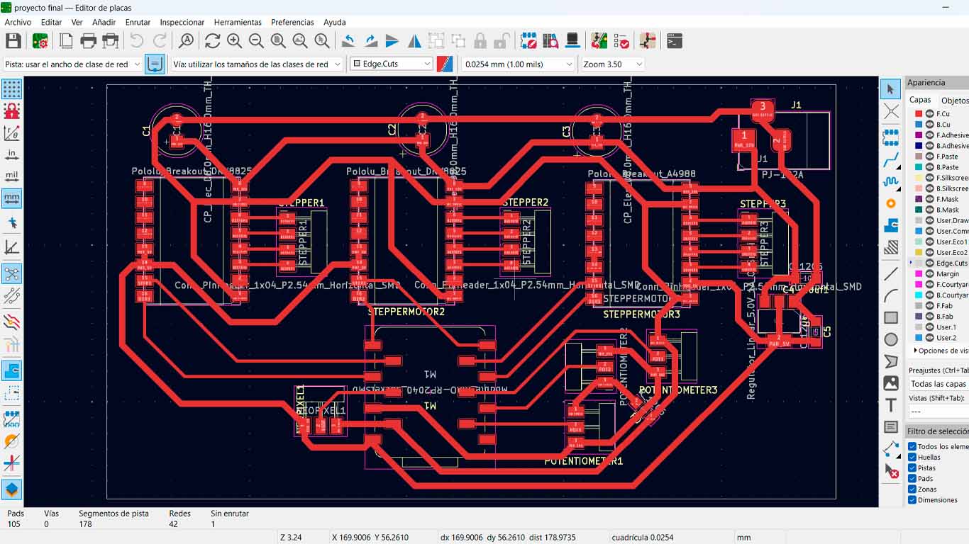
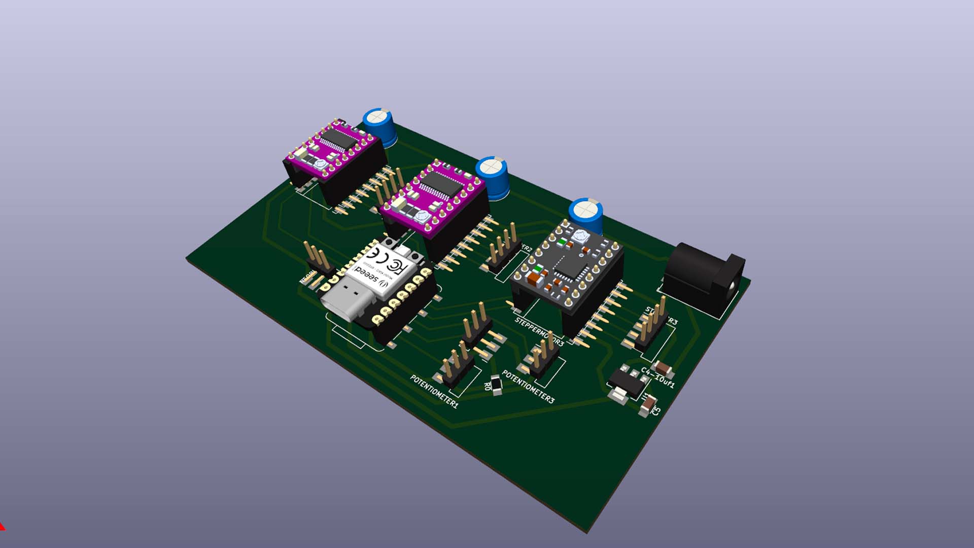
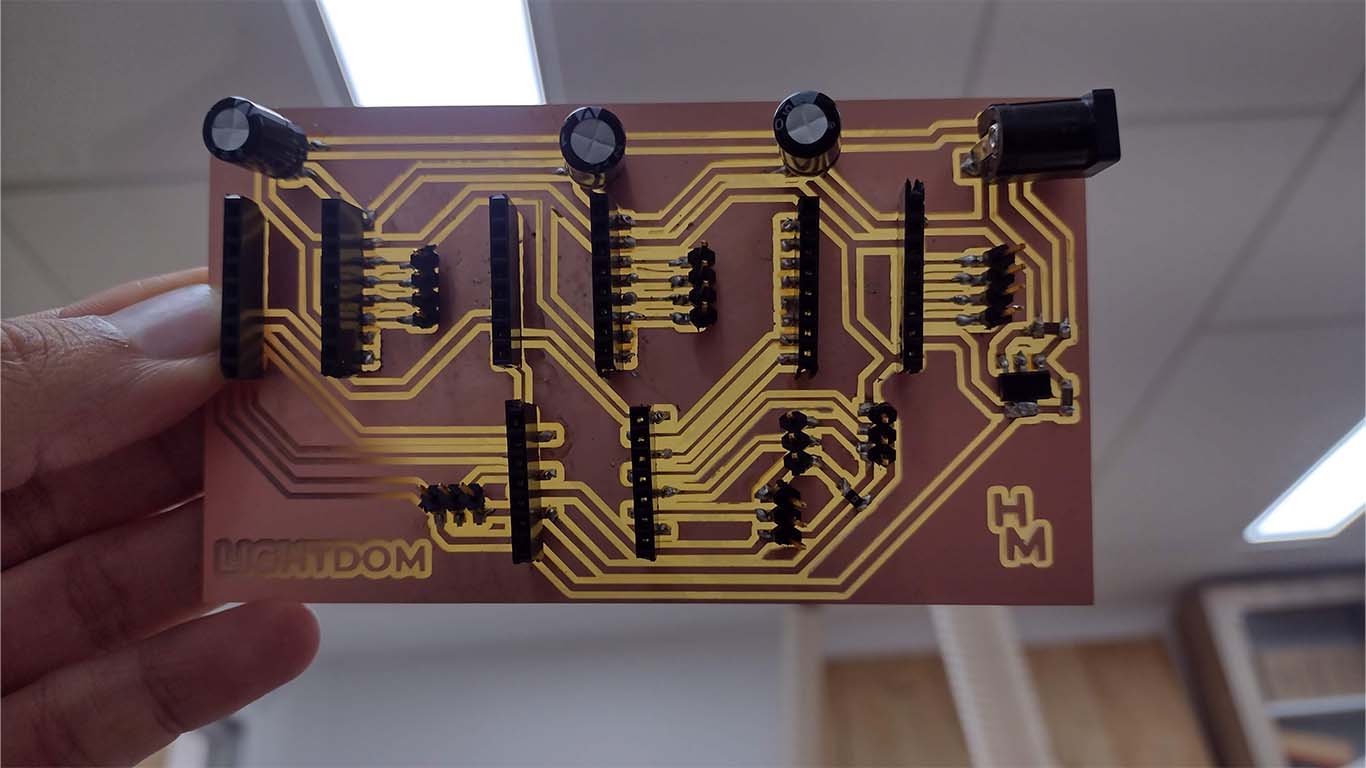
After having the design in KICAD, we exported it in PNG and I added the name of my project on the plate also so that it can be milled. Here are the traces and the interior of the plate designed and ready to mill in MODS.CE


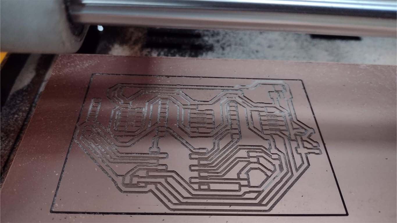
After obtaining the files, we moved on to milling the tracks first. Here is a small video of the MONOFAB SRM20 machine milling the tracks of my board.
On the other hand, we had the edge of the plate cut 1/32 with the milling cutter and it would be ready for welding components. Here is a small video.
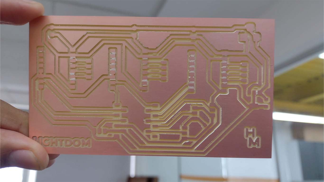
Here are some photographs of the final result of the LIGHTDOME board ready for soldering the components to be used.
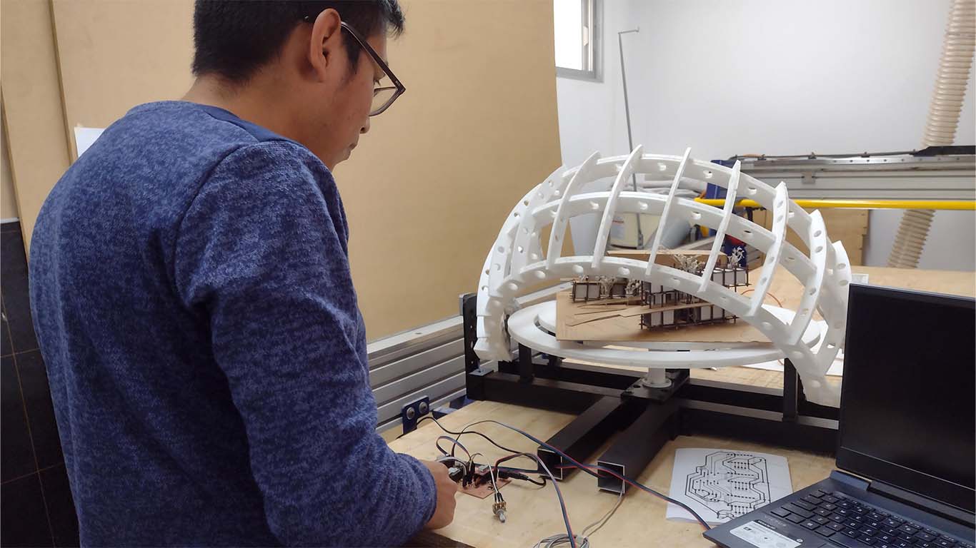
After obtaining the board I began to solder all my electrical components, in this case I placed the connectors, capacitors and resistors that were very complicated to solder due to the quantity. Here are some photographs.
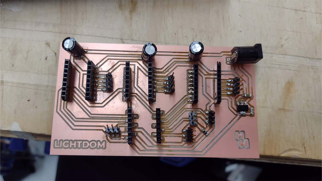
After soldering all the components and placing the drivers such as the microcontroller, here is the result of my design of my final board. It turned out very beautiful and I was excited to see the result of so much learning.
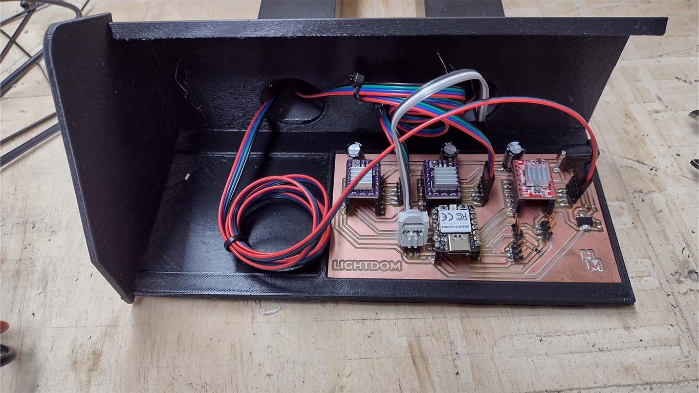
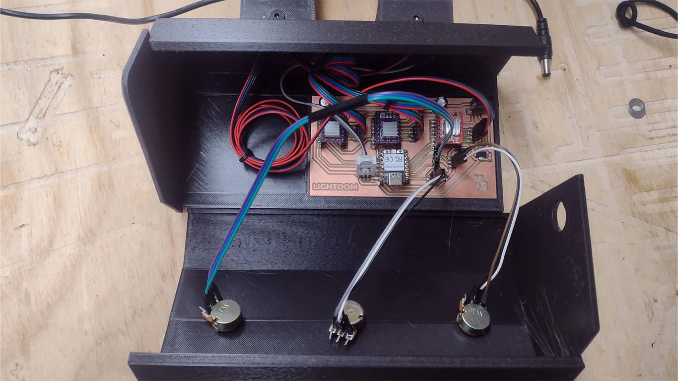
Finally, to complete the design and welding of components, I began to connect all my devices such as stepper motors and potentiometers in a box to have the entire system integrated and ready for the entire final project to operate.
PROGRAMMING
After having the board and components connected. I worked on the programming code to be able to carry out all the movements of the inputs and outputs that I am using in the ARDUINO IDE. When previously making the spirals they helped me understand what the programming of each component was like, the idea is to put them all together and make them all work according to the assigned task. It was achieved and here I leave the programming code used for LIGHTDOME
                                #include Adafruit_NeoPixel.h

                                    // Pin configuration
                                    #define STEP_PIN_1 2
                                    #define DIR_PIN_1 4
                                    #define STEP_PIN_2 7
                                    #define DIR_PIN_2 6
                                    #define STEP_PIN_3 0
                                    #define DIR_PIN_3 1
                                    #define POT_PIN 27
                                    #define POT_PIN_2 28
                                    #define PIN_POT 29
                                    #define PIN_NEOPIXEL 3
                                    #define NUM_PIXELS 75  // Total number of NeoPixels
                                    #define GROUP_SIZE 3   // Size of the group of LEDs lit simultaneously

                                    // Arc definitions
                                    #define ARC1_START 0
                                    #define ARC1_END 24
                                    #define ARC2_START 25
                                    #define ARC2_END 48
                                    #define ARC3_START 49
                                    #define ARC3_END 74

                                    #define NUM_READINGS 20 // Number of potentiometer readings to average
                                    #define POT_THRESHOLD 10 // Threshold to detect potentiometer movement

                                    Adafruit_NeoPixel strip = Adafruit_NeoPixel(NUM_PIXELS, PIN_NEOPIXEL, NEO_GRB + NEO_KHZ800);

                                    int currentPosition1 = 0; // Variable to store the current position of the first stepper
                                    int currentPosition2 = 0; // Variable to store the current position of the second stepper
                                    int lastPotValue = 0; // Last potentiometer value read

                                    void setup() {
                                      pinMode(STEP_PIN_1, OUTPUT);
                                      pinMode(DIR_PIN_1, OUTPUT);
                                      pinMode(STEP_PIN_2, OUTPUT);
                                      pinMode(DIR_PIN_2, OUTPUT);
                                      pinMode(STEP_PIN_3, OUTPUT);
                                      pinMode(DIR_PIN_3, OUTPUT);
                                      pinMode(PIN_POT, INPUT);

                                      strip.begin();
                                      strip.show();  // Initialize all LEDs off

                                      moveStepper1(currentPosition1);
                                      moveStepper2(currentPosition2);
                                      // Motor 3 starts off, does not move in setup
                                    }

                                    void loop() {
                                      // Stepper motor control
                                      int potValueTotal = 0;
                                      for (int i = 0; i < NUM_READINGS; i++) {
                                        potValueTotal += analogRead(POT_PIN);
                                        delay(1); // Small delay to stabilize the ADC reading
                                      }
                                      int potValue1 = potValueTotal / NUM_READINGS;

                                      int potValue2 = analogRead(POT_PIN_2);

                                      if (abs(potValue2 - lastPotValue) > POT_THRESHOLD) {
                                        int stepsToMove3 = abs(potValue2 - lastPotValue);
                                        digitalWrite(DIR_PIN_3, potValue2 > lastPotValue ? HIGH : LOW);
                                        moveStepper3(stepsToMove3);
                                        lastPotValue = potValue2;
                                      }

                                      int stepperSteps1 = map(potValue1, 0, 1023, 0, 100);
                                      moveStepper1(stepperSteps1);
                                      moveStepper2(stepperSteps1);

                                      // LED control
                                      int potValue = analogRead(PIN_POT);  // Returns a value between 0 and 1023

                                      if (potValue < 10) {  // A low threshold to consider as the initial position
                                        for (int i = 0; i < NUM_PIXELS; i++) {
                                          strip.setPixelColor(i, 0, 0, 0);
                                        }
                                        strip.show();
                                      } else {
                                        int position = map(potValue, 0, 1023, 0, NUM_PIXELS - 1);
                                        if (position <= ARC1_END) {
                                          updateLeds(position, ARC1_START, ARC1_END);
                                        } else if (position <= ARC2_END) {
                                          position = ARC2_START + (position - ARC1_END - 1);
                                          updateLeds(position, ARC2_START, ARC2_END);
                                        } else {
                                          position = ARC3_START + (position - ARC2_END - 1);
                                          updateLeds(position, ARC3_START, ARC3_END);
                                        }
                                      }

                                      delay(15); // Adjust this value according to the desired movement speed
                                    }

                                    void moveStepper1(int steps) {
                                      int stepsToMove = steps - currentPosition1;

                                      if (stepsToMove != 0) {
                                        digitalWrite(DIR_PIN_1, stepsToMove > 0 ? HIGH : LOW);
                                        stepsToMove = abs(stepsToMove);

                                        for (int i = 0; i < stepsToMove; i++) {
                                          digitalWrite(STEP_PIN_1, HIGH);
                                          delayMicroseconds(100); // Adjust this value according to the desired movement speed
                                          digitalWrite(STEP_PIN_1, LOW);
                                          delayMicroseconds(100); // Adjust this value according to the desired movement speed
                                        }

                                        currentPosition1 = steps;
                                      }
                                    }

                                    void moveStepper2(int steps) {
                                      int stepsToMove = steps - currentPosition2;

                                      if (stepsToMove != 0) {
                                        digitalWrite(DIR_PIN_2, stepsToMove > 0 ? LOW : HIGH); // Opposite direction to motor 1
                                        stepsToMove = abs(stepsToMove);

                                        for (int i = 0; i < stepsToMove; i++) {
                                          digitalWrite(STEP_PIN_2, HIGH);
                                          delayMicroseconds(100); // Adjust this value according to the desired movement speed
                                          digitalWrite(STEP_PIN_2, LOW);
                                          delayMicroseconds(100); // Adjust this value according to the desired movement speed
                                        }

                                        currentPosition2 = steps;
                                      }
                                    }

                                    void moveStepper3(int steps) {
                                      for (int i = 0; i < steps; i++) {
                                        digitalWrite(STEP_PIN_3, HIGH);
                                        delayMicroseconds(3000); // Adjust this value according to the desired movement speed
                                        digitalWrite(STEP_PIN_3, LOW);
                                        delayMicroseconds(3000); // Adjust this value according to the desired movement speed
                                      }
                                    }

                                    void updateLeds(int position, int arcStart, int arcEnd) {
                                      for (int i = 0; i < NUM_PIXELS; i++) {
                                        strip.setPixelColor(i, 0, 0, 0);
                                      }

                                      int limitedPosition = max(arcStart, min(position, arcEnd - GROUP_SIZE + 1));

                                      for (int i = 0; i < GROUP_SIZE; i++) {
                                        if (limitedPosition + i <= arcEnd) {
                                          strip.setPixelColor(limitedPosition + i, strip.Color(255, 255, 255));  // Full brightness white
                                        }
                                      }

                                      strip.show();
                                    }
LATEST TESTS
For the last part of the development of my project I wanted to check that everything is going well in case there were any connection or soldering problems since there were times when the servomotors did not synchronize. Here I attach a video of a test carried out where we can see that the stepper motors lost power when raising the arc, however it was because the rotation of the potentiometer was very fast. I try again to use the entire device and it works. It was a very stressful week but it was possible.
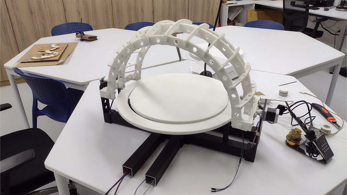
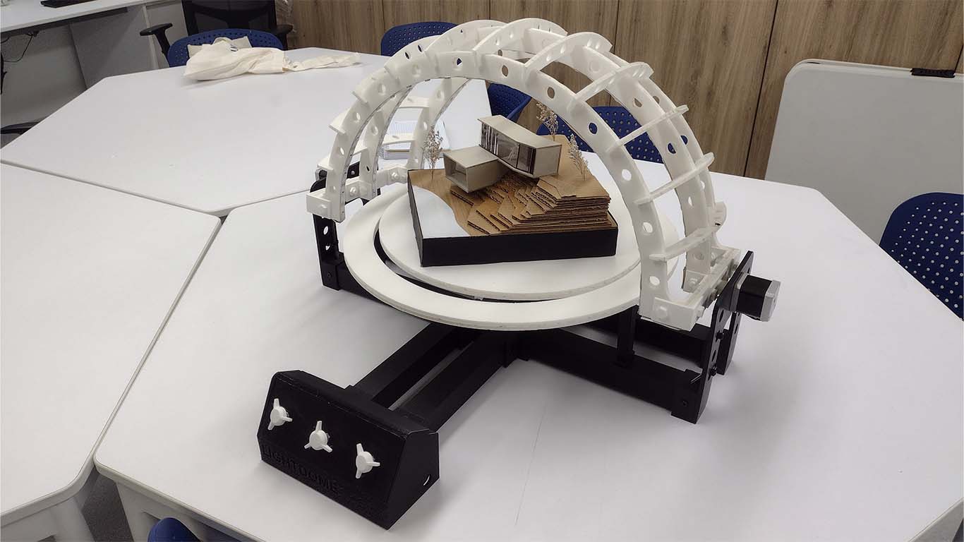
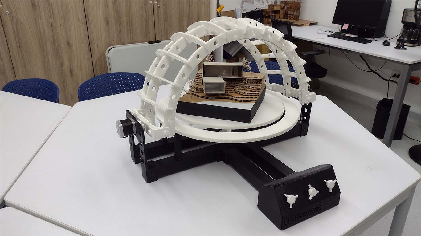
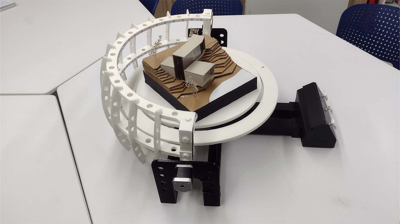
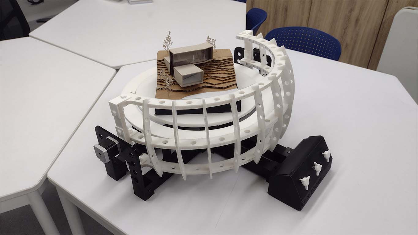
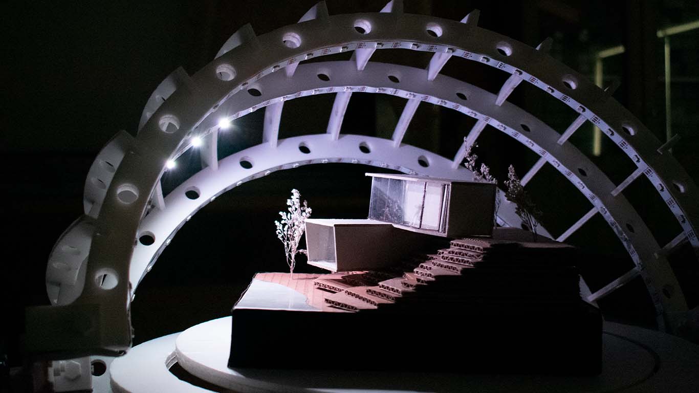
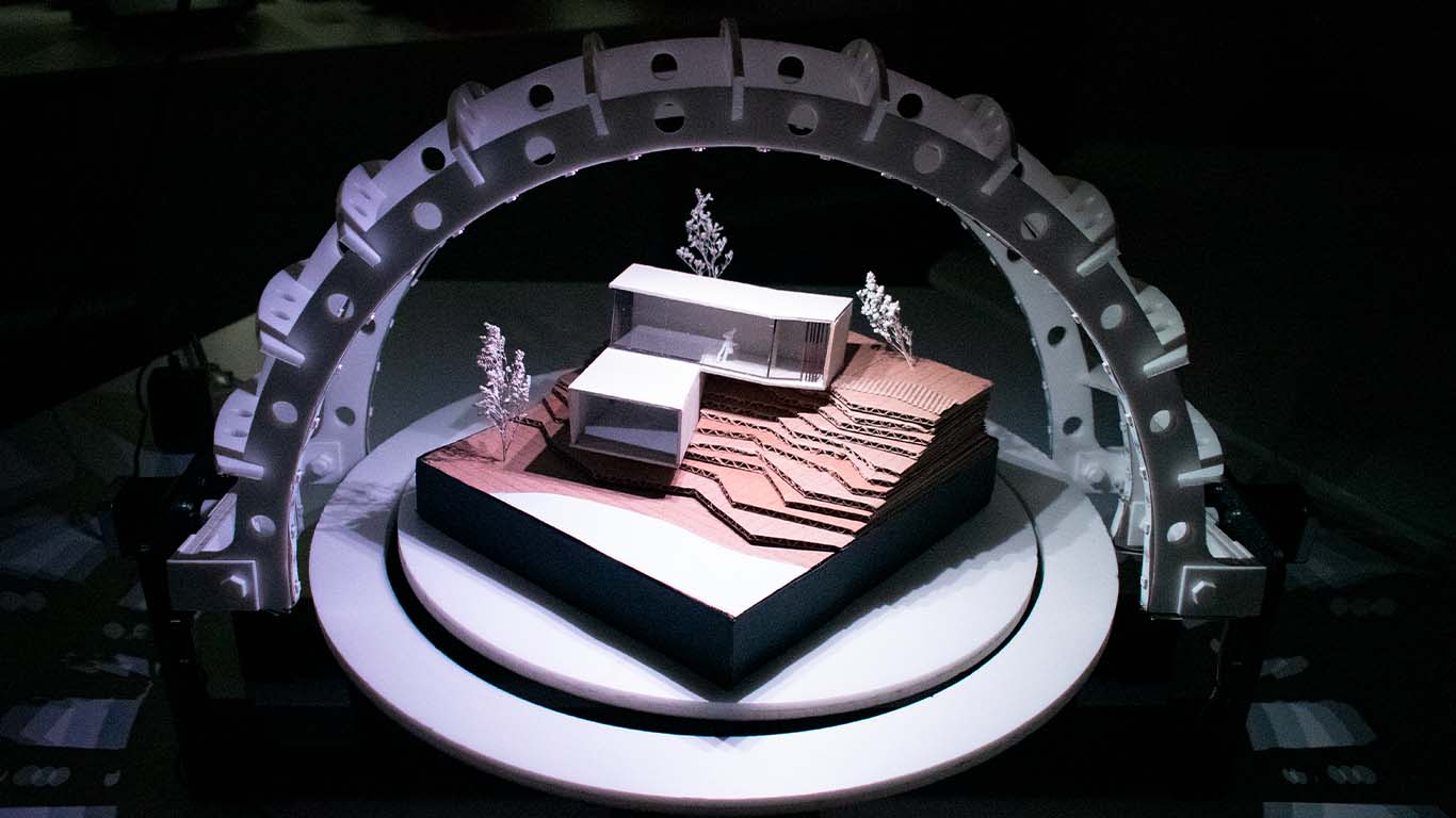
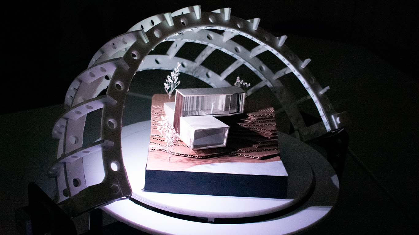
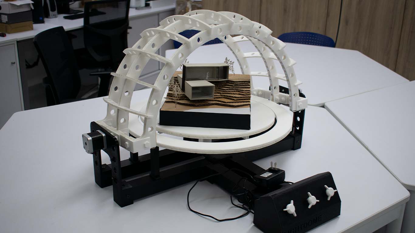
After testing the movement of the arches, I now wanted to test the 3 processes that comprise my final project. The movement of the arches, the movement of the circular base and the neopixels. Here is a photograph and a video of the tests carried out to see how the project works.
At the end and solving the different connection, operation, programming problems and finishing with some pending items that I was missing such as 3D printing parts and components. I can conclude that everything works correctly, in the next section I am going to post some videos and photographs of the project.
FINAL RESULT
RESULTS
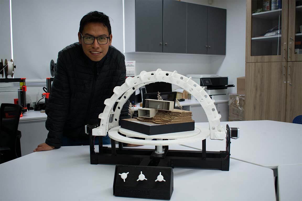
In the next section, I am going to show some photos and videos of the result of my final project.
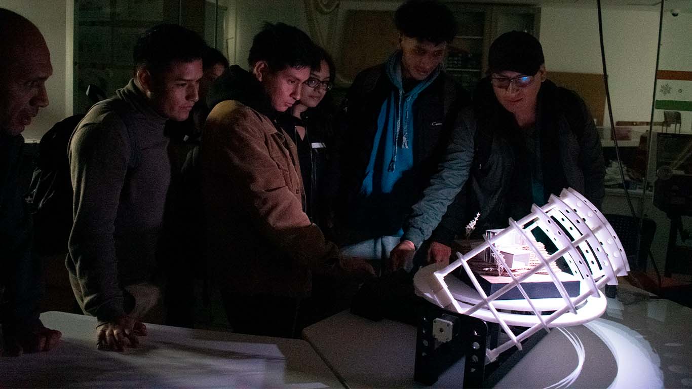
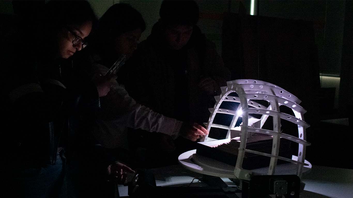
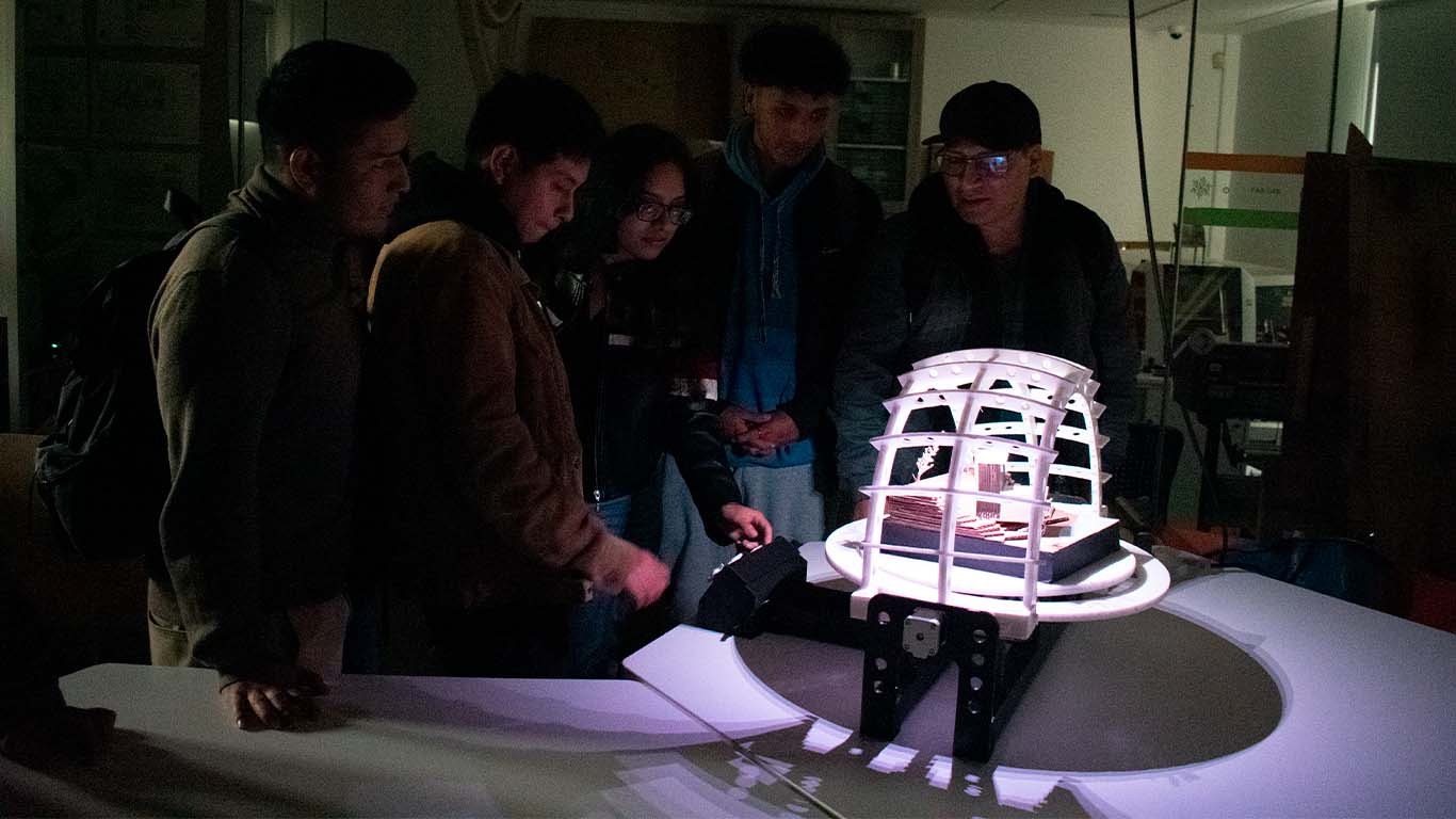
Likewise, some students tested the device and wanted to use it, here are some photographs and videos analyzing the new device for the architecture degree.

GALLERY
QUESTIONS AND ANSWERS
What tasks have been completed, and what tasks remain?
I consider that all the tasks I had at the beginning could be completed. I have to be realistic that at first I wanted to achieve a device that has WIFI communication and another way of working. However, it is possible, the idea has been made and now it is a matter of continuing to generate spirals after spirals until we achieve a better device. He was able to conclude with the question that all the tasks were completed and all were achieved for the final delivery.
What's working? what's not?
In the final project everything works, from each component, each input and output device. Only during the development of the project were there some complications because there were times where some component, mainly the stepper motors, had connectivity problems and did not read the potentiometer readings. I think it was a welding and connection error of the components, however I can confirm that even the spiral developed, everything works.
What questions need to be resolved?
In order to carry out my final project we need to learn how to calculate the reference voltage value of the drivers. This step is important since, since the project has 3 stepper motors, it is important to know and manage the calculation of each of them taking into account their datasheet. On the other hand, it is important to mention that I used aluminum for the base of my project since it is light and you have to have knowledge of using machines to cut them and drill them for the screws. Finally, I think we know the other processes as laser cutting, 3D printing, electronic design and programming since they are the processes that I use the most for my project.
what will happen when?
If the question refers to the future, my idea is to improve my final project as much as I can until I achieve a very technological device that can work through apps and Wi-Fi. My idea is to maintain the work and continue increasing spirals until achieving the final goal of converting the project into a technological one. I have always said and they have recommended to me that every project has no end, it always makes you want to improve it a little more and that is what I will do. The idea is to achieve a more technological project based on learning from the FAB ACADEMY.
what have you learned?
To answer this question I would have to make a comparison with the HANS that began the course. I consider that I have learned a lot about all the processes involved in digital manufacturing. I could see that each assignment has a purpose of learning something more and that during the development process of my final project I have understood it. I learned many more things about programming, design and work methodology. The SPIRAL and PARALLEL methodologies seem very correct to me for the FAB ACADEMY, because they help us see that everything can be achieved little by little and that at the same time you can develop other processes and that by combining we achieve wonderful things. Here I thank the teacher ADRIAN TORRES , who from the beginning I met him told me how important the work methodology they recommend is and obviously the project management with the time we give to each spiral and process. Everything is important and it has been a very important few months where I have learned a lot and that will now help me improve my performance in the subject and also in the work methodology.
FILES
Here you can download all the files that I have made for the final project: