This week's assignment was:
ASSIGNMENT
- Propose a final project masterpiece that integrates the range of units covered, answering:
ORGANIZATION
Here I show how I organized myself for this week.
| Wednesday 22th: | Fab Academy classes, organization of the week and review of documentation from colleagues from previous years. |
|---|---|
| Thursday 23Th: | Start answering some assignment answers and research some final reference projects that could be useful for my project. |
| Friday 24th: | Development of the first 3 questions of the assignment and development of my final project. |
| Saturday 25th: | Progress in development and 3D printing of my final project |
| Sunday: 26th: | Review and spiral development of my final project. Work on processes that didn't work at first. |
| Monday 27th: | Review and correction of documentation. Update and changes for last commit. |
| Tuesday 28th: | Documentation and last commit of the week. |
ASSIGNMENT
WHAT WILL IT DO?
LIGHTDOM is an artifact inspired by the heliodon that is used to simulate the solar path and incidence anywhere in the world applied in architecture. With LIGHTDOM the idea is that any student, teacher, architecture studios and universities can replicate and have their own artifact to be able to analyze the movement of the sun and the solar incidence that their architectural projects will have. The main characteristics of LIGHTDOM is that it is light and easy to build since it is made up of materials that we can obtain very easily and that are not so heavy.
For education , the manufacture of LIGHTDOM will help students understand the movement of the sun and the importance that its analysis has in architecture for the design of architectural proposals. Nowadays, mainly in Peru, it is difficult to understand solar movement only with graphs or diagrams. However, with lightdom they will be able to see in real time the impact that their proposals, developed at the level of architectural models, have on solar incidence. In addition, it is important to know the different movements, times and hours that the sun presents throughout the year and in different parts of the world, so students will be able to understand the context and apply design strategies in their projects.
For teachers , the idea is to encourage and improve the quality of the study of bioclimatic architecture mainly at the Cientifica del Sur University, a study house that aims at sustainability and bioclimatic is part of this branch. With LIGHTDOM you will be able to explain and teach more dynamically and in a simpler way how important solar analysis is in architecture.
Finally, any professional, university or architecture studio related to architecture can manufacture and build LIGHTDOM as an analysis instrument for future projects to be designed. It is an instrument that is not limited since it is very important to have this type of artifacts to support us in the design stage and architectural studies are areas that need this type of artifacts for proposals.
WHO'S DONE WHAT BEFOREHAND?
In the FAB ACADEMY I couldn't find any reference to a HELIODON since it is the concept that I took to make LIGHTDOM, so I will show some photos from the internet that I found and some YouTube videos so that you can understand that it is a HELIODON and that I will also take from reference for my design and operation of my final project.
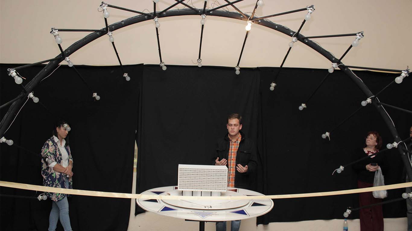
Image obtained from: HERE
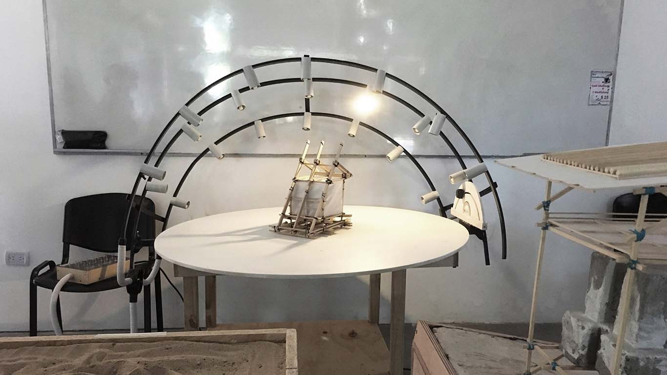
Image obtained from: HERE
Video obtained from: HERE
WHAT WILL YOU DESIGN?
My goal is to design all the parts that comprise my project. I will start with the structure that I will make of 3D PRINTING and I will combine it with ALUMINUM. I will design my ELECTRONIC BOARD, STRUCTURE JOINTS AND ARCHES. The idea is to design almost everything in my proposal and perhaps I used elements such as metal screws for the aluminum, but from there everything will be based on what I learned at the FAB ACADEMY.
WHAT MATERIALS AND COMPONENTS WILL BE USED?
STRUCTURE
ELECTRONICS
WHERE WILL COME FROM?
I recycled the structure materials such as aluminum from my dad's shop, who is a glazier. The PLA filament from my FAB LAB UCSUR and the FOAM BOARD from a local model shop. We have most of the electronic components here at the FAB LAB UCSUR, however, the stepper motors and the power supply are from a local store.
HOW MUCH WILL THEY COST?
The cost of my project is approximately 162 dollars. Mainly the cost goes into the electronic components and the structure. Here is a table to show you the cost and the links where you can purchase it in Lima, Peru.
| COMPONENTS | QUANTITY | UNITS | PRODUCT CODE | PRICE | TOTAL |
|---|---|---|---|---|---|
| XIAO RP2040 | 1 | unit | RP2040 | $9.90 | $9.90 |
| STEPPER MOTOR NEMA 17 | 3 | unit | 42BYGHW811 | $16.17 | $48.51 |
| POTENTIOMETER B50K | 3 | unit | 987-1714-ND | $1.83 | $5.49 |
| NEOPIXEL | 1 | ml | WS2812B | $13.34 | $13.34 |
| ADAPTER 12V | 1 | unit | 1225 | $4.80 | $4.80 |
| DRIVER A4899 | 1 | unit | A4899 | $2.27 | $2.27 |
| DRIVER DRV8825 | 2 | unit | DRV8825 | $3.40 | $6.80 |
| ALUMINIUM SQUARE 1 1/2" X 1 1/2" | 2 | meters | 5416 | $6.57 | $13.15 |
| BLACK PLA FILAMENT | 1 | roll | FIL10162 | $22.36 | $22.36 |
| WHITE PLA FILAMENT | 1 | roll | 1892 | $18.39 | $18.39 |
| FOAM BOARD WHITE 5 MM | 4 | sheets | 4302 | $2.10 | $8.40 |
| OTHER CONSUMABLES (wires, pin headers) | 1 | unit | 4302 | $10.00 | $10.00 |
| TOTAL APROX. | $163.41 |
WHAT PARTS AND SYSTEMS WILL BE MADE?
The objective of my project is to design each part it includes, everything will be developed according to the processes learned at the FAB ACADEMY. Here a list of the systems I can split my project and what they will develop.
WHAT PROCESSES WILL BE USED?
For the design process of my project I will use the FUSION 360 program, which is what accompanied me throughout my entire FAB ACADEMY process and makes it easier for me. From this, I will make the parts such as joints, screws and nuts based on 3D PRINTING. To design my board I will develop it in the KICAD program, where I will use MODS to mill the board together with the soldering process of my components. Finally, to program my microcontroller I will use the ARDUINO IDE.
WHAT QUESTIONS NEED TO BE ANSWERED?
During these weeks for the development of my final project I hope to learn more about the spiral and parallel methodology. I find the methodology very interesting and at the same time it seems complicated to adapt and apply when you already have your own methodology that you have always applied. On the other hand, I want to learn how servomotors work together with potentiometers, which are components that I did not have the opportunity to work on in the weeks of output and inputs devices. Finally, learn to develop a good integration system between all the components and together with the parts of the project.
HOW WILL IT BE EVALUATED?
Here I want to make reference to the teacher ADRIAN TORRES, who is a wonderful person who supports me at the FAB ACADEMY. And as I always told myself, I have to work in a SPIRAL AND PARALLEL, so here I show the way in which I began to evaluate my progress using the spiral methodology.
FINAL PROJECT
SECOND SPIRAL
In week 17, I began to develop the second spiral that the goal was to have most of the processes almost ready for final delivery. This week was difficult since it was a week of more mistakes than successes, where every progress I made felt like I was achieving nothing. Here is a summary of the entire process carried out for the second spiral.
LASER CUTTING
For the laser cutting process, I carried out a small analysis on the materials and their weight so that the torque that the stepper motors have can work normally. You can review that on my PROJECT DEVELOPMENT page. After carrying out the analysis I choose FOAM, a light material that is aesthetically better than cardboard. After that and with the help of 2D and 3D design, I laser cut a prototype taking into account all the characteristics that I would need to reduce its weight and for its assembly with 3D printing.
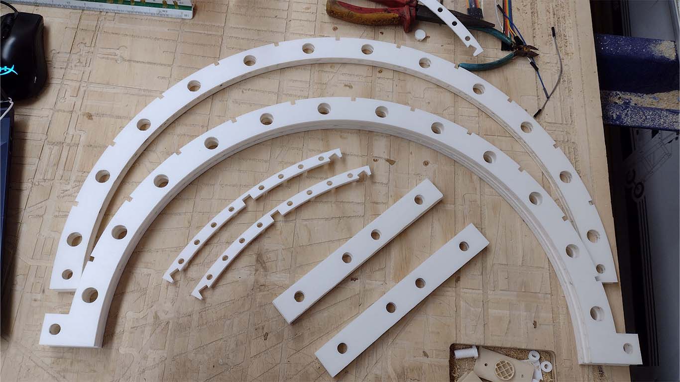
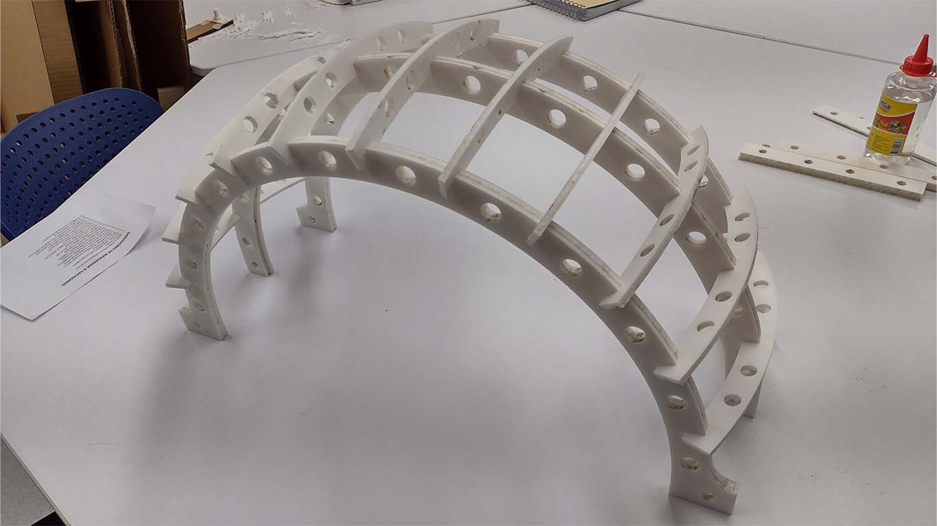
After having the foam pieces cut on a laser cutter, I went on to assemble the entire arch structure that comprises my project. Everything was going to be press-fit and only the lower part of the strip and the axis will be 3D printed. Here is a photograph of the assembled structure.
3D PRINTING
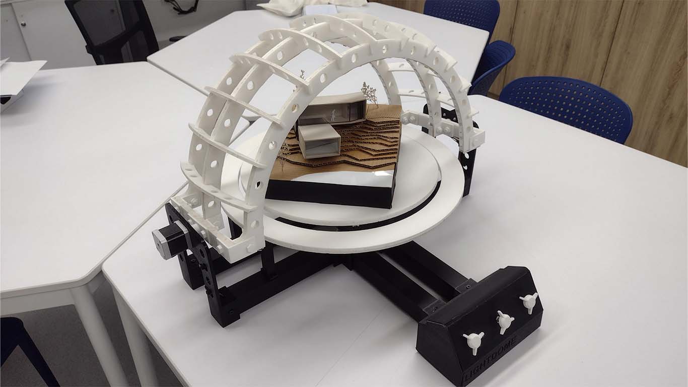
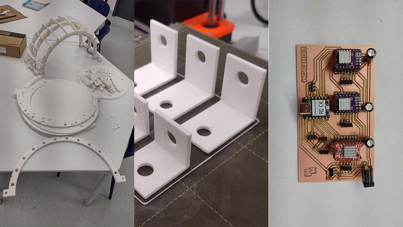
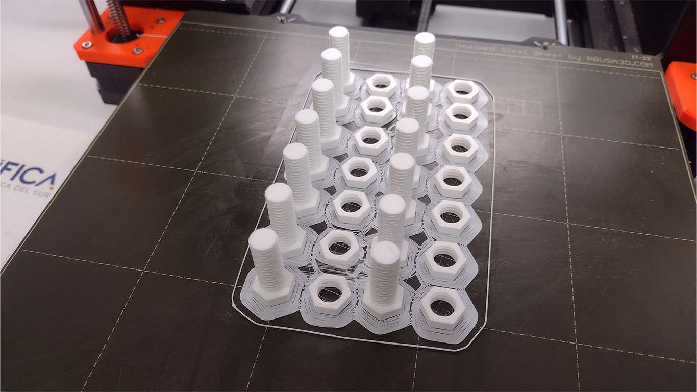
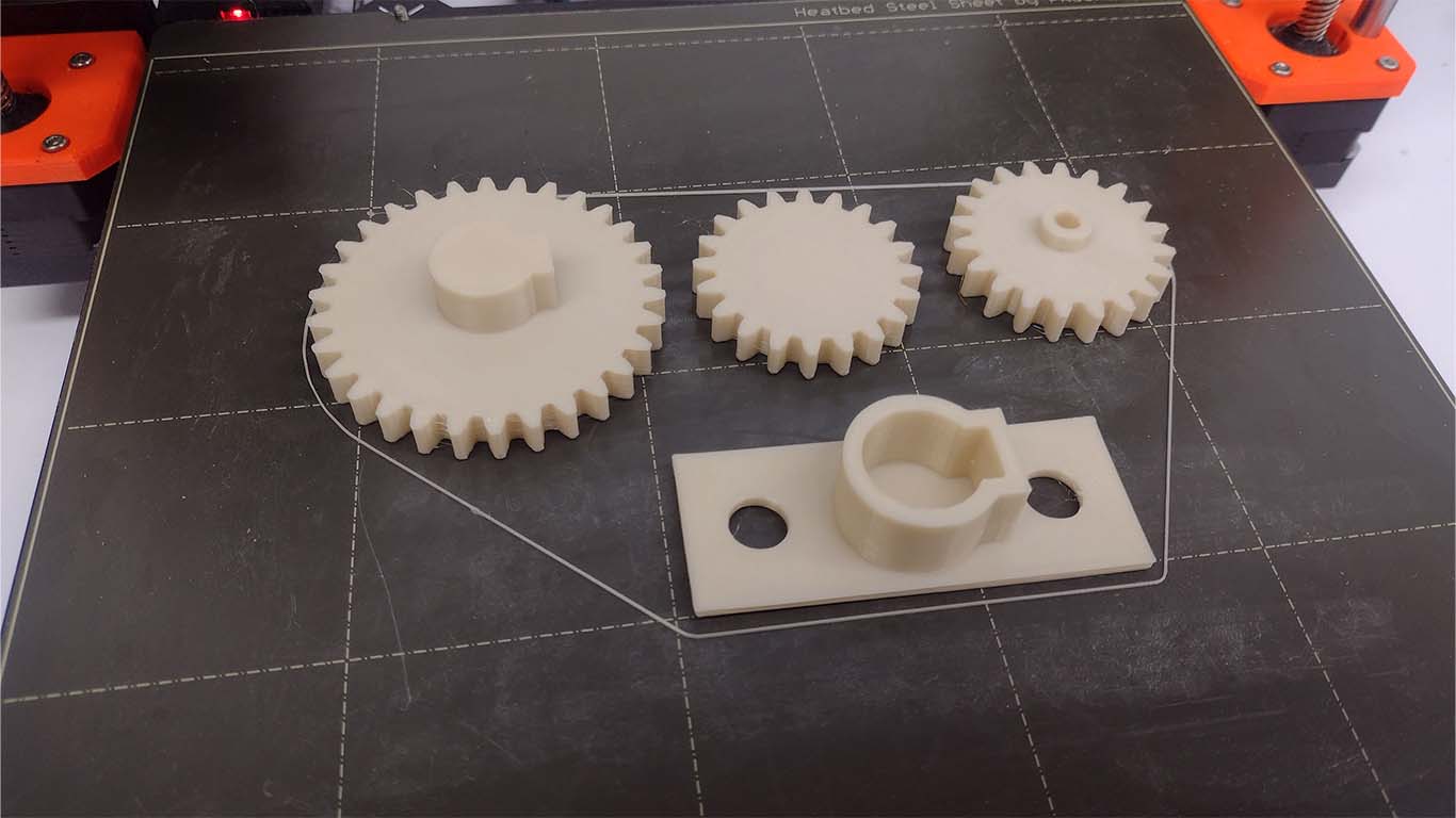
For 3D printing, after trying to work with pressure and seeing that it did not work as I wanted, I moved on to developing connections using bolts and accessories in 3D printing. I liked how it looked and I started making all the accessories in white PLA filament, the idea was that the entire structure of the arches was light due to the torque presented by the stepper motors and the best idea was to work with 3D printing. Here are some photographs of the components mentioned and developed in this second spiral.
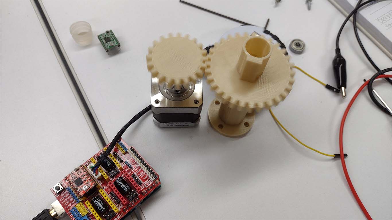
I also began to work with the gear system in regards to the circular base that was going to have a movement to change the orientation of the models. For this it was not going to be enough to use a stepper motor directly due to the lack of strength, so they recommended using a gear system to increase the touch and move any model that is on top. Therefore, I started working with 3D design and printing. Here are some photographs of it.
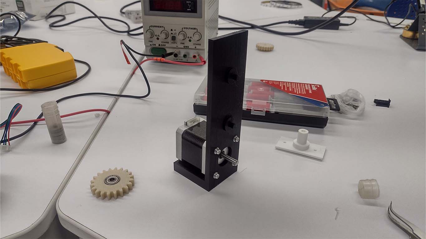
Finally, I began to work with the general structure of the entire device, the idea was that it had lateral supports for both the arches and also for the entire device. At first it was only thought of with a simple design where we would have the stepper motor at the bottom, however it did not work due to the principle of the 3 arcs that were not going to reach values of 0 or 180°. Here is a photograph of my first proposal.
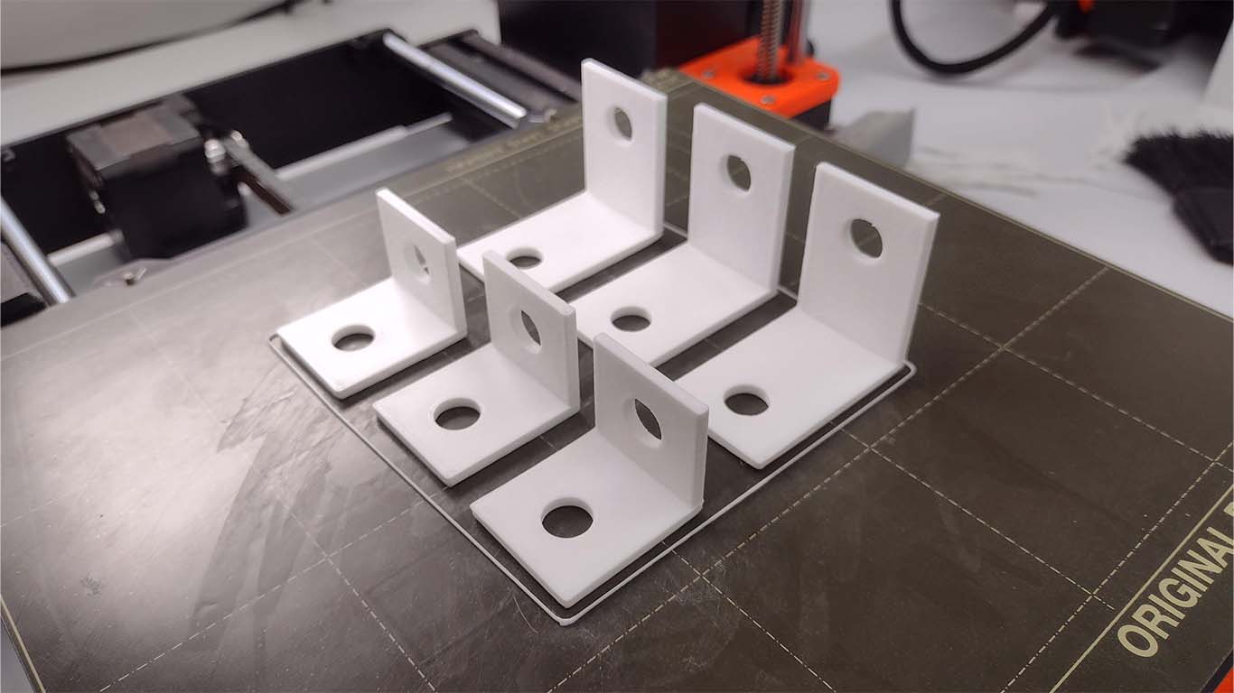
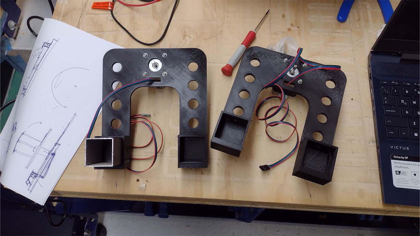
For the next design, I had to raise the stepper motor since it was located in the axes of the arch structure and was going to be elevated, so a base was designed for both the arch and also so that it can receive all the structure that was going to comprise the artifact. Here the fine printed design of the side supports, where the aluminum of the base and the structure of the arches are connected.
ELECTRONIC DESIGN
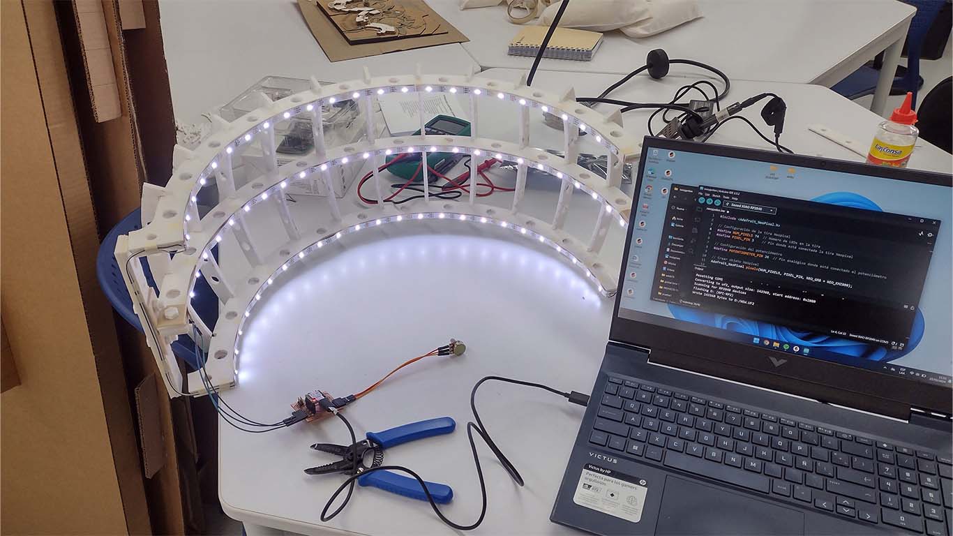
For the electronic part for the second spiral, the idea was to connect the neopixels and the stepper motors and observe if they were working correctly according to what was done in the first spiral. First all the neopixels that simulate sunlight were placed and we can turn everything on so that we can see if all the connection and power was correct.
RESULT
For the second spiral I was able to complete the tasks and close some such as the design and the laser cutting since everything was fine. I still have to do certain things but it was a week of learning, of failures and also successes, sometimes I feel that they were few but the idea is to continue moving forward and discovering more errors to give solutions and that is why I rely a lot on both the SPIRAL and the SPIRAL methodologies. PARALLEL since you are discovering and also achieving certain processes that are necessary, Here is a video summary of what was achieved for this week and I would be ready for the last spiral of my final work.