This week's assignment was:
- Design and document the system integration for your final project
ORGANIZATION
Here I show how I organized myself for this week.
| Wednesday 15th: | Fab Academy classes, organization of the week and review of documentation from colleagues from previous years. |
|---|---|
| Thursday 16Th: | Design of sketches and proposal for the distribution of cables and plates of the final project. |
| Friday 17th: | Design circuits for my final project and know the distribution of electrical components. |
| Saturday 18th: | Enter GLOBAL OPEN TIME to show my mistakes and ask some questions about the assignment of the week. Critique of my final project. |
| Sunday: 19th: | Case design for my final project board |
| Monday 20th: | Review and correction of documentation. Update and changes for last commit. |
| Tuesday 21th: | Documentation and last commit of the week. |
ASSIGNMENT
MAKING MY SYSTEM INTEGRATION
To develop my integration system for my final project I had to do it in parts because it was very easy for me to understand my project and with the support of ADRIAN TORRES, he recommended that I could work in a spiral to understand the components that I am going to use and how it will work to work to achieve in the end an entire integrated system.
STEPPER MOTOR SYSTEM
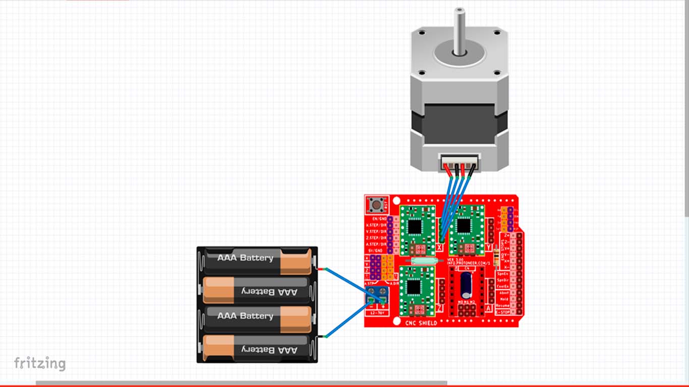
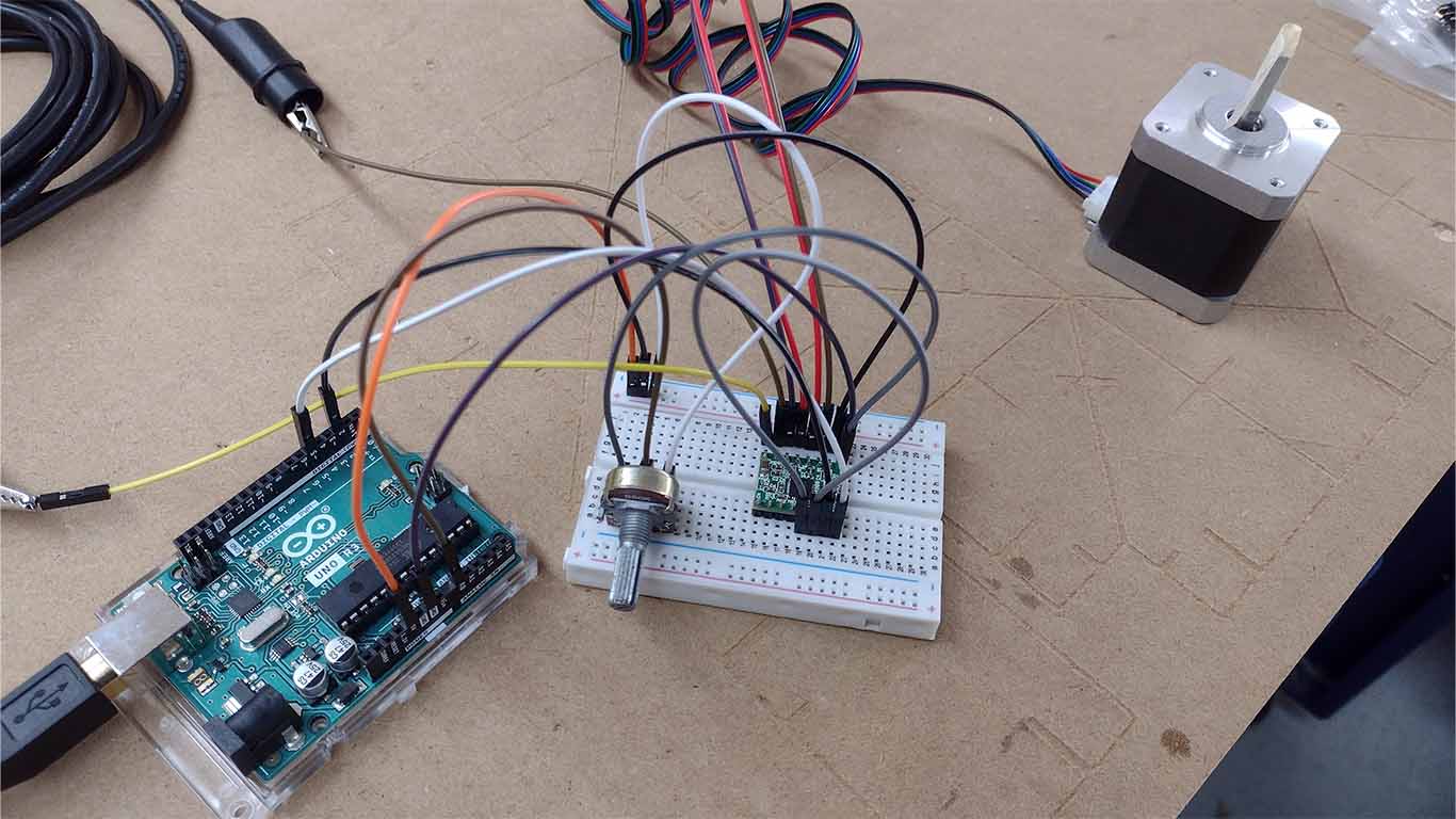
I began to develop my integrated system with basic connections from basic components that we have in the fab lab to know how it works and the components that are needed to develop what I am looking for in my final project. In my case, I began to develop the connection and programming of my stepper motors, where it helped me a lot to understand how many pins I will need for my board. For this case I used the ARDUINO UNO because it is much easier to make the connection and with a PROTOBOARD to achieve operation. Here is a diagram of my connections and how I began to develop this first element of my system.
Here is a small simulation of my first spiral connection and programming of the stepper motor with the ARDUINO CNC SHIELD V3 for its operation and to understand what it needs to work.
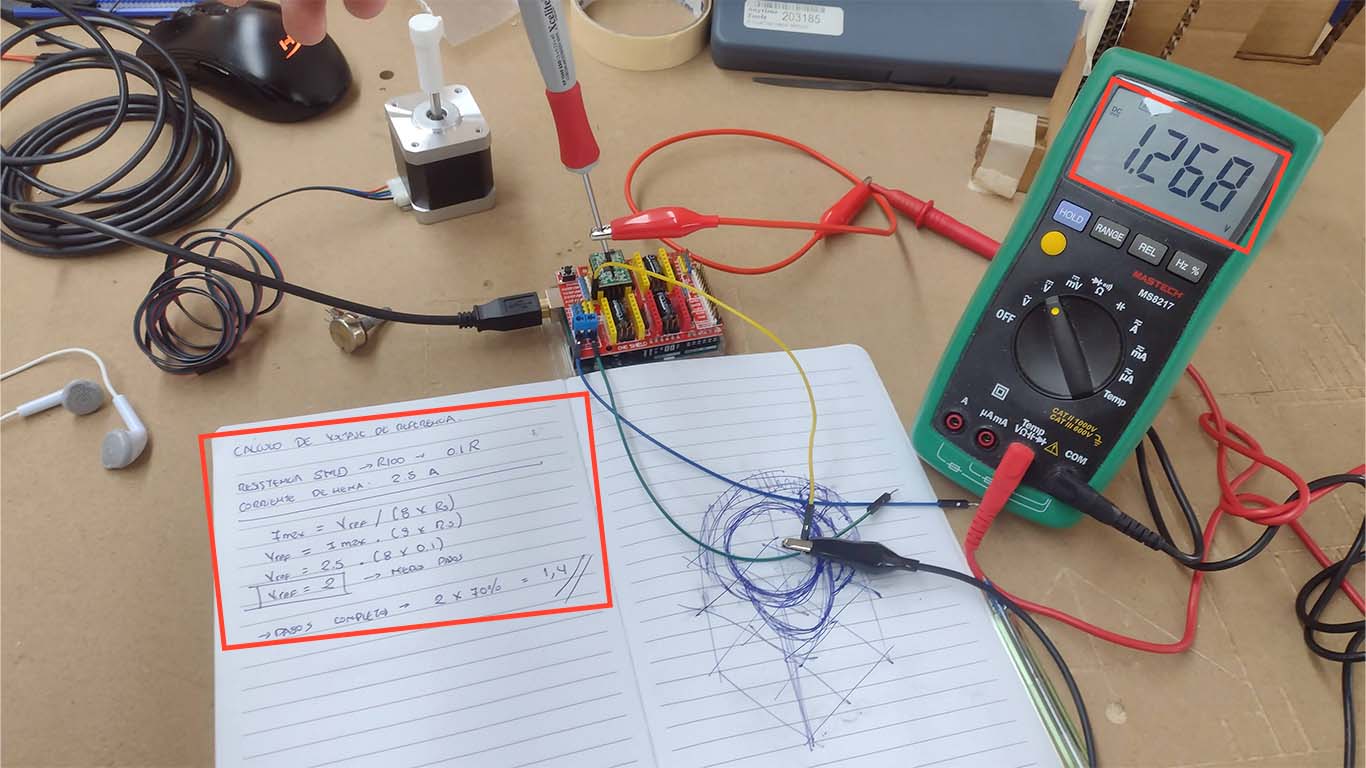
Before starting to connect, we have to take into account a calculation that is necessary to be able to operate the stepper motor with the A4899 DRIVER. We have to calculate the Reference Voltage, so here I show a calculation that I made taking into account my NEMA 17 STEPPING MOTOR 42BYGHW811 where I obtained a value of 1.4V. And with the help of the multimeter we can calibrate the current of the DRIVER A4899, in this case it only reached 1.268, so we leave it there and now it is ready to operate the stepper motor.
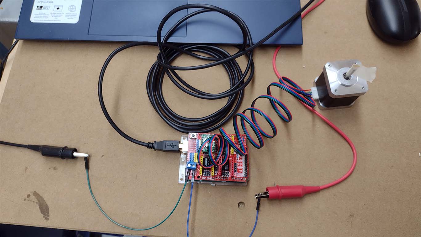
After calibrating the DRIVER A4899 and having all the connections ready to see the operation of the stepper motor, I went on to carry out a test with a basic programming that I leave here below and we can see that it works correctly.
                                #include AccelStepper.h

                                    // Define the connection pins for the A4988 driver on the CNC Shield
                                    #define X_STEP_PIN 2
                                    #define X_DIR_PIN 5
                                    #define X_ENABLE_PIN 8

                                    #define Y_STEP_PIN 3
                                    #define Y_DIR_PIN 6
                                    #define Y_ENABLE_PIN 8

                                    // Create AccelStepper instances for the X and Y axes
                                    AccelStepper stepperX(AccelStepper::DRIVER, X_STEP_PIN, X_DIR_PIN);
                                    AccelStepper stepperY(AccelStepper::DRIVER, Y_STEP_PIN, Y_DIR_PIN);

                                    void setup() {
                                      // Configure the driver enable pins
                                      pinMode(X_ENABLE_PIN, OUTPUT);
                                      pinMode(Y_ENABLE_PIN, OUTPUT);
                                      digitalWrite(X_ENABLE_PIN, LOW); // Enable the X driver (LOW to enable)
                                      digitalWrite(Y_ENABLE_PIN, LOW); // Enable the Y driver (LOW to enable)

                                      // Set maximum speed and acceleration
                                      stepperX.setMaxSpeed(1000);    // Maximum speed in steps per second
                                      stepperX.setAcceleration(500); // Acceleration in steps per second^2

                                      stepperY.setMaxSpeed(1000);    // Maximum speed in steps per second
                                      stepperY.setAcceleration(500); // Acceleration in steps per second^2

                                      // Set an initial position
                                      stepperX.setCurrentPosition(0);
                                      stepperY.setCurrentPosition(0);
                                    }

                                    void loop() {
                                      // Move the motor on the X axis to a new position
                                      stepperX.moveTo(200); // Move the motor to the position 200 steps

                                      // Move the motor on the Y axis to a new position
                                      stepperY.moveTo(200); // Move the motor to the position 200 steps

                                      // Execute the movement until the desired position is reached
                                      while (stepperX.distanceToGo() != 0 || stepperY.distanceToGo() != 0) {
                                        stepperX.run();
                                        stepperY.run();
                                      }

                                      // Wait for one second
                                      delay(1000);

                                      // Move the motor back to the initial position
                                      stepperX.moveTo(0);
                                      stepperY.moveTo(0);

                                      // Execute the movement until the desired position is reached
                                      while (stepperX.distanceToGo() != 0 || stepperY.distanceToGo() != 0) {
                                        stepperX.run();
                                        stepperY.run();
                                      }

                                      // Wait for one second
                                      delay(1000);
                                    }
After making the connection and programming it in ARDUINO IDE, we can see that the stepper motor has movement. Here is a video of what was developed:
STEPPER MOTOR + POTENTIOMETER
Then I remembered that I have to use a POTENTIOMETER to get the movement of my stepper motors so that they also work in sync. So, investigate different ways to drive 2 stepper motors with a single potentiometer, but let's remember to work in a spiral, so get it done with a single motor first. Here I leave a link of the POTENTIOMETER AND STEP MOTOR that I took as a reference to know the connection and programming.
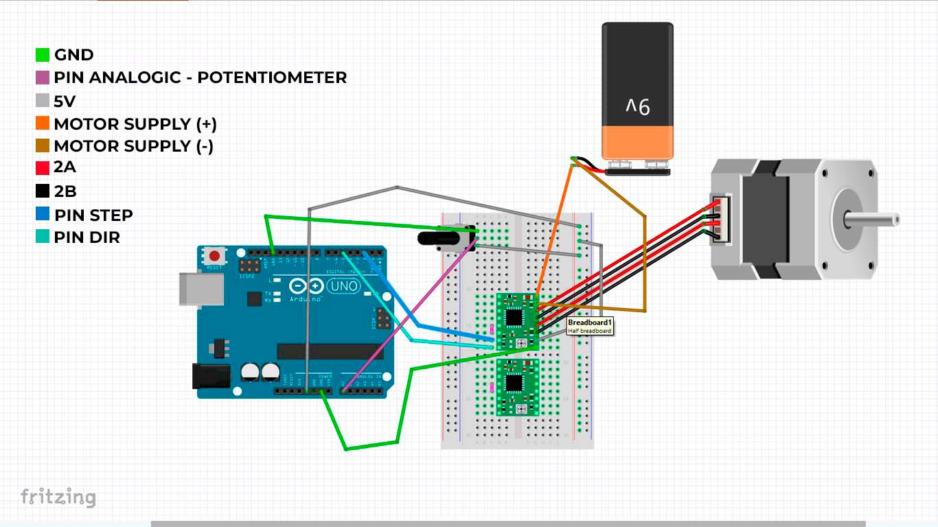
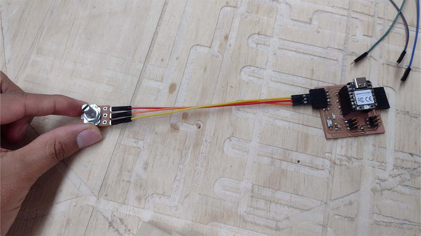
After understanding the connection of the reference, I went on to make the connections of my stepper motor with the potentiometer. First I made a diagram in FRITZING to understand the connectivity and then I started developing on a PROTOBOARD. Here is a screenshot of the fritzing and the connection I made.
After checking the connection that everything is fine according to the reference and also supervising that each cable is connected in the indicated place, I went on to program it, here is the programming code for the test.
                                // defines pins
                                #define stepPin 2
                                #define dirPin 5

                                const int stepsPerRevolution = 200; // Number of steps per revolution (adjust according to your motor)
                                const float degreesPerStep = 360.0 / stepsPerRevolution; // Degrees per step

                                int currentStep = 0; // Current motor position in steps
                                int targetStep = 0;  // Target motor position in steps

                                void setup() {
                                // Sets the two pins as Outputs
                                pinMode(stepPin, OUTPUT);
                                pinMode(dirPin, OUTPUT);
                                Serial.begin(9600); // For debugging
                                }

                                void loop() {
                                // Read the potentiometer value
                                int potValue = analogRead(A0);

                                // Map the potentiometer value to an angle between 0 and 180 degrees
                                int targetAngle = map(potValue, 0, 1023, 0, 180);

                                // Calculate the target step position
                                targetStep = targetAngle / degreesPerStep;

                                // Ensure the targetStep is within bounds (0 to 180 degrees)
                                targetStep = constrain(targetStep, 0, 180 / degreesPerStep);

                                // Move the motor to the target position
                                moveToPosition(targetStep);

                                // Print debug information
                                Serial.print("Potentiometer Value: ");
                                Serial.print(potValue);
                                Serial.print(" | Target Angle: ");
                                Serial.print(targetAngle);
                                Serial.print(" | Current Step: ");
                                Serial.print(currentStep);
                                Serial.print(" | Target Step: ");
                                Serial.println(targetStep);
                                }

                                void moveToPosition(int targetStep) {
                                if (targetStep > currentStep) {
                                    // Move forward
                                    digitalWrite(dirPin, HIGH);
                                    while (currentStep < targetStep) {
                                    digitalWrite(stepPin, HIGH);
                                    delayMicroseconds(1000); // Adjust the delay according to the desired speed
                                    digitalWrite(stepPin, LOW);
                                    delayMicroseconds(1000); // Adjust the delay according to the desired speed
                                    currentStep++;
                                    }
                                } else if (targetStep < currentStep) {
                                    // Move backward
                                    digitalWrite(dirPin, LOW);
                                    while (currentStep > targetStep) {
                                    digitalWrite(stepPin, HIGH);
                                    delayMicroseconds(1000); // Adjust the delay according to the desired speed
                                    digitalWrite(stepPin, LOW);
                                    delayMicroseconds(1000); // Adjust the delay according to the desired speed
                                    currentStep--;
                                    }
                                }
                                }
After programming we can see in the following video that the connection and programming of the motor works.
2 STEPPER MOTORS + POTENTIOMETER
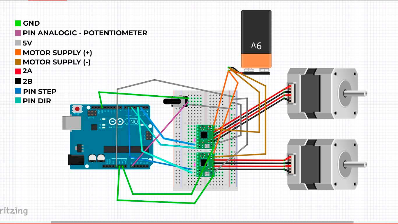
After developing the tests mentioned above, I am now going to perform the synchronization, programming and connectivity of 2 stepper motors with a single potentiometer. First I made a diagram in FRITZING to know the connection, at first I didn't know it would work but here is my process.
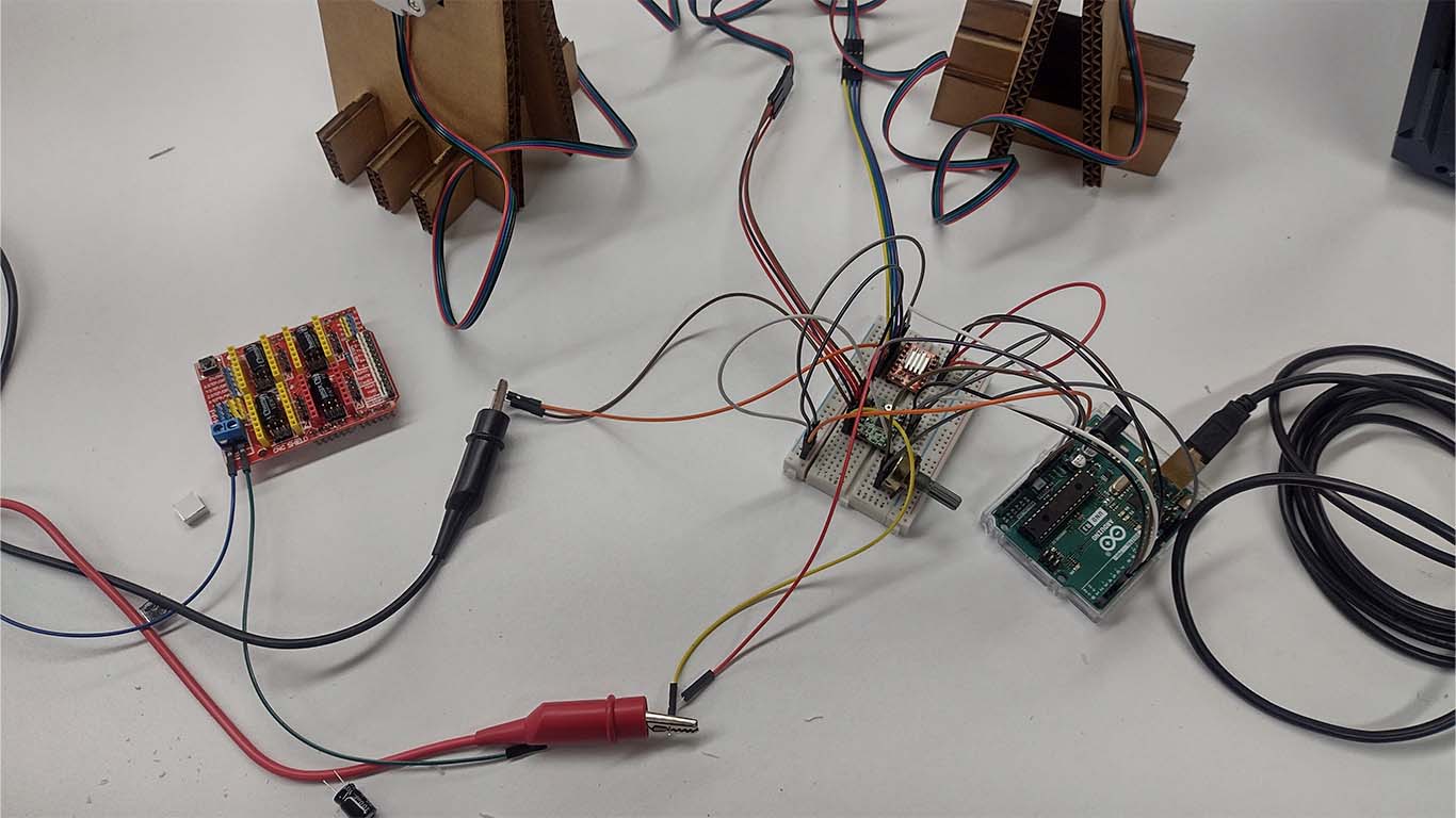
After making all the connections, I went on to make my connection on my PROTOBOARD that I am using for testing and operation of the motors. It seems like a whole spider web but I understand it haha, sorry but it was one of the quickest ways to know if it would work.
After checking that all the cables are correctly connected according to the previous test and I wanted to know at that moment if it could work like this, I programmed it with the following code:
                                // defines pins for Motor 1
                                #define stepPin1 2
                                #define dirPin1 5

                                // defines pins for Motor 2
                                #define stepPin2 3
                                #define dirPin2 6

                                const int stepsPerRevolution = 200; // Number of steps per revolution (adjust according to your motor)
                                const float degreesPerStep = 360.0 / stepsPerRevolution; // Degrees per step

                                int currentStep1 = 0; // Current position of motor 1 in steps
                                int currentStep2 = 0; // Current position of motor 2 in steps

                                void setup() {
                                // Sets the two pins as Outputs for Motor 1
                                pinMode(stepPin1, OUTPUT);
                                pinMode(dirPin1, OUTPUT);

                                // Sets the two pins as Outputs for Motor 2
                                pinMode(stepPin2, OUTPUT);
                                pinMode(dirPin2, OUTPUT);

                                Serial.begin(9600); // For debugging
                                }

                                void loop() {
                                // Read the potentiometer value
                                int potValue = analogRead(A0);

                                // Map the potentiometer value to an angle between 0 and 180 degrees
                                int targetAngle = map(potValue, 0, 1023, 0, 180);

                                // Calculate the target step position
                                int targetStep = targetAngle / degreesPerStep;

                                // Ensure the targetStep is within bounds (0 to 180 degrees)
                                targetStep = constrain(targetStep, 0, 180 / degreesPerStep);

                                // Move both motors to the target position
                                moveToPosition(targetStep);

                                // Print debug information
                                Serial.print("Potentiometer Value: ");
                                Serial.print(potValue);
                                Serial.print(" | Target Angle: ");
                                Serial.print(targetAngle);
                                Serial.print(" | Current Step 1: ");
                                Serial.print(currentStep1);
                                Serial.print(" | Current Step 2: ");
                                Serial.print(currentStep2);
                                Serial.print(" | Target Step: ");
                                Serial.println(targetStep);
                                }

                                void moveToPosition(int targetStep) {
                                moveMotor(stepPin1, dirPin1, currentStep1, targetStep);
                                moveMotor(stepPin2, dirPin2, currentStep2, targetStep);
                                }

                                void moveMotor(int stepPin, int dirPin, int ¤tStep, int targetStep) {
                                if (targetStep > currentStep) {
                                    // Move forward
                                    digitalWrite(dirPin, HIGH);
                                    while (currentStep < targetStep) {
                                    digitalWrite(stepPin, HIGH);
                                    delayMicroseconds(1000); // Adjust the delay according to the desired speed
                                    digitalWrite(stepPin, LOW);
                                    delayMicroseconds(1000); // Adjust the delay according to the desired speed
                                    currentStep++;
                                    }
                                } else if (targetStep < currentStep) {
                                    // Move backward
                                    digitalWrite(dirPin, LOW);
                                    while (currentStep > targetStep) {
                                    digitalWrite(stepPin, HIGH);
                                    delayMicroseconds(1000); // Adjust the delay according to the desired speed
                                    digitalWrite(stepPin, LOW);
                                    delayMicroseconds(1000); // Adjust the delay according to the desired speed
                                    currentStep--;
                                    }
                                }
                                }
Finally, I gave them all a final check and it worked, I was able to make the potentiometer control both stepper motors, I still need to synchronize but esperial after spiral it could be achieved. Here is a video of what was developed:
NEOPIXEL SYSTEM
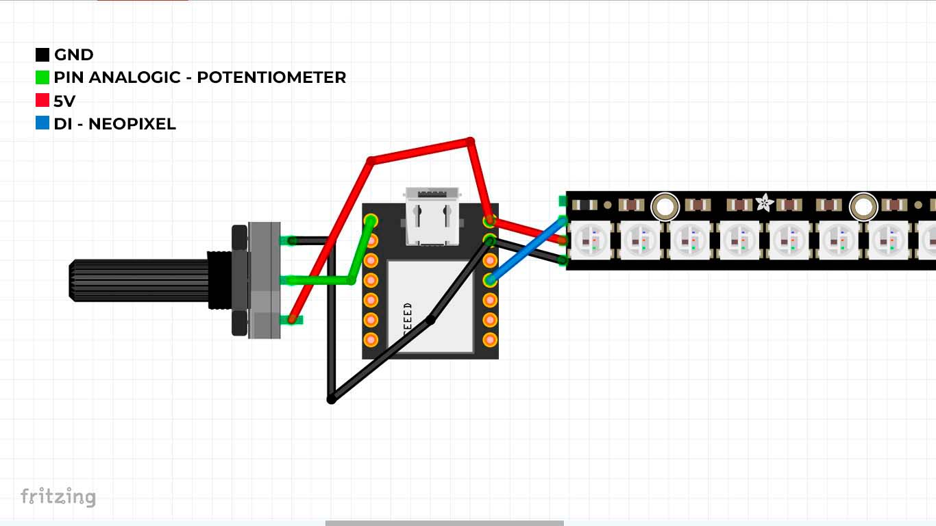
For the neopixel system, similar to what was done with the stepper motors, I will make a simple connection of the neopixel to a board developed in WEEK 13 that will help me connect both the POTENTIOMETER and the NEOPIXEL and the idea is that according to the location The potentiometer can turn the NEOPIXELS on and off. Here the development process, first I made my connection diagram in FRITZING and for this case I will use the XIAO RP2040.
After making my schematic diagram of my connection, I begin to connect the POTENTIOMETER pins on the developed board where the XIAO RP2040 is located.
Then I attached my strip of NEOPIXEL that I had already glued to the arch of my final project to see how it would look and how it would work. And now to do the programming to see if it works correctly.

                                #include Adafruit_NeoPixel.h

                                    // Neopixel strip configuration
                                    #define NUM_PIXELS 27  // Number of LEDs in the strip
                                    #define PIXEL_PIN 3    // Pin where the Neopixel strip is connected

                                    // Potentiometer configuration
                                    #define POTENTIOMETER_PIN 26  // Analog pin where the potentiometer is connected

                                    // Create Neopixel object
                                    Adafruit_NeoPixel pixels(NUM_PIXELS, PIXEL_PIN, NEO_GRB + NEO_KHZ800);

                                    void setup() {
                                      // Initialize the Neopixel object
                                      pixels.begin();
                                      pixels.show(); // Initialize all LEDs to off
                                    }

                                    void loop() {
                                      // Read the potentiometer position
                                      int potValue = analogRead(POTENTIOMETER_PIN);

                                      // Map the potentiometer value to the range of 0 to NUM_PIXELS - 1
                                      int ledIndex = map(potValue, 0, 1023, 0, NUM_PIXELS - 1);

                                      // Turn off all LEDs
                                      for (int i = 0; i < NUM_PIXELS; i++) {
                                        pixels.setPixelColor(i, pixels.Color(0, 0, 0));  // Turn off LED
                                      }

                                      // Turn on only the corresponding LED
                                      pixels.setPixelColor(ledIndex, pixels.Color(255, 255, 255));  // White color

                                      // Update the LED strip
                                      pixels.show();

                                      // Small delay to avoid reading too frequently
                                      delay(100);
                                    }
After programming, I first tested the entire neopixel strip to see if each one of them was working correctly. From this, I added the potentiometer to make movement according to its position and to turn neopixels on and off.
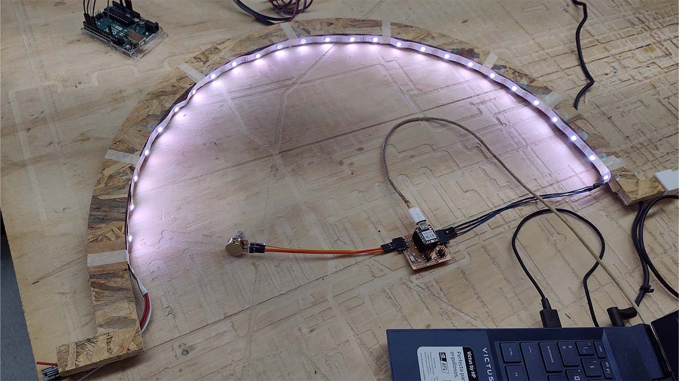
Finally, here is a video of how I want the neopixel to be able to work according to the position of the potentiometer and to work in sets.
SUPPORT AND FEEDBACK
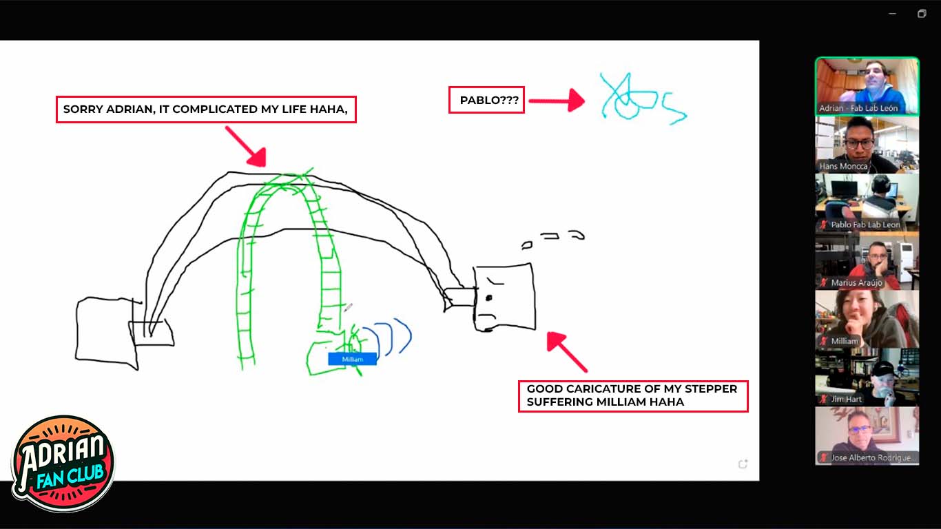
GLOBAL OPEN TIME
In this week's Global Open Time, teacher Adrian explained what is sought in the assignment and more was said about the final projects that we have to develop because time is running out on us. Here is a screenshot of my critique of my final project where we can see the ideas that everyone present recommended to me and haha I found the moment very funny when Milliam started making caricatures of my stepper motors that were struggling to load my final project. One more week of talking and learning from wonderful people. Thank you all, for now I'm struggling with my final project but the Global Open Time is very fun.
DESIGNING MY FINAL PROJECT BOARD
COMPONENT LIST
To start creating my integration system, I will design my board for my final project since I have all the components that I will need and maybe I will change one or another but not the majority because this week I took advantage of it to do all of this. Here is the list of electronic components that I will need.
| COMPONENTS | QUANTITY | UNITS | PRODUCT CODE | PRICE | TOTAL |
|---|---|---|---|---|---|
| XIAO RP2040 | 1 | unit | RP2040 | $9.90 | $9.90 |
| STEPPER MOTOR NEMA 17 | 3 | unit | 42BYGHW811 | $16.17 | $48.51 |
| POTENTIOMETER B50K | 3 | unit | 987-1714-ND | $1.83 | $5.49 |
| NEOPIXEL | 1 | ml | WS2812B | $13.34 | $13.34 |
| ADAPTER 12V | 1 | unit | 1225 | $4.80 | $4.80 |
| DRIVER A4899 | 1 | unit | A4899 | $2.27 | $2.27 |
| DRIVER DRV8825 | 2 | unit | DRV8825 | $3.40 | $6.80 |
| TOTAL | $91.11 |
DESIGN MY BOARD
For my final project board design, I recapped what was shown above so I could connect all the components I will need. From this, I began to connect in the FRITZING program since the connection is easier and allows us to see if we need something. Here is my diagram of my integration system from my final project.
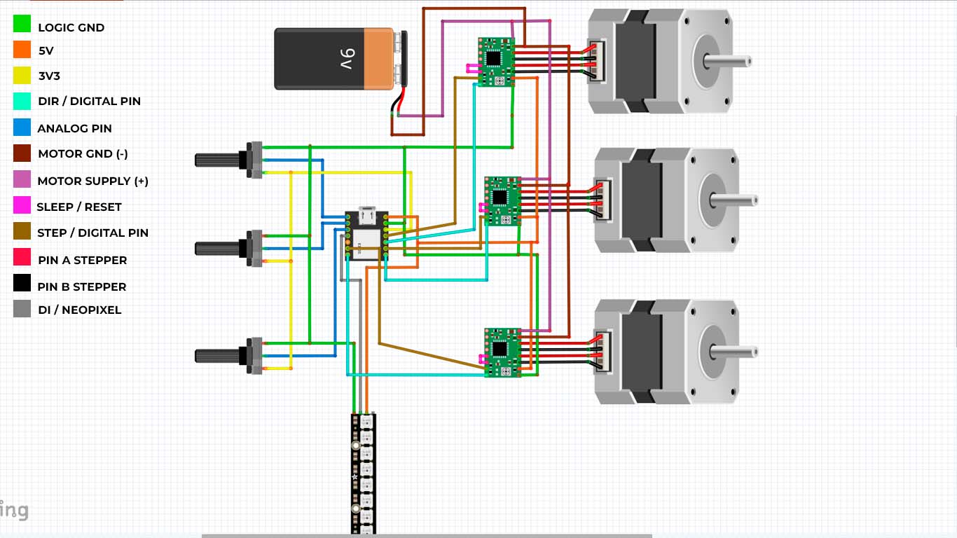
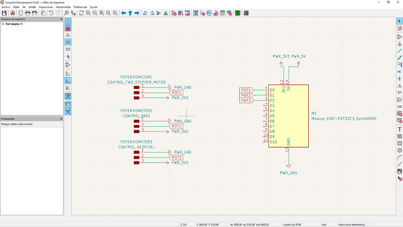
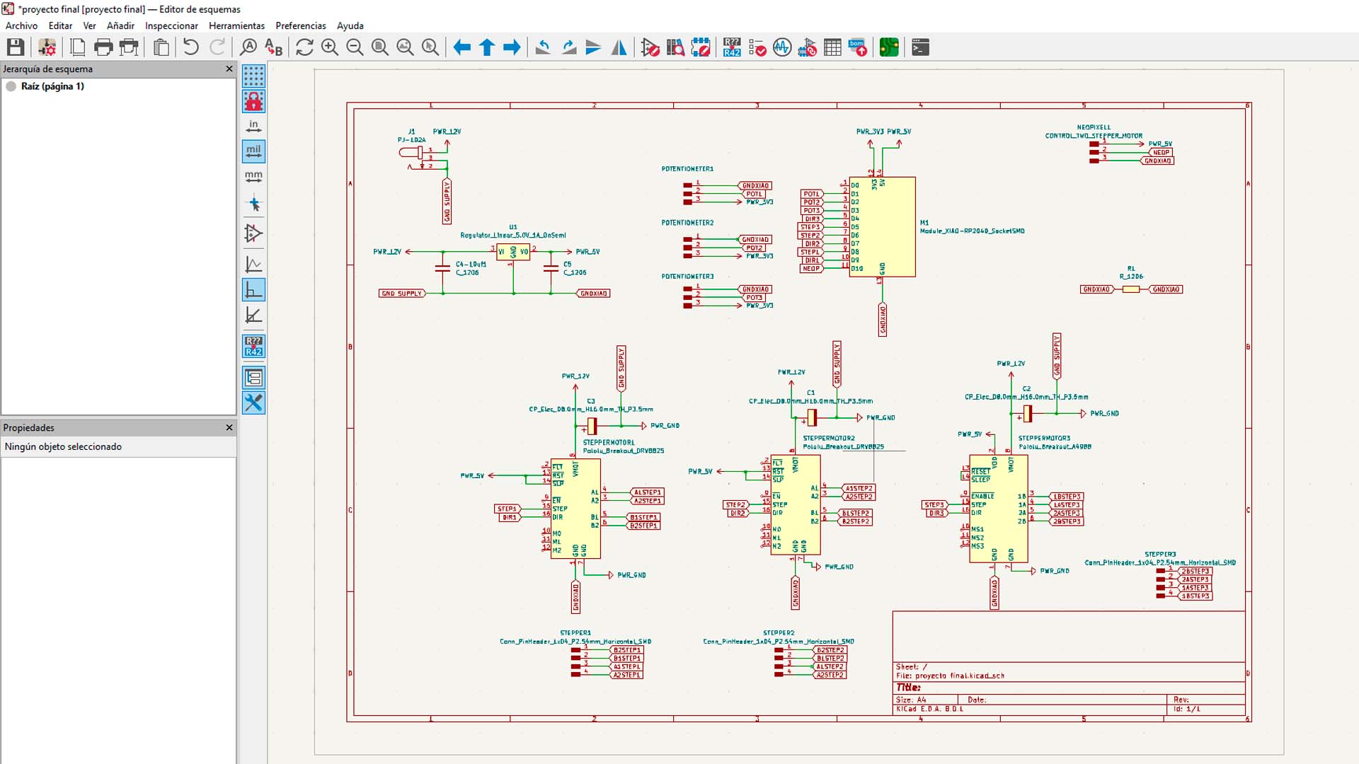
After completing the connectivity and checking that everything is correct, we will move on to the KICAD program to be able to develop the design of my board for the final project. First I started by making the connectivity of the 3 potentiometers that I will have. One of them will control 2 step motors, the other will control the base step motor and finally the last potentiometer will be used to turn on and operate the neopixel.
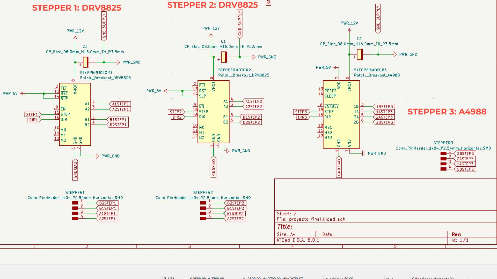
Then I started working with the connection of the drivers that I have to use to move the stepper motors that I have. For my final project I could only get 2 DRV8825 drivers and 1 A4988 driver, so I tried to accommodate my board with these two types of drivers. Before starting to make the connections that I would need, we have to read the datasheets of each one to know what type of components apart from the drivers we need for their correct operation. Therefore, add components such as capacitors that are necessary for these components to function correctly.
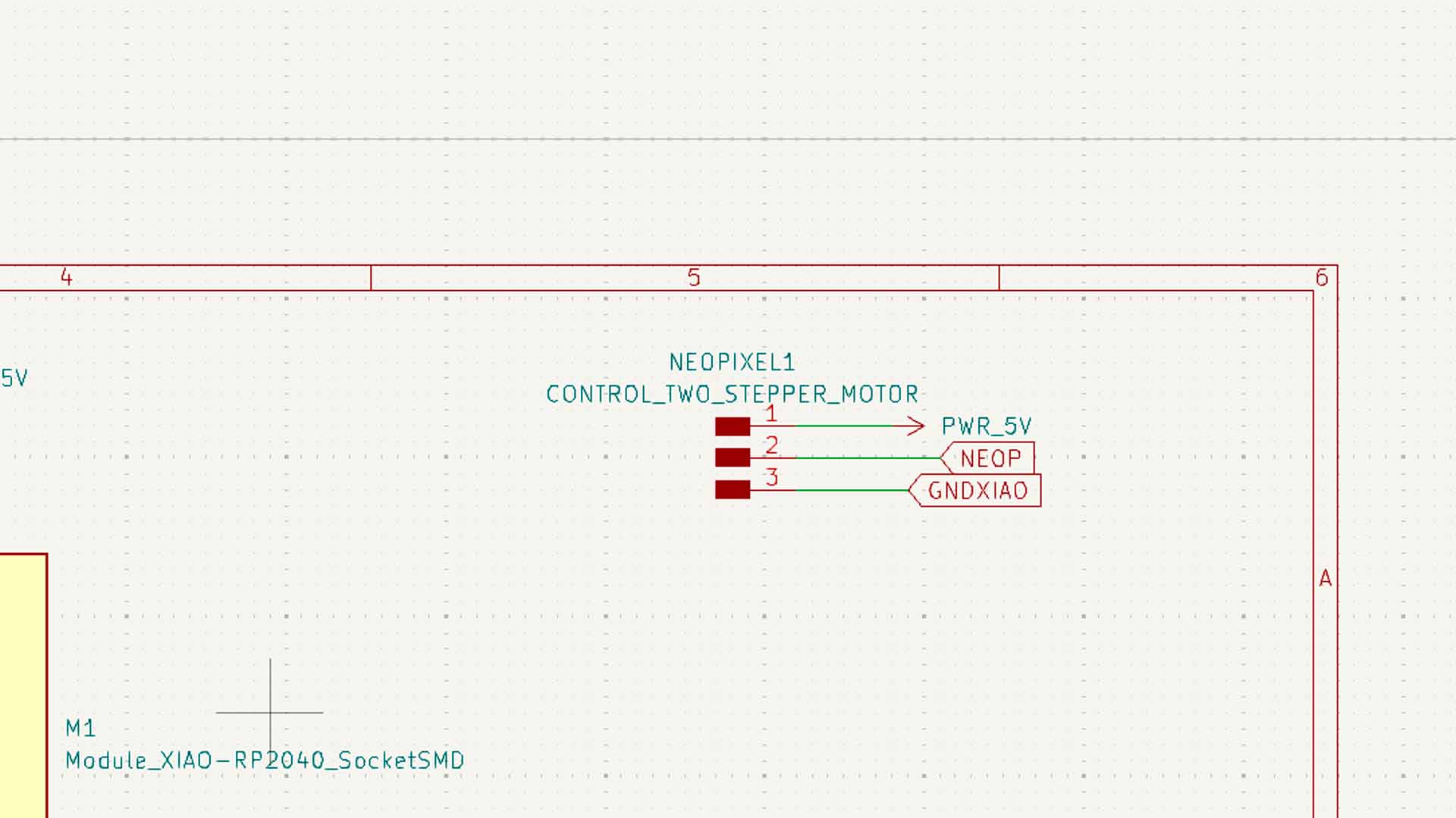
On the other hand, I also added the connector to connect my neopixels that will also be part of the project.
Finally, I started working on the connections of how my entire board was going to be powered. In this case I will use a DC SMD PLUG that will be powered by 12V and will power my entire board according to the calculation of all my components. And also, I will use a 5V voltage regulator to power my XIAO RP2040 and my neopixels that work with that voltage and avoid burning them.
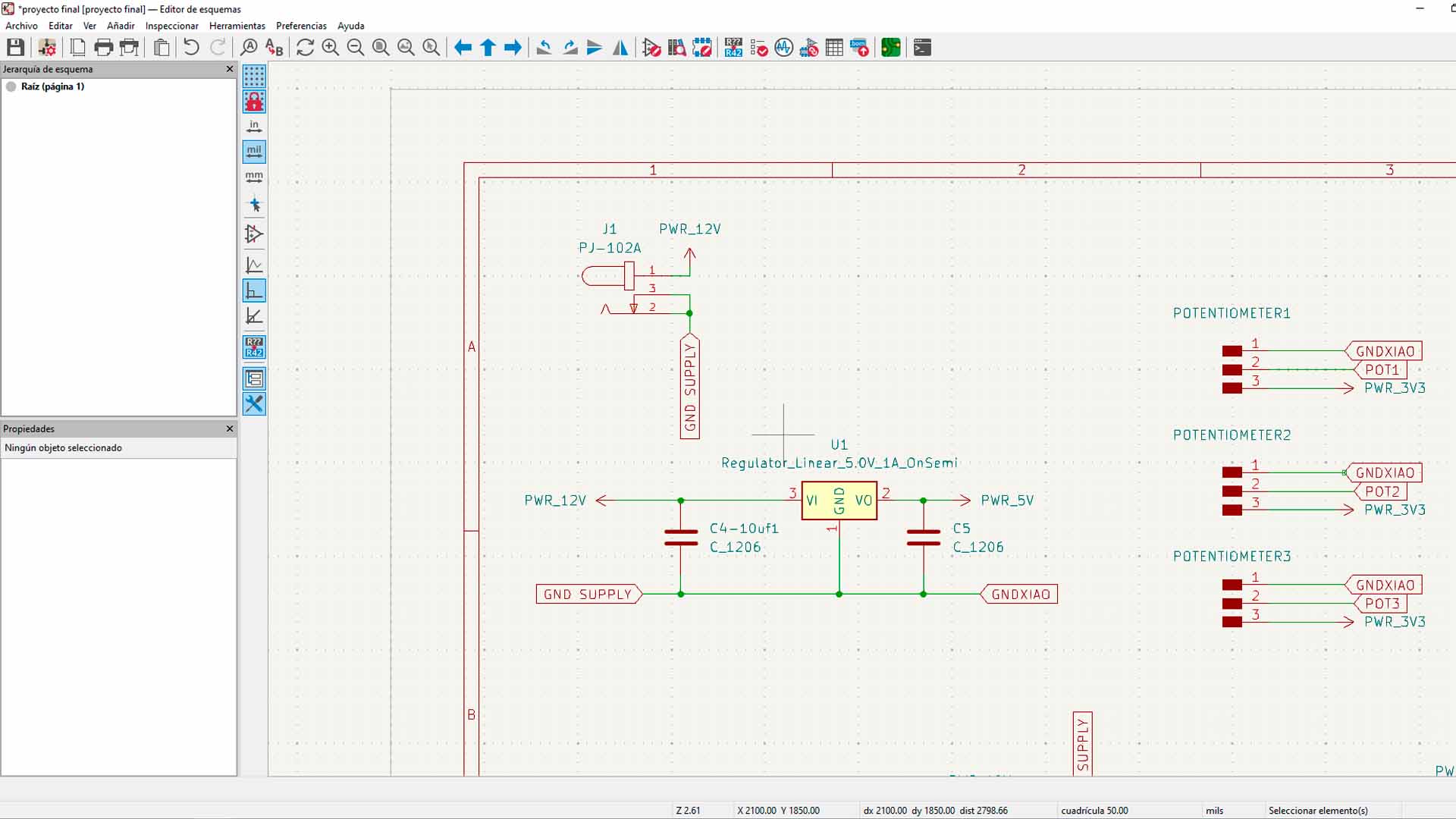
Here I leave a screenshot of all my schematic work on my board for my final project. Now we will move on to the design of the board.
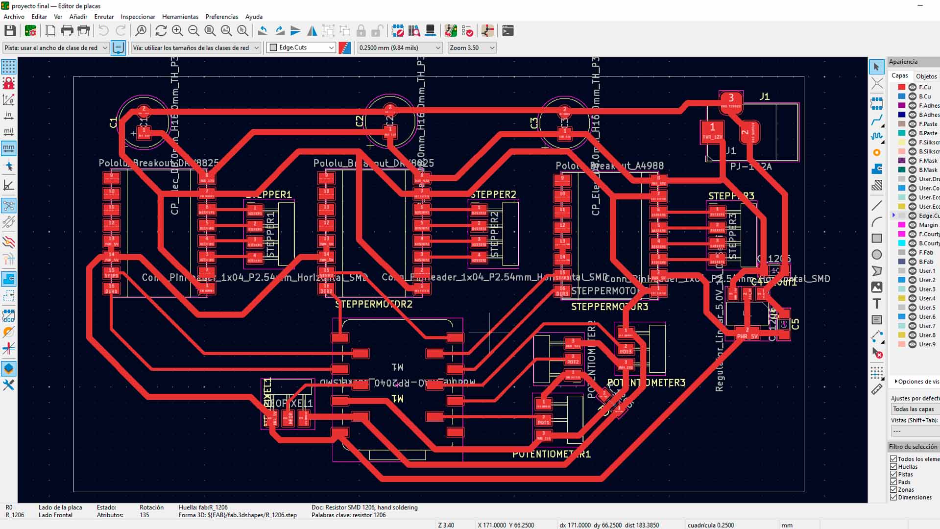
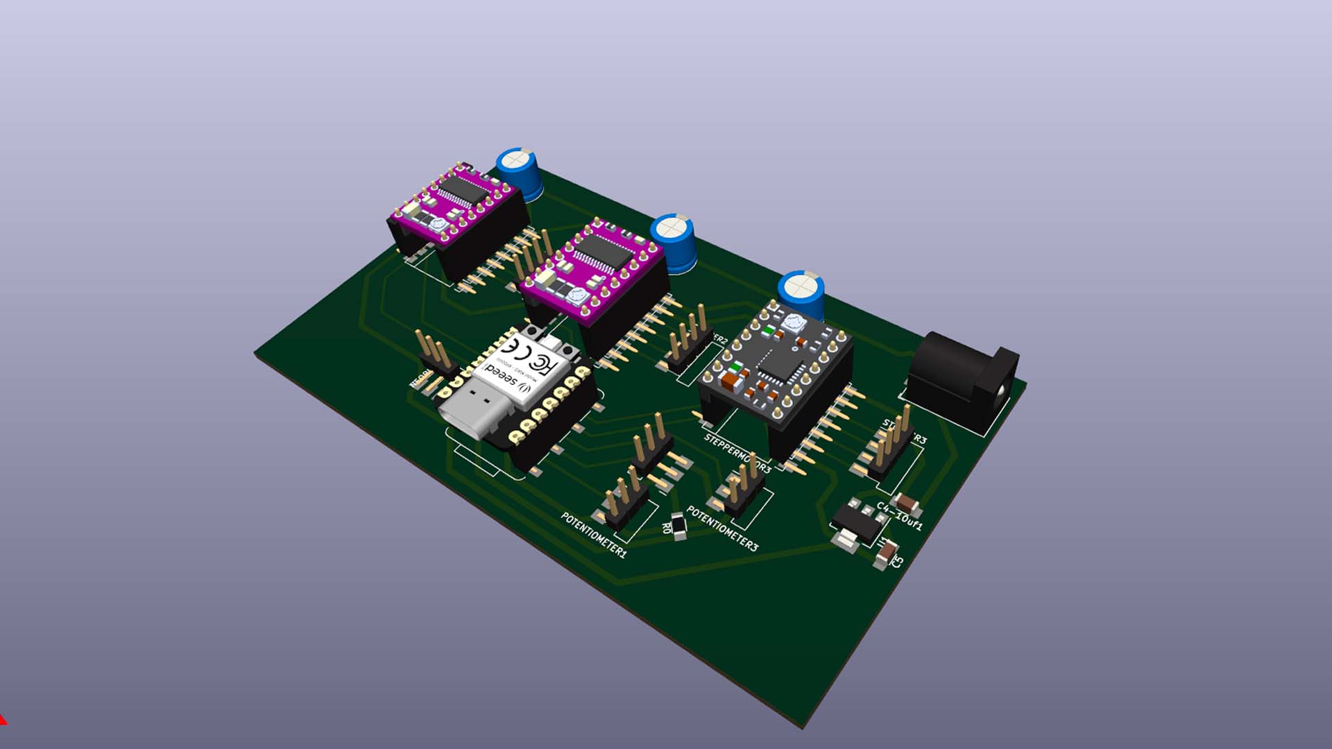
There were many components that I did not know how to arrange, a tip that I can leave you is that everything starts from the microcontroller and from there you can distribute the other components to avoid complications and they can generate a whole "spider web" which is not the idea. Here is a design of my final plate ready for milling and welding.
MILLING AND SOLDERING
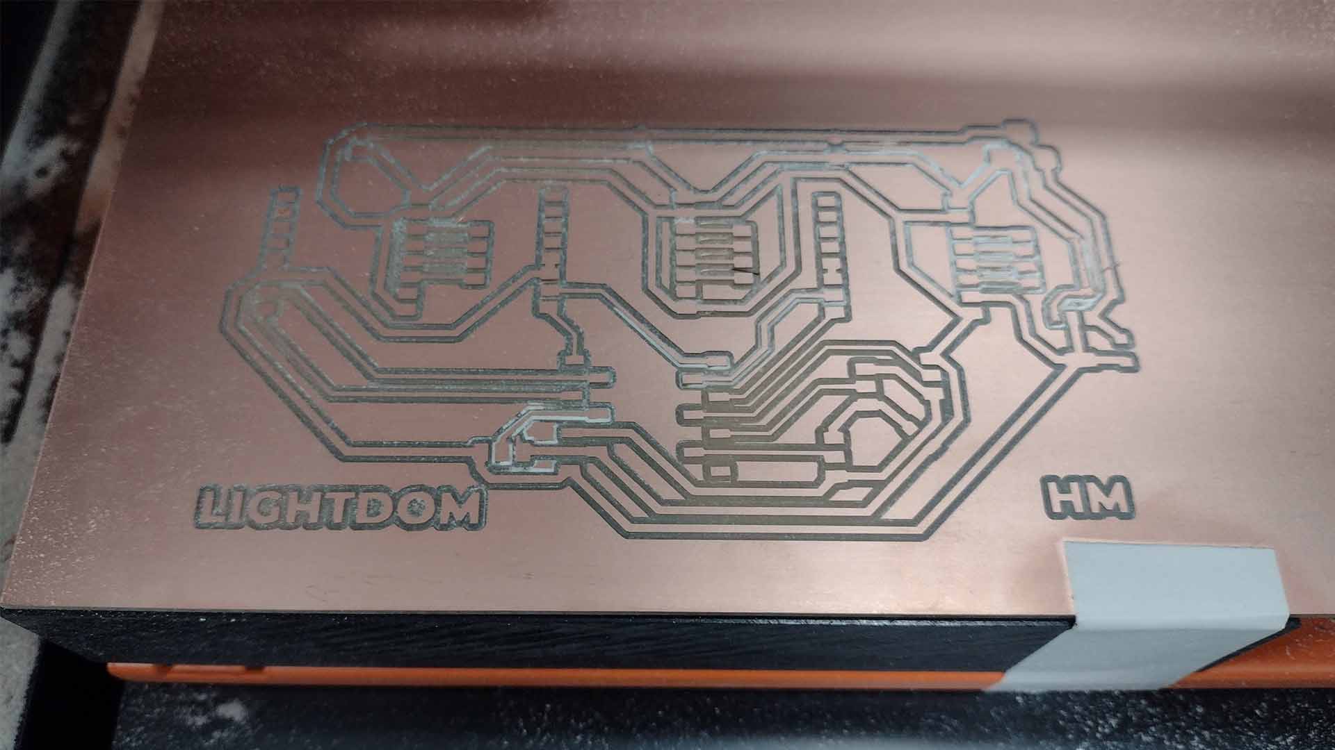
After obtaining the design of my board in KICAD and checking that all the connections are correctly made. I move on to milling my board on the ROLAND SRM 20 MONOFAB, where we first mill the tracks with the 1/64 milling cutter and then move on to cutting the edge with the 1/32 milling cutter.
To solder, I started by placing all the connectors, small components such as resistors, regulators and capacitors that seemed more difficult to me since there were several of them and it was a bit complicated for me to solder them.
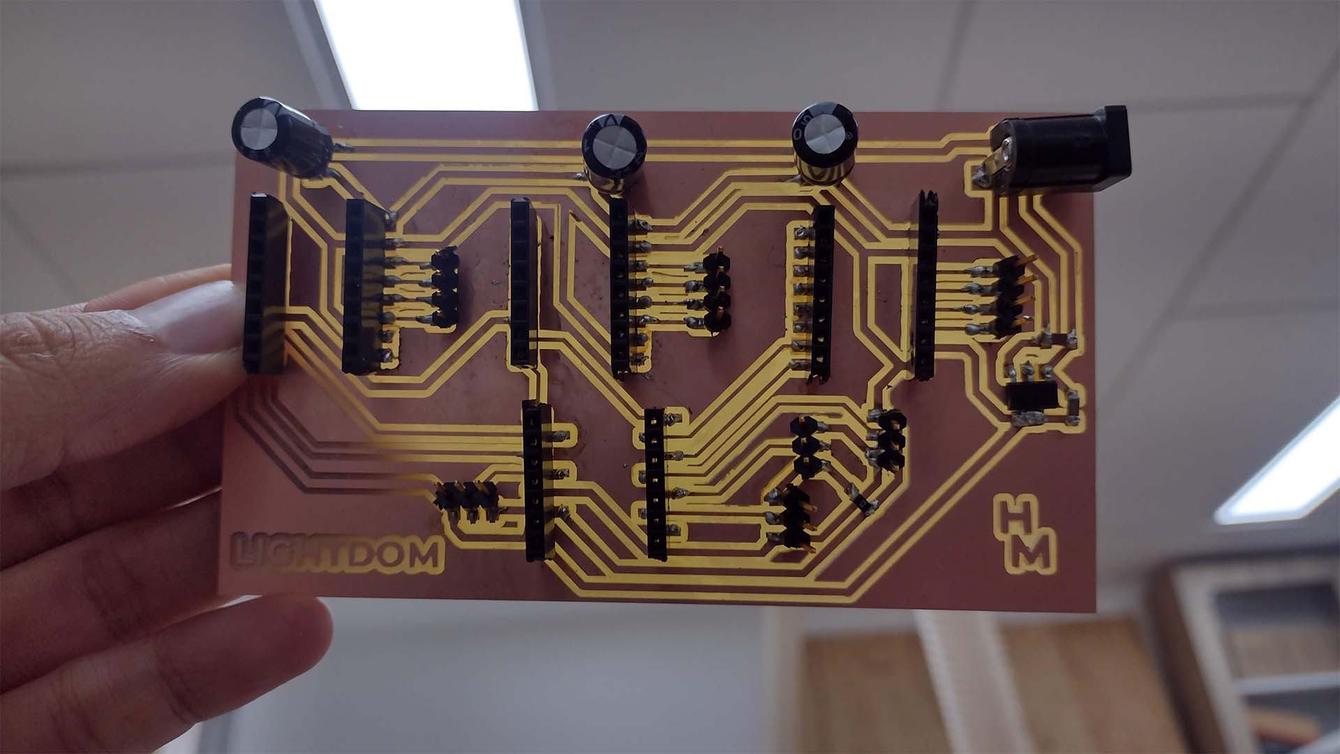
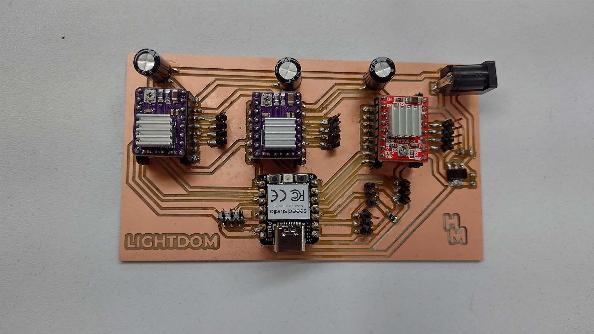
Finally, after soldering and checking continuity with a multimeter. I proceed to place the drivers and the microcontroller that this time I will use the XIAO RP2040 and it would be ready to use.
DESIGN A CASE
DESIGN MY BOARD
This week of system integration was an assignment that we had to see how all the components and cables look integrated. Therefore, once I had the design part and knew the final measurement of my board from the final project, I was able to make a case where I could place my board and the potentiometers that were going to move my project. Therefore I designed a 3D printed case to be able to place everything and obviously also connect with my stepper motors.
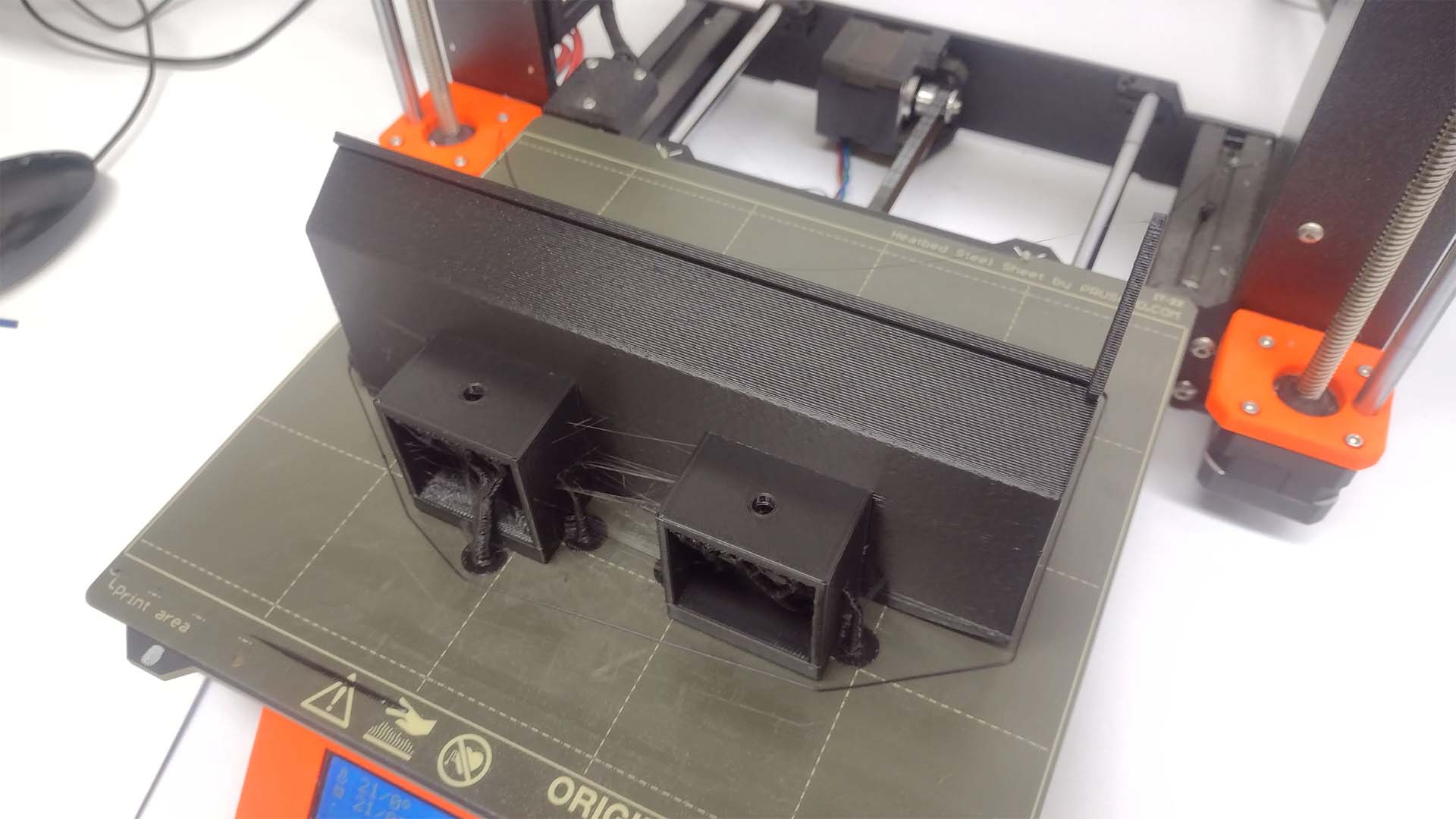
First I had my base 3D printed where I am going to place my board and where it will connect to the cables of my motors.
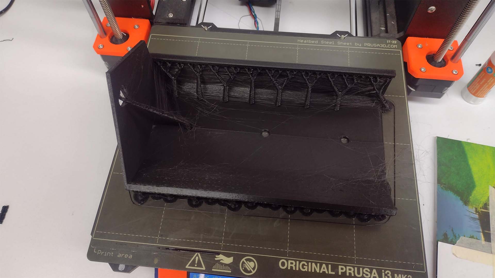
Then he ordered the cover that covers my plate to be 3D printed and also where the potentiometers were going to be placed so that the user can operate my device.
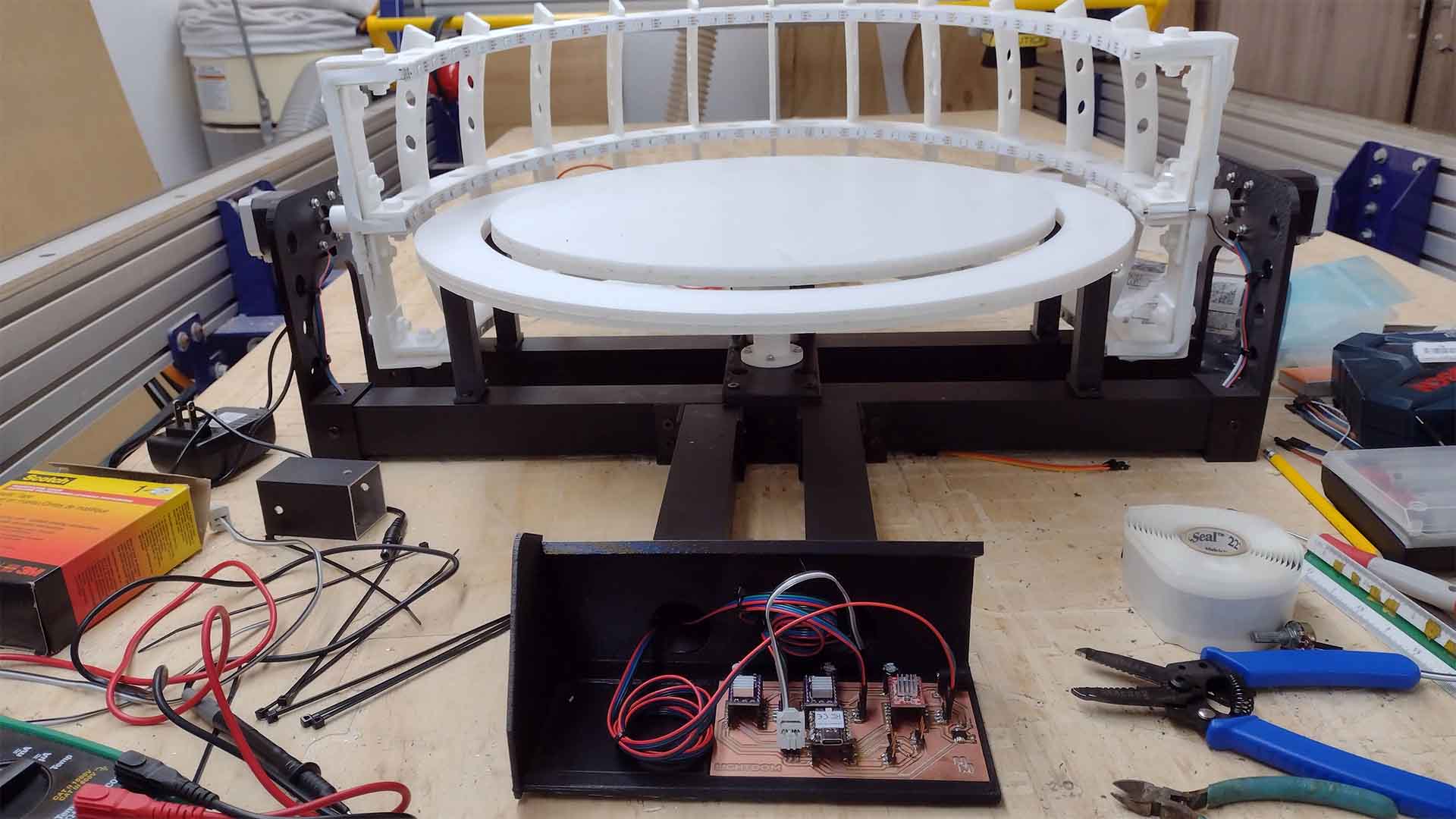
Here is a photograph of where all my circuits and my developed board were going to be located. First I began to connect all the cables of my motors that were immersed within the aluminum of the structure of my device and connected to my board.
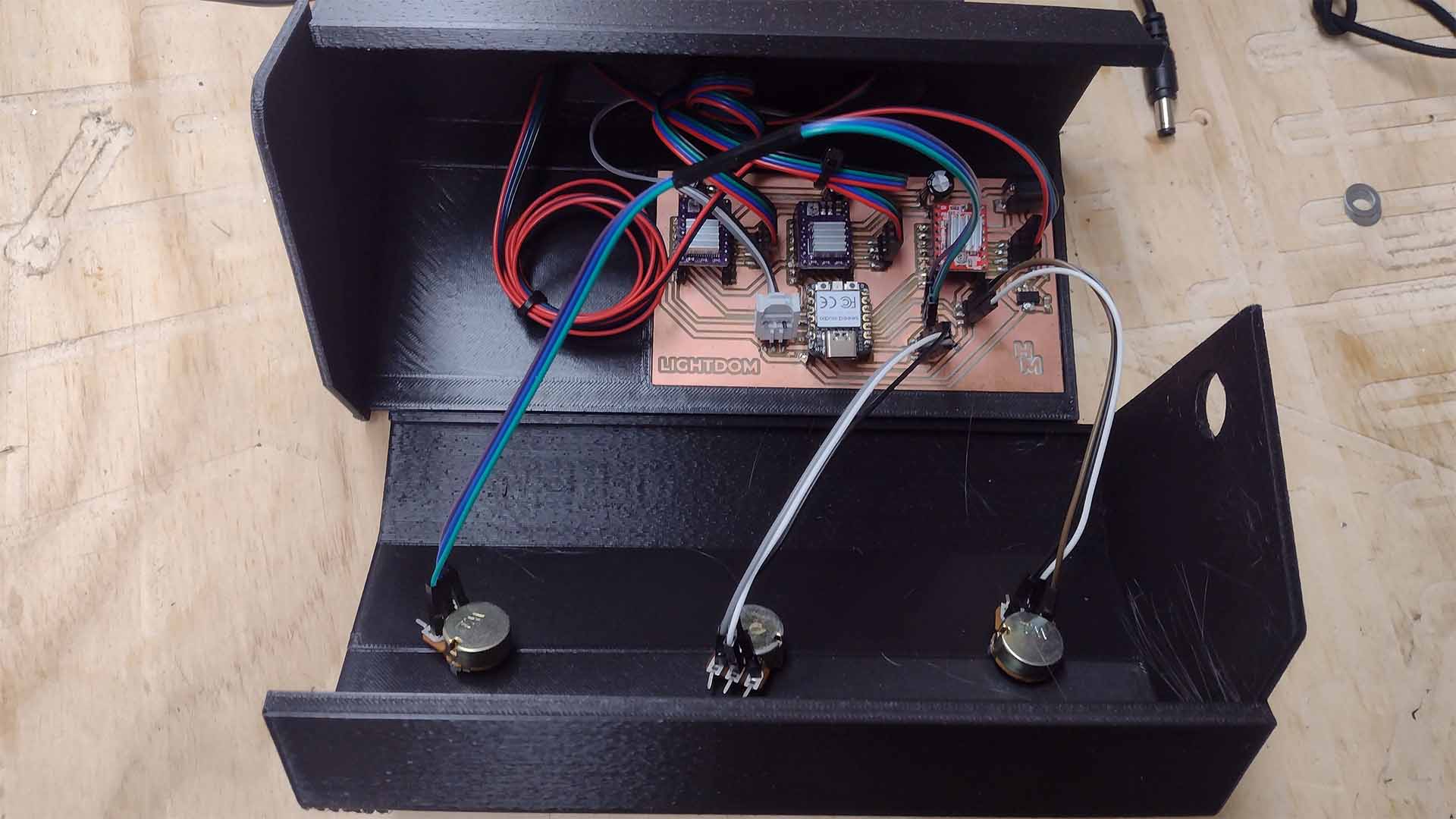
After making the first connection, I went on to connect my potentiometers that were going to be on the front of my device and these were also going to be connected to my board. Here is a photograph of my connections of my potentiometers and ready to use them.
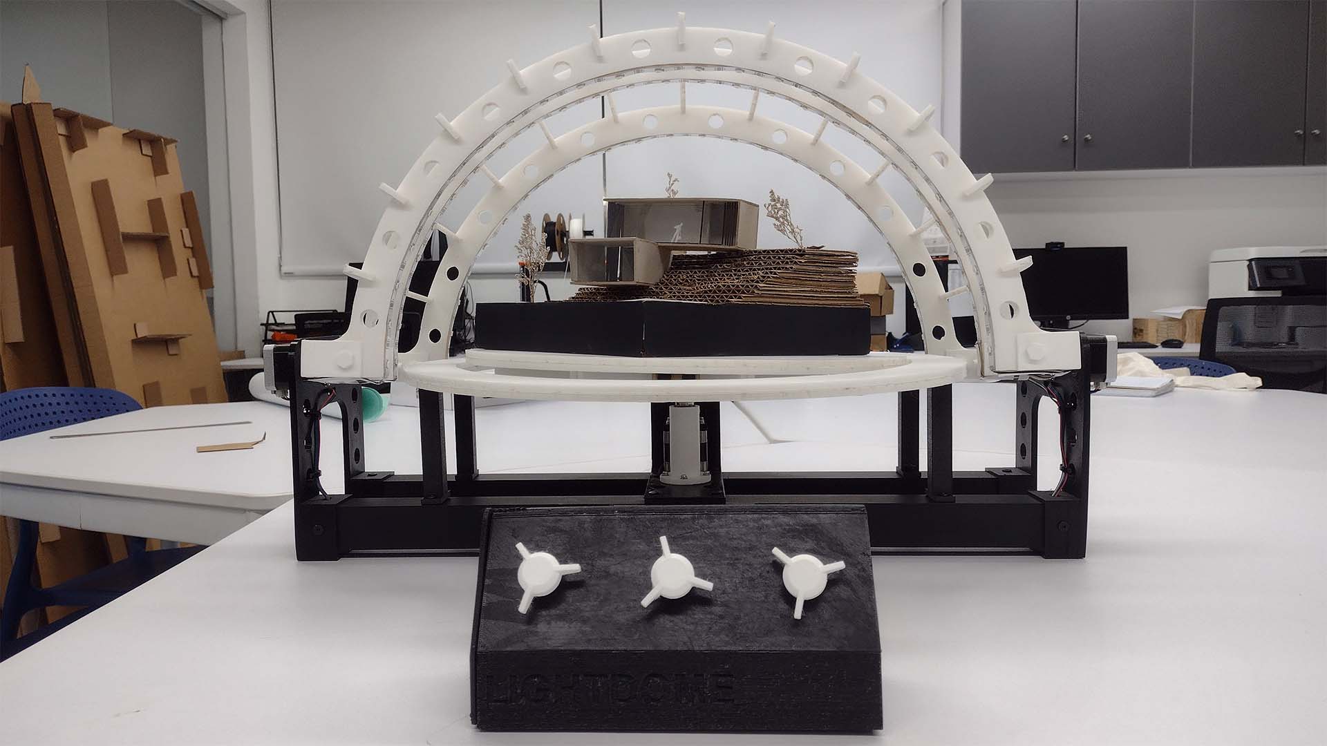
Finally, after a review of all the connections of my components, I went on to cover it with the cover that I designed for my case and also added some buttons inspired by the button that the Prusas have for handling and here is a screenshot of the result. I liked it because you don't see any cables and my entire integration system looks very clean. I am proud of what has been achieved.
CONCLUSIONS
This week I started making my models for my final project and the truth is that working in a spiral shape helped me a lot. Now I understand the methodology much better and also thanks to teacher Adrian Torres who is always supporting me. On the other hand, it is important to know the components or subsystems that we will have in our project to achieve an entire integrated system. In my case, working in the way that is documented helped me a lot because I understood many things and it makes it easier to take into account when making all the connection and operation of the final project. One more week of learning.
FINAL PROJECT
FIRST SPIRAL
From week 16 I started working on my final FAB ACADEMY project. I had had ideas, criticisms and talks about my project the previous weeks but I had not presented much progress since it was complicated with the work and tasks we had to do for weeks. Therefore, during this week I just started my final work, where thanks to the GLOBAL OPEN TIME recommendations, I had to work in spiral and parallel the processes that I was going to need, such as laser cutting, 3D printing and electronic design.
Therefore, for this week I wanted to start with my first spiral that I also explain on the PROJECT DEVELOPMENT page of each process used. The idea was to work in a spiral and parallel with each process to advance my final project and this because I was going to gain time for the final delivery if I did not work with this methodology and be constant.
The objective of my first spiral was to take my first steps in the design and development of my final project such as laser cutting, 3D printing and electronic design. I worked on all of this in parallel with the 3D design, changing and updating according to the errors I had.
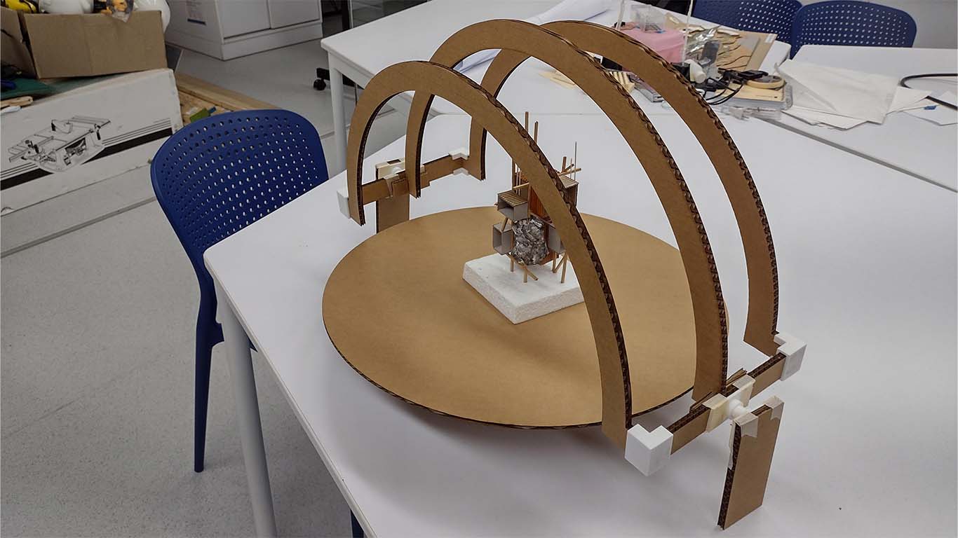
LASER CUTTING
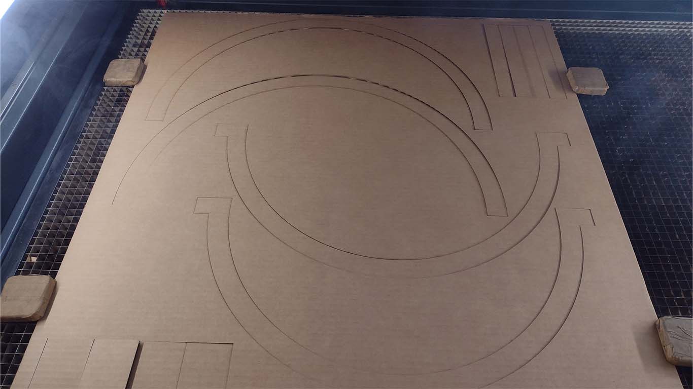
For the laser cutting process, I began by developing a model to see the size, complexities and needs that I would have to carry out my final project. Therefore, I made it on cardboard to speed up the cutting and the process, where I put together my model to give me an idea of the work. Here are some photographs of the process and what was achieved with the laser cutting for my first spiral.
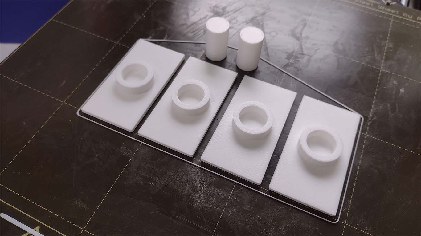
3D PRINTING
On the other hand, I started with the development of my 3D pieces where I wanted to make all the accessories and the movement axis with 3D printing. The idea for the first spiral was to understand how the axes and pieces were going to be developed in design. For this occasion I thought that the structure could be nestable, but I realized that it was very easy to disassemble, but with this process I was able to understand what way I was going to assemble the entire structure with the 3D pieces.
In the following video I make a simulation of how my device was going to work manually, to know the limitations it had and what parts I had to work on to send it to 3D printing, for example the most complicated challenge was achieving the axis since I had to find the right design to make it work.
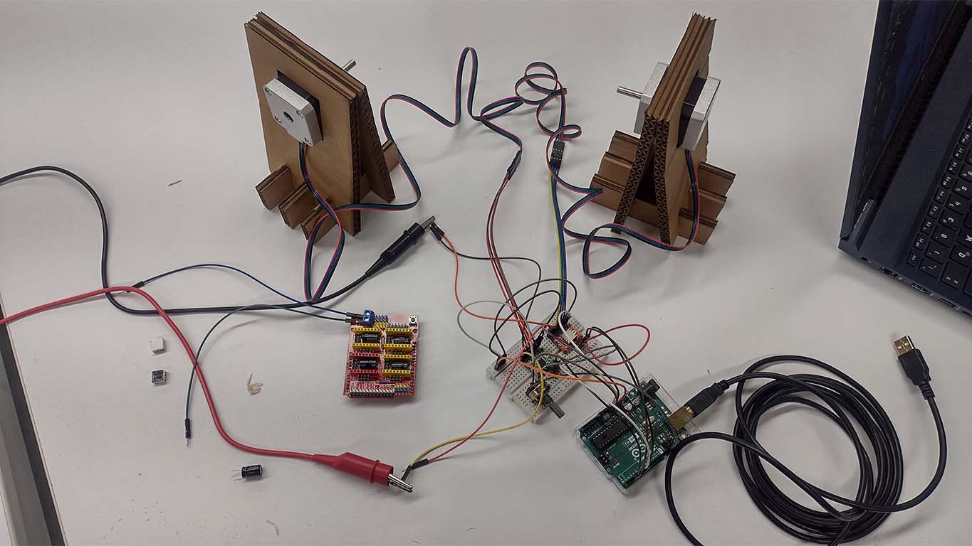
ELECTRONIC DESIGN
For the electronic part, in the first spiral I began my steps of connecting and programming stepper motors, since I did not have the opportunity to do so previously. For my first spiral the idea was to understand the operation, connection and programming of these output devices. To speed up the process and move forward with the spiral I had to use the ARDUINO UNO and the SHIELD CNC V3 to understand everything mentioned. Here is a photograph of my first steps.

Then during the week I was able to risk and advance a little more by removing the SHIELD and only using a PROTOBOARD that has all the connections and being able to move 2 stepper motors with a single potentiometer. Here is a photograph of the process and the truth that helped me better understand the connections and functioning for the future.
RESULT OF FIRST SPIRAL
I can summarize my entire week of work on my first spiral with the following video, where I could understand that it was good to start my project earlier. We can see that the axes were not working correctly, the programming and rotation of the stepper motors were very abrupt and only the laser cut structure was fine. Here the result and failure I had, but a week of learning.
FILES
Here you can download all the files that I have made for the following assignment: