This week's assignment was:

  • GROUP ASSIGNMENT:
  • - Send a message between two projects.

  • INDIVIDUAL ASSGINMENT:
  • - design, build, and connect wired or wireless node(s) with network or bus addresses and local input &/or output device(s).

    ORGANIZATION

    Here I show how I organized myself for this week.

    Wednesday 24th: Fab Academy classes, organization for the week and review of all materials and supplies available for the assignment.
    Thursday 25Th: Review and investigation of previous documentation to understand the individual assignment. Design and milling of board for assignment.
    Friday 26th: Build, welding and first attempt to connect wired or wireless nodes.
    Saturday 27th: Enter GLOBAL OPEN TIME to show my errors and ask some questions about the assignment and develop the group assignment with my colleagues.
    Sunday: 28th: Carry out documentation of everything developed.
    Monday 29th: Review and correction of documentation. Update and changes for last commit.
    Tuesday 30th: Documentation and last commit of the week.

    GROUP ASSIGNMENT

    Here I leave the link to go to the group assignments page.

    Clic here to visit the WEEK 13 GROUP ASSIGNMENT PAGE

    TESTING THE MQTTX PROGRAM

    INSTALLING MQTTX

    For group assignment we carried out many tests of how we could send messages between projects. We first researched the ways in which we could achieve this and the one that was most recommended to us was MQTTX. Which is a platform with servers where we can send messages from our board and it communicates through a channel that allows messages to be sent between microcontrollers or boards. Here the development process.

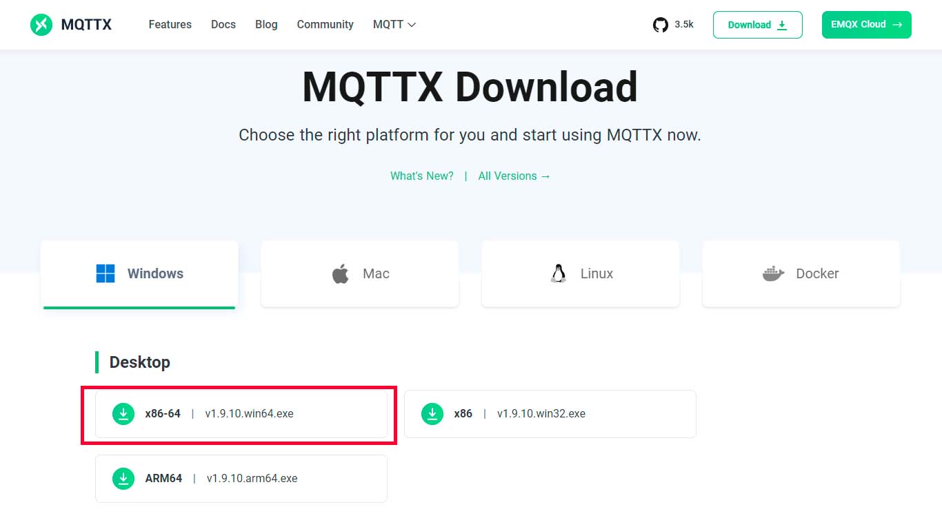
    First, we download the MQTTX provided by the server page and download. We can use it on a PC or cell phone.

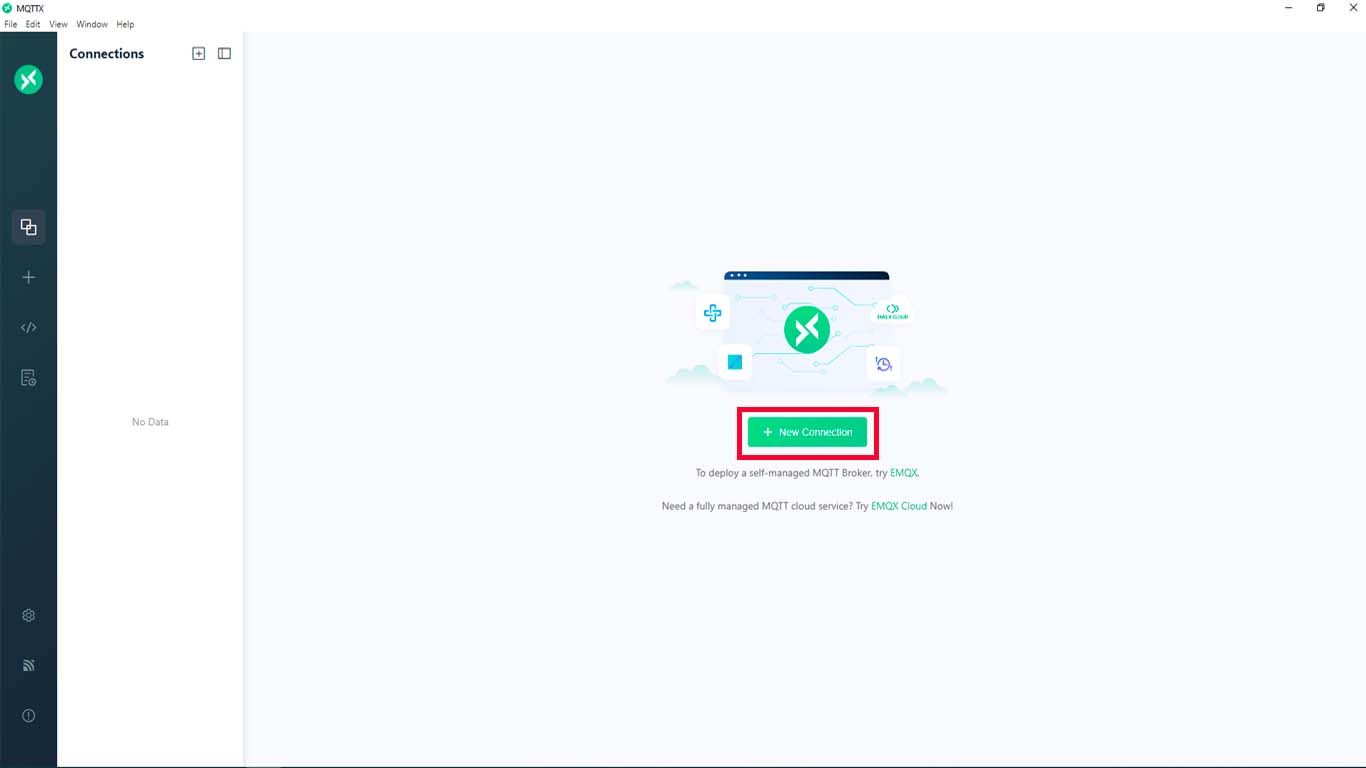
    After downloading and installing the program. We open it and the following window will appear, here we have to click on NEW CONNECTION.

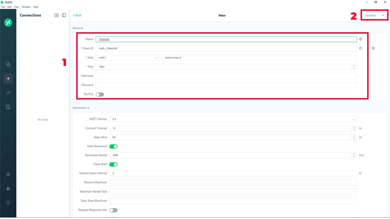
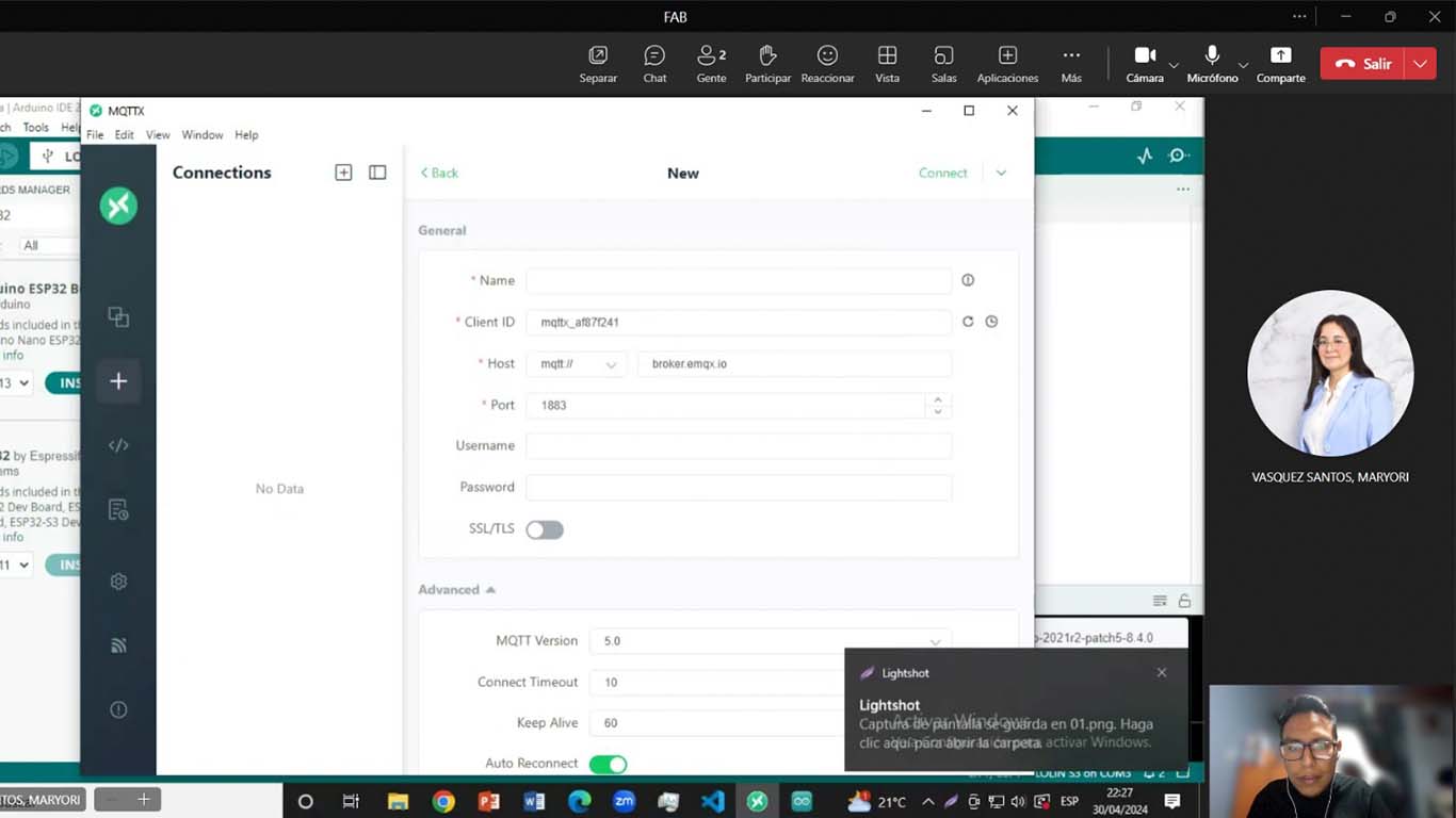
    A new window will appear where we begin to write information about the server we are creating. We only need to fill in the NAME part since the rest does not need to be changed but we must take into account the information we have. Finally, we just click on CONNECT.

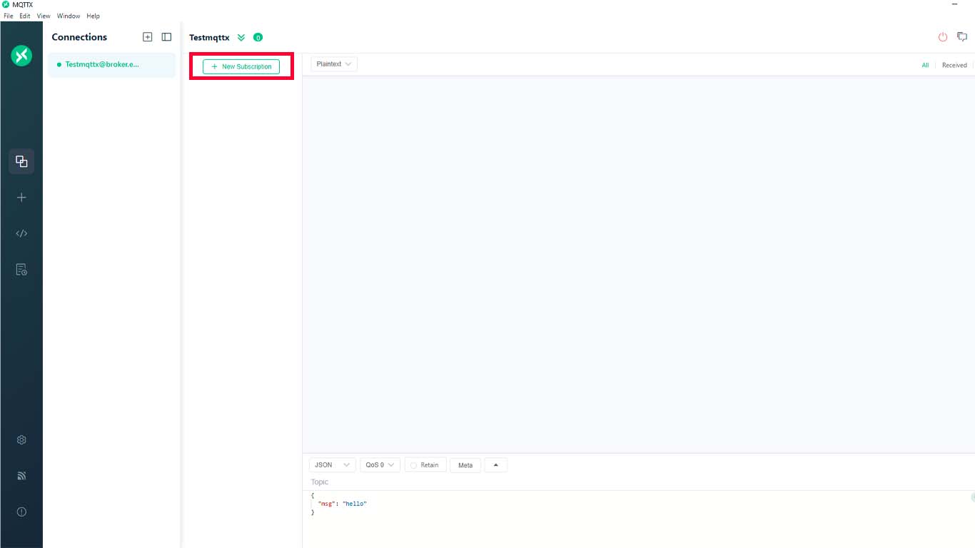
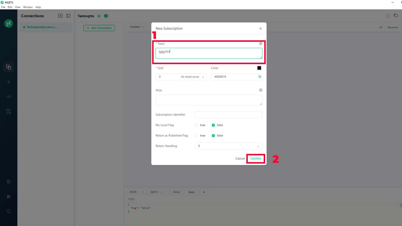
    Here all the information about the created server will appear. Here we just click on NEW SUBSCRIPTION, as the image shows. Here a pop-up window will appear to fill in information. We only need to fill out the TOPIC, which in our case will be "HANS/LED" and click confirm.

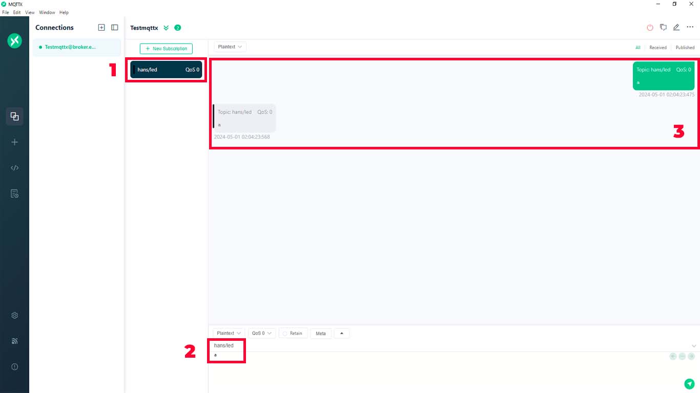
    Finally, a window will appear where the hans/led server will appear, here, we go to the bottom of the window, we change the TOPIC to the name of the server and we can send messages. In table No. 3 we can see how we send and receive the message we send. From here we are ready to start programming with this information.

    Here is a screenshot of my meeting with my colleague Maryori to do the group assignment where we were configuring the MQTTX.

    PROGRAMMING ARDUINO IDE

    In order to connect our XIAO ESP32-C3 with the server that we created, we have to put all that information in the programming, remember to put our server data, our WIFI and we upload to the microcontroller.

                                
                                    #include WiFi.h
                                        #include PubSubClient.h
                                        
                                        // Replace the next variables with your SSID/Password combination
                                        const char* ssid = "HBP WIRELES";
                                        const char* password = "923279923";
                                        
                                        // Add your MQTT Broker IP address, example:
                                        //const char* mqtt_server = "192.168.1.144";
                                        const char* mqtt_server = "broker.emqx.io";
                                        
                                        WiFiClient espClient;
                                        PubSubClient client(espClient);
                                        long lastMsg = 0;
                                        char msg[50];
                                        int value = 0;
                                        
                                        float numero = 0;
                                        
                                        // LED Pin
                                        const int ledPin = D3;
                                        
                                        void setup() {
                                          Serial.begin(115200);  
                                          setup_wifi();
                                          client.setServer(mqtt_server, 1883);
                                          client.setCallback(callback);
                                          pinMode(ledPin,OUTPUT);
                                        }
                                        
                                        void setup_wifi() {
                                          delay(10);
                                          // We start by connecting to a WiFi network
                                          Serial.println();
                                          Serial.print("Connecting to ");
                                          Serial.println(ssid);
                                        
                                          WiFi.begin(ssid, password);
                                        
                                          while (WiFi.status() != WL_CONNECTED) {
                                            delay(500);
                                            Serial.print(".");
                                          }
                                        
                                          Serial.println("");
                                          Serial.println("WiFi connected");
                                          Serial.println("IP address: ");
                                          Serial.println(WiFi.localIP());
                                        }
                                        
                                        void callback(char* topic, byte* message, unsigned int length) {
                                          Serial.print("Message arrived on topic: ");
                                          Serial.print(topic);
                                          Serial.print(". Message: ");
                                          String messageTopic;
                                          
                                          for (int i = 0; i < length; i++) {
                                            Serial.print((char)message[i]);
                                            messageTopic += (char)message[i];
                                          }
                                          Serial.println();
                                          if (String(topic) == "hans/led") {
                                            Serial.print("Changing output to ");
                                            if(messageTopic == "a"){
                                              Serial.println("on");
                                              digitalWrite(ledPin, HIGH);
                                            }
                                            else if(messageTopic == "b"){
                                              Serial.println("off");
                                              digitalWrite(ledPin, LOW);
                                            }
                                          }
                                        
                                        }
                                        
                                        void reconnect() {
                                          // Loop until we're reconnected
                                          while (!client.connected()) {
                                            Serial.print("Attempting MQTT connection...");
                                            // Attempt to connect
                                            if (client.connect("hdmsclient1025")) {
                                              Serial.println("connected");
                                              // Subscribe
                                              client.subscribe("hans/led");
                                            } else {
                                              Serial.print("failed, rc=");
                                              Serial.print(client.state());
                                              Serial.println(" try again in 5 seconds");
                                              // Wait 5 seconds before retrying
                                              delay(5000);
                                            }
                                          }
                                        }
                                        void loop() {
                                          if (!client.connected()) {
                                            reconnect();
                                          }
                                          client.loop();
                                        
                                        }


    RESULT

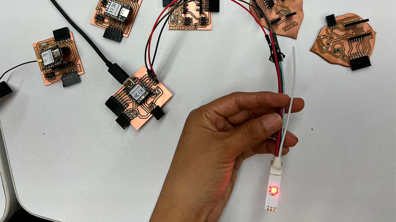
    As a result we can see that from the place where my friend Maryori is, we can send the message to turn on or off and the LED in my house turns on and off through the internet. We were surprised to achieve this.

    SENDING A MESSAGE BETWEEN TWO PROJECTS

    For the next section of my documentation that we develop as a group. I will show how a message was sent between 2 projects by cables and by wifi. We developed the first one through I2C communication, which is what we were able to achieve success with between wired communication and for Wi-Fi, we will use MQTTX so that both boards can communicate. Below is the process of each of them.

    MESSAGE BETWEEN SILVANA BOARD AND MINE - WIRES I2C

    To develop communication, we decided to use the Motion Sensor input that is connected to my board and a neopixel that we connect to Silvana's board. Before starting the communication between the 2 boards, we had to carry out a test on each board to see if it worked and whether the input and output were working correctly. Here is a screenshot of the neopixel on Silvana's board.

    After checking that both the sensor and the neopixel were working normally. We now connect both boards via I2C wiring. Where we use jammers for communication.

    PROGRAMMING

    For programming, I2C communication was taken into account so that both can work via cables. The XIAO ESP32 C3 was used on my board and a XIAO RP2040 was used on Silvana's board. Here the programming of both boards.

    HANS'S BOARD

                            
                              #include Wire.h
    
                                const int sensorPin = D10; // PIN OF XIAO ESP32 C3
                                
                                void setup() {
                                  Wire.begin(); // Start I2C communication
                                  pinMode(sensorPin, INPUT);
                                }
                                
                                void loop() {
                                  int sensorValue = digitalRead(sensorPin);
                                  Wire.beginTransmission(9); // Slave address
                                  Wire.write(sensorValue);
                                  Wire.endTransmission();
                                  delay(1000); // Wait for 1 second before reading the sensor again
                                }


    SILVANA'S BOARD

                            
                              #include Wire.h
                                #include Adafruit_NeoPixel.h
                                
                                #define PIN        10 // PIN XIAO RP2040
                                #define NUMPIXELS  1
                                
                                Adafruit_NeoPixel pixels(NUMPIXELS, PIN, NEO_GRB + NEO_KHZ800);
                                
                                void setup() {
                                  pixels.begin();
                                  Wire.begin(9); // Slave address
                                  Wire.onReceive(receiveEvent);
                                }
                                
                                void loop() {
                                  // There's no need to do anything in the slave's loop
                                }
                                
                                void receiveEvent(int bytes) {
                                  if (Wire.available()) {
                                    int sensorValue = Wire.read();
                                    if (sensorValue == 1) {
                                      // If motion is detected, set Neopixel color to red
                                      pixels.setPixelColor(0, pixels.Color(255, 0, 0)); // Red
                                      pixels.show();
                                    } else {
                                      // If no motion is detected, set Neopixel color to green
                                      pixels.setPixelColor(0, pixels.Color(0, 255, 0)); // Green
                                      pixels.show();
                                    }
                                  }
                                }


    RESULT

    Here I show you the result of the connection between the 2 plates. We can see that when the motion sensor detects movement, it changes the color of the neopixel from green to red. Here are some videos of the results.

    MESSAGE BETWEEN SILVANA BOARD AND MINE - WIFI + MQTTX

    To achieve the message between the 2 boards via WIFI, we decided to communicate between 2 XIAO ESP32 C3 microcontrollers, where Silvana's board worked as a subscriber, since it contained the neopixel as output and my board worked as a publisher, with a switch that I have. on the board to send messages via MQTTX.

    To achieve communication we use MQTTX, where we must have a publisher (my board) and a subscriber (silvana's board), where the latter receives information from the publisher, processes and performs the action that was programmed. Here I leave the work process between both plates.

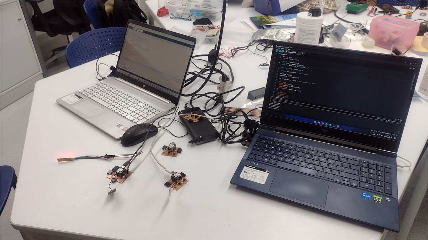
    First we connect both boards to a different computer and begin to program it so that they have communication between them via MQTTX.

    PROGRAMMING

    For programming, both boards have the XIAO ESP32 C3, where we previously carried out tests on the input and output that we were going to communicate. From there we created a TOPIC in the MQTTX to be able to read the message sent by the publisher and the subscriber read those messages and performed an action.

    HANS'S BOARD

                            
                              #include 
                                #include 
                                
                                const char* ssid = "YourSSID";
                                const char* password = "YourPassword";
                                const char* mqtt_server = "broker.emqx.io";
                                
                                const char* topic = "week13/wifi"; // Topic
                                
                                const int switchPin = D2; // Switch Pin
                                
                                WiFiClient espClient;
                                PubSubClient client(espClient);
                                
                                int lastSwitchState = HIGH; // Previous switch state
                                
                                void setup() {
                                  Serial.begin(115200);
                                  pinMode(switchPin, INPUT_PULLUP);
                                  setup_wifi();
                                  client.setServer(mqtt_server, 1883);
                                }
                                
                                void setup_wifi() {
                                  delay(10);
                                  Serial.println();
                                  Serial.print("Connecting to ");
                                  Serial.println(ssid);
                                
                                  WiFi.begin(ssid, password);
                                
                                  while (WiFi.status() != WL_CONNECTED) {
                                    delay(500);
                                    Serial.print(".");
                                  }
                                
                                  Serial.println("");
                                  Serial.println("WiFi connected");
                                  Serial.println("IP Address: ");
                                  Serial.println(WiFi.localIP());
                                }
                                
                                void reconnect() {
                                  while (!client.connected()) {
                                    Serial.print("Connecting to MQTT server...");
                                    if (client.connect("switchClient")) {
                                      Serial.println("Connected");
                                    } else {
                                      Serial.print("failed, rc=");
                                      Serial.print(client.state());
                                      Serial.println(" trying again in 5 seconds");
                                      delay(5000);
                                    }
                                  }
                                }
                                
                                void loop() {
                                  if (!client.connected()) {
                                    reconnect();
                                  }
                                  client.loop();
                                
                                  int switchState = digitalRead(switchPin);
                                  if (switchState != lastSwitchState) { // If there's a change in switch state
                                    if (switchState == LOW) {
                                      client.publish(topic, "a");
                                      Serial.println("Switch pressed");
                                    } else {
                                      client.publish(topic, "b");
                                      Serial.println("Switch released");
                                    }
                                    lastSwitchState = switchState;
                                  }
                                
                                  delay(100); // Small delay to avoid switch bounce
                                }


    SILVANA'S BOARD

                            
                              #include 
                                #include 
                                #include 
                                
                                const char* ssid = "YourSSID";
                                const char* password = "YourPassword";
                                const char* mqtt_server = "broker.emqx.io";
                                
                                const char* topic = "week13/wifi"; // same topic to publisher
                                
                                #define NEOPIXEL_PIN D10
                                #define NUM_PIXELS 1
                                
                                WiFiClient espClient;
                                PubSubClient client(espClient);
                                
                                Adafruit_NeoPixel pixels(NUM_PIXELS, NEOPIXEL_PIN, NEO_GRB + NEO_KHZ800);
                                
                                void setup() {
                                  Serial.begin(115200);
                                  setup_wifi();
                                  client.setServer(mqtt_server, 1883);
                                  client.setCallback(callback);
                                  pixels.begin();
                                }
                                
                                void setup_wifi() {
                                  delay(10);
                                  Serial.println();
                                  Serial.print("Connecting to ");
                                  Serial.println(ssid);
                                
                                  WiFi.begin(ssid, password);
                                
                                  while (WiFi.status() != WL_CONNECTED) {
                                    delay(500);
                                    Serial.print(".");
                                  }
                                
                                  Serial.println("");
                                  Serial.println("WiFi connected");
                                  Serial.println("IP Address: ");
                                  Serial.println(WiFi.localIP());
                                }
                                
                                void callback(char* topic, byte* payload, unsigned int length) {
                                  String message = "";
                                  for (int i = 0; i < length; i++) {
                                    message += (char)payload[i];
                                  }
                                  Serial.print("Message received from topic ");
                                  Serial.print(topic);
                                  Serial.print(": ");
                                  Serial.println(message);
                                
                                  if (message == "a") {
                                    pixels.setPixelColor(0, pixels.Color(255, 0, 0)); // Red
                                    pixels.show();
                                  } else {
                                    pixels.setPixelColor(0, pixels.Color(0, 255, 0)); // Green
                                    pixels.show();
                                  }
                                }
                                
                                void reconnect() {
                                  while (!client.connected()) {
                                    Serial.print("Connecting to MQTT server...");
                                    if (client.connect("neopixelClient")) {
                                      Serial.println("Connected");
                                      client.subscribe(topic);
                                    } else {
                                      Serial.print("Failed, rc=");
                                      Serial.print(client.state());
                                      Serial.println(" trying again in 5 seconds");
                                      delay(5000);
                                    }
                                  }
                                }
                                
                                void loop() {
                                  if (!client.connected()) {
                                    reconnect();
                                  }
                                  client.loop();
                                }


    RESULT

    Here I show you the result of the connection between the 2 plates. We can see that when the motion sensor detects movement, it changes the color of the neopixel from green to red. Here are some videos of the results.

    SUPPORT AND FEEDBACK

    GLOBAL OPEN TIME

    On Saturday I joined the GLOBAL OPEN TIME group as always with Adrián, Rico, Pablo and the other colleagues. They supported me a lot about the assignment and understanding what the requirements were and we even played a small virtual game with Pablo to see if we were paying attention to class on Wednesday. You're going to excuse me but this time I don't have a screenshot and that's why I had to format my PC because it had a lot of information and it was slow. There went the photos from that day. I was sad to realize that I deleted them. Thank you teachers for your support.

    MEETING WITH INSTRUCTOR

    To achieve this week's assignment I also had support from my Instructor Ulysses, the truth is that he supported me a lot to understand communication and how I could work. Thank you very much teacher for the support.

    INDIVIDUAL ASSIGNMENT

    REDESIGN HM BOARD

    To carry out the individual assignment, I redesigned my development board that I was working on in the past weeks because it did not have I2C communication or UART. Therefore, I designed 2 new boards from the HM board and designed a MASTER board and a NODE board. Here the process.
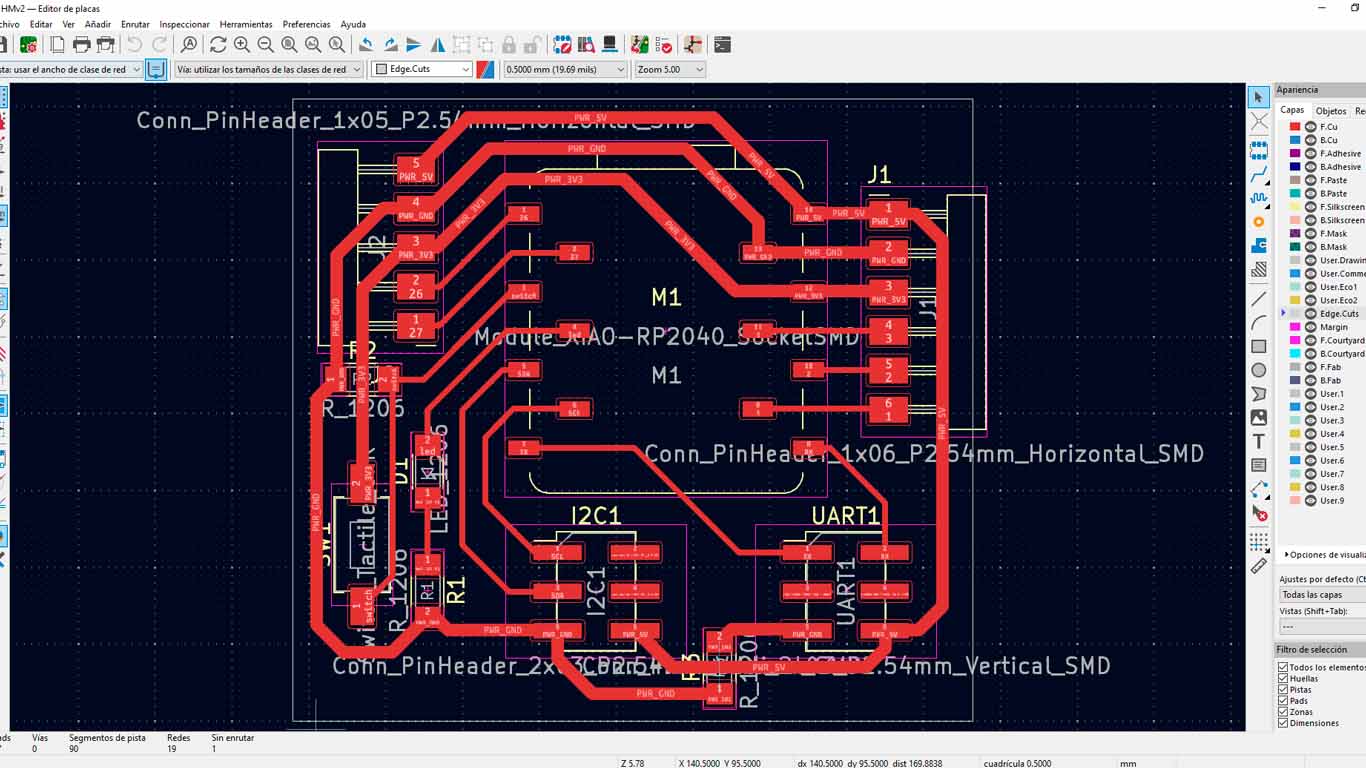
    HM MASTER BOARD

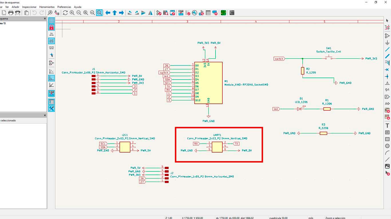
    For my HM MASTER board I wanted it to have the connections to be able to transmit I2C and UART on it since the previous one did not contain it. So I added these pins, where I took into account the RX and TX pins for the UART connection between boards.

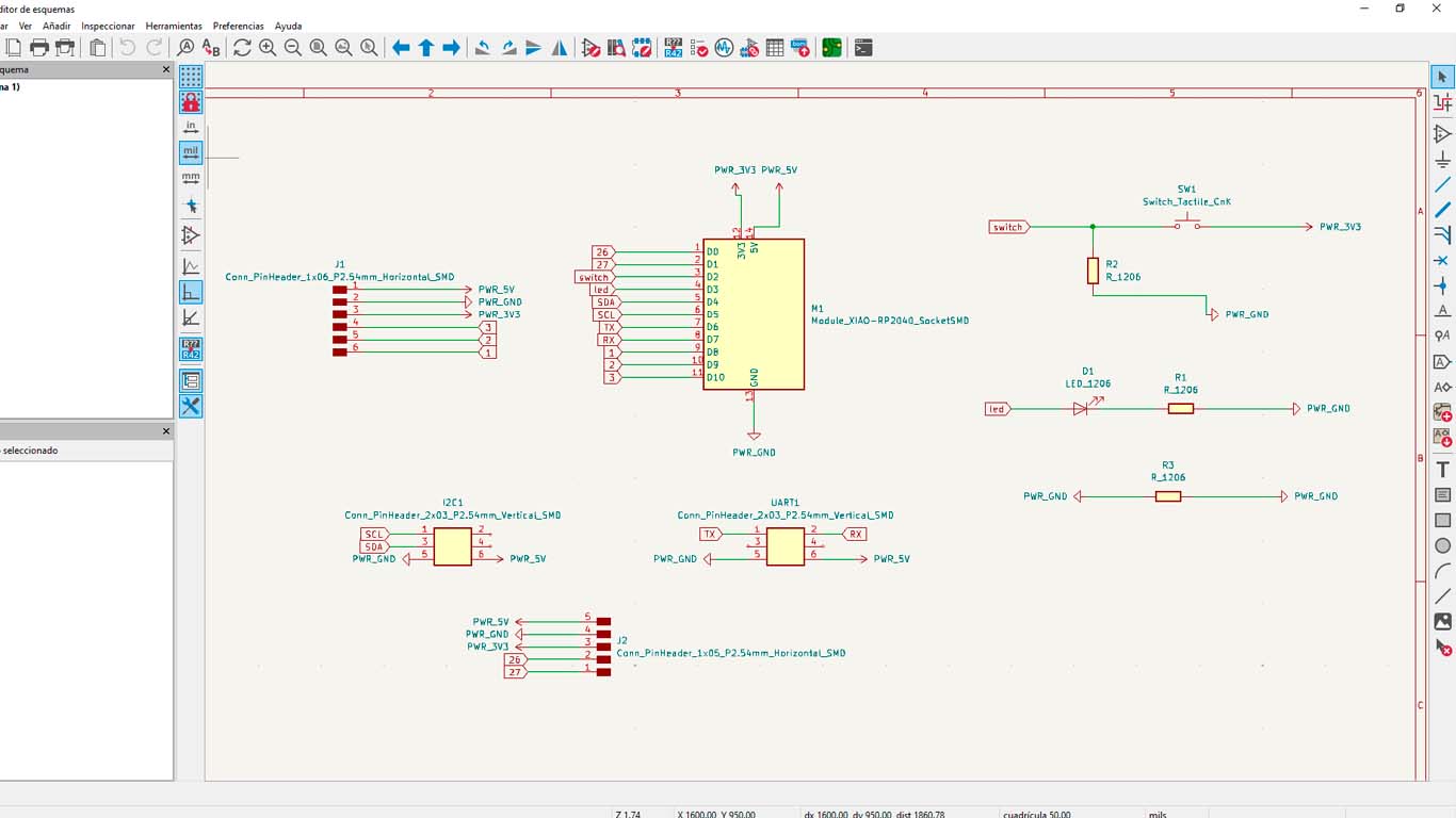
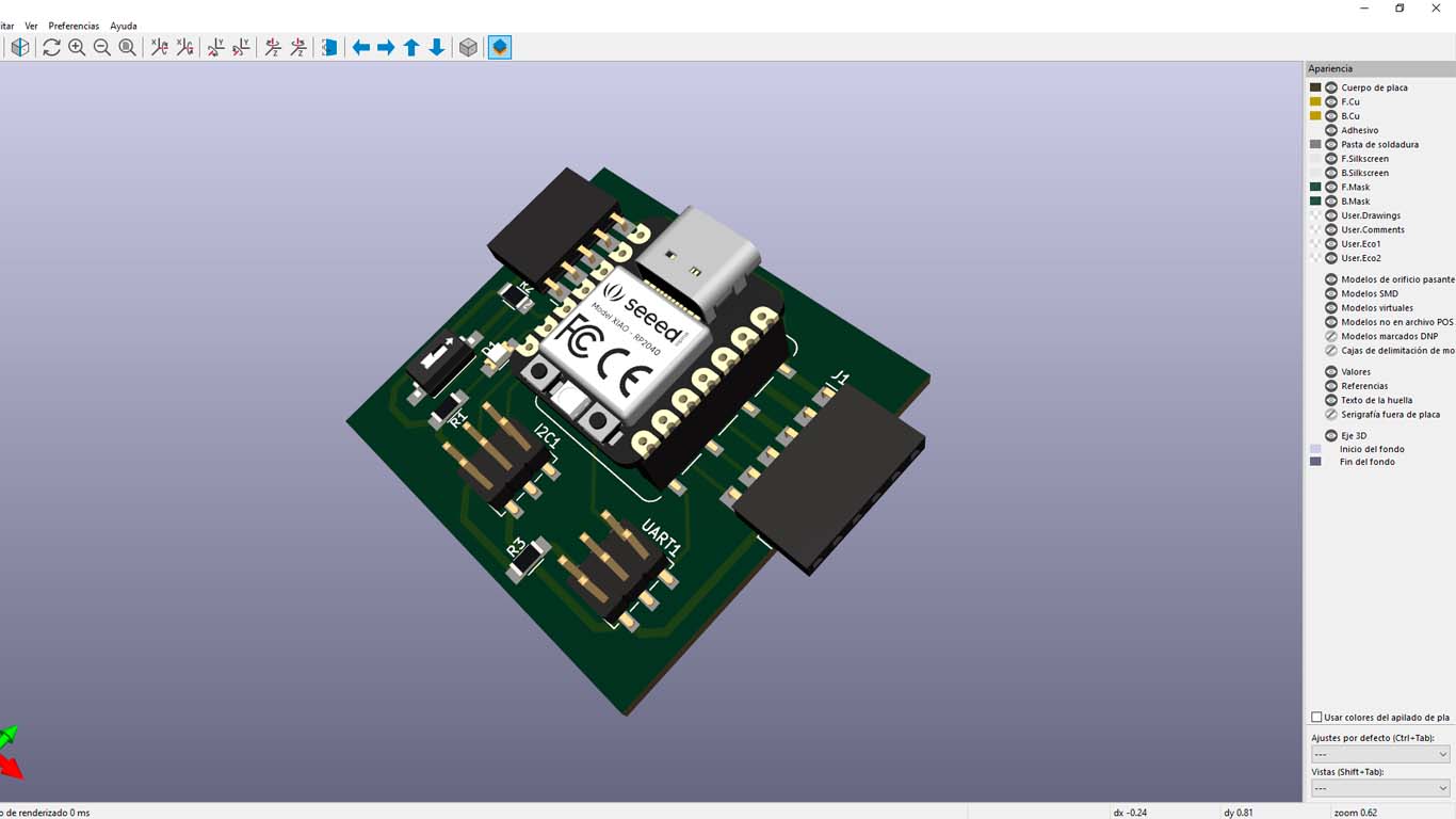
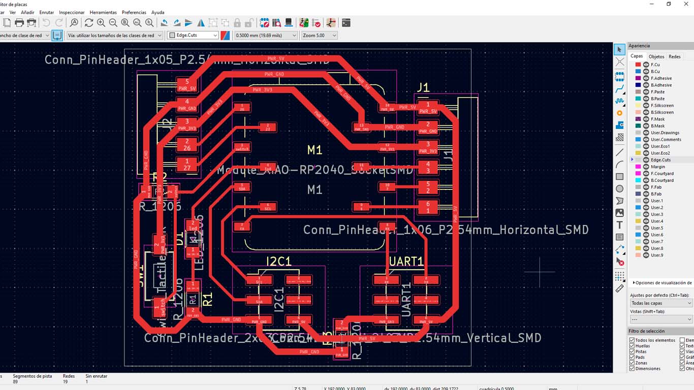
    Here is a 3D capture of what my board will look like and you can see at the bottom the new 6-pin connectors to achieve the I2C and UART connection. You may wonder why 6 pins was the only connector I had in the FAB LAB this week and to achieve this assignment I figured out how to develop it and it worked.

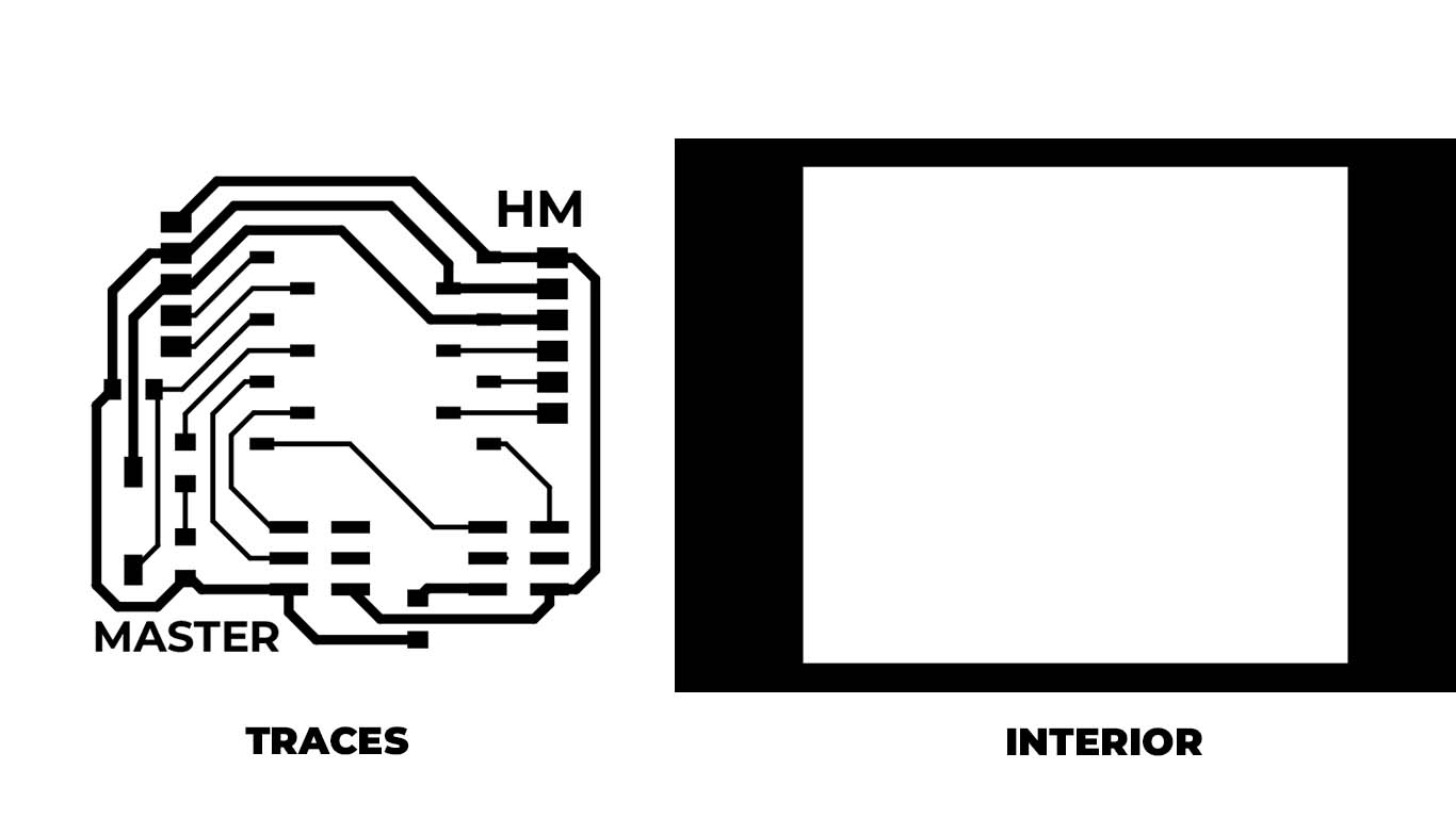
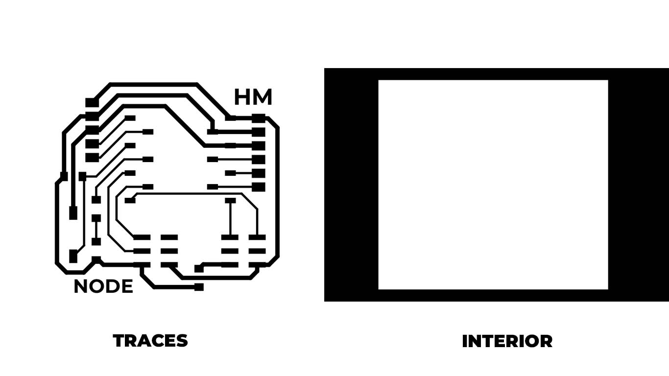
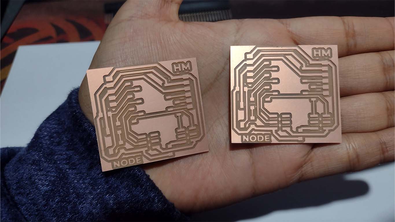
    After reviewing all the connections, I went on to export the traces and the interior of the board for milling in MODS.CE. In the FILES part of my documentation you can find my HM MASTER file.

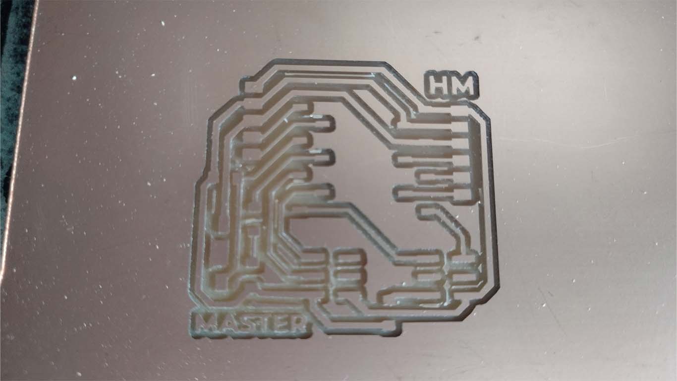
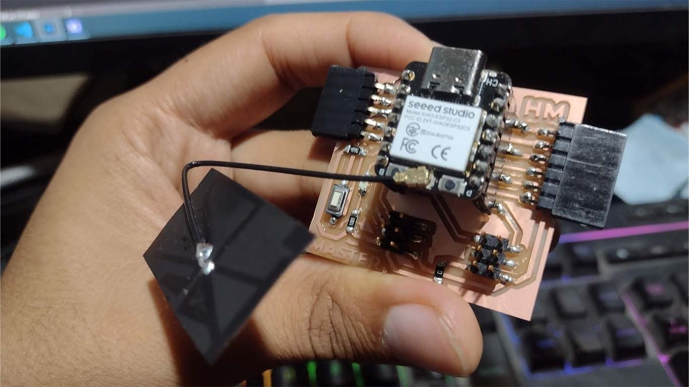
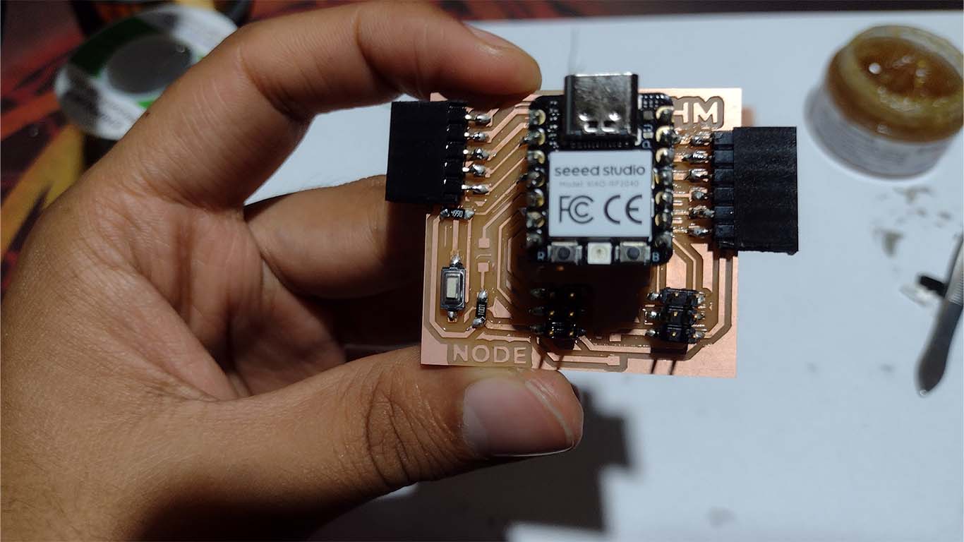
    Finally, after obtaining the milled board I began to solder all the electronic components that I considered important for the board and here is a photograph of how the HM MASTER turned out.

    HM NODO BOARD

    For the NODE BOARD I had the same design as my master board but what changes is the connection for the UART protocol. Let's remember that this type of connection has RX AND TX, which means receiver and transmitter. It is important to keep in mind that to achieve this connection the pins must be exchanged so that it can be RX (master board) with TX of (node 1) and TX (master board) with RX of (node). It is important to take this into account, for the I2C protocol if there are no problems.

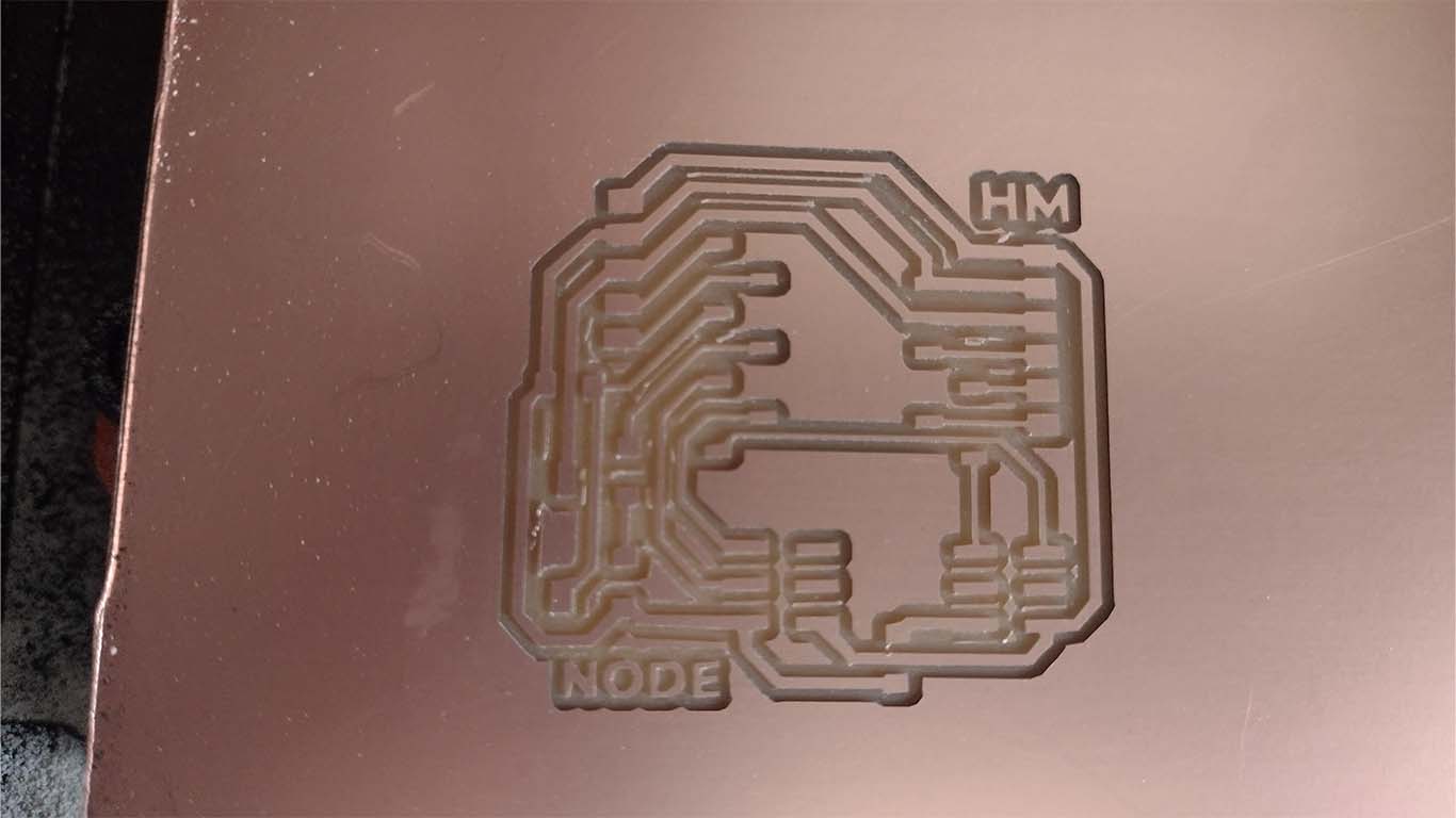
    Here is a screenshot of how the traces and the interior turned out, which I also exported to the mods for their respective milling. Here are some screenshots of the process.

    Finally, after milling and soldering all the components that I placed on the board, here is the result of my node board. For this board I will use the XIAO RP2040 for the assignment.

    PROGRAMMING XIAO ESP32-C3

    It is the first time that I am going to program the XIAO ESP32-C3 because I had not used it previously. Here I show you how to configure the ARDUINO IDE to be able to obtain the microcontroller libraries and to be able to carry out the programming.

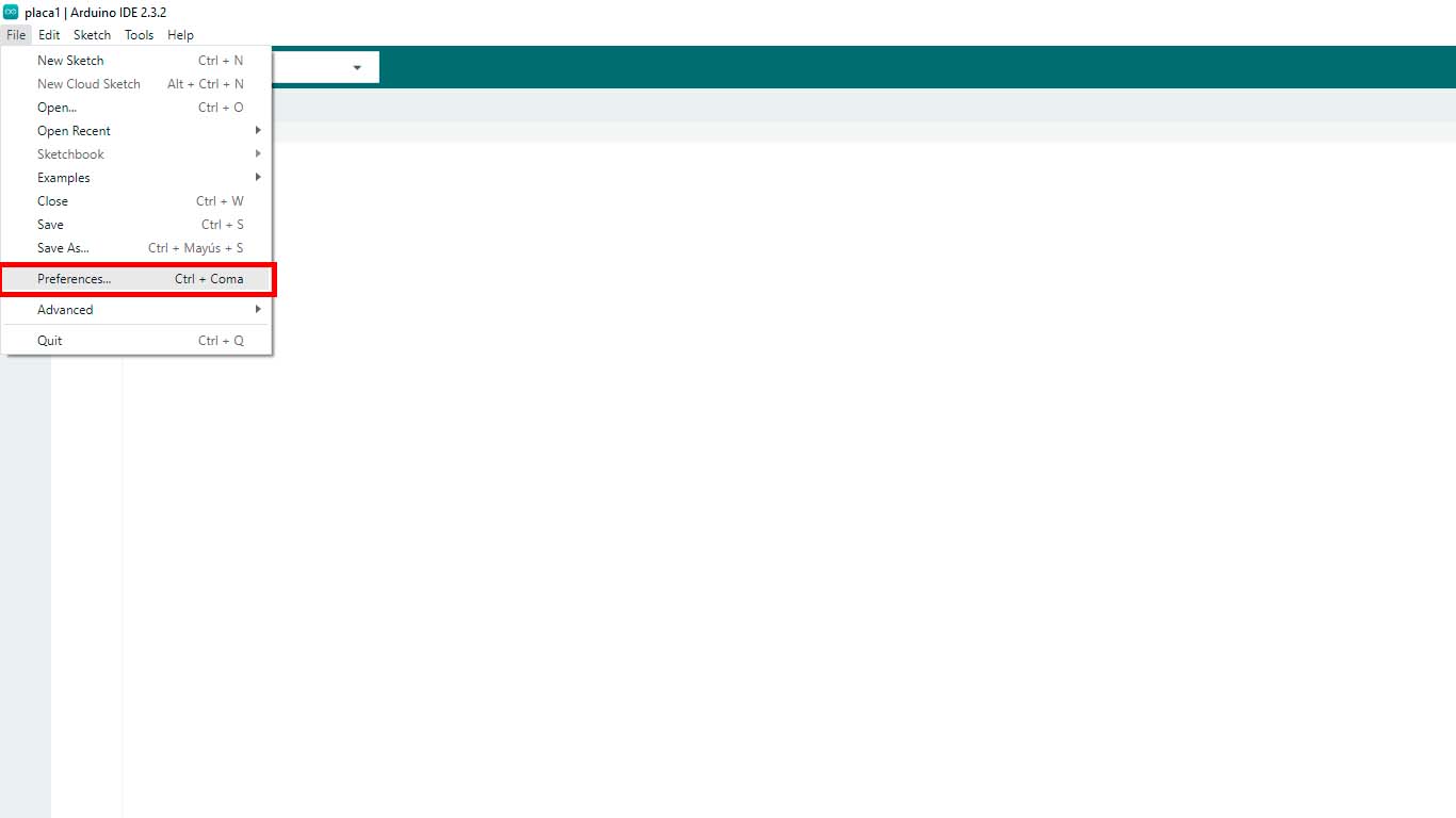
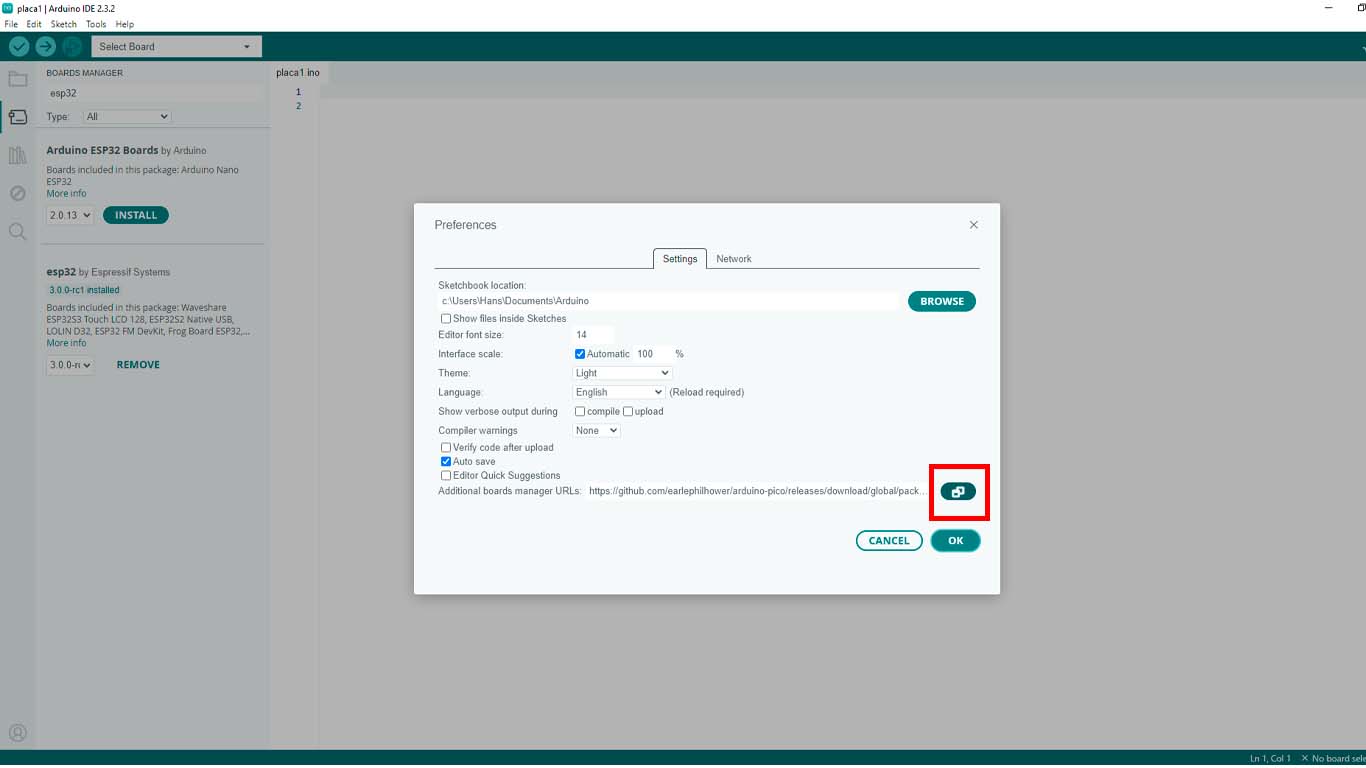
    First we open the ARDUINO IDE program, and we go to the FILE tab until we find the PREFERENCES tab and we click on it.

    A window will open where we have to go to the button that is inside the red rectangle and click on it.

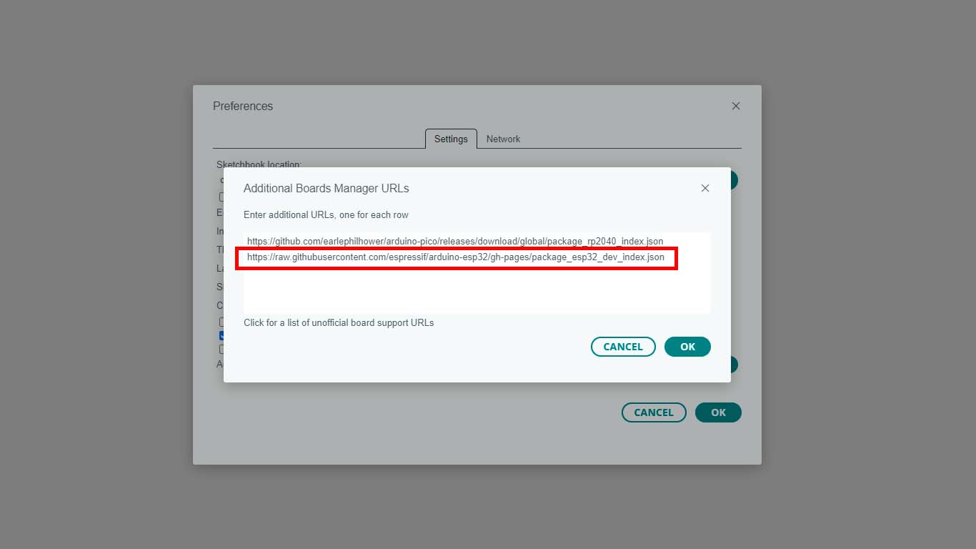
    Here we have to paste the link that I will leave below. This is to import all the documents and information about the XIAO ESP32 - C3 that we need for programming. Here the link:

    LINK OF XIAO ESP32-C3

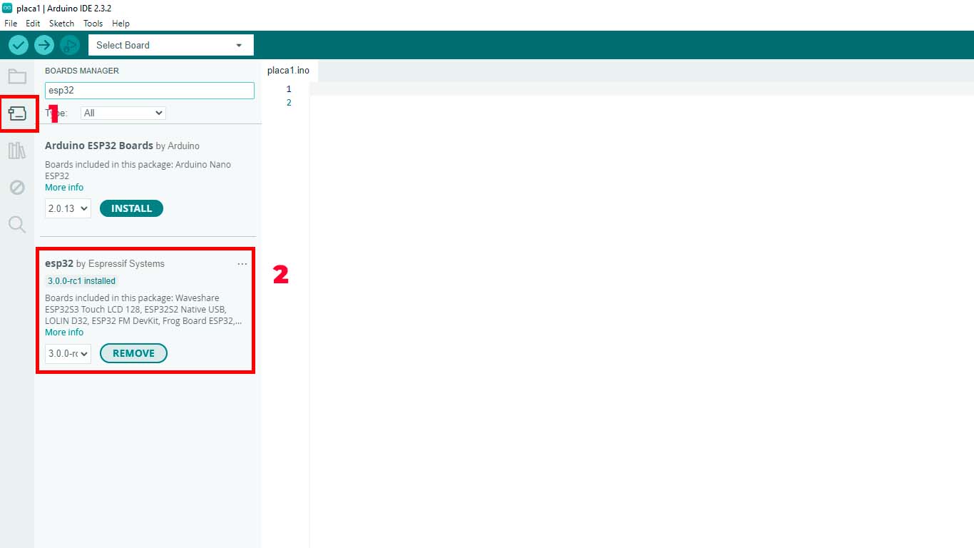
    Finally, after giving ok to the previous step, we have to go to the BOARDS MANAGER tab that we find on the left side of the program and it is also in the TOOLS/BOARS/BOARDS MANAGER tab. Here we have to write only "ESP 32" and click on install the ESPRESSIF SYSTEMS option.

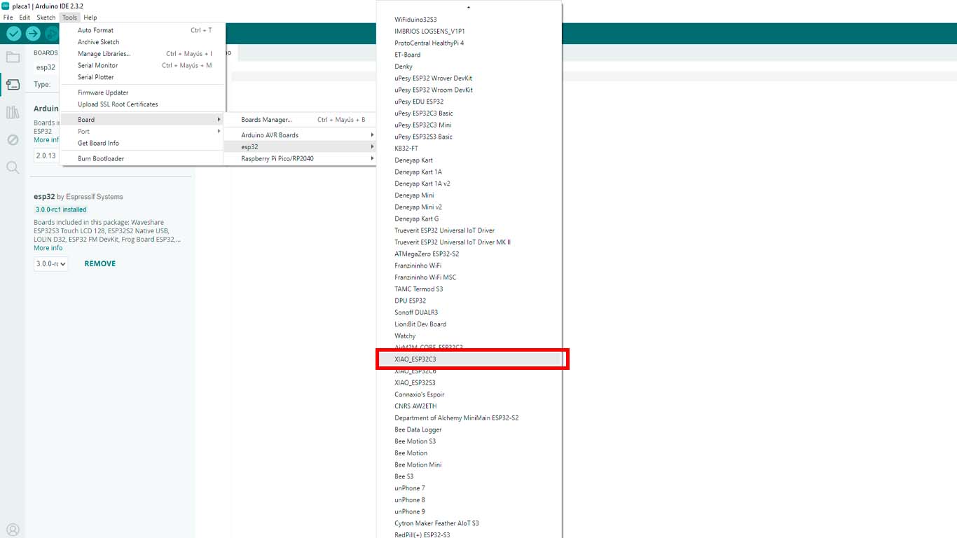
    To start programming, we have to find the microcontroller in the program. In the following photograph we can see where we find the XIAO ESP32-C3 and we click on it and we are ready for programming.

    WIRED I2C

    SYNCING OF LEDS

    To begin the communication between boards and microcontrollers I wanted to start with a simple one, which is LED synchronization, since each board has an LED, the idea is that these LEDs turn on in order, from the master board to the last node and turn on again. repeat. Here the process.

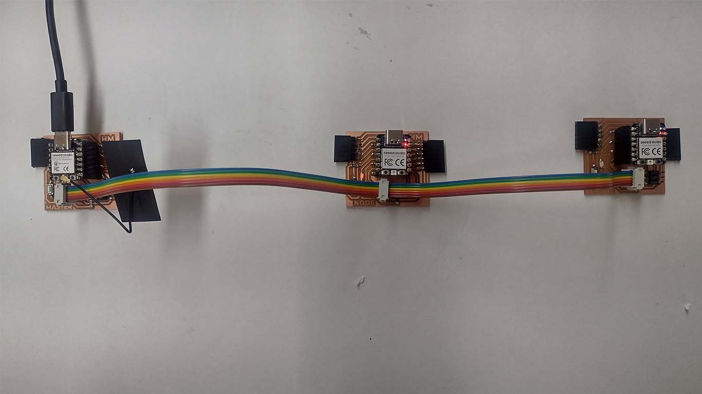
    To achieve LED communication, we have to program the 3 boards first. Here I leave the programming codes for the ARDUINO IDE of the MASTER and the NODES.

    PROGRAMMING

    MASTER BOARD - LED

                                
                                    #include Wire.h
    
                                        #define LED_PIN D3
                                        #define SLAVE2_ADDRESS 10
                                        #define SLAVE3_ADDRESS 11
                                        
                                        void setup() {
                                          Wire.begin();
                                          pinMode(LED_PIN, OUTPUT);
                                        }
                                        
                                        void loop() {
                                          // Turn on the LED on the master board
                                          digitalWrite(LED_PIN, HIGH);
                                          delay(3000); // Wait for 3 seconds
                                          digitalWrite(LED_PIN, LOW);
                                          
                                          // Send signal to board 2 (first slave board)
                                          Wire.beginTransmission(SLAVE2_ADDRESS);
                                          Wire.write(1); // Any value representing turning on the LED
                                          Wire.endTransmission();
                                          delay(3000); // Wait for 3 seconds
                                          Wire.beginTransmission(SLAVE2_ADDRESS);
                                          Wire.write(0); // Any value representing turning off the LED
                                          Wire.endTransmission();
                                          
                                          // Send signal to board 3 (second slave board)
                                          Wire.beginTransmission(SLAVE3_ADDRESS);
                                          Wire.write(1); // Any value representing turning on the LED
                                          Wire.endTransmission();
                                          delay(3000); // Wait for 3 seconds
                                          Wire.beginTransmission(SLAVE3_ADDRESS);
                                          Wire.write(0); // Any value representing turning off the LED
                                          Wire.endTransmission();
                                        }


    NODE BOARD 1 - LED

                                
                                    #include Wire.h
    
                                        #define LED_PIN 29
                                        
                                        void setup() {
                                          Wire.begin(10); // Address of board 3 (second slave board)
                                          Wire.onReceive(receiveEvent);
                                          pinMode(LED_PIN, OUTPUT);
                                        }
                                        
                                        void loop() {
                                          delay(100);
                                        }
                                        
                                        void receiveEvent(int bytes) {
                                          while (Wire.available()) {
                                            int command = Wire.read();
                                            if (command == 1) {
                                              digitalWrite(LED_PIN, HIGH); // Turn on LED
                                              delay(3000); // Wait for 3 seconds
                                              digitalWrite(LED_PIN, LOW); // Turn off LED
                                            }
                                          }
                                        }


    NODE BOARD 2 - LED

                                
                                    #include Wire.h
    
                                        #define LED_PIN 29
                                        
                                        void setup() {
                                          Wire.begin(11); // Address of board 3 (second slave board)
                                          Wire.onReceive(receiveEvent);
                                          pinMode(LED_PIN, OUTPUT);
                                        }
                                        
                                        void loop() {
                                          delay(100);
                                        }
                                        
                                        void receiveEvent(int bytes) {
                                          while (Wire.available()) {
                                            int command = Wire.read();
                                            if (command == 1) {
                                              digitalWrite(LED_PIN, HIGH); // Turn on LED
                                              delay(3000); // Wait for 3 seconds
                                              digitalWrite(LED_PIN, LOW); // Turn off LED
                                            }
                                          }
                                        }


    RESULT

    As a result we can see that the LEDs do have synchronization on the master board and the nodes. Each LED turns on when the previous one turns off. First I2C communication test achieved.
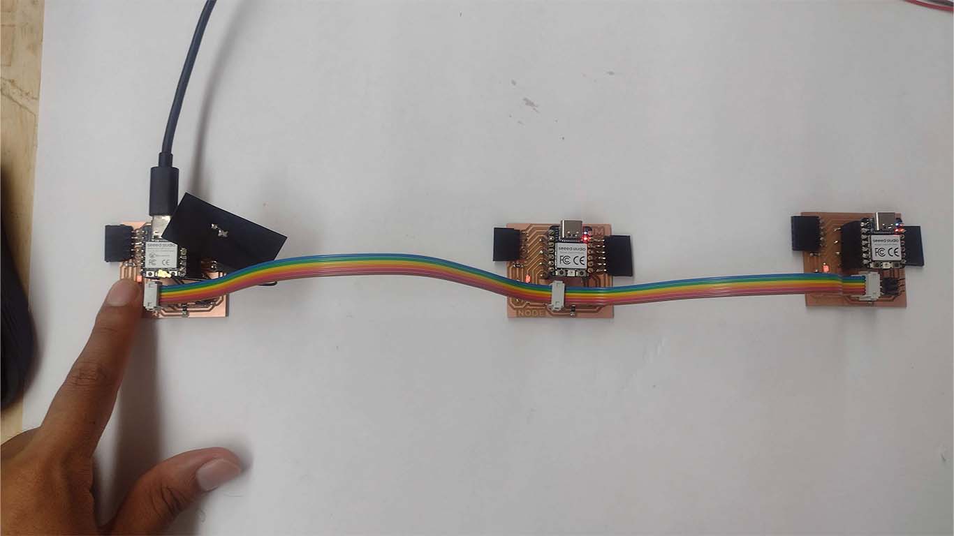
    SWITCH + LEDS

    For the second communication test, the idea is to try to turn on the LEDS of the nodes from the SWITCH that I have on the master. The idea is that the SWITCH functions as INPUT and the LEDs have the characteristic of being OUTPUT. Here the process.

    To achieve the following process, we have to program both the master board and we can repeat the programming for node 1 and node 2 since they will only turn on this time. Here I leave the programming code for ARDUINO IDE.

    PROGRAMMING

    MASTER BOARD - SWITCH

                                
                                    #include Wire.h
    
                                        #define BUTTON_PIN 2
                                        #define LED_PIN 3
                                        #define SLAVE2_ADDRESS 10
                                        #define SLAVE3_ADDRESS 11
                                        
                                        void setup() {
                                          Wire.begin();
                                          pinMode(BUTTON_PIN, INPUT_PULLUP);
                                          pinMode(LED_PIN, OUTPUT);
                                        }
                                        
                                        void loop() {
                                          bool buttonState = digitalRead(BUTTON_PIN);
                                        
                                          if (buttonState == LOW) {
                                            // Turn on the LED on the master board
                                            digitalWrite(LED_PIN, HIGH);
                                            
                                            // Send signal to turn on the LEDs on the slave boards
                                            Wire.beginTransmission(SLAVE2_ADDRESS);
                                            Wire.write(1); // Turn on LED
                                            Wire.endTransmission();
                                        
                                            Wire.beginTransmission(SLAVE3_ADDRESS);
                                            Wire.write(1); // Turn on LED
                                            Wire.endTransmission();
                                          } else {
                                            // Turn off the LED on the master board
                                            digitalWrite(LED_PIN, LOW);
                                            
                                            // Send signal to turn off the LEDs on the slave boards
                                            Wire.beginTransmission(SLAVE2_ADDRESS);
                                            Wire.write(0); // Turn off LED
                                            Wire.endTransmission();
                                        
                                            Wire.beginTransmission(SLAVE3_ADDRESS);
                                            Wire.write(0); // Turn off LED
                                            Wire.endTransmission();
                                          }
                                        
                                          // Wait briefly to avoid rapid repetitions due to button bounce
                                          delay(50);
                                        }


    NODE BOARD 1 AND 2 - LED

                                
                                    #include Wire.h
    
                                        #define LED_PIN 29
                                        
                                        void setup() {
                                          Wire.begin(); // Start I2C communication
                                          Wire.onReceive(receiveEvent); // Set up data reception function
                                          pinMode(LED_PIN, OUTPUT); // Configure LED pin as output
                                        }
                                        
                                        void loop() {
                                          delay(100); // Small pause to stabilize the loop
                                        }
                                        
                                        void receiveEvent(int bytes) {
                                          while (Wire.available()) {
                                            int command = Wire.read(); // Read the command sent by the master
                                            if (command == 1) {
                                              digitalWrite(LED_PIN, HIGH); // Turn on the LED
                                            } else {
                                              digitalWrite(LED_PIN, LOW); // Turn off the LED
                                            }
                                          }
                                        }


    RESULT

    As a result, the programming for the switch to turn on the LEDs of the nodes works. Here is a video of the result.

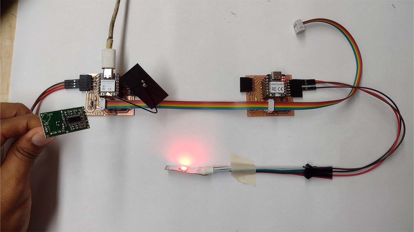
    MOTION SENSOR + LEDS

    Now I carried out a test with a motion sensor, the idea is to ensure that when the sensor reads motion detection, the LEDs turn on and when it does not detect movement, the LEDs turn off. Here the development with a sensor.

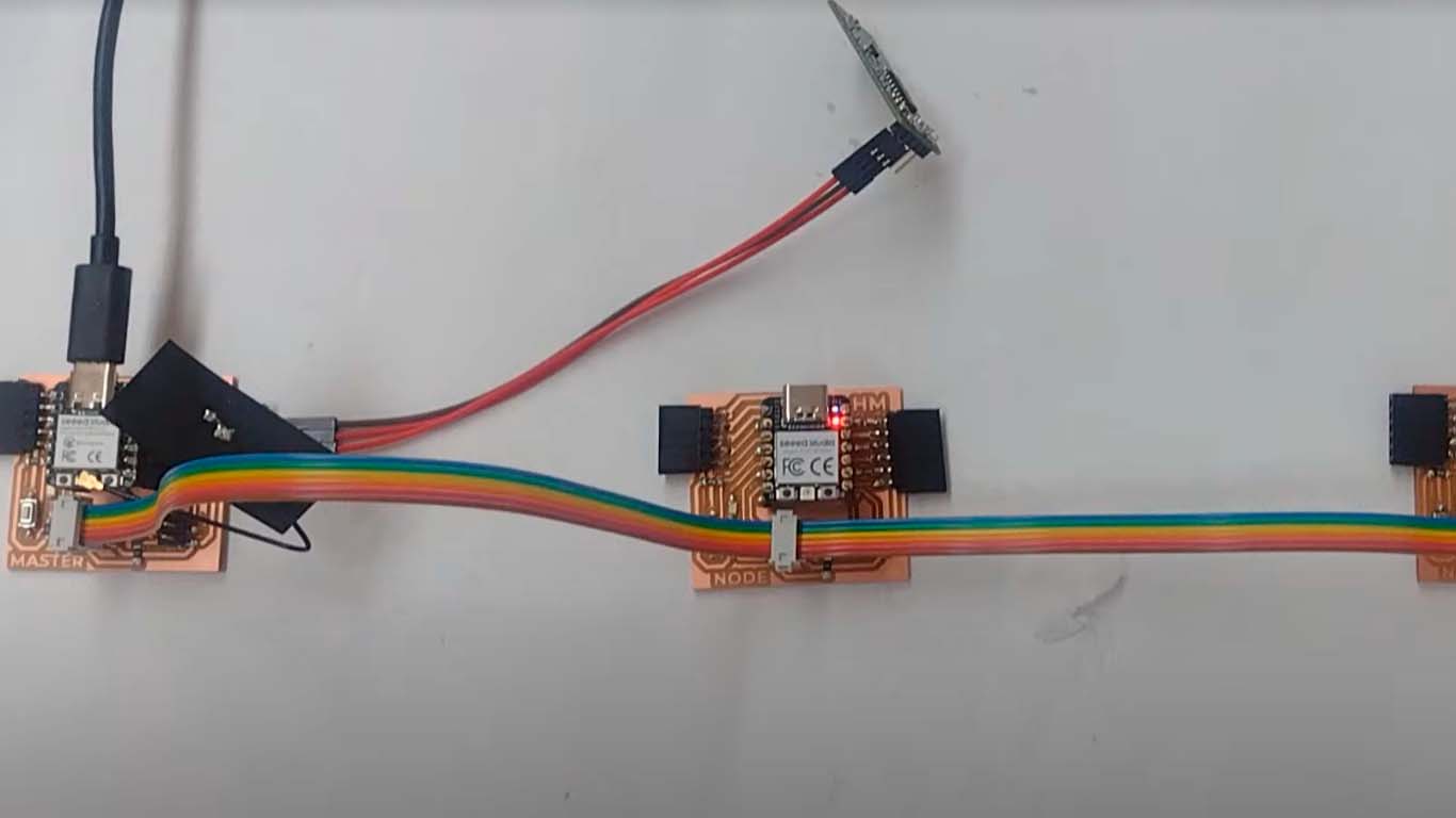
    To achieve the next challenge, we will do the programming for the master board and each node since it is necessary for everyone to communicate to know when the sensor detects movement and when it does not, so the LEDs that function as OUTPUTS can know when moment to catch on and not according to the information.

    PROGRAMMING

    MASTER BOARD - MOTION SENSOR

                                
                                    #include Wire.h
    
                                        #define MOTION_SENSOR_PIN 10
                                        #define SLAVE2_ADDRESS 10
                                        #define SLAVE3_ADDRESS 11
                                        
                                        bool motionDetected = false;
                                        
                                        void setup() {
                                          Wire.begin();
                                          Serial.begin(9600); // Start serial communication to monitor the sensor's status
                                          pinMode(MOTION_SENSOR_PIN, INPUT);
                                        }
                                        
                                        void loop() {
                                          // Read the state of the motion sensor
                                          motionDetected = digitalRead(MOTION_SENSOR_PIN);
                                        
                                          // Print the sensor state to the serial monitor
                                          Serial.print("Motion sensor state: ");
                                          Serial.println(motionDetected ? "DETECTED" : "NOT DETECTED");
                                        
                                          // Send signal to slave boards according to motion sensor state
                                          if (motionDetected) {
                                            // If motion is detected, send command to turn on LEDs on slave boards
                                            Wire.beginTransmission(SLAVE2_ADDRESS);
                                            Wire.write(1); // Turn on LED
                                            Wire.endTransmission();
                                        
                                            Wire.beginTransmission(SLAVE3_ADDRESS);
                                            Wire.write(1); // Turn on LED
                                            Wire.endTransmission();
                                          } else {
                                            // If no motion is detected, send command to turn off LEDs on slave boards
                                            Wire.beginTransmission(SLAVE2_ADDRESS);
                                            Wire.write(0); // Turn off LED
                                            Wire.endTransmission();
                                        
                                            Wire.beginTransmission(SLAVE3_ADDRESS);
                                            Wire.write(0); // Turn off LED
                                            Wire.endTransmission();
                                          }
                                        
                                          // Wait for a brief period before repeating the sensor reading
                                          delay(100);
                                        }


    BOARD NODE 1 - LED

                                
                                    #include Wire.h
    
                                        #define LED_PIN 29
                                        
                                        void setup() {
                                          Wire.begin(10); // Dirección de la placa 2
                                          Wire.onReceive(receiveEvent);
                                          pinMode(LED_PIN, OUTPUT);
                                        }
                                        
                                        void loop() {
                                          // No se necesita lógica adicional en el bucle principal
                                        }
                                        
                                        void receiveEvent(int bytes) {
                                          while (Wire.available()) {
                                            int command = Wire.read();
                                            if (command == 1) {
                                              // Si se recibe un comando 1, encender el LED
                                              digitalWrite(LED_PIN, HIGH);
                                            } else {
                                              // Si se recibe otro valor, apagar el LED
                                              digitalWrite(LED_PIN, LOW);
                                            }
                                          }
                                        }


    BOARD NODE 2 - LED

                                
                                    #include Wire.h
    
                                        #define LED_PIN 29
                                        
                                        void setup() {
                                          Wire.begin(11); // Dirección de la placa 3
                                          Wire.onReceive(receiveEvent);
                                          pinMode(LED_PIN, OUTPUT);
                                        }
                                        
                                        void loop() {
                                          // No se necesita lógica adicional en el bucle principal
                                        }
                                        
                                        void receiveEvent(int bytes) {
                                          while (Wire.available()) {
                                            int command = Wire.read();
                                            if (command == 1) {
                                              // Si se recibe un comando 1, encender el LED
                                              digitalWrite(LED_PIN, HIGH);
                                            } else {
                                              // Si se recibe otro valor, apagar el LED
                                              digitalWrite(LED_PIN, LOW);
                                            }
                                          }
                                        }


    RESULT

    As a result we can see that when the sensor detects movement, the LEDs of the nodes turn on and if it does not detect movement, they turn off.

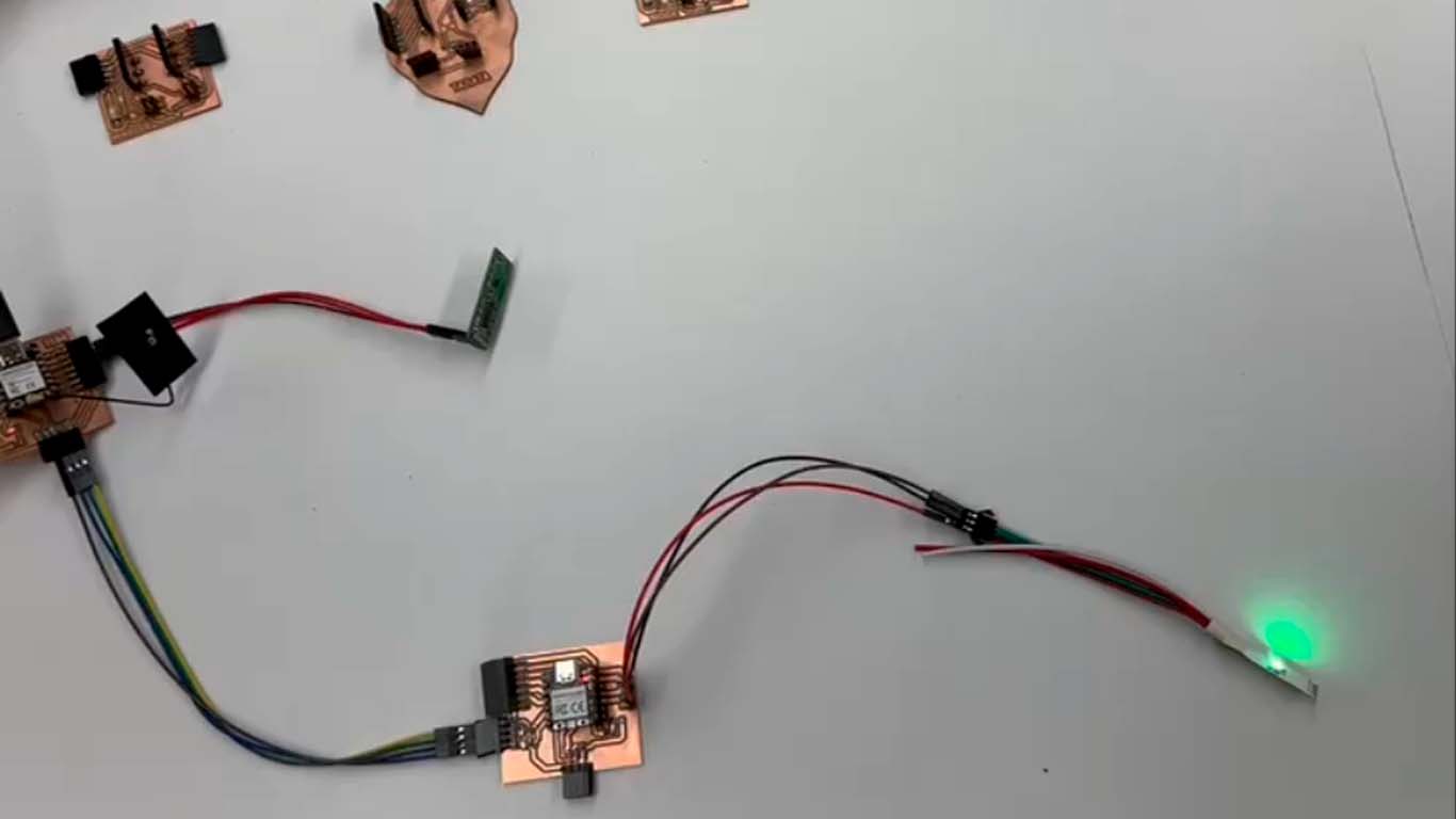
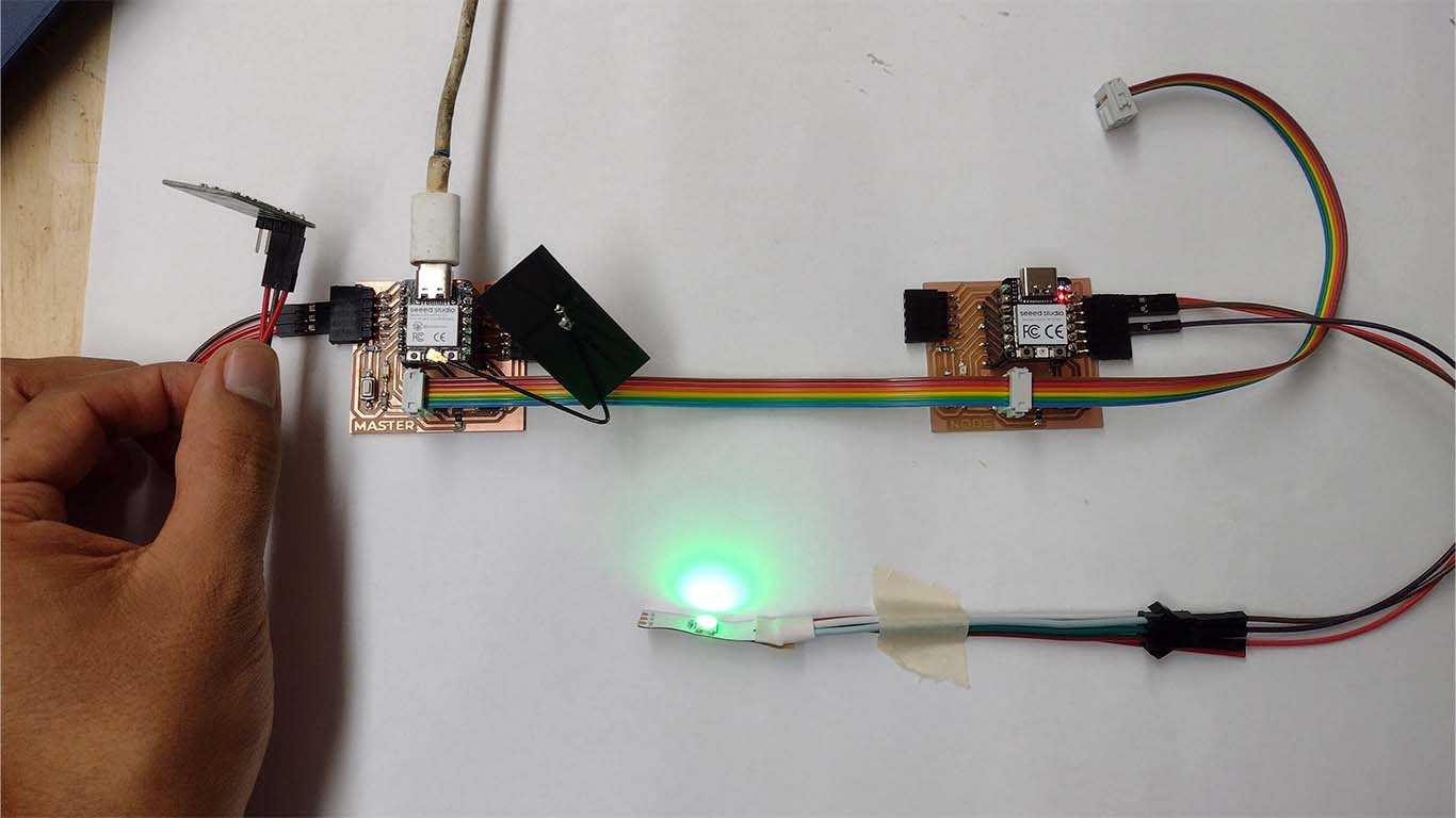
    MOTION SENSOR + NEOPIXEL

    Now we will carry out the test with a motion sensor as input on the master board and a neopixel on a node as output. Communication is via I2C and when the motion detector detects movement it turns the neopixel red and if it does not detect movement it turns green. Here are some screenshots and the process.

    Only by having 2 boards, we will program each of them so that it can work according to what was mentioned above, now the programming.

    PROGRAMMING

    MASTER BOARD - MOTION SENSOR

                                
                                    #include Wire.h
    
                                        #define SENSOR_PIN 26 // Pin where the motion sensor is connected
                                        
                                        void setup() {
                                          Serial.begin(9600); // Start serial communication
                                          Wire.begin(); // Initialize I2C communication
                                          pinMode(SENSOR_PIN, INPUT); // Set motion sensor pin as input
                                        }
                                        
                                        void loop() {
                                          // Read the state of the motion sensor
                                          int motionState = digitalRead(SENSOR_PIN);
                                        
                                          // Send the motion sensor state over serial port
                                          if (motionState == HIGH) {
                                            Serial.println("Motion detected");
                                          } else {
                                            Serial.println("No motion detected");
                                          }
                                        
                                          // Send the motion sensor state to the second board via I2C
                                          Wire.beginTransmission(8); // Address of the second board on the I2C bus
                                          Wire.write(motionState); // Send the motion sensor state
                                          Wire.endTransmission();
                                        
                                          delay(100); // Small delay before reading the motion sensor state again
                                        }                                    


    BOARD NODE 1 - NEOPIXEL

                                
                                    #include Wire.h
                                        #include Adafruit_NeoPixel.h
                                        
                                        #define NEOPIXEL_PIN 3  // Pin donde está conectado el NeoPixel
                                        #define NUM_PIXELS 1    // Número de NeoPixels en la tira
                                        
                                        Adafruit_NeoPixel pixels(NUM_PIXELS, NEOPIXEL_PIN, NEO_GRB + NEO_KHZ800);
                                        
                                        void setup() {
                                          Wire.begin(8); // Inicializa la comunicación I2C con dirección 8
                                          Wire.onReceive(receiveEvent); // Configura la función de recepción de datos I2C
                                        
                                          pixels.begin(); // Inicializa el objeto NeoPixel
                                          pixels.clear(); // Apaga todos los NeoPixels
                                          pixels.show(); // Muestra los cambios
                                        }
                                        
                                        void loop() {
                                          // No es necesario implementar código en el loop de la segunda placa
                                        }
                                        
                                        void receiveEvent(int bytes) {
                                          // Lee el estado del sensor de movimiento enviado por la primera placa
                                          int motionState = Wire.read();
                                        
                                          // Enciende o apaga el NeoPixel según el estado del sensor de movimiento
                                          if (motionState == HIGH) {
                                            // Si se detecta movimiento, establece el color del NeoPixel a rojo
                                            pixels.setPixelColor(0, pixels.Color(255, 0, 0)); // Rojo
                                          } else {
                                            // Si no se detecta movimiento, establece el color del NeoPixel a verde
                                            pixels.setPixelColor(0, pixels.Color(0, 255, 0)); // Verde
                                          }
                                          
                                          pixels.show(); // Muestra los cambios en el NeoPixel
                                        }


    RESULT

    As a result we can see that both boards work in communication where the master board sends the signal to the node and it changes color in the neopixel.

    WIRELESS

    LED ON AND OFF

    To make the WIRELESS connection I will use the XIAO ESP32 C3 that has WIFI and BLUETOOTH and I will start programming to know how it works with an LED that my board has. The idea is to turn on the LED both manually and via WIFI. Here the process and the programming of the process.
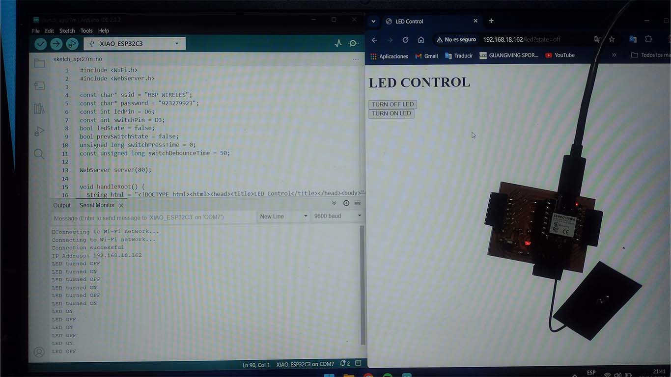
    PROGRAMMING

    Since it is a single board, we will only have one programming code to ensure that via WiFi we can turn the LED on the board on and off. Here is the programming code for ARDUINO IDE, remember to increase < > in the libraries.

                                
                                    #include WiFi.h
                                        #include WebServer.h
                                        
                                        const char* ssid = "HBP WIRELES";
                                        const char* password = "923279923";
                                        const int ledPin = D6;
                                        const int switchPin = D3;
                                        bool ledState = false;
                                        bool prevSwitchState = false;
                                        unsigned long switchPressTime = 0;
                                        const unsigned long switchDebounceTime = 50;
                                        
                                        WebServer server(80);
                                        
                                        void handleRoot() {
                                          String html = "LED Control";
                                          html += "h1>LED CONTROL";
                                          html += "form action=\"/led\" method=\"get\">";
                                          html += "button name=\"state\" value=\"on\" type=\"submit\">TURN ON LED";
                                          html += "/form>";
                                          html += "form action=\"/led\" method=\"get\">";
                                          html += "button name=\"state\" value=\"off\" type=\"submit\">TURN OFF LED";
                                          html += "/form>";
                                          html += "/body>";
                                          server.send(200, "text/html", html);
                                        }
                                        
                                        void handleLED() {
                                          String state = server.arg("state");
                                        
                                          if (state == "on") {
                                            digitalWrite(ledPin, LOW);
                                            ledState = true;
                                            Serial.println("LED turned ON");
                                          } else if (state == "off") {
                                            digitalWrite(ledPin, HIGH);
                                            ledState = false;
                                            Serial.println("LED turned OFF");
                                          }
                                        
                                          handleRoot();
                                        }
                                        
                                        void setup() {
                                          pinMode(ledPin, OUTPUT);
                                          pinMode(switchPin, INPUT_PULLUP); // Configure D3 as input with internal pull-up resistor
                                          digitalWrite(ledPin, HIGH);
                                        
                                          Serial.begin(115200);
                                          WiFi.begin(ssid, password);
                                        
                                          while (WiFi.status() != WL_CONNECTED) {
                                            delay(1000);
                                            Serial.println("Connecting to Wi-Fi network...");
                                          }
                                        
                                          Serial.println("Connection successful");
                                          Serial.print("IP Address: ");
                                          Serial.println(WiFi.localIP());
                                        
                                          server.on("/", HTTP_GET, handleRoot);
                                          server.on("/led", HTTP_GET, handleLED);
                                        
                                          server.begin();
                                        }
                                        
                                        void loop() {
                                          server.handleClient();
                                          
                                          // Check if the physical switch is pressed and toggle the LED accordingly
                                          bool switchState = digitalRead(switchPin);
                                          if (switchState != prevSwitchState) {
                                            if (switchState == LOW) {
                                              switchPressTime = millis();
                                            } else {
                                              unsigned long switchReleaseTime = millis();
                                              if (switchReleaseTime - switchPressTime >= switchDebounceTime) {
                                                digitalWrite(ledPin, !ledState);
                                                ledState = !ledState;
                                                if (ledState) {
                                                  Serial.println("LED turned ON");
                                                } else {
                                                  Serial.println("LED turned OFF");
                                                }
                                              }
                                            }
                                            prevSwitchState = switchState;
                                          }
                                        }


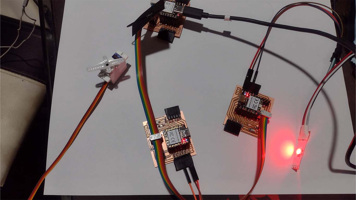
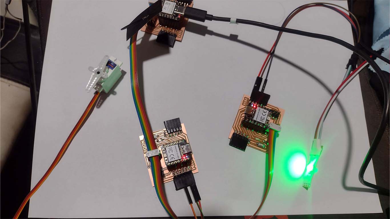
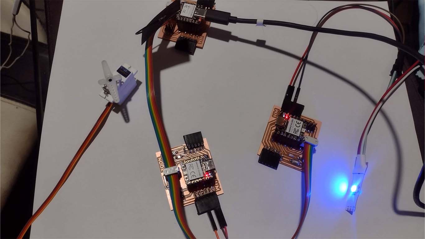
    WIFI + SERVO MOTOR + NEOPIXEL

    The last test I did is trying to synchronize a servo motor with a neopixel, where according to the angle that the servo motor moved, the neopixel took on a different color. All this controlled via WIFI where by pressing buttons on the computer, it changed color and angle. Here the process.
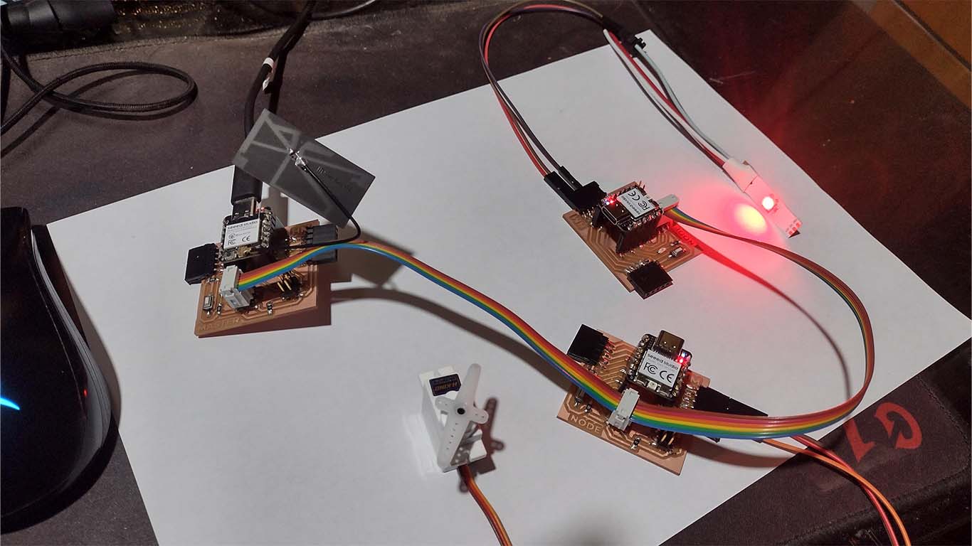
    PROGRAMMING

    For this case we need to program the 3 boards, the master where the XIAO ESP32 C3 is, which is the one that will connect via WIFI. Then NODE 1, which is where the Servo motor is located, and in node 2, the neopixel. Don't forget the < > signs for libraries.

    MASTER BOARD

                                    
                                        #include WiFi.h>
                                            #include WebServer.h>
                                            #include Wire.h>
                                            
                                            const char* ssid = "HBP WIRELES";
                                            const char* password = "923279923";
                                            const int RP2040_Servo_Address = 0x08; // Address of RP2040 slave for servo
                                            const int RP2040_Neopixel_Address = 0x09; // Address of RP2040 slave for Neopixel
                                            
                                            WebServer server(80);
                                            
                                            void handleRoot() {
                                              String html = "";
                                              html += "h1>SERVO CONTROL";
                                              html += "form action=\"/servo\" method=\"get\">";
                                              html += "button name=\"angle\" value=\"0\" type=\"submit\">0 degrees";
                                              html += "button name=\"angle\" value=\"90\" type=\"submit\">90 degrees";
                                              html += "button name=\"angle\" value=\"180\" type=\"submit\">180 degrees";
                                              html += "/form>";
                                              server.send(200, "text/html", html);
                                            }
                                            
                                            void handleServo() {
                                              int angle = server.arg("angle").toInt();
                                              Wire.beginTransmission(RP2040_Servo_Address);
                                              Wire.write(angle);
                                              Wire.endTransmission();
                                              Wire.beginTransmission(RP2040_Neopixel_Address);
                                              Wire.write(angle);
                                              Wire.endTransmission();
                                              delay(500); // Wait to allow the servo to fully move
                                              handleRoot();
                                            }
                                            
                                            void setup() {
                                              Serial.begin(115200);
                                              Wire.begin(); // Start I2C communication as master
                                              WiFi.begin(ssid, password);
                                            
                                              while (WiFi.status() != WL_CONNECTED) {
                                                delay(1000);
                                                Serial.println("Connecting to Wi-Fi network...");
                                              }
                                            
                                              Serial.println("Connection successful");
                                              Serial.print("IP Address: ");
                                              Serial.println(WiFi.localIP());
                                            
                                              server.on("/", HTTP_GET, handleRoot);
                                              server.on("/servo", HTTP_GET, handleServo);
                                            
                                              server.begin();
                                            }
                                            
                                            void loop() {
                                              server.handleClient();
                                            }


    BOARD NODE 1 - SERVO MOTOR

                                    
                                        #include Wire.h
                                            #include Servo.h
                                            
                                            const int SERVO_PIN = 2; // Pin connected to the servo
                                            
                                            Servo servo;
                                            
                                            void receiveEvent(int byteCount) {
                                              int angle = Wire.read();
                                              servo.write(angle);
                                            }
                                            
                                            void setup() {
                                              Wire.begin(0x08); // Address of RP2040 slave in I2C communication
                                              Wire.onReceive(receiveEvent); // Set up the data reception function
                                              servo.attach(SERVO_PIN); // Assign the pin to the servo
                                            }
                                            
                                            void loop() {
                                              // There's no need to do anything in the main loop
                                            }


    BOARD NODE 2 - NEOPIXEL

                                    
                                        #include Wire.h
                                            #include Adafruit_NeoPixel.h
                                            
                                            const int NEOPIXEL_PIN = 3; // Pin connected to the Neopixel
                                            const int NUM_PIXELS = 1; // Number of pixels in the Neopixel
                                            Adafruit_NeoPixel pixels(NUM_PIXELS, NEOPIXEL_PIN, NEO_GRB + NEO_KHZ800);
                                            
                                            void receiveEvent(int byteCount) {
                                              int angle = Wire.read();
                                              uint32_t color = getColor(angle);
                                              pixels.clear();
                                              pixels.setPixelColor(0, color);
                                              pixels.show();
                                            }
                                            
                                            uint32_t getColor(int angle) {
                                              if (angle == 0) {
                                                return pixels.Color(255, 0, 0); // Red
                                              } else if (angle == 90) {
                                                return pixels.Color(0, 255, 0); // Green
                                              } else if (angle == 180) {
                                                return pixels.Color(0, 0, 255); // Blue
                                              } else {
                                                return pixels.Color(255, 255, 255); // White if angle is not defined
                                              }
                                            }
                                            
                                            void setup() {
                                              Wire.begin(0x09); // Address of RP2040 slave in I2C communication
                                              Wire.onReceive(receiveEvent); // Set up the data reception function
                                              pixels.begin(); // Initialize Neopixel
                                              pixels.clear();
                                              pixels.show(); // Turn off all pixels
                                            }
                                            
                                            void loop() {
                                              // There's no need to do anything in the main loop
                                            }


    RESULT

    First we look at the IP that the microcontroller gives us to be able to change the angle of the servomotor. Here is a screenshot of the programming and the buttons generated for the movement.

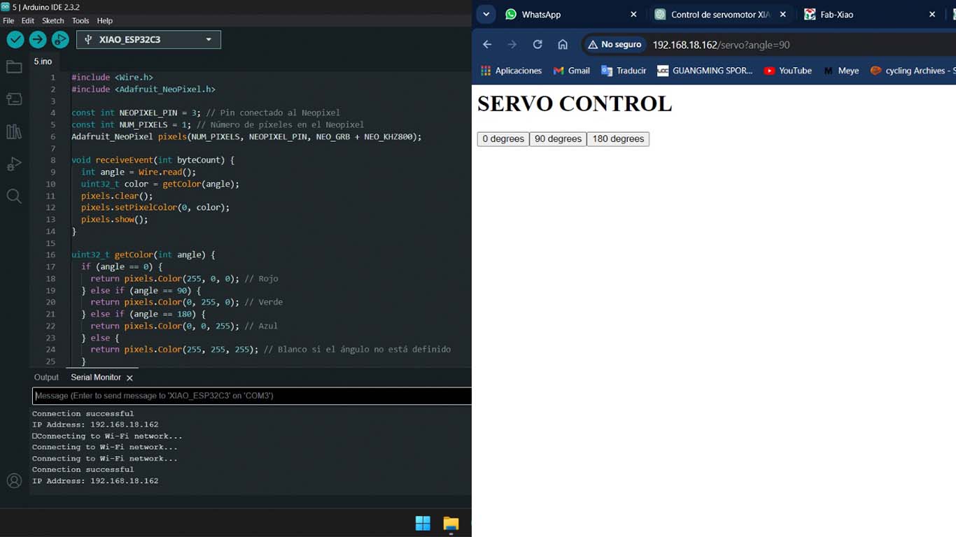
    As a result we can see that the angle and color synchronization work. The red color of the neopixel means 0°, the green color means 90° and finally the blue color means 180°. Here are some photographs and video

    CONCLUSIONS

    This week's assignment has been very difficult for me because at first it was complicated and I didn't understand where to start and how to achieve the assignment. OPEN GLOBAL TIME and my advisor Ulysses helped me a lot and I thank him for supporting me in this assignment. In conclusion I can say that I2C programming seems better to me, it is easier than doing it through UART. I tried to do this last communication protocol but it didn't work for me. But it is a week where you learn much more and the truth is that it was difficult and challenging for me. In the end, here I show you what I achieved.

    REVIEW OF THE CLASS

    During the review of this class I volunteered in the minute 1:23:30

    Clic here to 20240424 review from Academany on Vimeo.

    FILES

    Here you can download all the files that I have made for the following assignment:

  • HM MASTER.RAR
  • HM NODE.RAR
  • LEARNED

  • This week I learned how to develop communication between microcontrollers. I had never done it and during the FAB ACADEMY I didn't think it could be possible either, I learned a lot about communication and the ways to achieve it.
  • I learned to program microcontrollers using WIFI, know about communication protocols and also servers that allow us to communicate with our microcontrollers over the Internet. A new and very interesting world from my perspective.
  • I learned about UART and I2C communications, each one has its own ways of working and the truth is that I find them very interesting and at the same time complicated because you have to be patient and discover the error in steps. A lot of stress but a lot of learning.
  • I learned that the PINS and the datasheet of the microcontrollers are important to know, their function and what each one of them does because we must take into account all the characteristics and for this week mainly the communication pins that are important to achieve many things.
  • TO TAKE INTO ACCOUNT

  • For this week I would recommend that you should take into account the design of your development boards, sometimes we design unconsciously but the distribution of the PINS and what each one of them is and what they are for is important.
  • We must take into account the communication protocol that we are going to use for the assignment and for the different projects that we can develop. It is important to know the characteristics they offer us.
  • We must take into account that to achieve the communication of boards or microcontrollers we must exhaustively evaluate each component because sometimes the failures can be both physical and soldering and continuity of components and on the other hand programming, if we go step by step we can find the error .
  • Finally, we must take into account the configurations that we must have to achieve communication between boards because each type and shape are different.
  • LINKS