This week's assignment was:
- Review the safety data sheets for each of your molding and casting materials, then make and compare test casts with each of them compare printing vs machining molds
- Design a mold around the process you'll be using, produce it with a smooth surface finish, and use it to cast parts
- EXTRACREDIT: Use more then two mold parts
ORGANIZATION
Here I show how I organized myself for this week.
| Wednesday 17th: | Fab Academy classes, organization for the week and review of all materials and supplies available for the assignment. |
|---|---|
| Thursday 18th: | Review and investigation of previous documentation to understand the orders and design of my model for the mold. |
| Friday 19th: | Milling and 3D printing of my model. Detection of errors to achieve the assignment. |
| Saturday 19th: | Enter GLOBAL OPEN TIME and develop the group assignment with my colleagues. |
| Sunday: 20th: | Carry out documentation of everything developed. |
| Monday 21th: | Review and correction of documentation. Update and changes for last commit. |
| Tuesday 22th: | Documentation and last commit of the week. |
GROUP ASSIGNMENT
Here I leave the link to go to the group assignments page.
Clic here to visit the WEEK 12 GROUP ASSIGNMENT PAGE
REVIEW THE SAFETY DATA SHEETS FOR MATERIALS
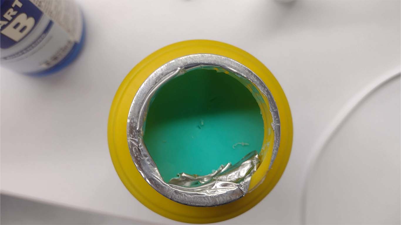
SILICON OMMO 25 - SMOOTH ON
For the group order, I have a little anecdote - a problem we had. We are confident because in the UCSUR fab lab we have the OMMO 25 silicone from SMOOTH - ON. Confident that we had approximately more than 15 lots of the product, we let the day pass because on Saturday we were going to do the group work. However, when the day arrived we checked the products that were stored and we could see that they were dry or expired. None were valid, mainly type A (yellow bottle) they were all dry. This is where the worry of the week began.
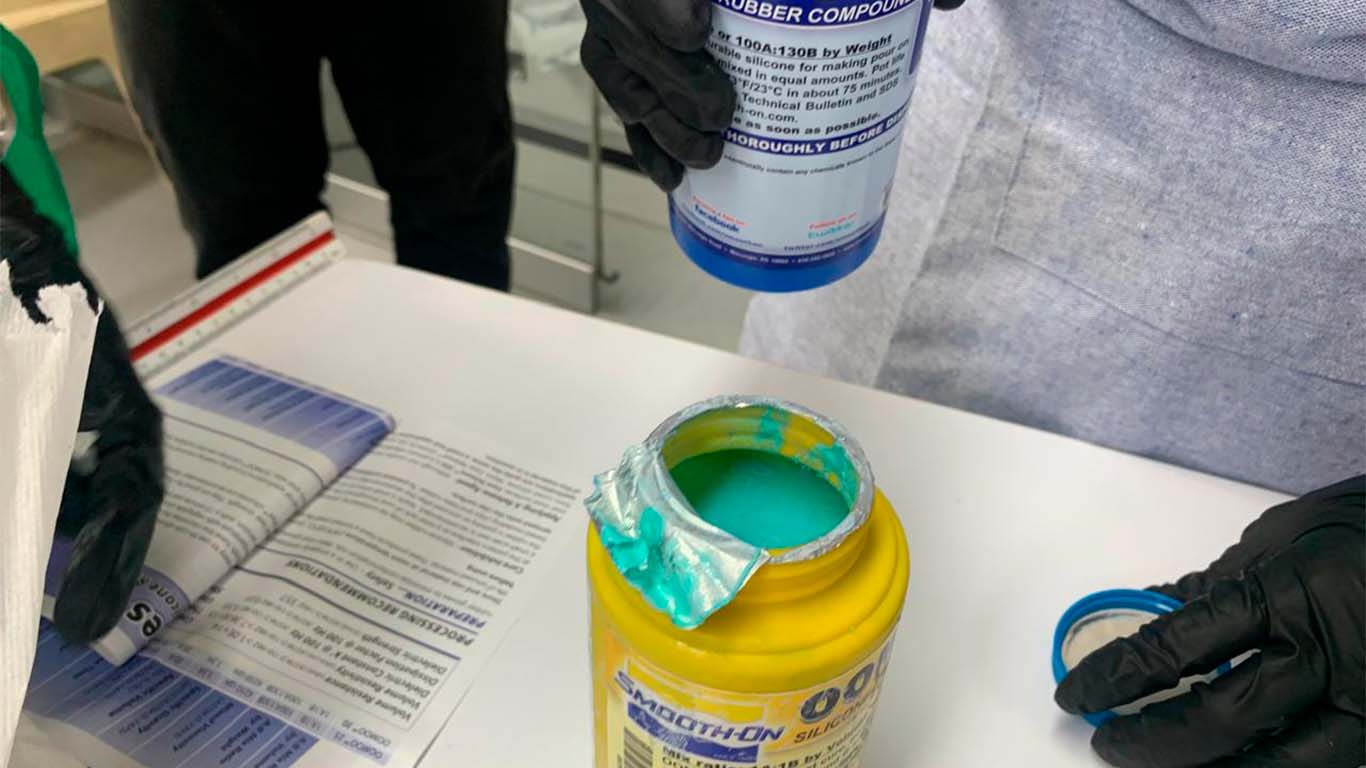
Here we can see how the product was. We don't know what happened to the material, maybe the storage time passed or they all arrived that way. Likewise, we read their data sheets to take it into account before April, but we were surprised by the following problem.
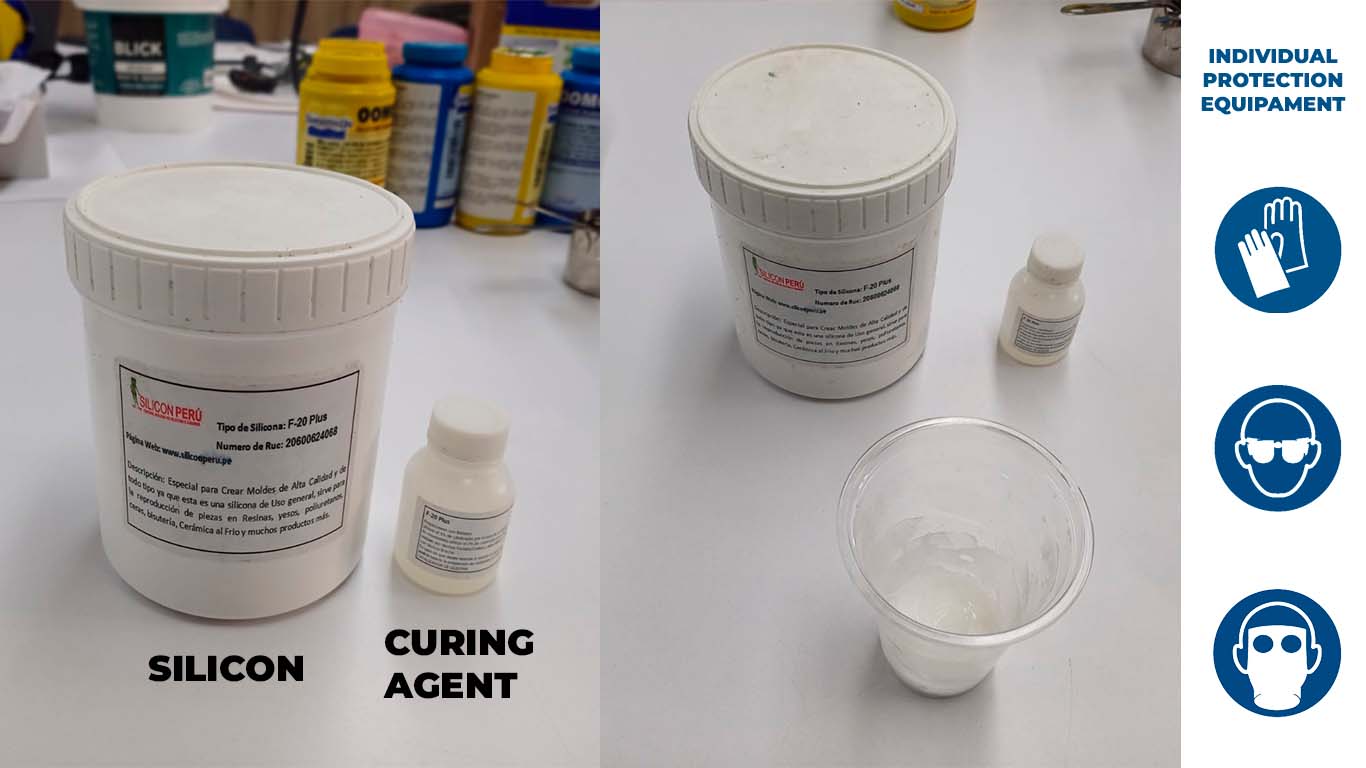
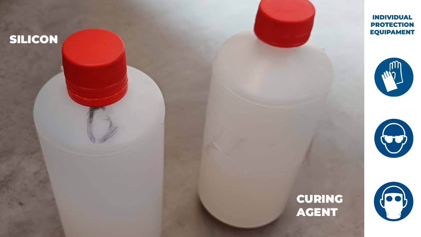
SILICON RTV F20 PLUS
The following silicone consists of 2 parts, a white liquid which is the silicone and the curing agent. Curing time is 4 to 8 hours. It has good tear resistance and excellent temperature resistance. Here is a summary table of the data sheets provided by the seller and the PDF to download.
| CARACTERISTIC | INSPECTION METHOD | VALUE |
|---|---|---|
| MIX RATIO | A:B | 100:3 |
| COLOR | - | white |
| POT LIFE | 25°C | 40-50 mins |
| Demold time | 25° C | 8-12h |
| Storage | Storage in cool dry places | - |
| Shelf life | - | 12 months with original unopened package |
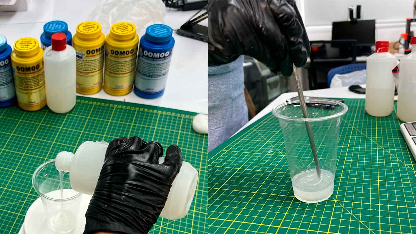
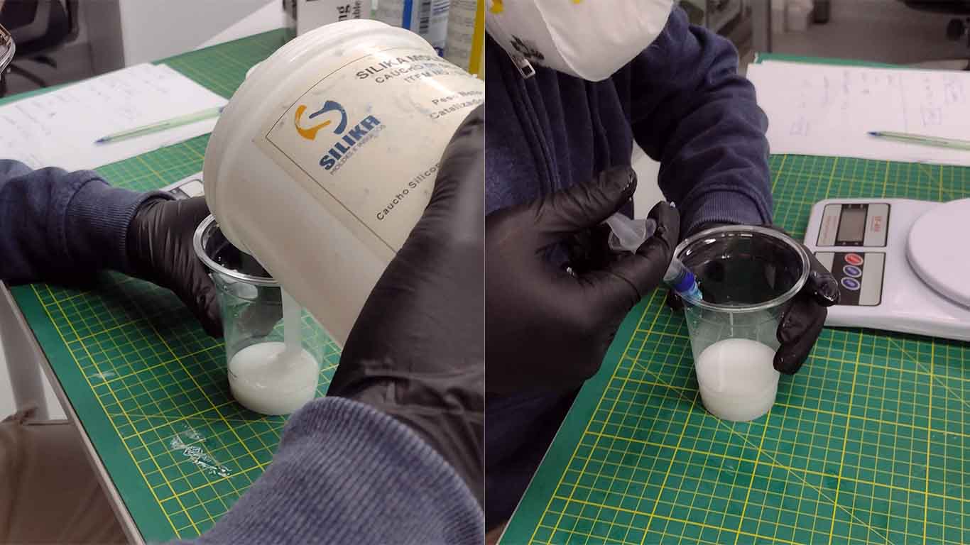
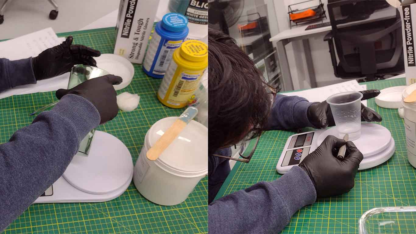
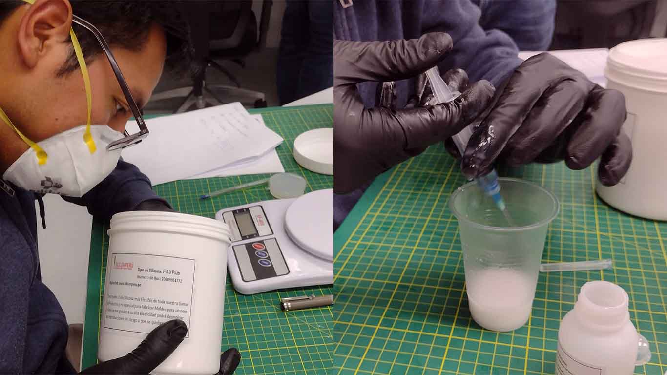
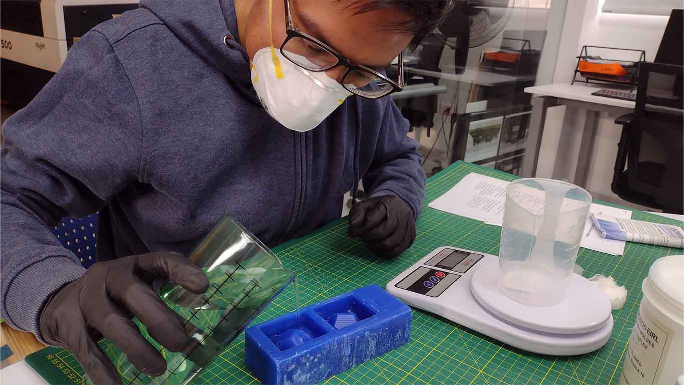
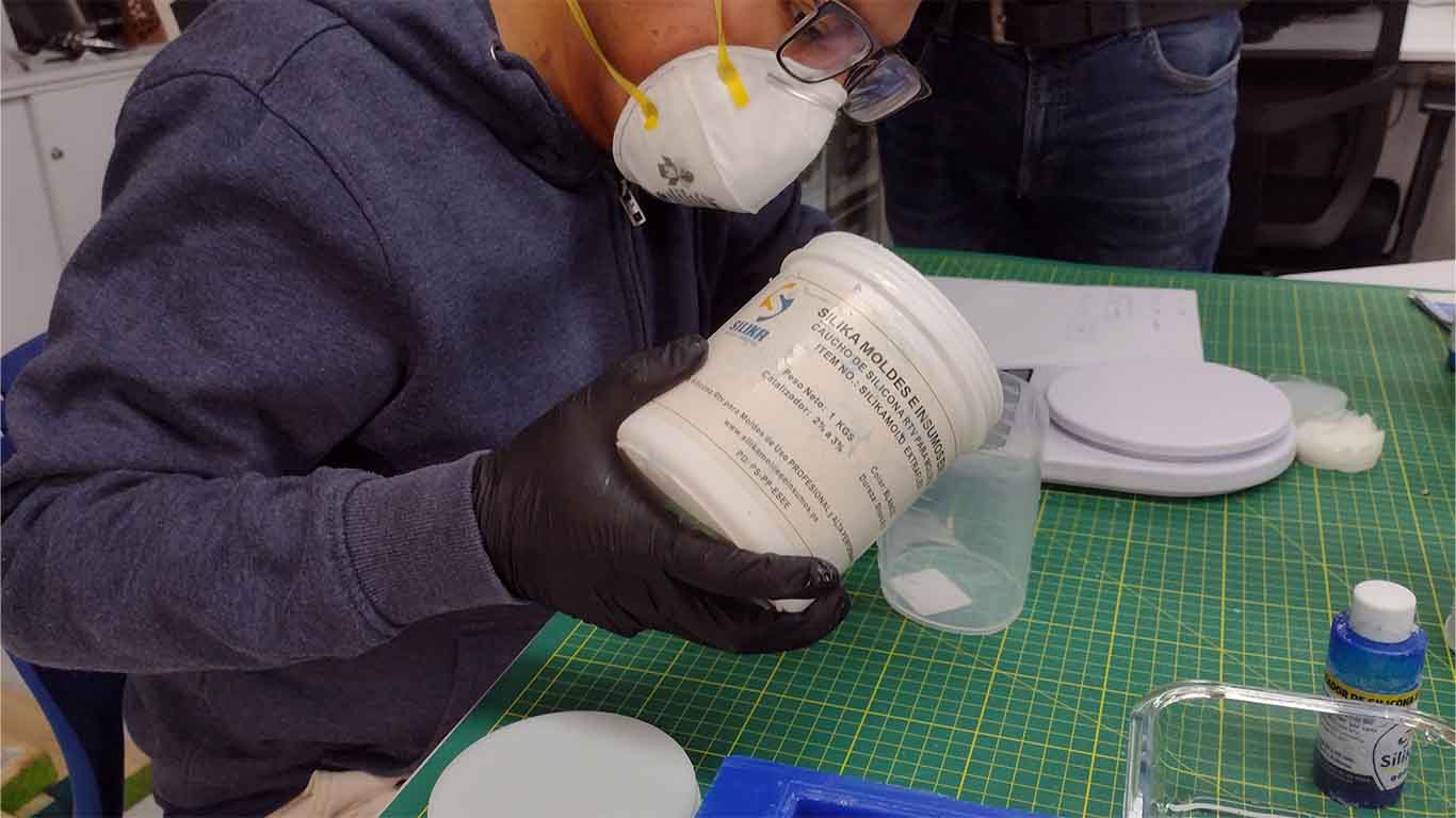
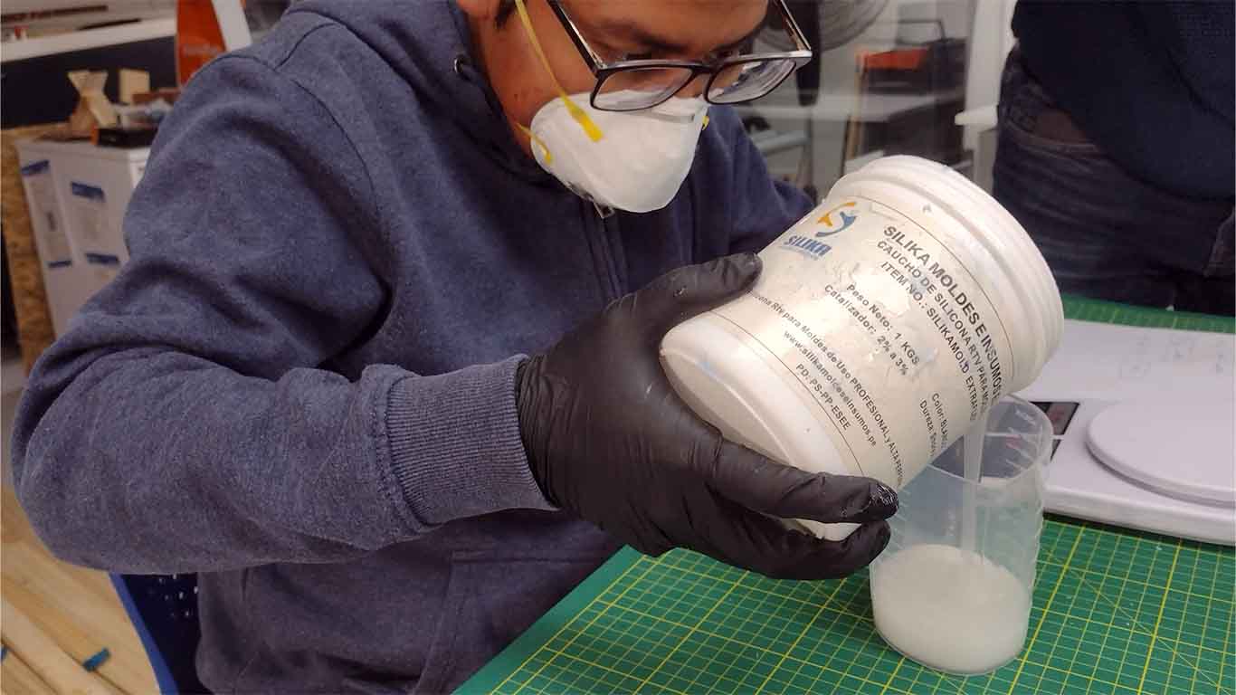
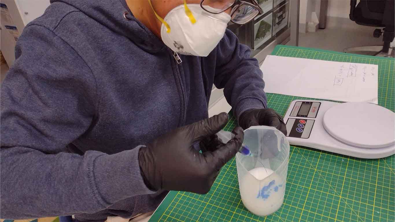
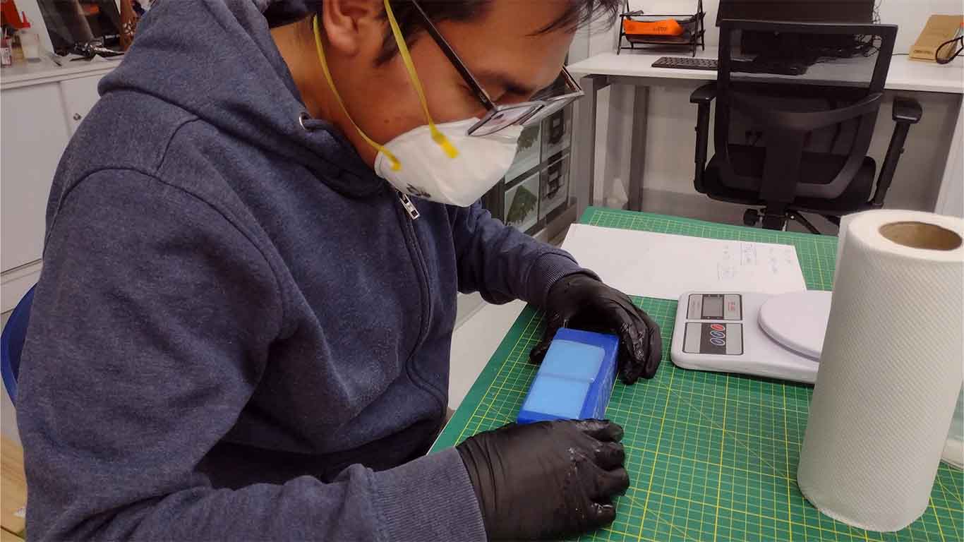
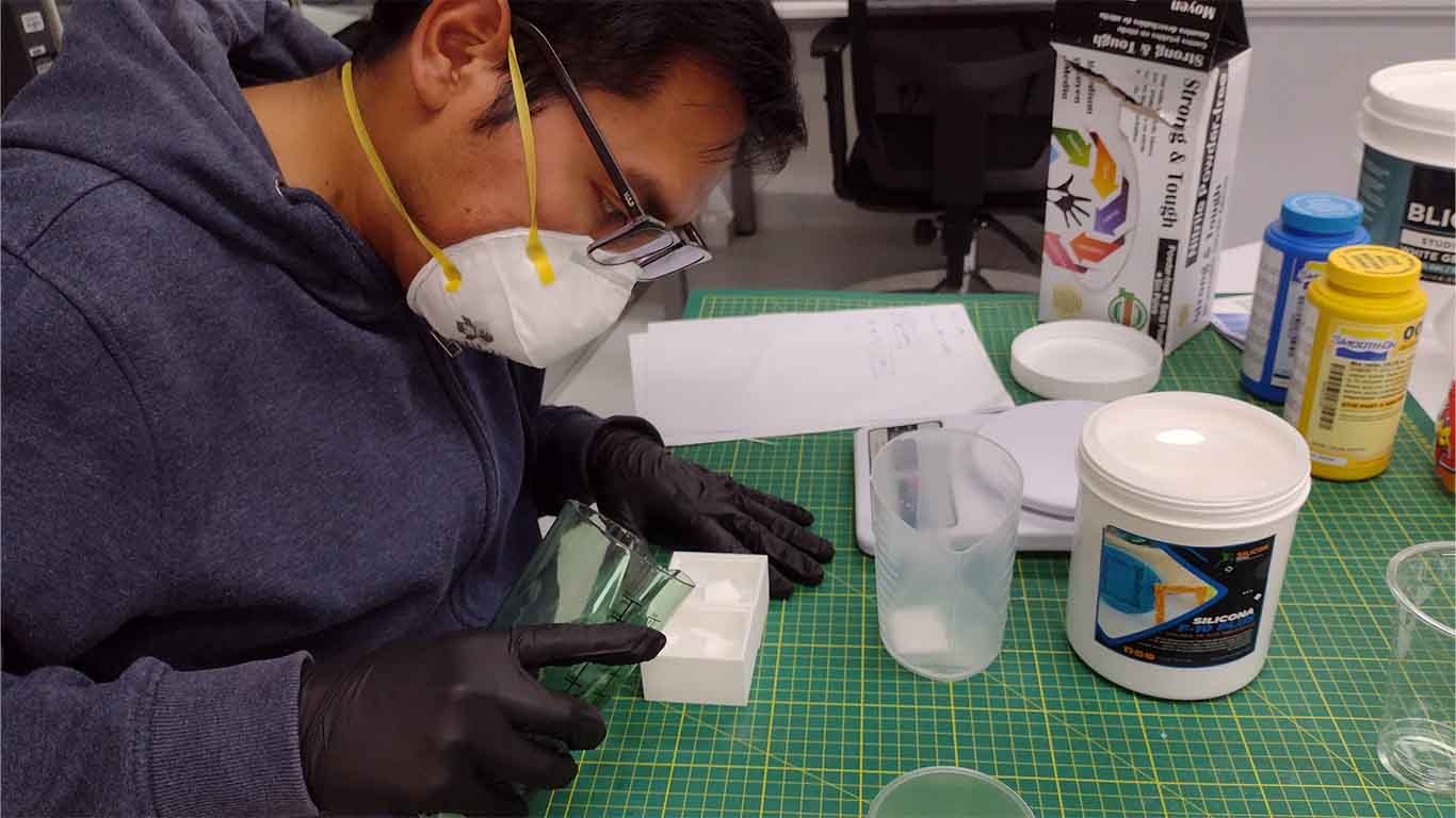
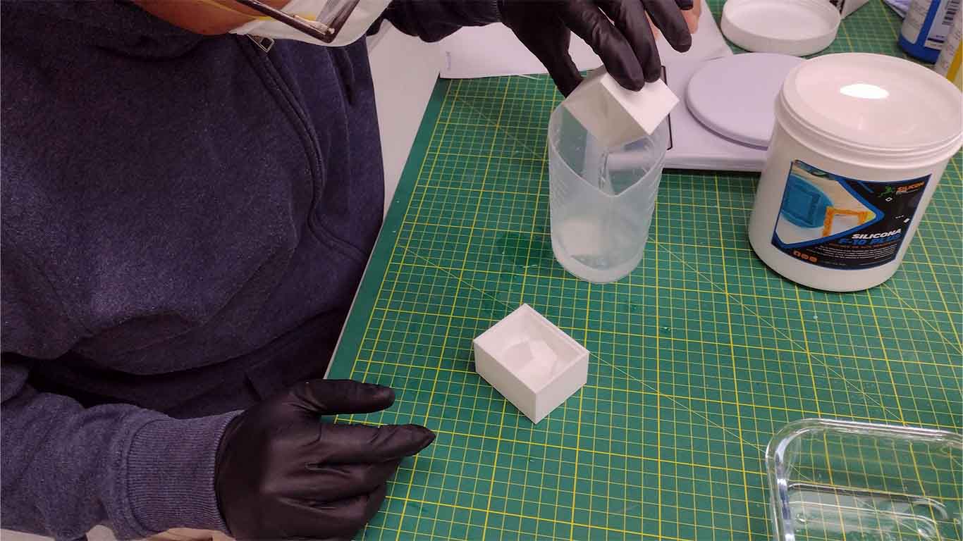
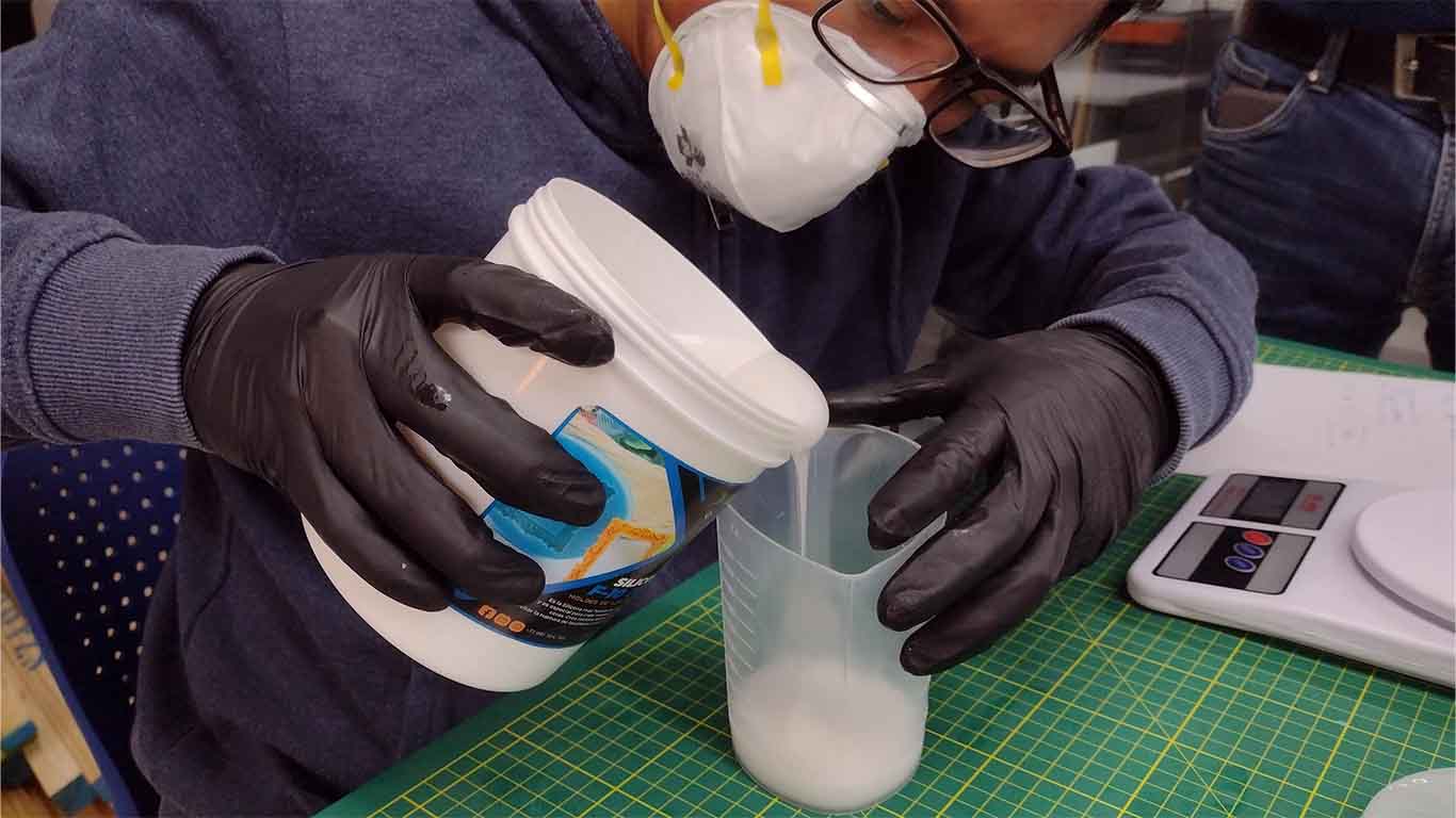
After reading the datasheets, we begin to use the material and mix according to the characteristics and values it provides us. Here is a photograph of the process and you must also take into account personal protective equipment since they are mandatory for the use of this material.
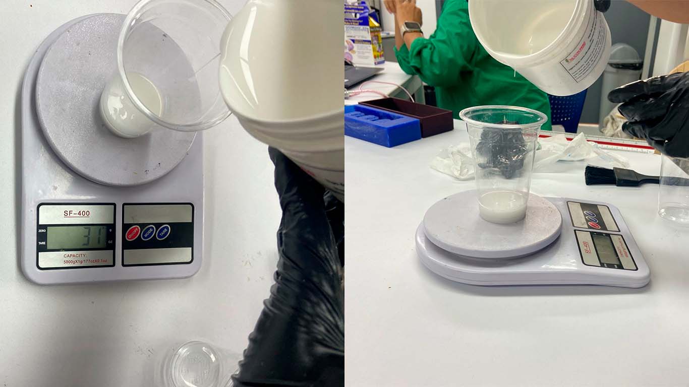
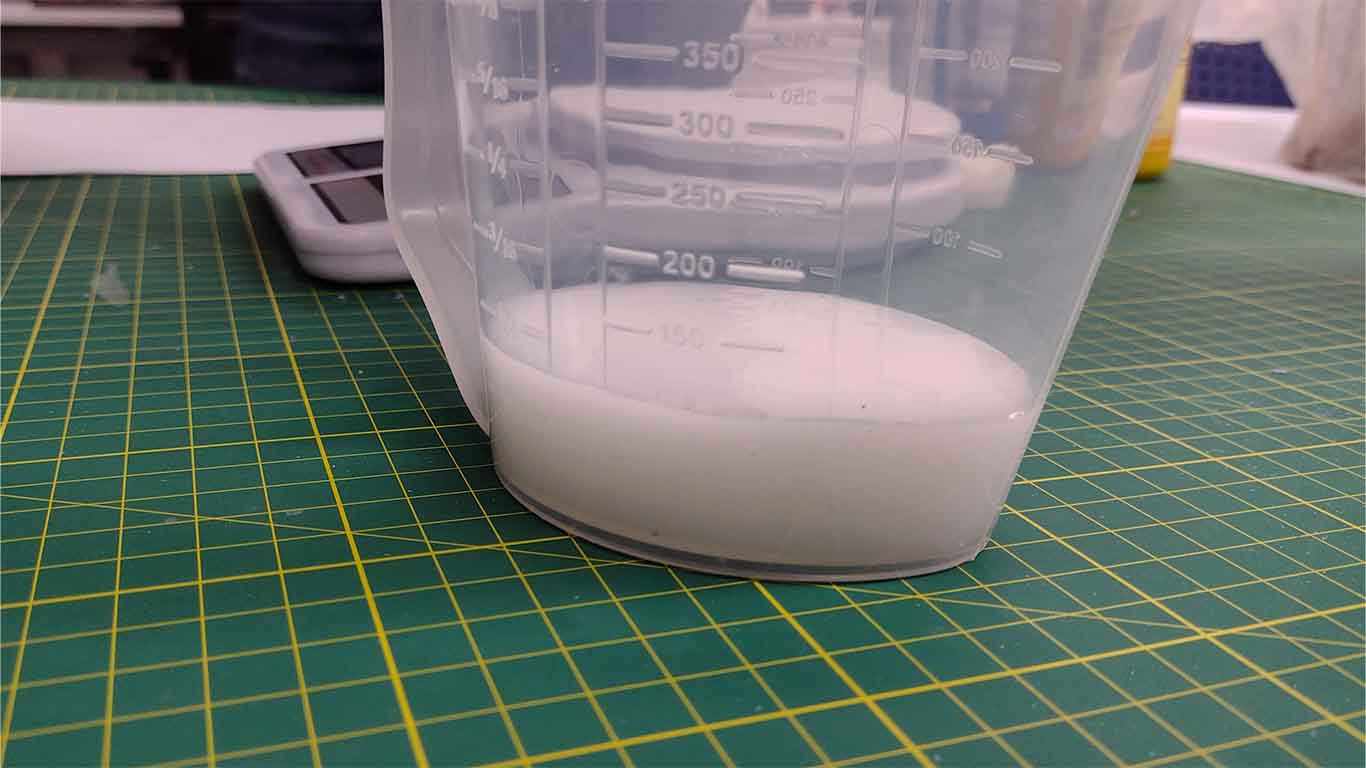
Then we started weighing to achieve the proper ratio between silicone and curing liquid according to the data sheets.
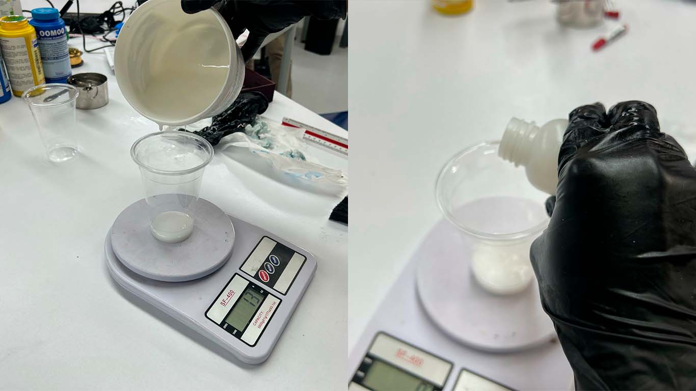
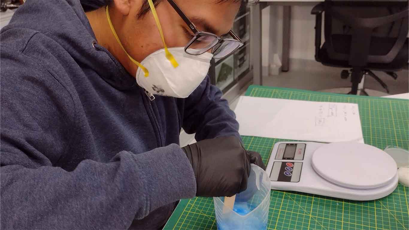
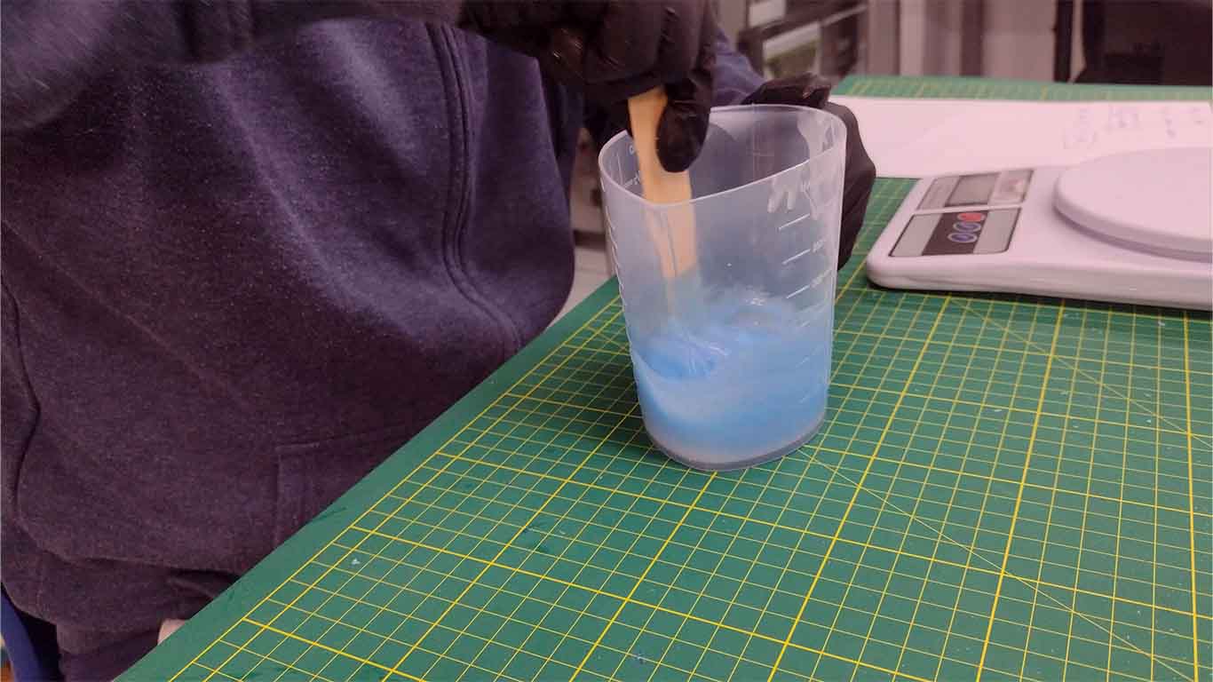
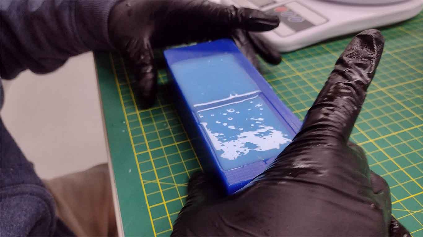
After combining both materials, we begin to move the mixture to obtain a uniform liquid to obtain the result of the silicone test.

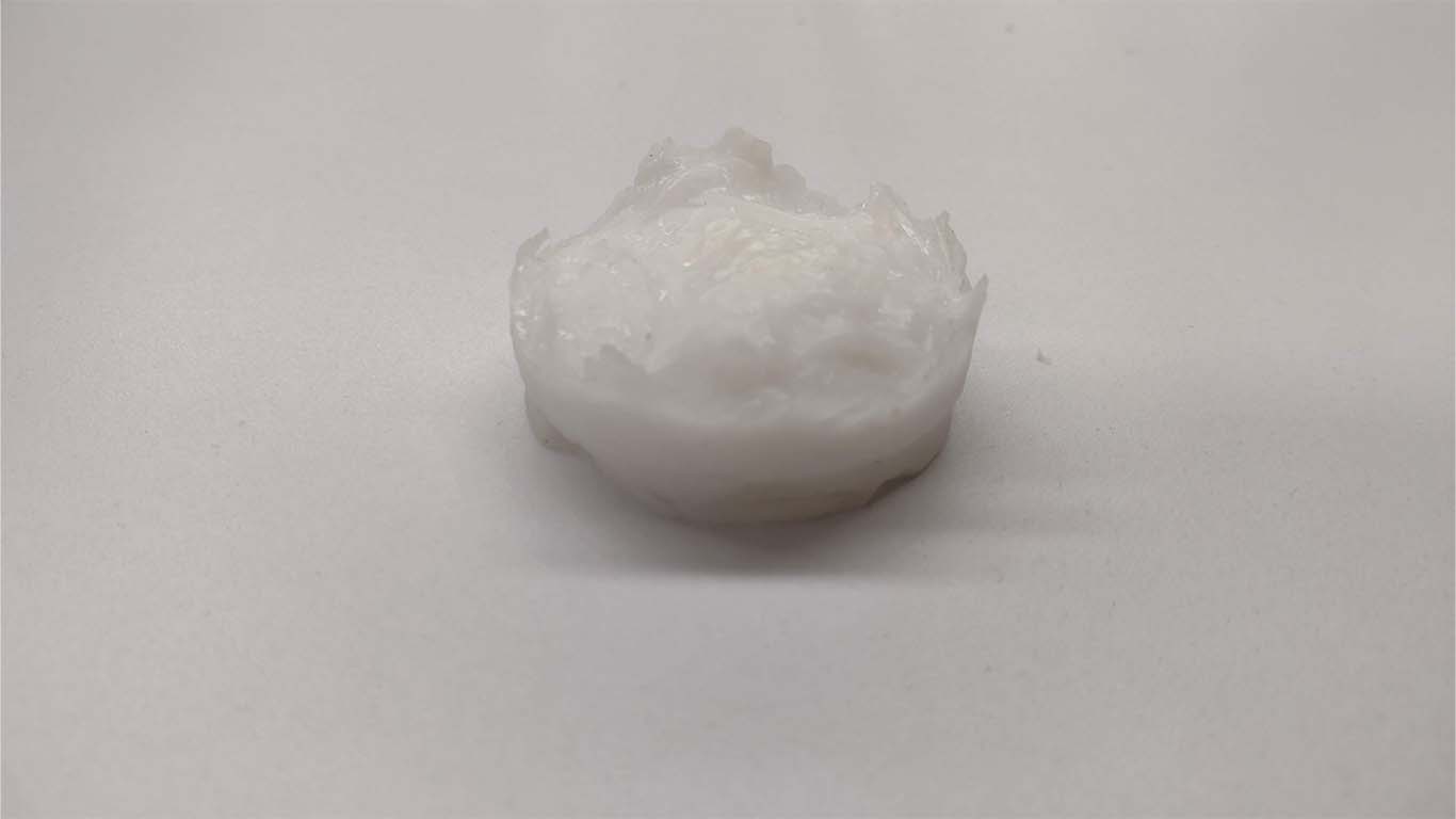
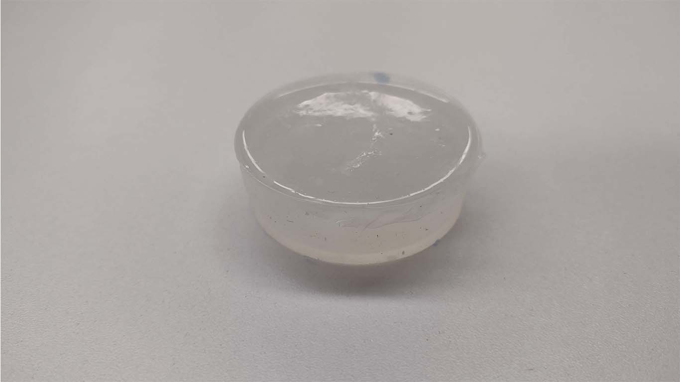
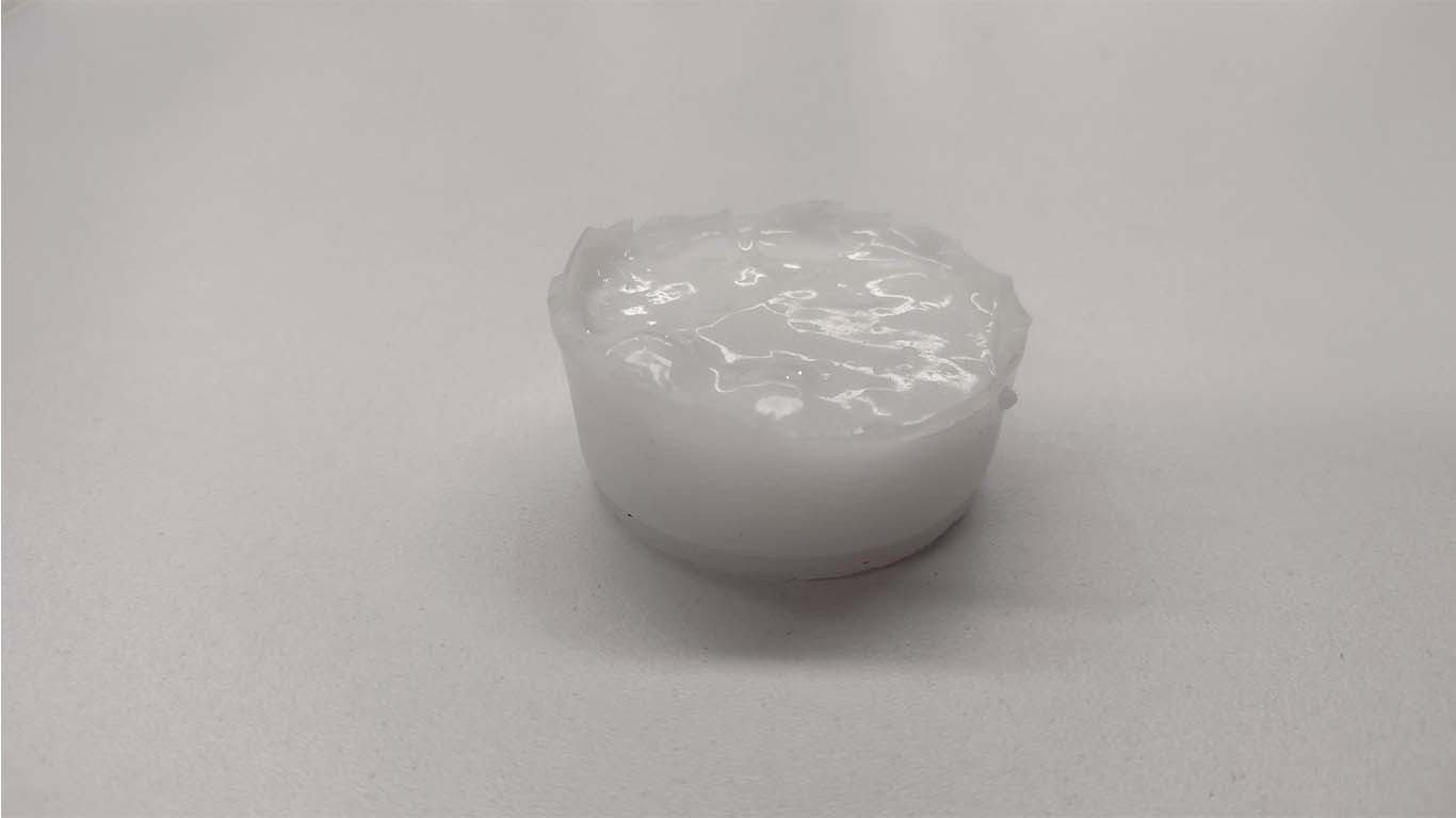
Finally, after waiting for about 8 hours, we were able to get the sample result. It turned out well because it resisted, we just needed to mix it better so that it could obtain the exact shape of the glass that we used as a mold.
PLATINUM RTV SILICONE HARDNESS 30-1 FOOD
The following silicone, similar to the previous one, also includes 2 mixtures. The main characteristic of silicone is that it is food grade, that is, we can use it to make molds for food, cakes or other types. It has high resistance to high temperatures and tearing. Here is a summary of its data sheet and also a PDF where all its technical specifications are found.
| CARACTERISTIC | INSPECTION METHOD | VALUE |
|---|---|---|
| MIX RATIO | A:B | 1:1 |
| COLOR | - | Translucent |
| POT LIFE | 25°C | 30-60 mins |
| Demold time | 25° C | 5-12h |
| Storage | Storage in cool dry places | - |
| Shelf life | - | 12 months with original unopened package |
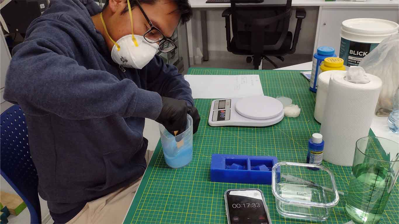
After reading the data sheets we did our test with the proportion we provided and mixed to obtain the result. Let's remember that the curing time is 5 to 12 hours. In addition, we have to keep in mind that the mixing time is 3 to 5 minutes maximum and then pour into our mold.
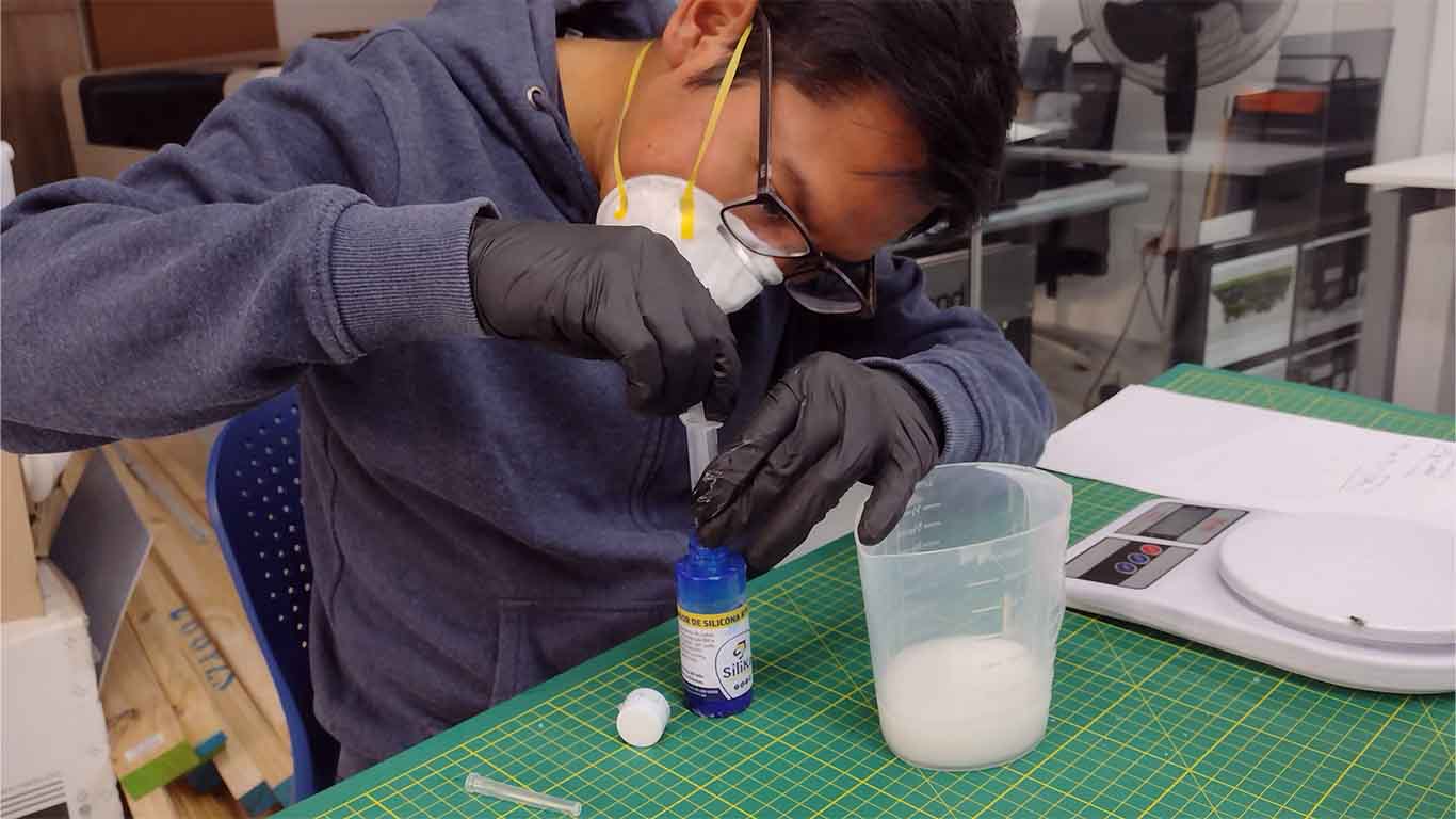
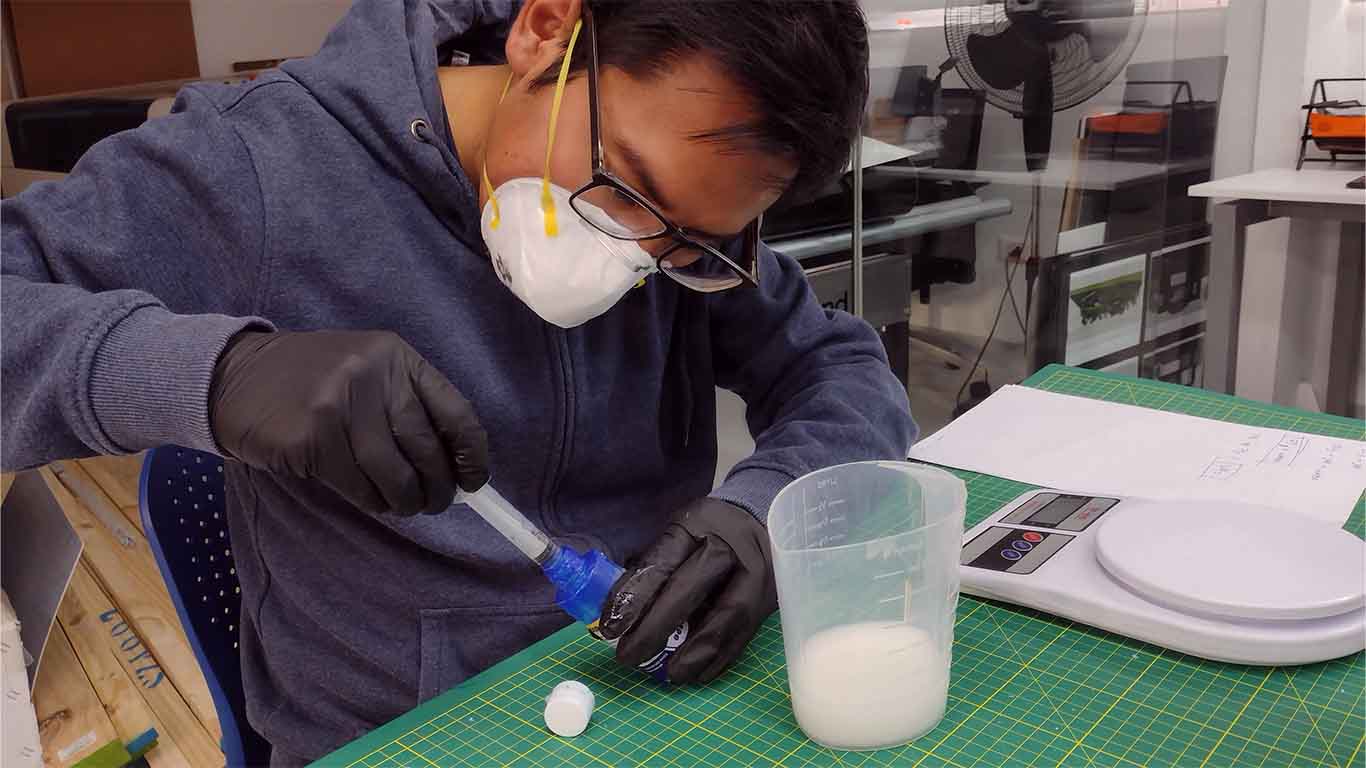
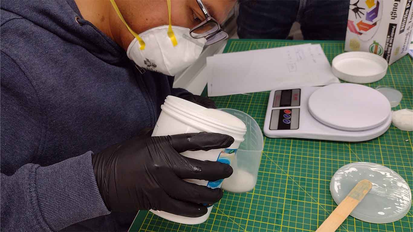
First we weigh our containers, then we weigh the exact amount for our test and begin to mix both components.
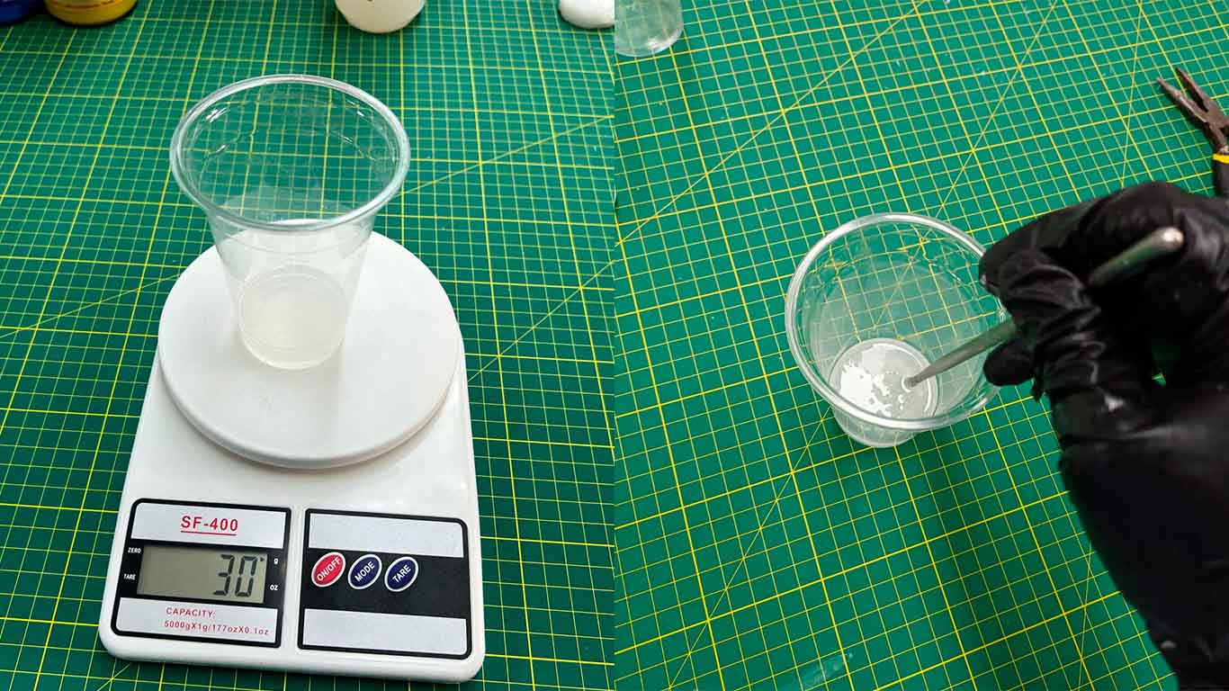
Finally, we add the necessary amount according to the amount mentioned in the technical specifications and begin to mix for 3 to 5 seconds to pour into the glass that we will use as a container.
After waiting the hour recommended by the supplier for the curing time, we were able to obtain the result. It came out very well, resistant and with better molding compared to the previous one.
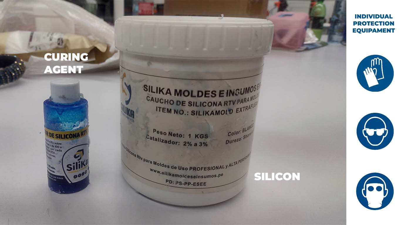
RTV EXTRAFLEX SILICONE RUBBER
The following silicone has extra flexibility that facilitates the removal of the inner mold, it is specifically intended for soaps, candles, among others. It comprises 2 products, silicone and silicone catalyst, which only uses 2% of the total amount of silicone used. Here is a summary table of the RTV EXTRAFLEX silicone data sheet.
| CARACTERISTIC | INSPECTION METHOD | VALUE |
|---|---|---|
| MIX RATIO | A:B | 100:2 |
| COLOR | - | White |
| POT LIFE | 25°C | 30-60 mins |
| Demold time | 27° C | 4-8h |
| Storage | Store covered, in a dry and cool place. | - |
| Shelf life | - | 12 months with original unopened package |
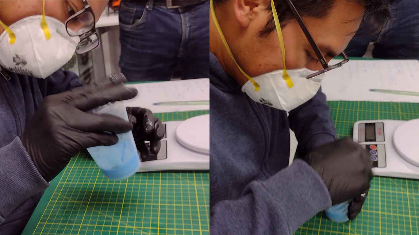
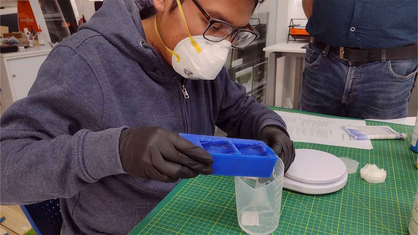
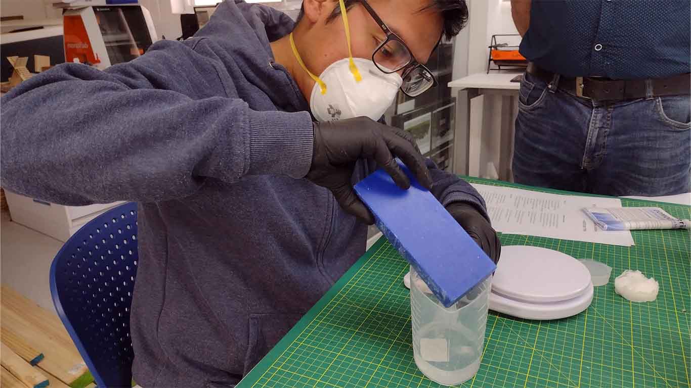
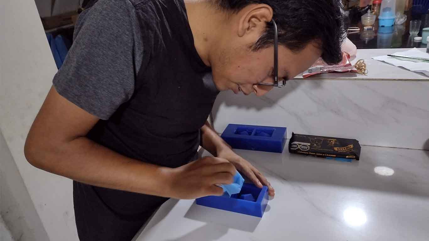
After understanding the proportion of silicone and catalyst as well as other aspects such as the security that we must have. We will proceed to carry out the test in a glass.
First we start by weighing our container for the test and then we do simple calculations to obtain the amount we will need. We can use water to have better precision.
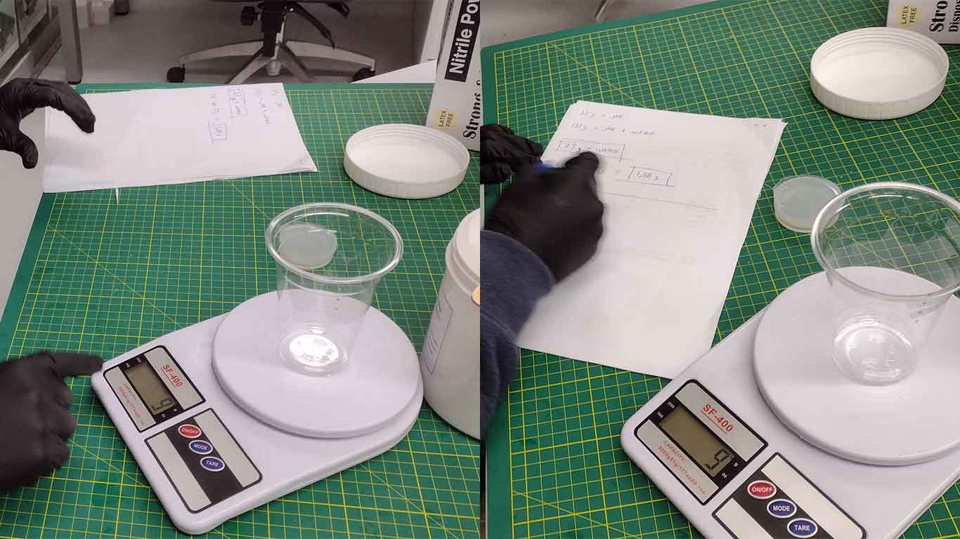
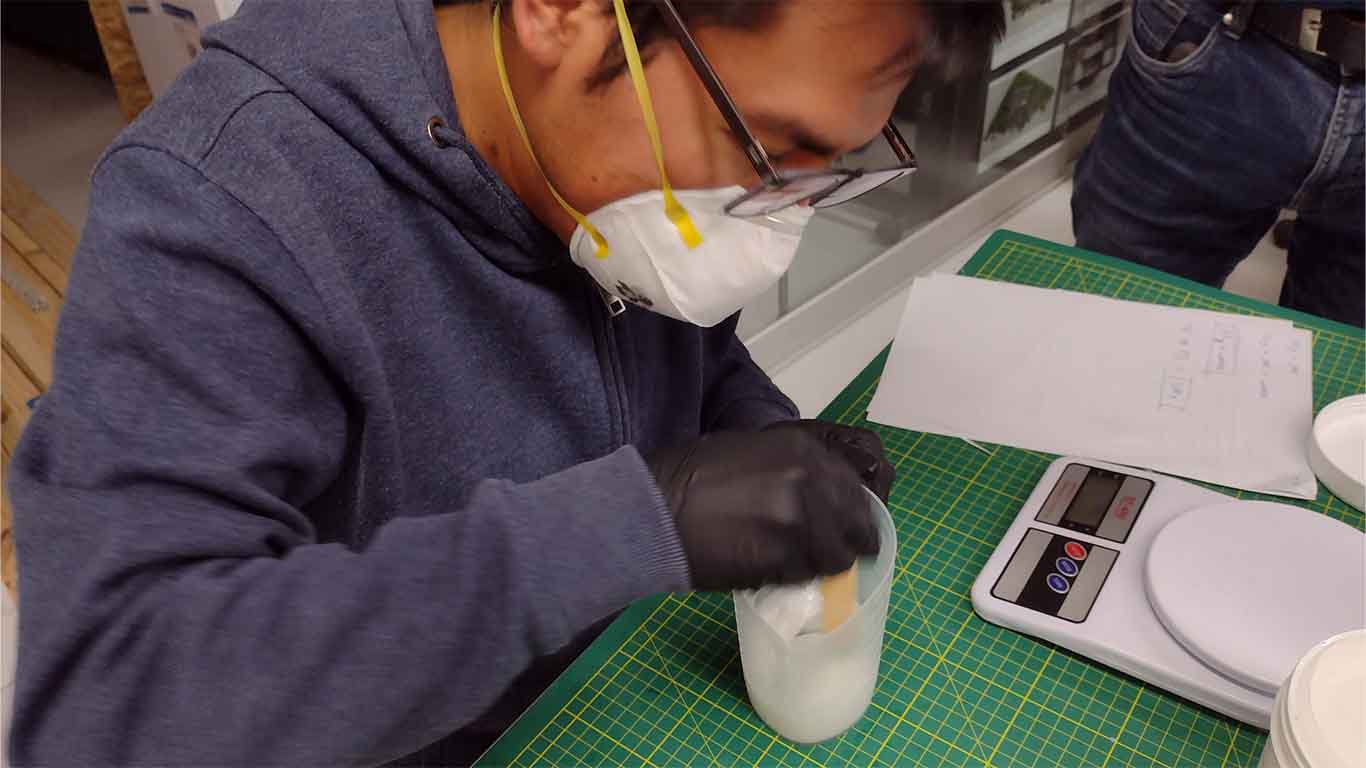
After having the quantities that we are going to need, we begin to mix the silicone with its catalyst. Let us always remember the proportion provided to us in the material data sheet.
Then we start mixing and moving to have a uniform mixture so that it can be contained in the mold and can enter all the details of the glass on that occasion.
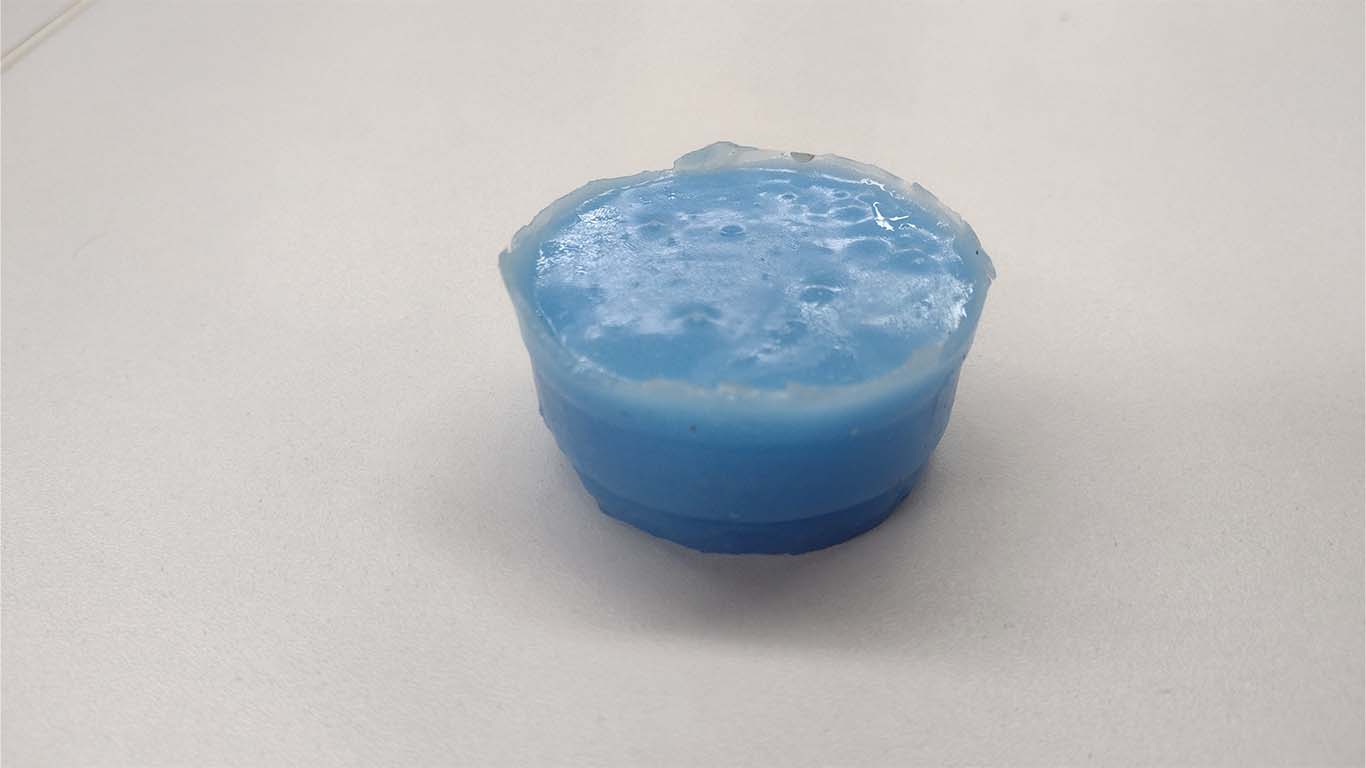
Finally, after obtaining the mixture and waiting approximately 8 hours after making the mixture. We can unmold and obtain the result. The silicone is very flexible and took the exact details of the packaging.
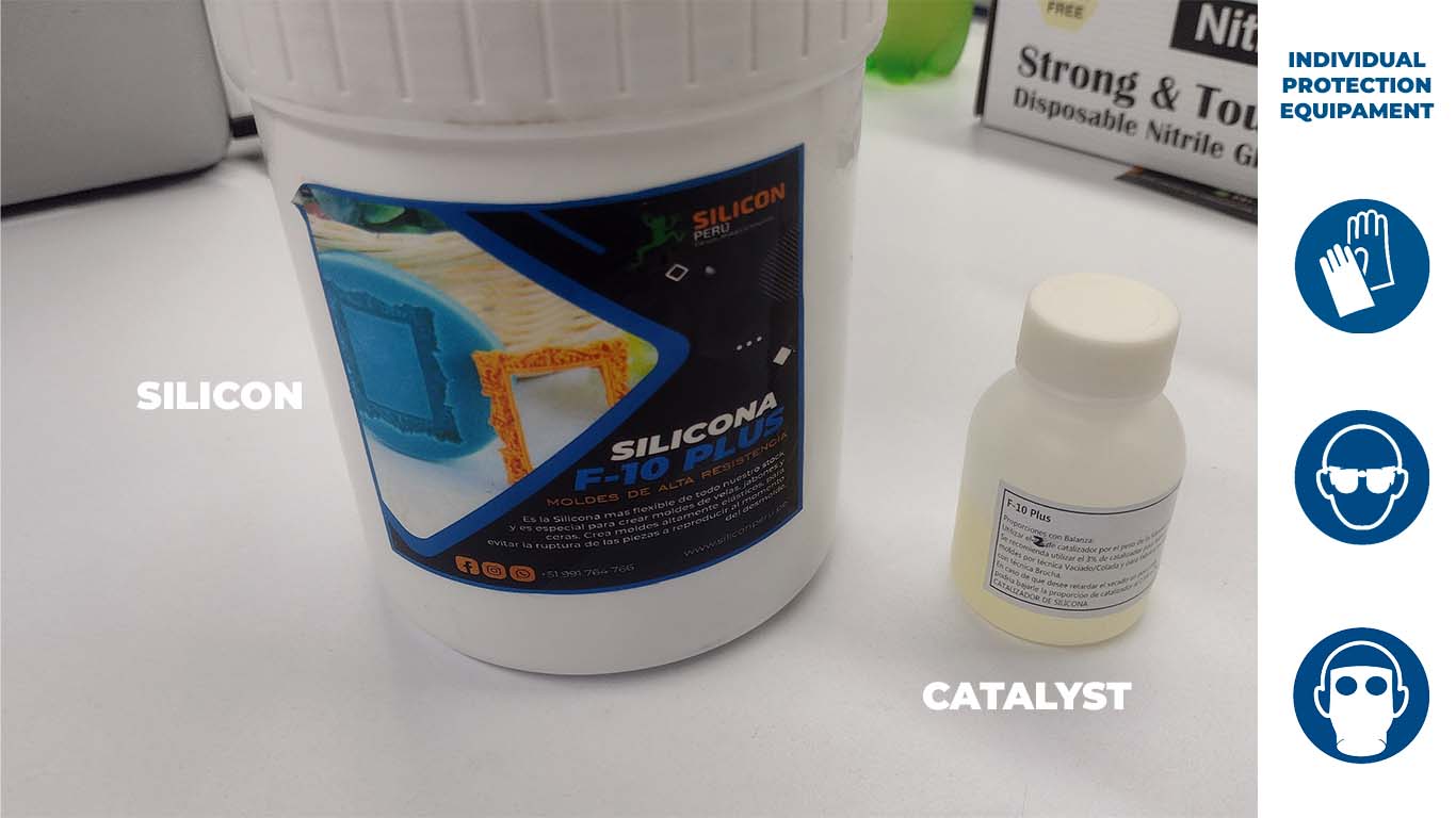
SILICON F10 PLUS
The following RTV F-10 silicone is a flexible silicone that is for creating elastic moles. It is resistant to breakage and is suitable for producing molds for wax, soap and candles. Here is the data sheet that the supplier gave us and a summary table of it.
| CARACTERISTIC | INSPECTION METHOD | VALUE |
|---|---|---|
| MIX RATIO | A:B | 100:3 |
| COLOR | - | White |
| POT LIFE | 25°C | 40-50 mins |
| Demold time | 27° C | 8-12h |
| Storage | Store covered, in a dry and cool place. | - |
| Shelf life | - | 12 months with original unopened package |
After understanding the curing time and the proportion that we have to take into account so that the silicone can become a mold, we will proceed to perform the test in a glass similar to the previous ones to know the consistency and curing time.
We began to make the exact measurements for the test and have the exact proportions and have a perfect mold. In this case we use water first to obtain the weight of how much silicone we are going to use.
After obtaining the indicated weights and the appropriate portions for the test, we begin to make the silicone in our glass and then the catalyst; the proportion according to the data sheet is 100 to 1, that is, for 100 ml of silicone, 3 ml of catalyst.
Finally, after carrying out the entire mixing process, we waited for the curing and after 24 hours we were able to obtain the following result.
COMPARATION AND CONCLUSION FOR SILICON TEST
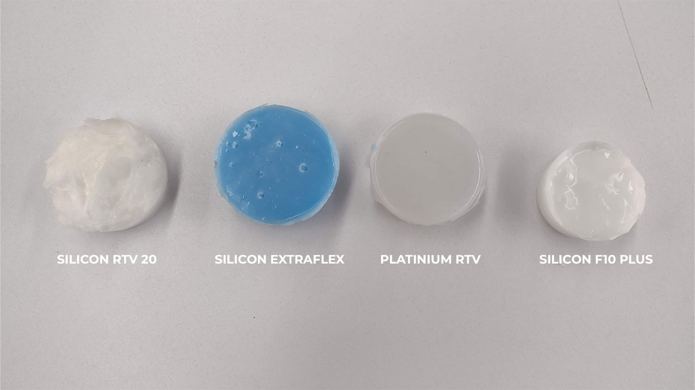
After carrying out all the tests on the silicones that we were able to obtain in Lima, Peru together with my colleagues. I can leave these 3 conclusions that I think are important in the following table:
| CHARACTERISTICS | RTV 20 | PLATINIUM RTV | EXTRAFLEX | F10 PLUS | CONCLUSION |
|---|---|---|---|---|---|
| DEMOLD TIME | 8-12h | 5-12h | 4-8h | 8-12h | Regarding time, I consider that Platinium silicone and Extraflex have a shorter curing time and the product is ready to use. |
| DESMOLDING | Little difficult | Difficult | Easy | Easy | Regarding demolding, I would recommend using the EXTRAFLEX and the F10 PLUS because being more flexible than the other two, we can obtain better molding. |
| DETAILS | little detail | detailed | Very detailed | Very detailed | According to the details, I consider that the F10, Platinium and Extraflex silicones present better detail of the mold we want to make. |
| FLEXIBILITY | flexible | not very flexible | very flexible | Very flexible | I consider that flexibility is important when making molds to be able to remove them and we only had complications with the PLATINIUM silicone |
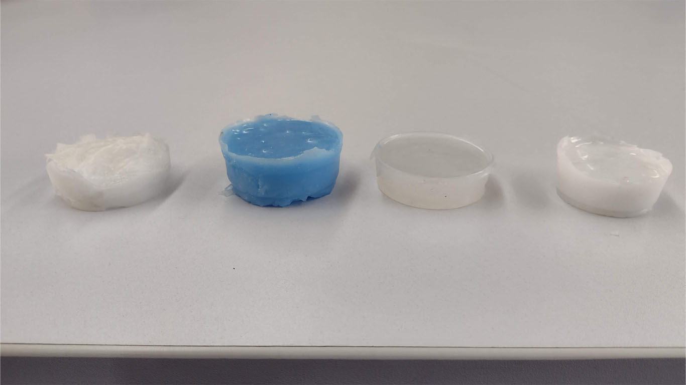
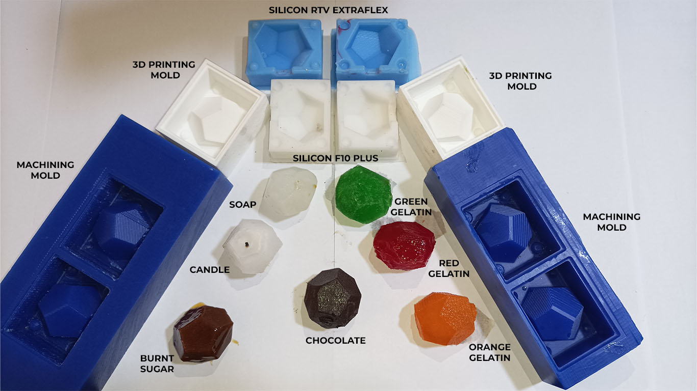
Here is a photograph of all our silicone tests that we did for the assignment.
COMPARATION PRINTING VS MACHINING MOLDS
To compare printing and machining molds, I think we have to see the process of each of them. 3D printing molds are faster to make and have a very detailed finish for casting. I consider that due to time and finish it is a good option to use. Compared to machine molds, we have to carry out a more laborious process of configurations and milling but it is not left behind in terms of finishes. Both have characteristics that distinguish them.
After seeing the molds of each process, I would choose the 3D printing mold because of the speed and detail we can achieve. I liked how to make molds with a machine and wax, but in my case, I suffered a lot in the machine configuration and finishing stage because I felt that the machine was uneven or the wax was not finishing in some areas of my model. I consider that the 3D mold obtains more detail from the model unlike the machine mold.

INDIVIDUAL ASSIGNMENT
DESIGN MY MOLD
For the next assignment I had doubts about what object I wanted to make. I had never made a mold and I had questions about what to do. I remember wanting to make a whistle, then a seal. But browsing my page, I saw that in week 5 I had made a dodecahedron that I made for that week's assignment but an empty volume and now I decided to do it in a solid way. Here is the process of my design in FUSION because on that occasion I did it in BLENDER.
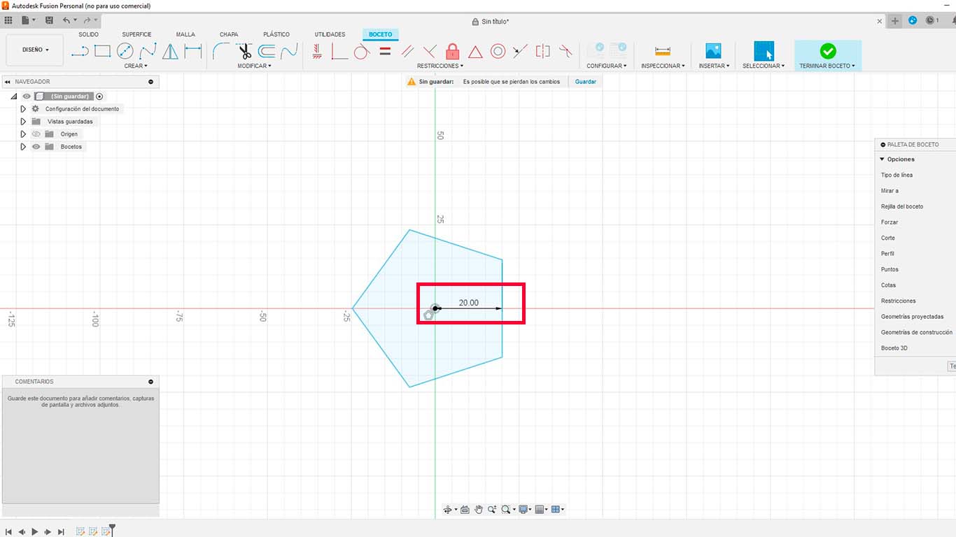
When opening FUSION, we go to the create tab, search for polygon and choose the CIRCULATE POLYGON option.
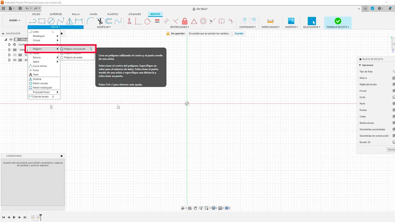
By clicking on the option, a figure pre-established by the program will be created, here we have to change the dimension we want "DIAMETER" and the sides of the polygon, in this case I chose 20 mm and the dodecahedron has 5 sides at its base.
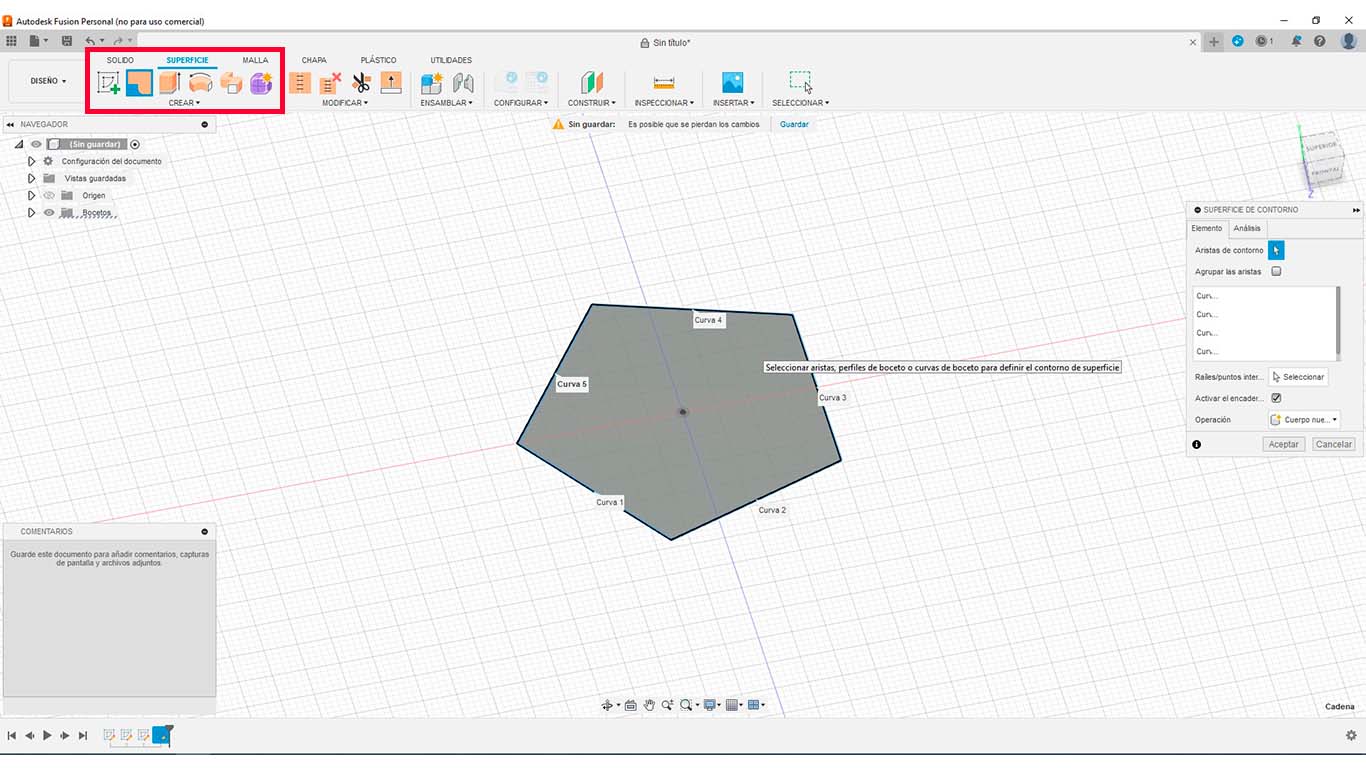
Then we go to the surface tab at the top of the program work area and choose create surface.
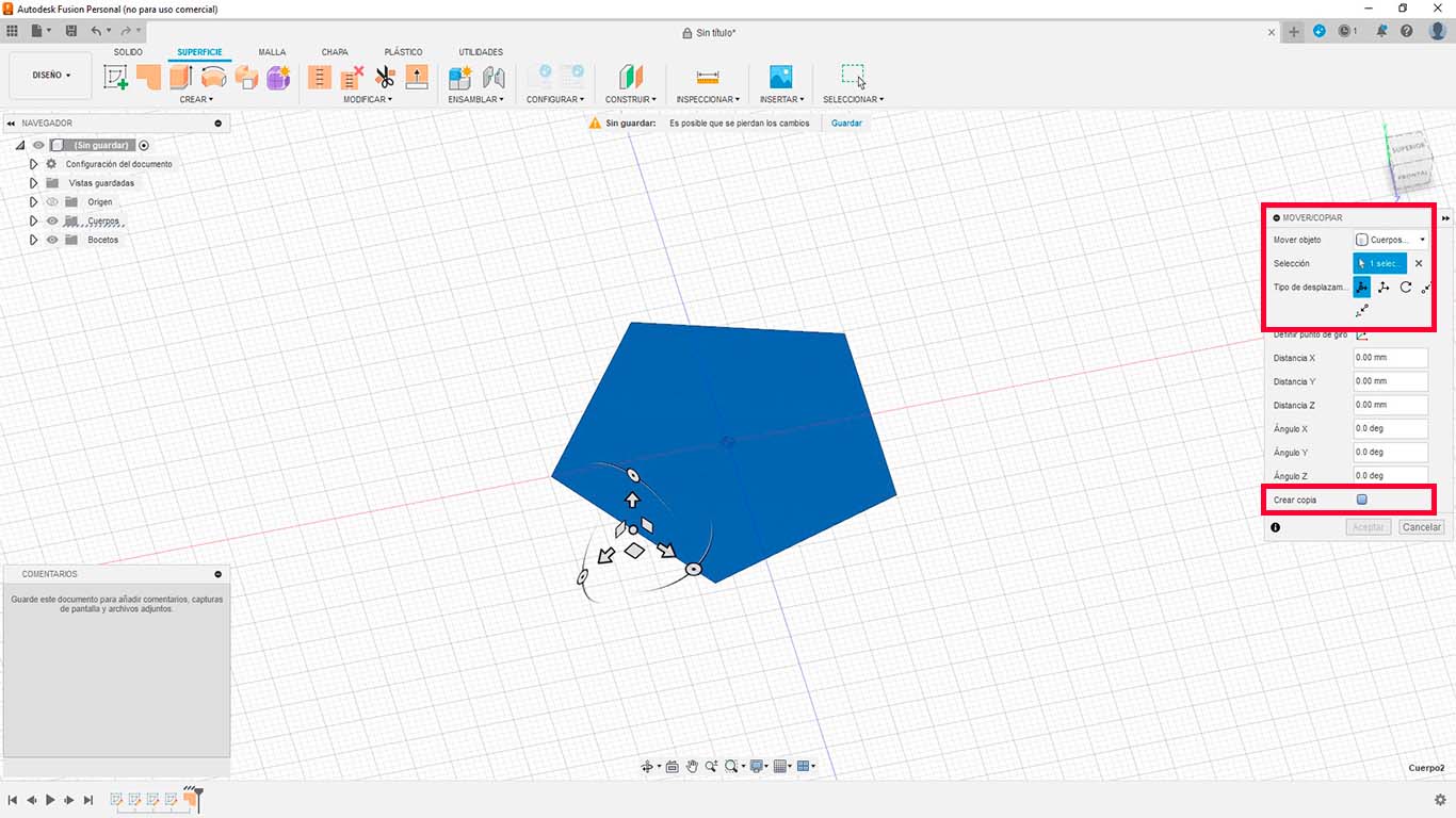
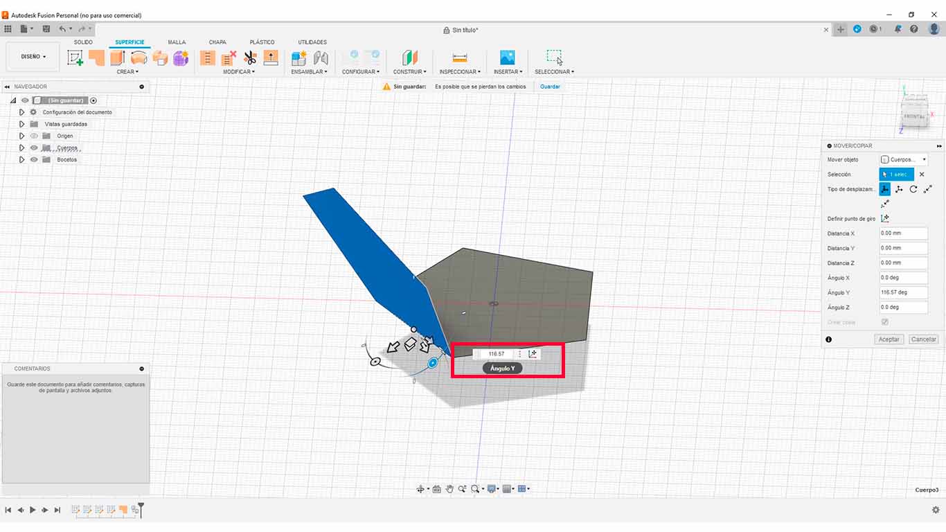
After creating the surface, on the keyboard we press the letter "M" which will activate the MOVE/COPY tab, here we click on the created surface and then at the bottom we click on CREATE COPY. Here we go to one of the edges of the created shape and click in the middle.
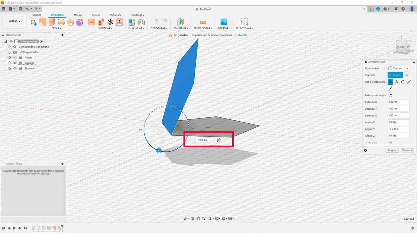
Here a copy will be activated and here we will have to change the angle of the new surface. Let's remember that the angles presented by the faces of the DODECAHEDRON are 116.57° and we have to write that.
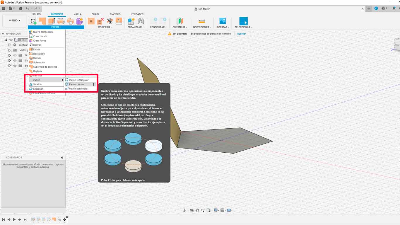
After having the new face with the tilt of the shape. We proceed to search the surface for the CIRCULAR PATTERN option, with this tool we will copy the face to repeat it around the base.
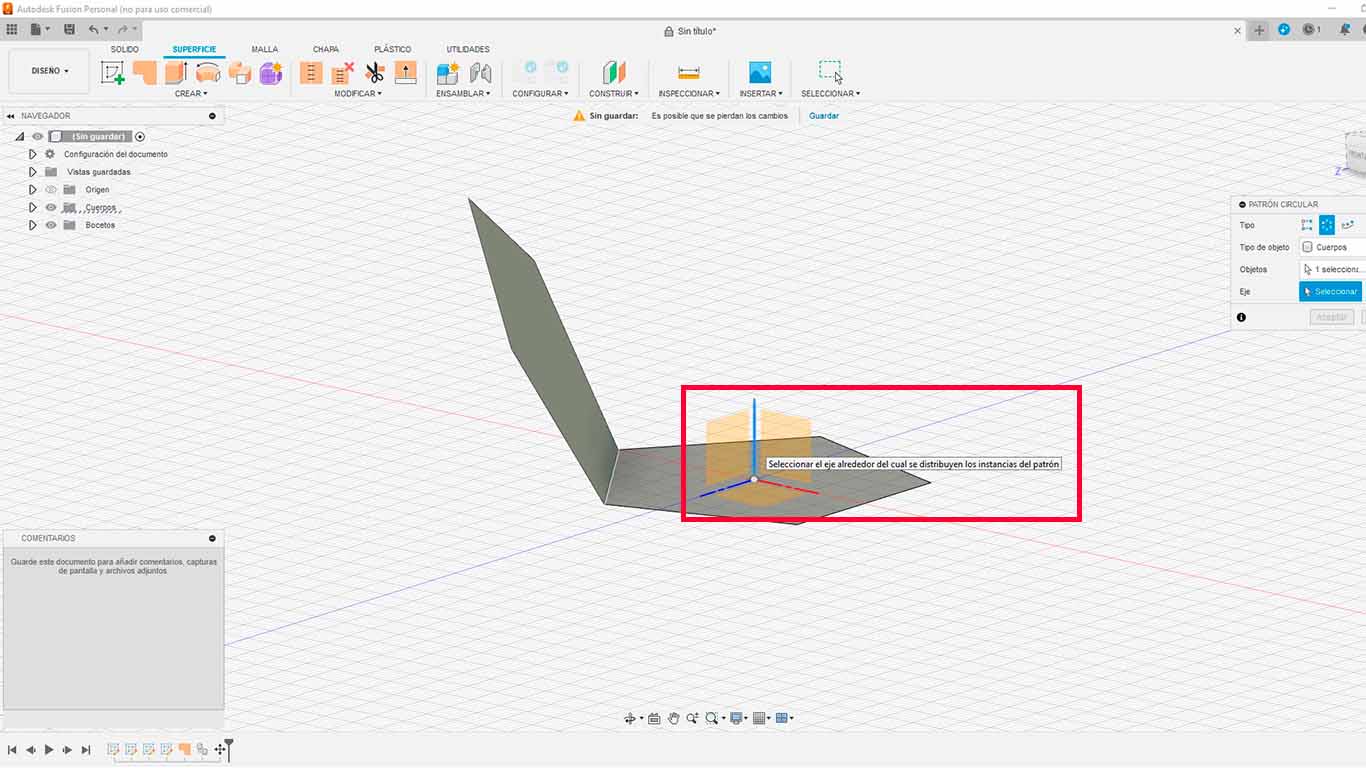
Then we have to choose the axis where the program is going to be referenced to copy, we select the HORIZONTAL axis.
Then a box will be activated where for this occasion we will put "5" because they are the number of copies that we want to generate of the selected face.
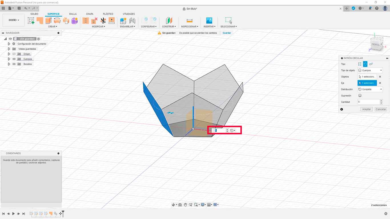
After carrying out the process we will obtain half of the ready dodecahedron.
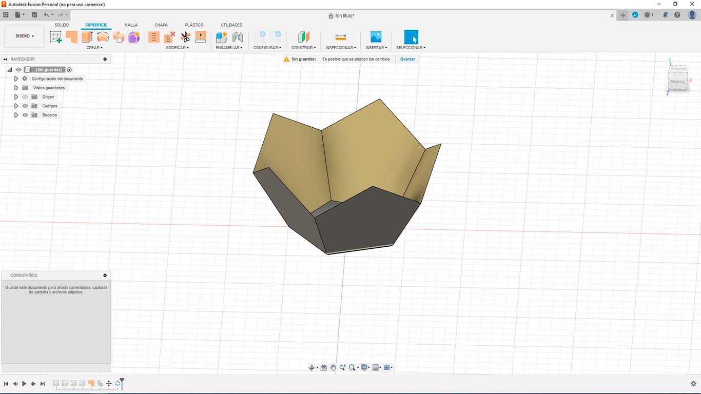
Now we make the other half of the dodecahedron, to do this we have to press the letter M on the keyboard again, we select the entire model made and make a copy upwards.
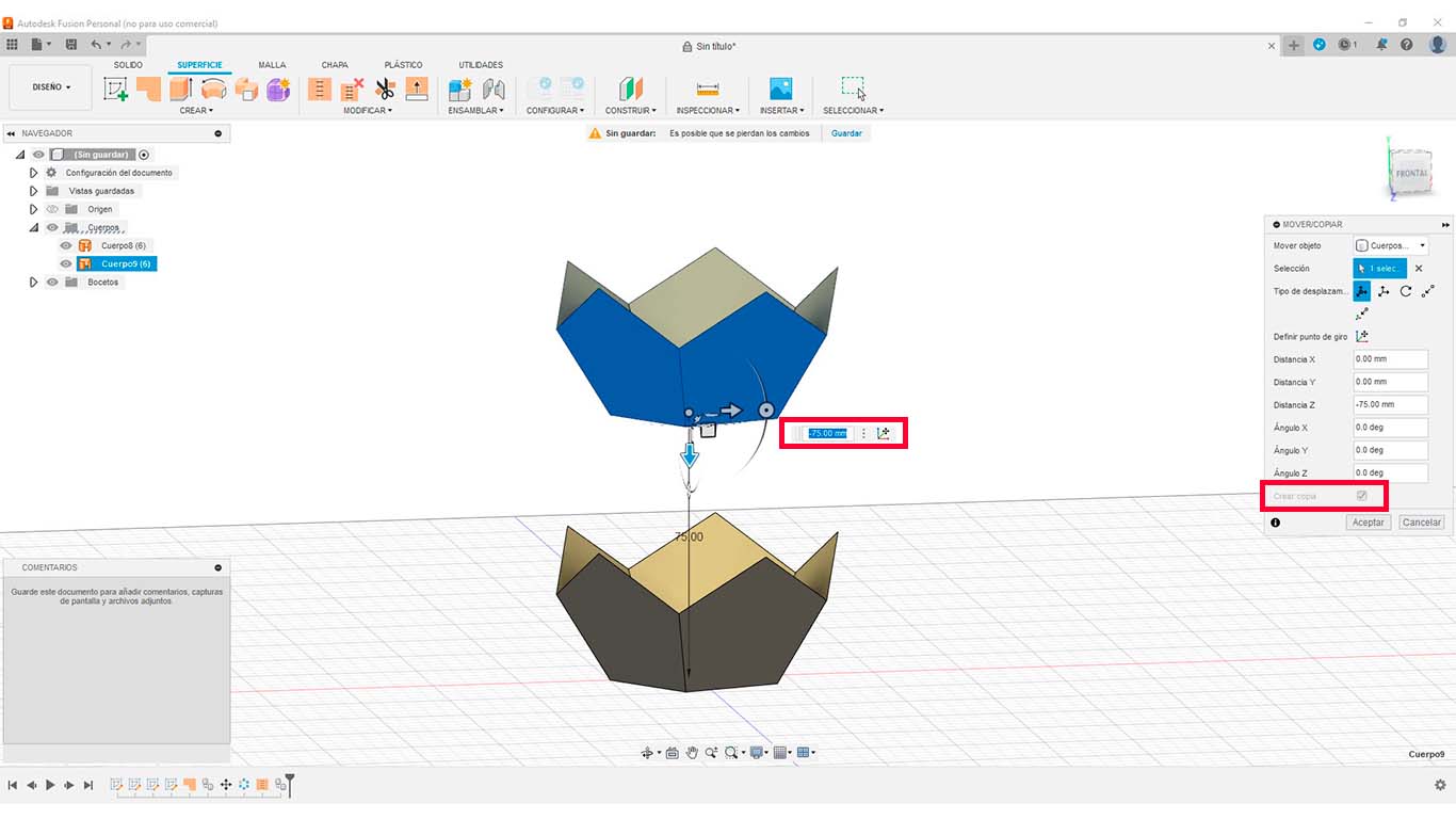
After getting the copy, we rotate the entire new half created.
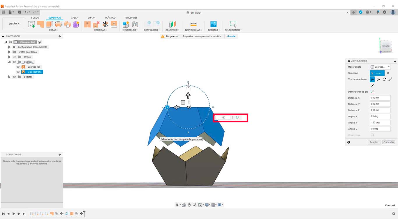
After having the shape rotated, we will proceed to place both figures together. To do this, there is a tool in the MOVE/COPY tab that is a type of movement that we can choose a point and place it at an exact second point. Here is a photo of how I did it
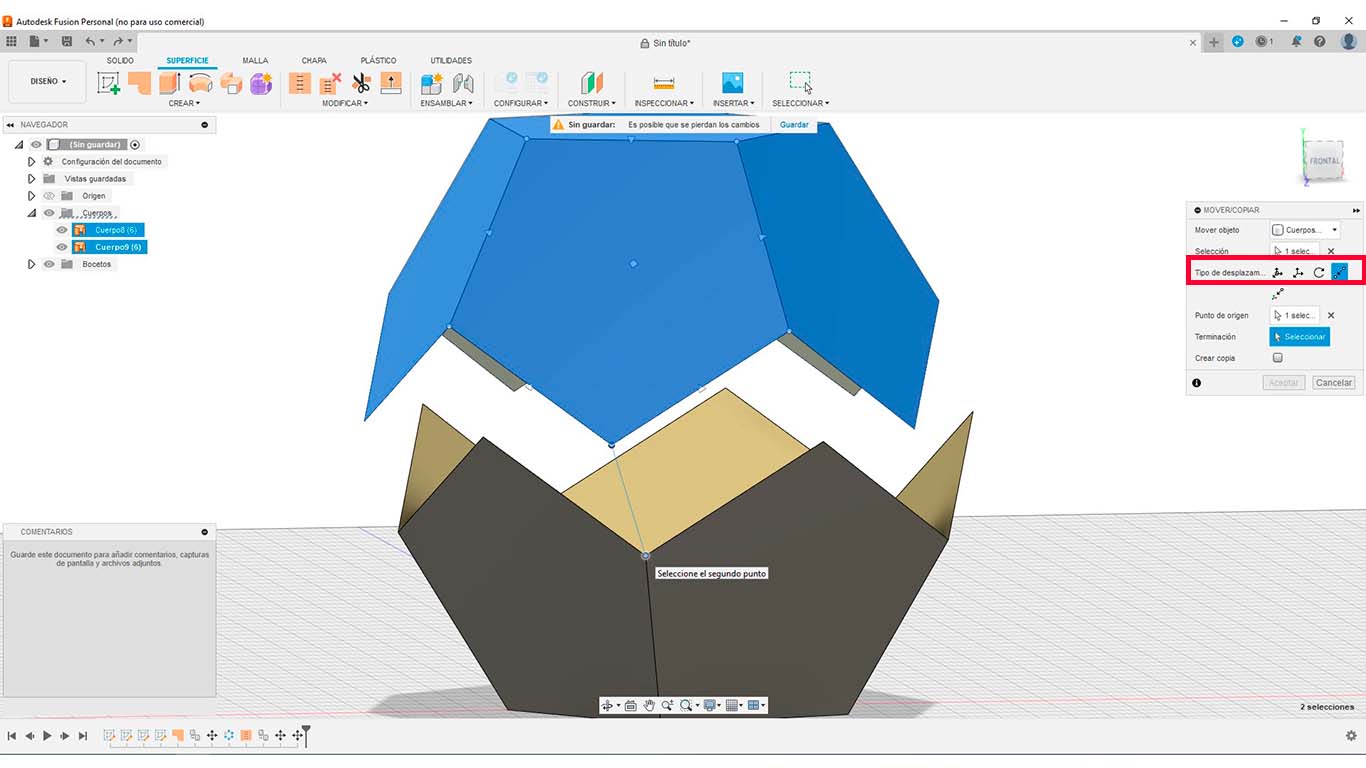
After carrying out the entire process, which is simple, I thought it was going to be complicated when doing it, we can obtain the dodecahedron.
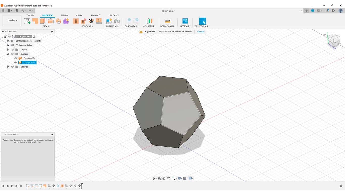
After that, we proceed to cut half of the dodecahedron using a volume or surface and at its base, in my case I generated a cylinder through which I am going to place the liquids for the casting.
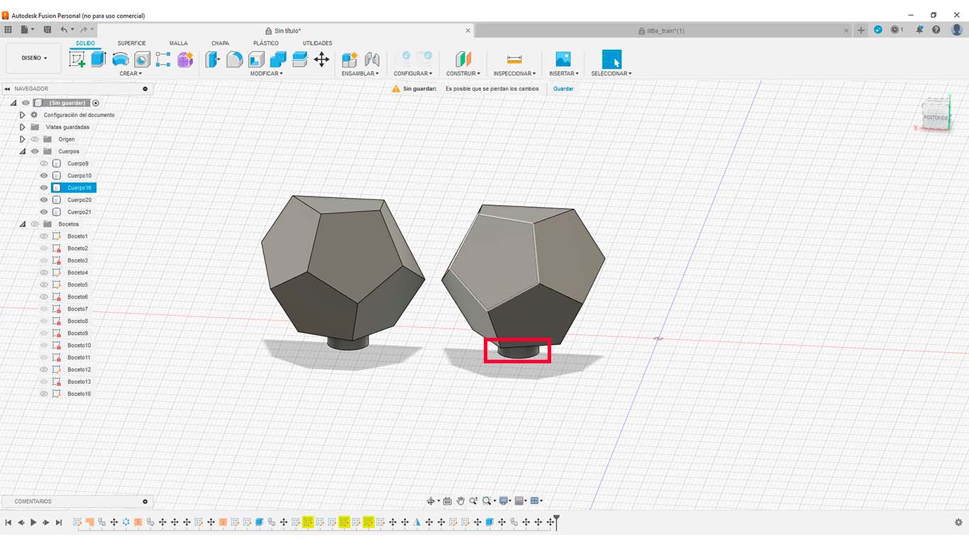
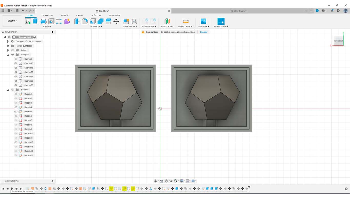
After that, we generate the "DRAWER" which is the volume where my dodecahedron will be contained. This is mainly done to obtain the mold. In my case I have 2 molds to achieve the created shape.
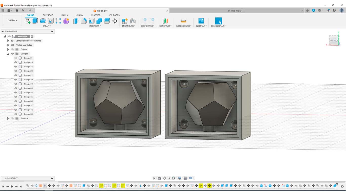
Finally, after having the "DRAWER" we add some "JOINS" so that when making the mold we can have this union and achieve the shape correctly. It is important that it is very well separated and is not smaller than the diameter of the drill that we are going to use.
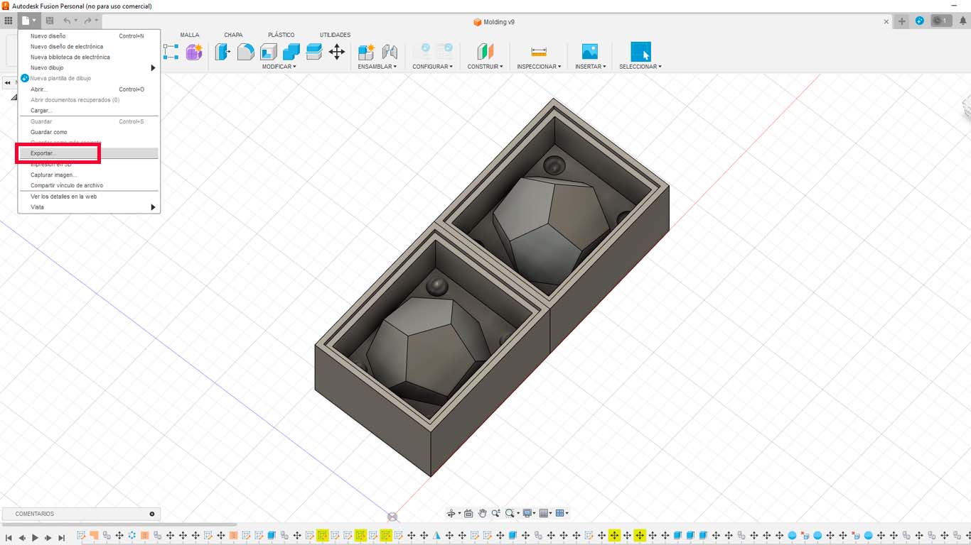
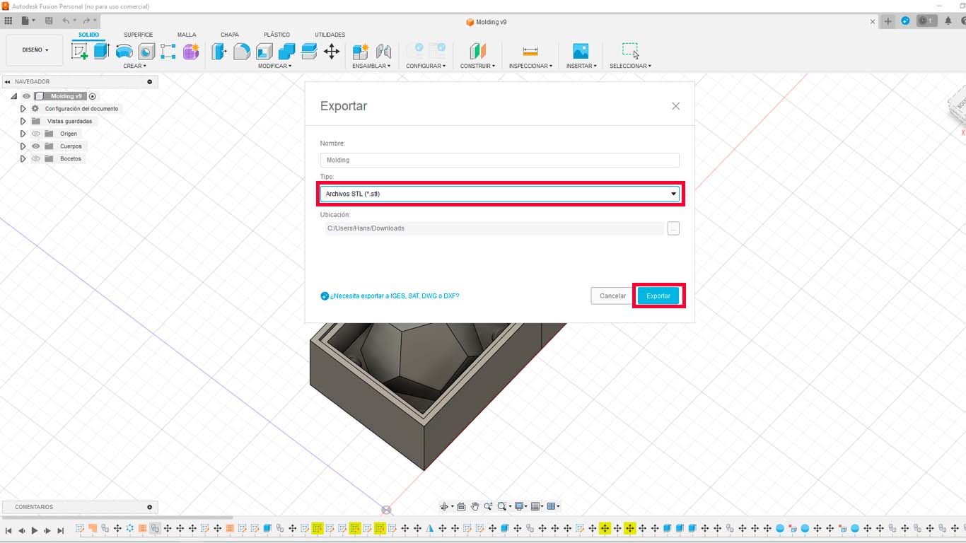
After obtaining the model, we will export it in STL format, this will be useful for both 3D printing and also for milling. In my case, I will use the SHOPBOT to do it in the milling.
3D PRINTING MY MOLD
IMPORT AND PRINTING
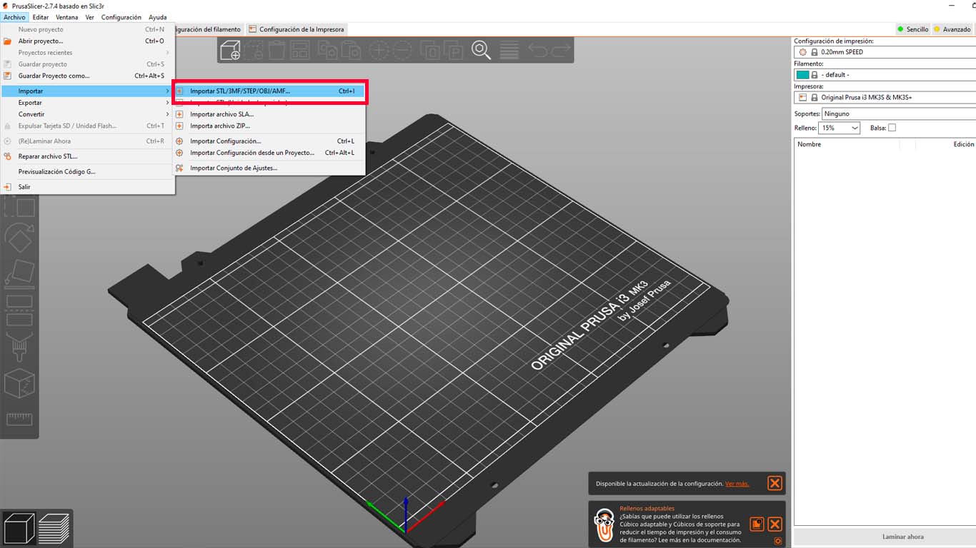
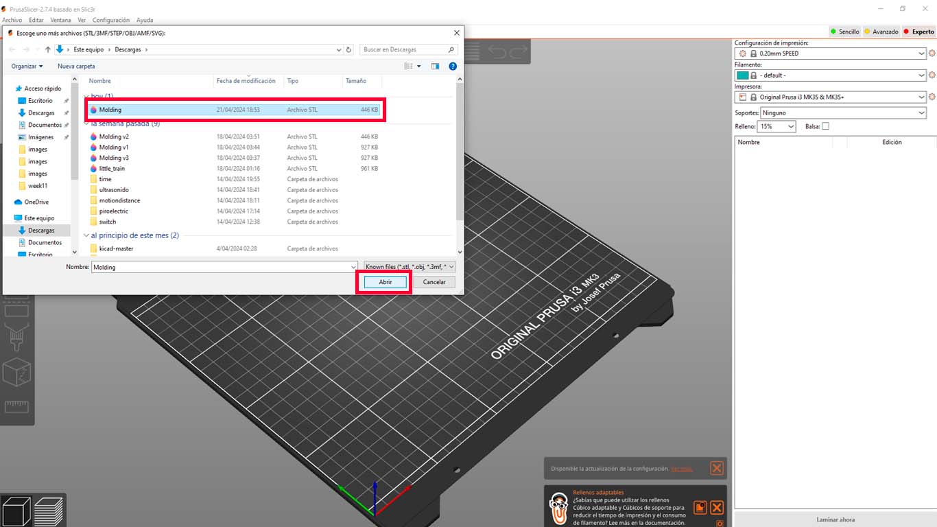
Now I will start with the 3D printing of my mold since I consider that it is easier to do it because I know the process already seen in week 5 of the FAB ACADEMY. First we import the model made in the PRUSA SLICER program.
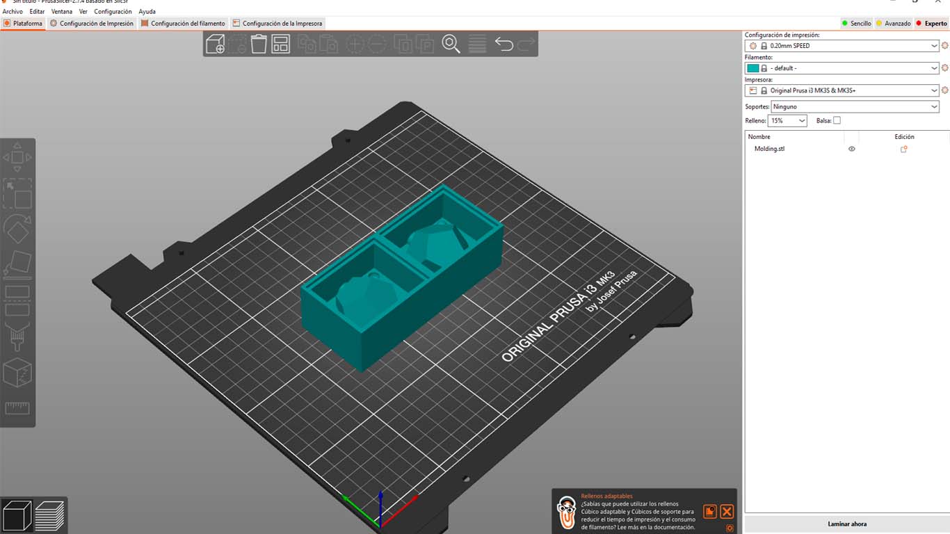
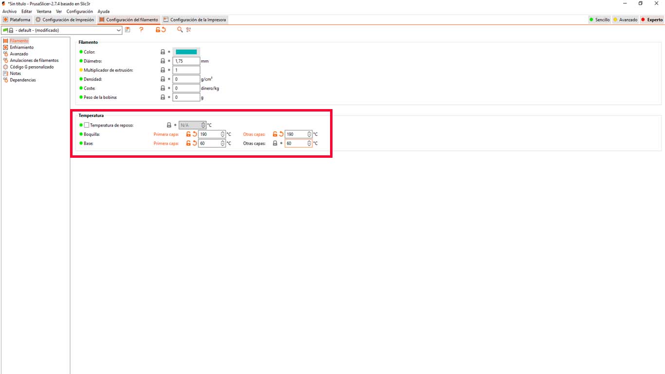
After checking if the imported object is correct, it does not present any problem. We will proceed to configure the temperature of the nozzle and the base. In my case, I will use white PLA and according to the supplier I need 190° at the nozzle and 60° at the base.
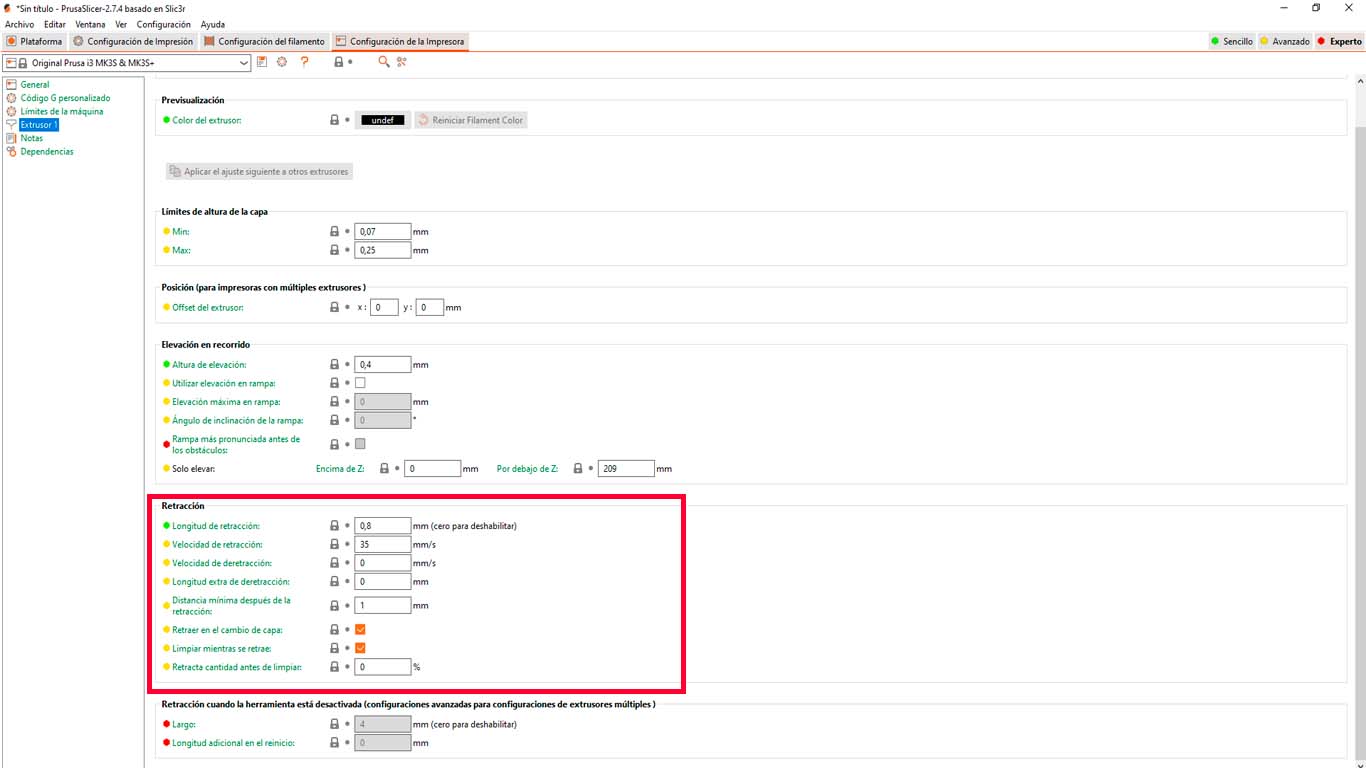
Likewise, I will configure the printer retraction since I have seen that it is important and I have had some observations. Performing the tests in week 5 helps me a lot to obtain very clean figures that do not have so much spider web. Here I leave the configuration for my 3D printer.
Finally, after reviewing the temperature and shrinkage details, we moved on to laminating the figure and then I moved on to 3D printing.
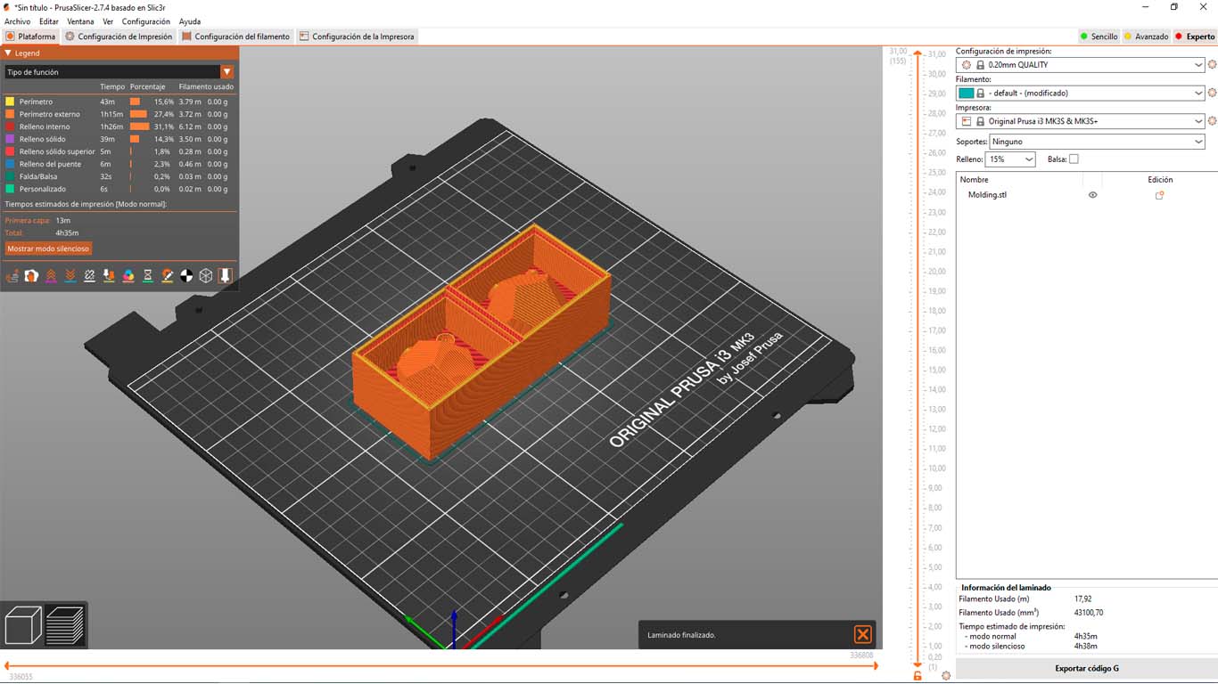
Here I leave a series of photographs of the 3D printing process of my mold, it is always good to check if everything is fine and the printer is making the model.
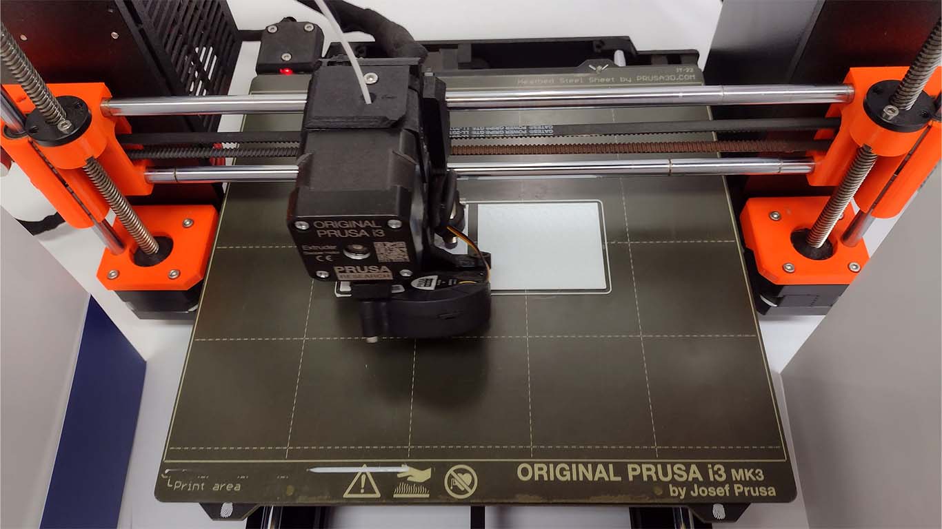
This photograph is when I was already 1 hour into printing my mold.
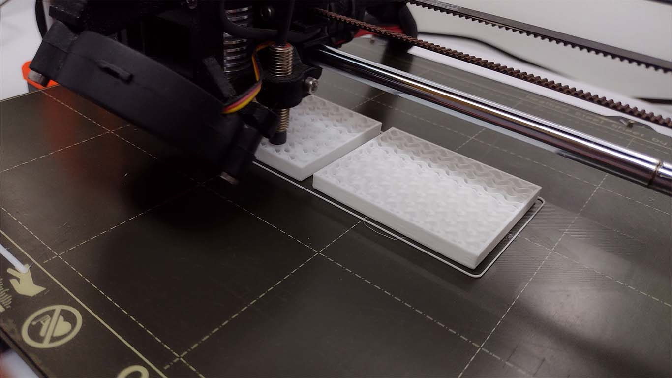
Here the 3D printing had approximately 2 hours of work and everything was fine.
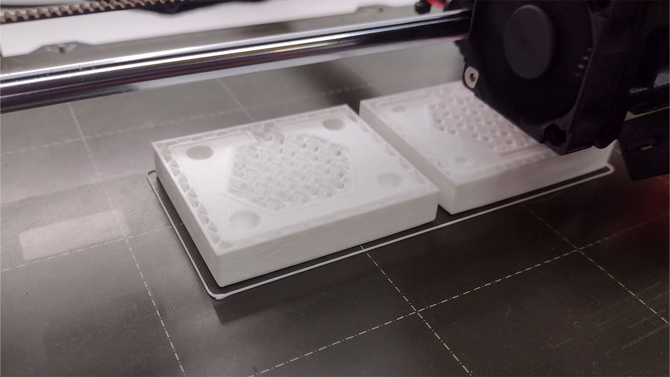
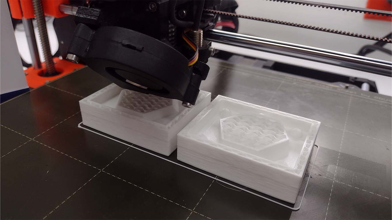
In this photograph, when printing I already had a time of 3 and a half hours, I was checking that my DODECAHEDRON model could turn out well, because maybe I would have to change it, but it didn't.
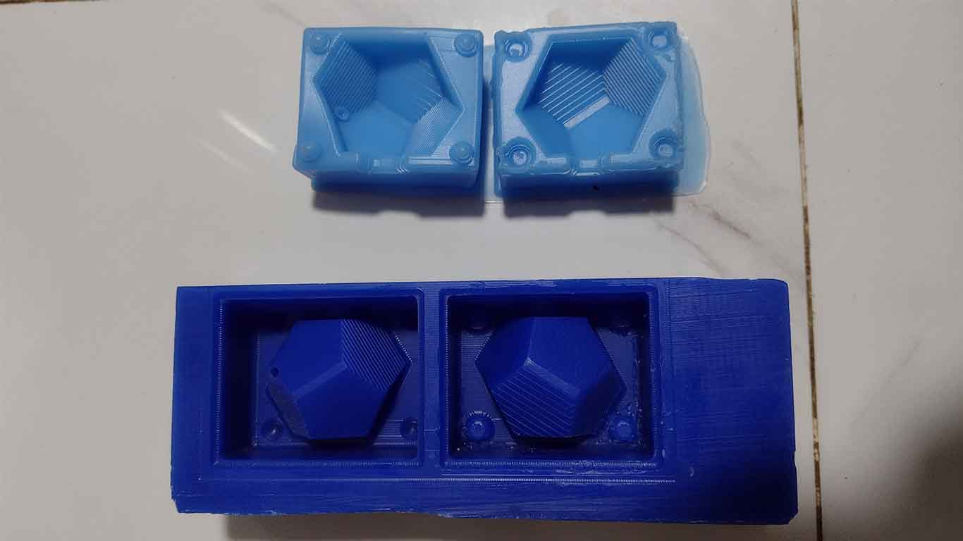
Finally, after approximately 5 and a half hours, I was able to obtain my 3D printed mold, I could see that everything was in detail and as I wanted. Here I leave a photograph of my printed model.
MILLING MY MOLD
INVENTORY FOR ASSIGMENT
To mill my wax mold, I had to make an inventory of all the things I would need to make it. Here I show the components I used to achieve the milling.
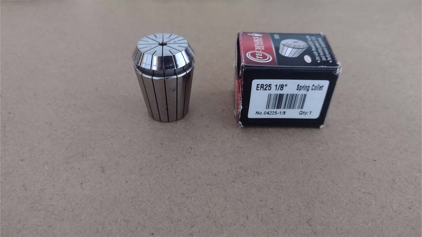
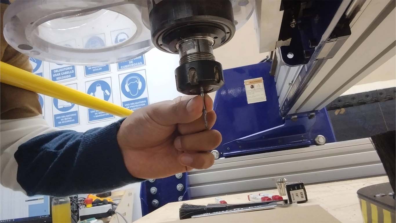
First, I found the 1/8" SPRING COLLET for the SHOPBOT that was necessary for the assigment since I thought that at FAB LAB UCSUR we did not have it and we had to do it on the ROLAND SRM20, but fortunately our SHOPBOT had it.
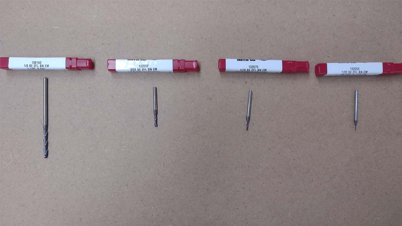
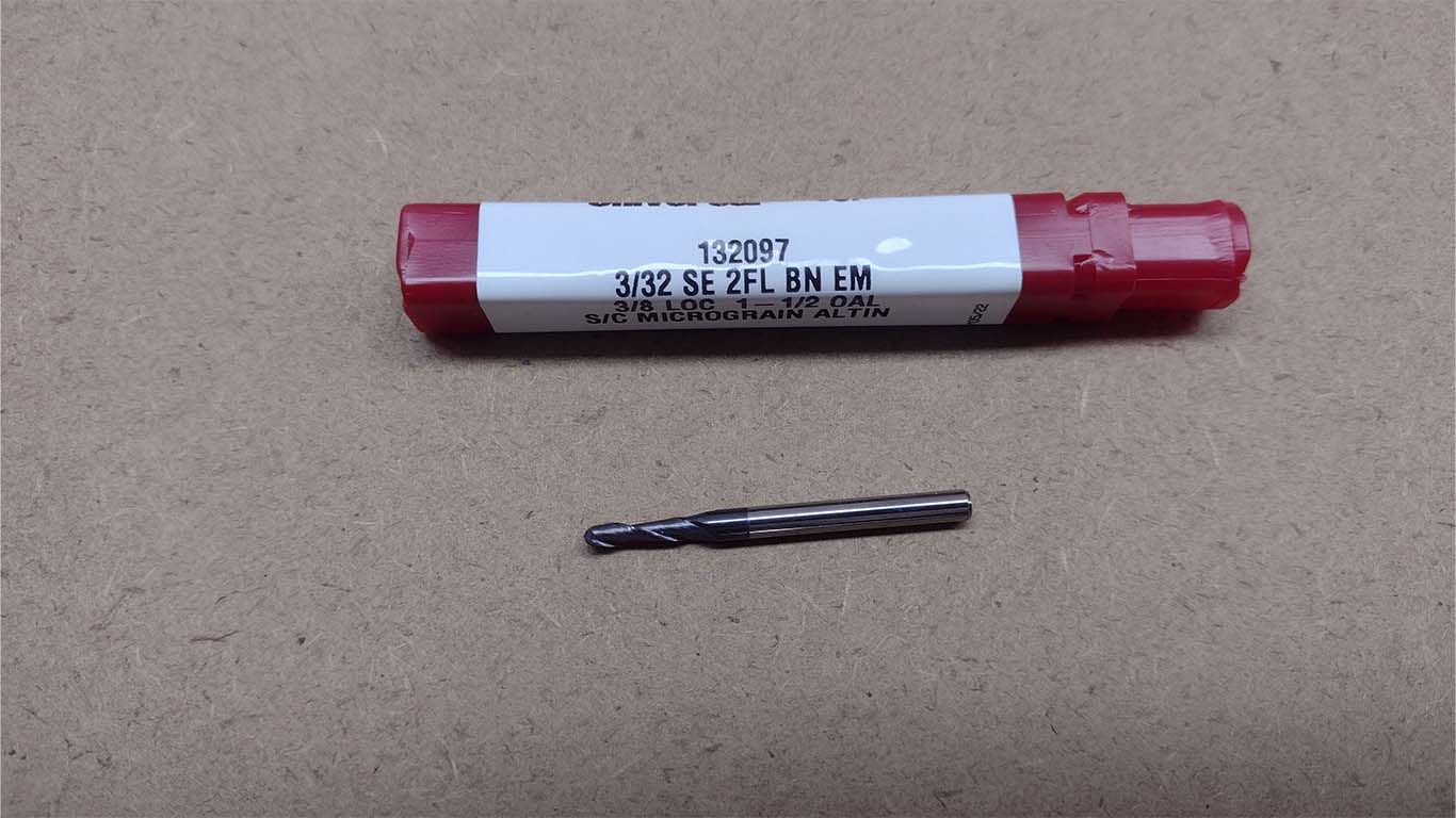
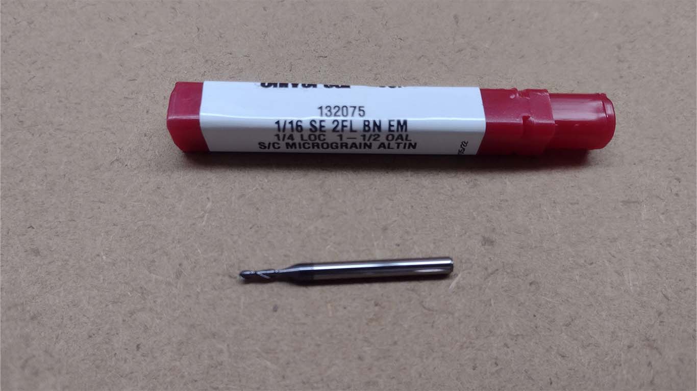
Then, I reviewed all the cutters we have to develop the assigment, where I could see that we have 1/8", 3/32", 1/16" and 1/32" cutters that I thought were all going to be used for the assigment. Here is a screenshot of all the drills.
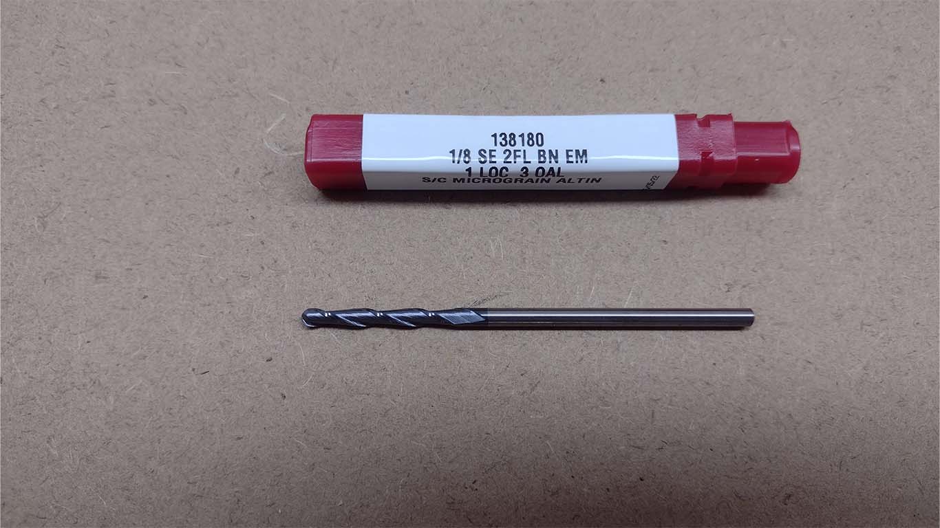
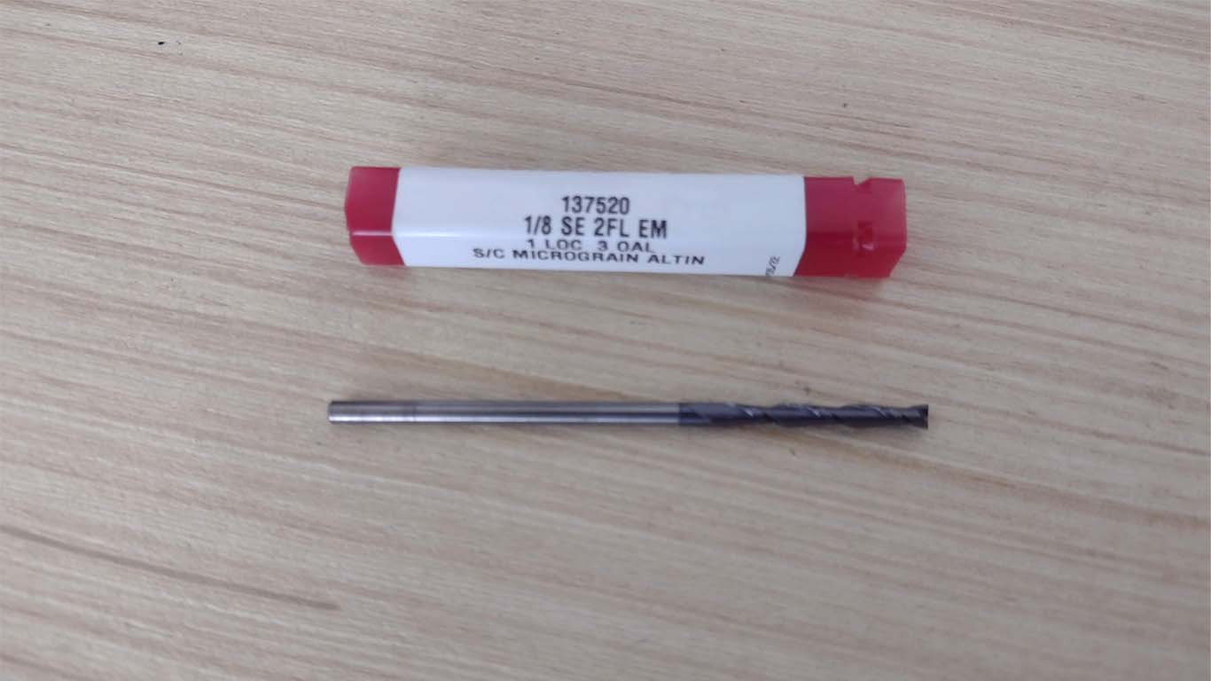
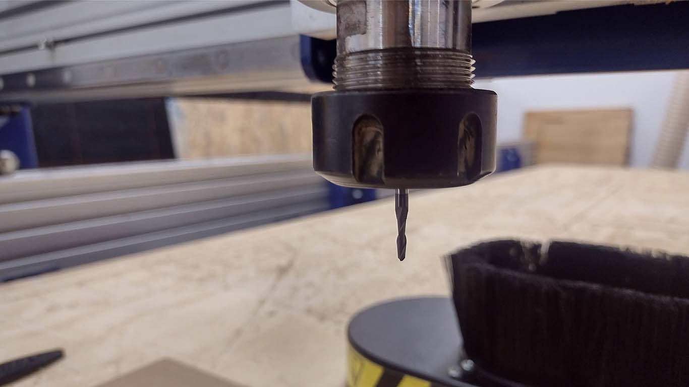
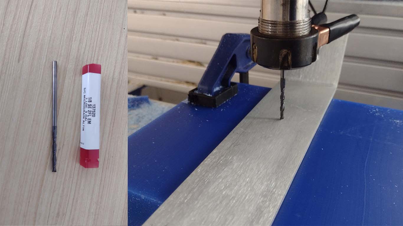
Finally, I also looked for the type of milling cutter we wanted for finishing and cutting. I was able to find a 1/8" cutter, here's a photo of what I used.
CONFIGURATION TO MILLING ROUG WITH MODS CE
To begin milling my mold, first we have to do the rough thing of making a first layer of excavation of our model and then proceed to finishing. To do this, we will use the 1/8" cutter shown in the previous section and here I will begin to show how the MODS.CE configuration is.
First, we start by choosing the machine with which we are going to carry out the assignment, in my case I wanted to use the SHOPBOT and that is why I choose it in the MODS CE and for the ROUGH part, we have to choose the MILL 2.5D STL according to the image.
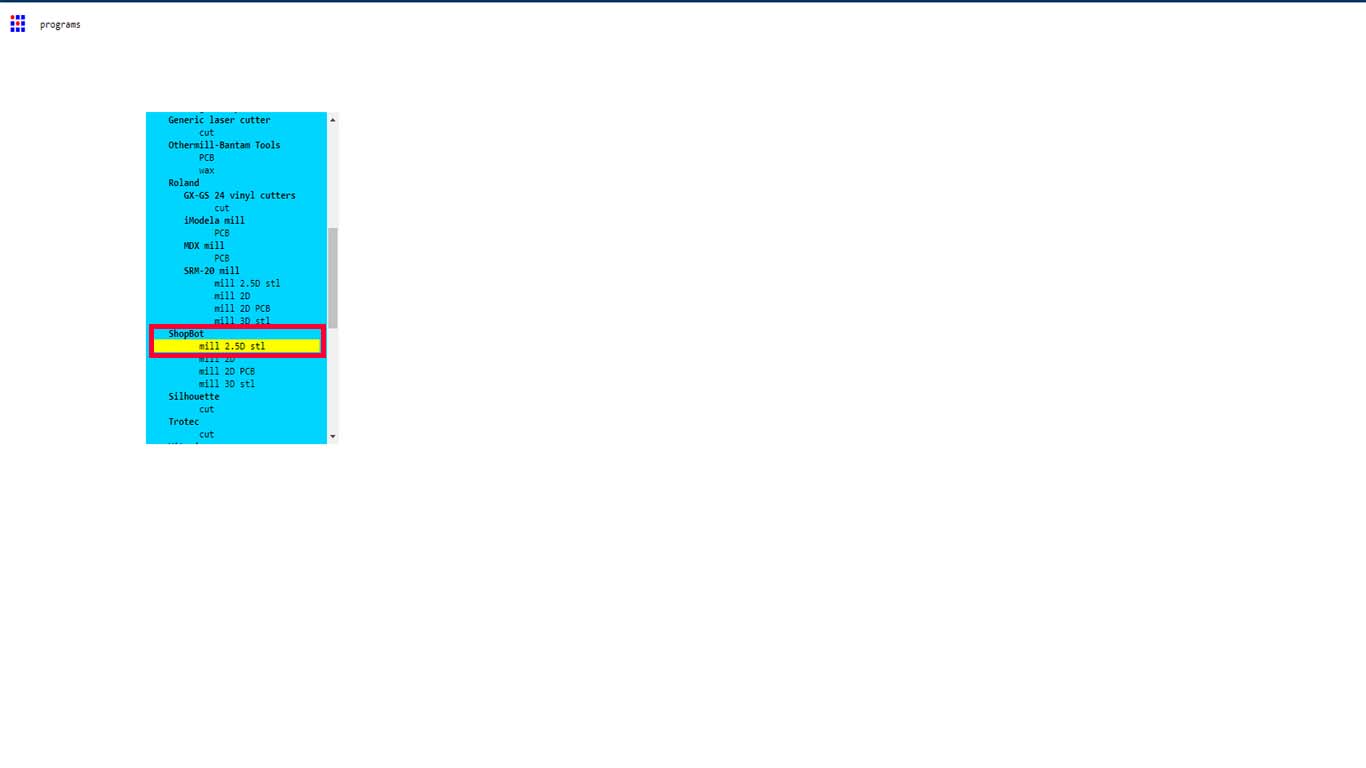
We check that we correctly chose the option mentioned at the top of the MODS CE window.
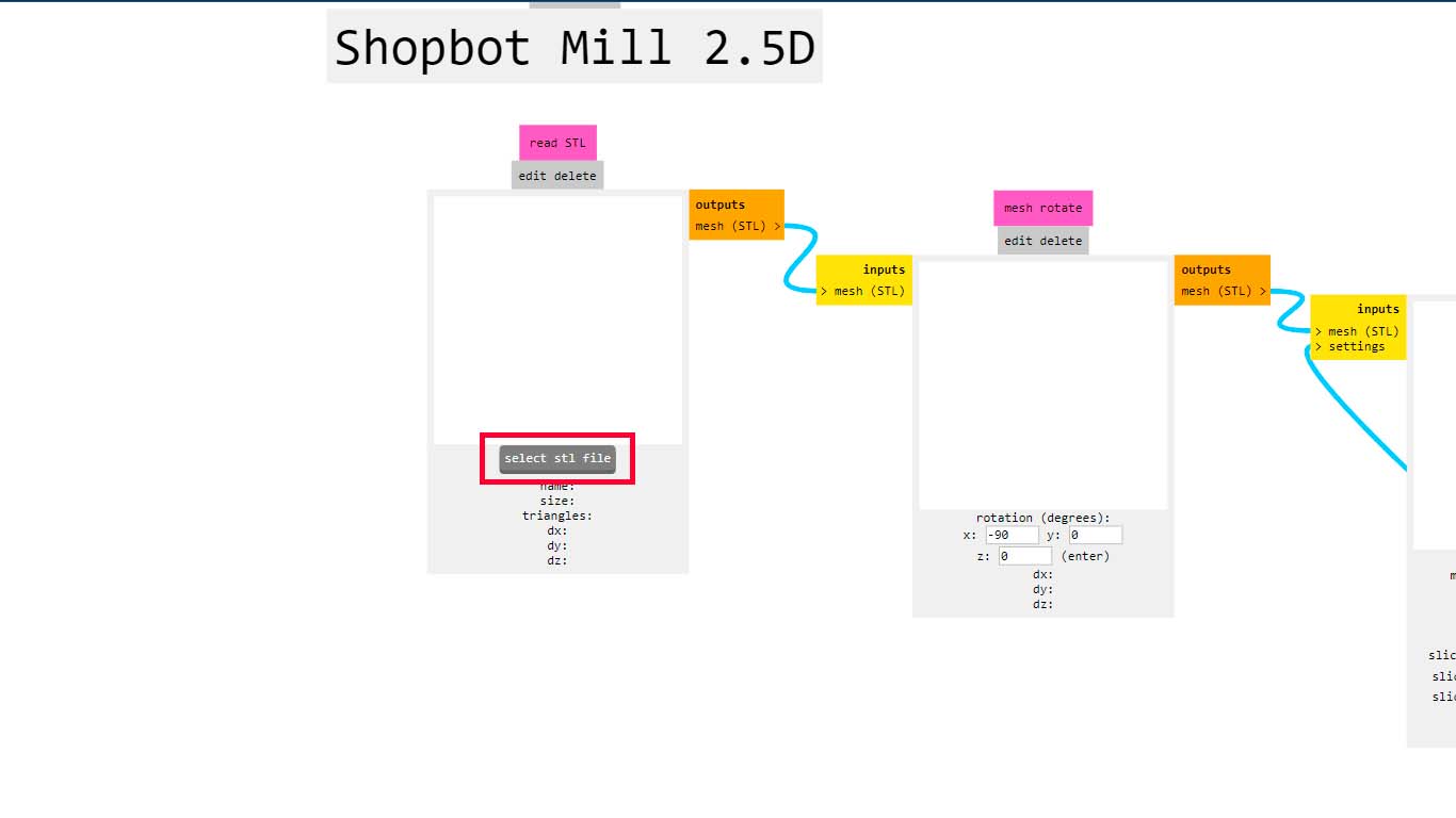
Next, we load or import our STL FILE of our model. We click on SELECT STL FILE and a window will appear where we have to search for our model and we open it.
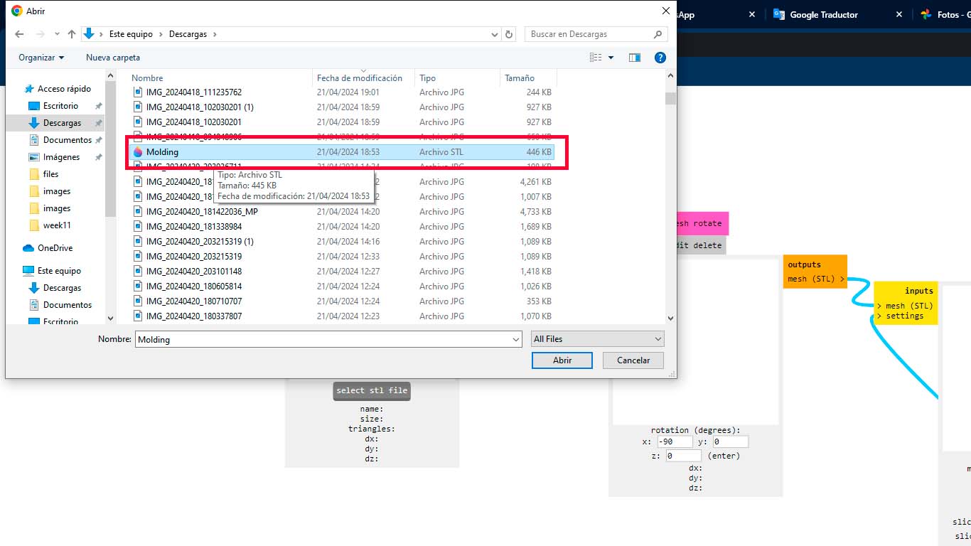
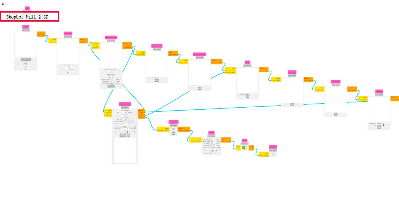
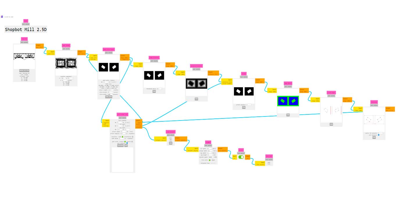
We will load all the parts that make up the MODS CE and we will configure the important points to take into account for milling the wax.
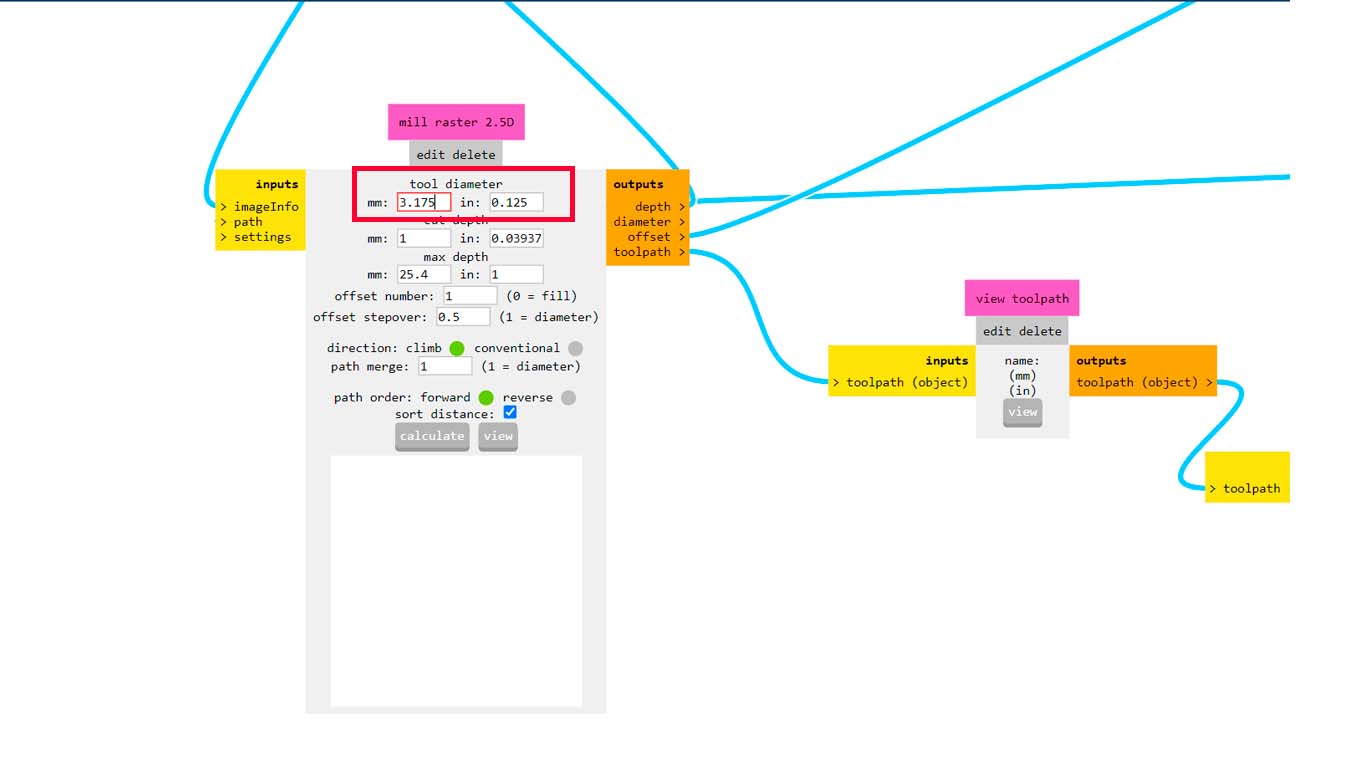
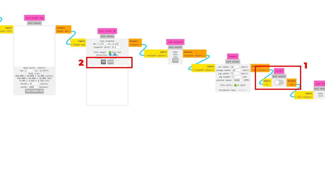
First, in the MILL RASTER 2.5D window, we will change the TOLL DIAMETER for the measurement we have on the milling cutter, in my chaos I chose a 1/8" milling cutter to do the ROUGH work, so I change it to 3.175 which is the measurement in mm .
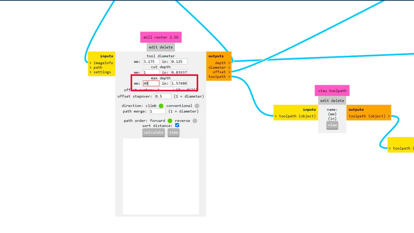
Then we will change the MAX DEPTH configuration, which is the maximum height that MODS CE will remove the layers for cutting. In my case I increased to 40 mm, but the ideal would be to have the models less than 30 mm.
After making the changes mentioned above, we turn off the "DOWNLOAD" button that is marked with the number 1 in the image and click on "CALCULATE" to have a preview of the cut.
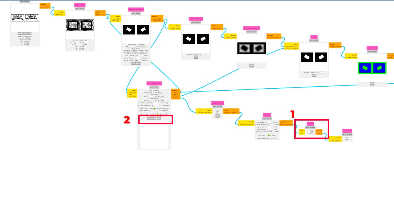
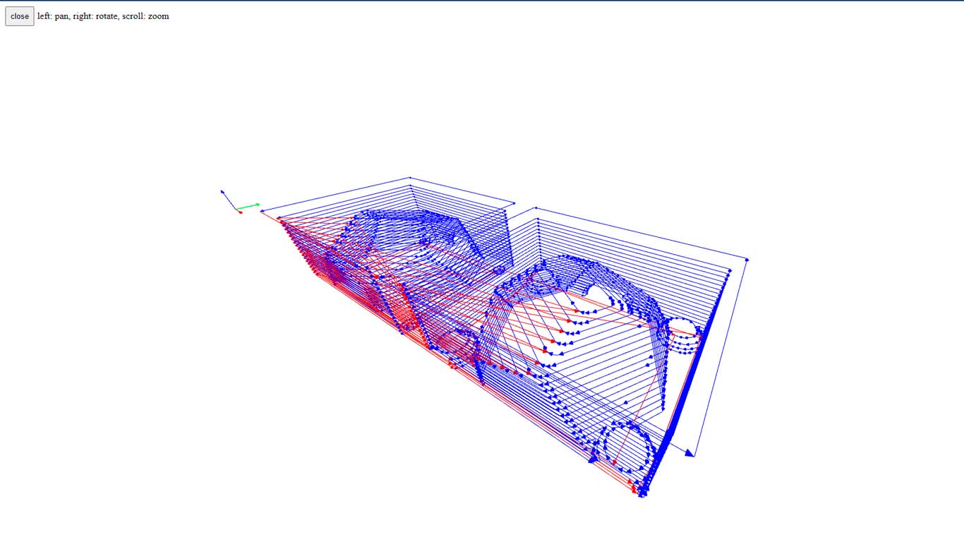
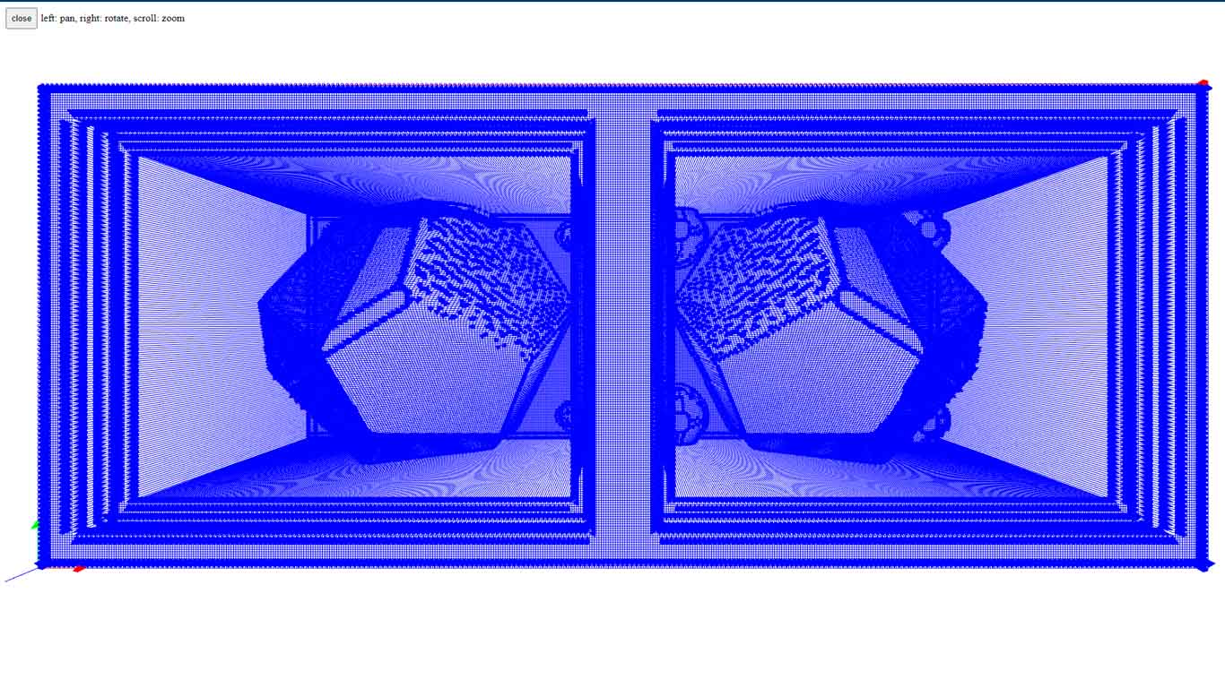
Here I show the preview of my model of my MOLD, here we can see the trajectories that the milling cutter will have in order to achieve my model. Here you have to check if everything is ok or if some things are missing. If everything is fine, let's move on to the next configuration.
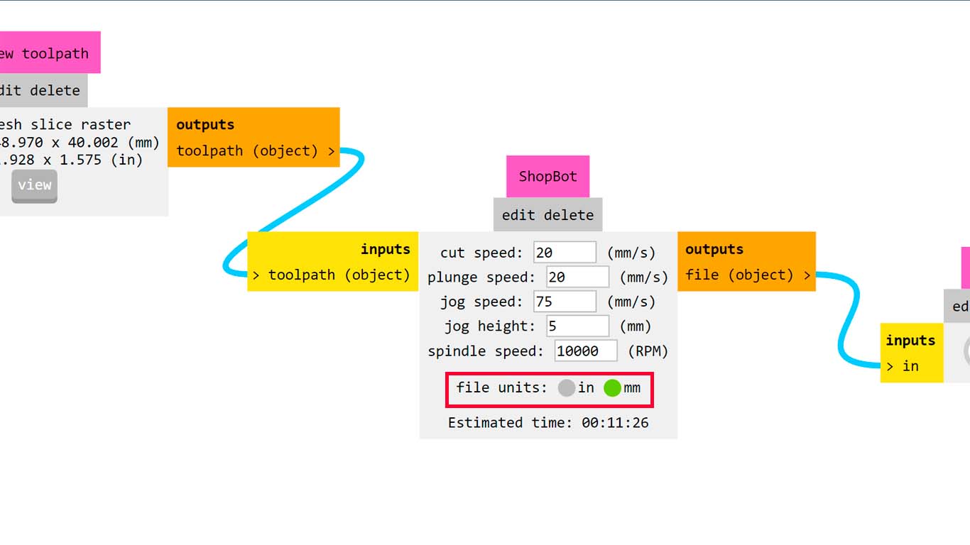
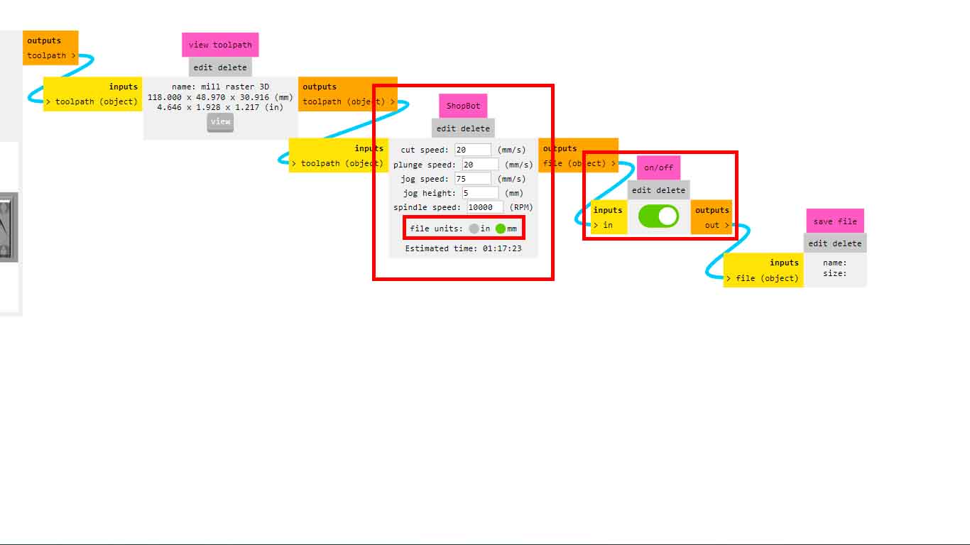
Finally, in the SHOPBOT tab, in my case, I had to change the FILE UNITS since on the first occasion I had problems because my SHOPBOT is configured by MM and not by IN, keep this observation and configuration in mind for your machine since It is important and you will think that your machine does not perform the trajectory, in reality it is because it does not have the appropriate units.
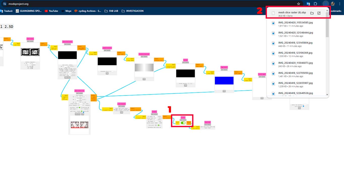
Finally, we can activate the DOWNLOAD button again and the file will be downloaded so we can send it to the SHOPBOT.
MILLING ROUG MY MOLD - TEST 1
To begin routing the wax for the mold, first change the SPRING COLLET on the SHOPBOT for the 1/8" burs and attach the cutting bur to do the "RUDE" work that needs to be done first.
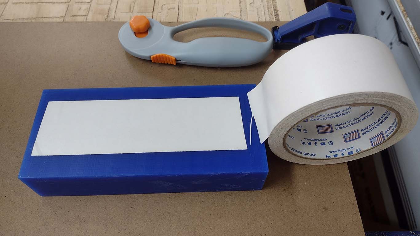
Also, I placed double contact tape on the wax to be able to hold it on the shopbot.
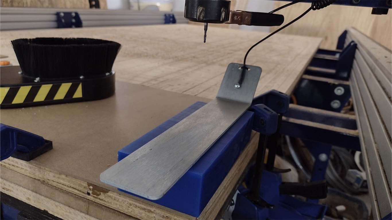
After carrying out the following steps, I began to calibrate the Z axis of the machine and also checked that the cutter is very well held in the sping collet for correct work.
After having the wax milled, I had some problems. First, the wax moved when doing the milling since the force that the machine has is very strong and the double contact tape did not resist that force.
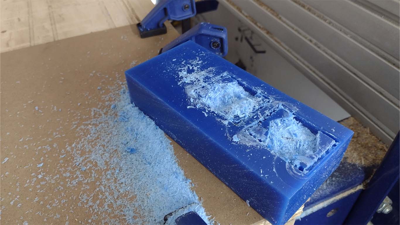
Then, when cleaning the wax I could see that the machine was doing a good job but the part of the machine was colliding with the wax and that the bur did not reach the height that my model had. Here is a photo of how the wax looked due to the shock it had.
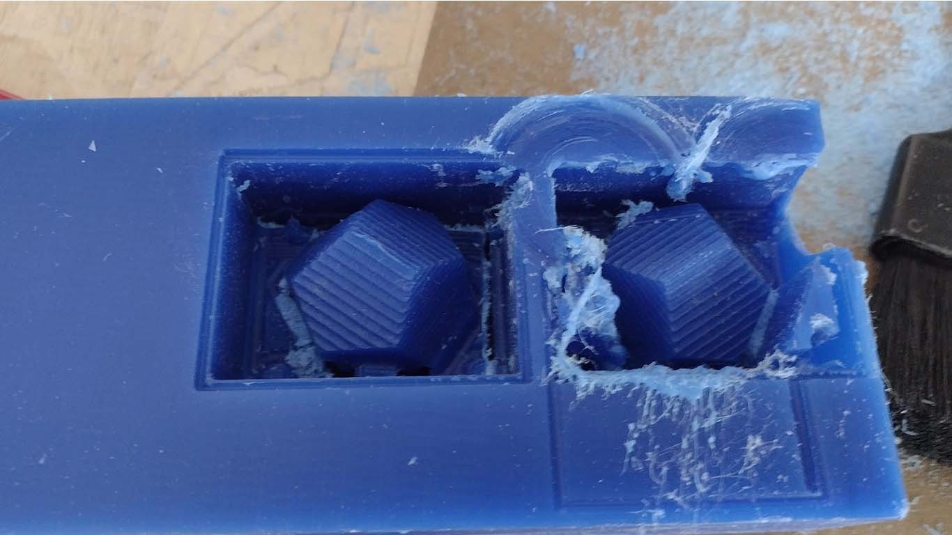
Then, I started to check the wax and I had the problem of "COLLECTION" that Adrian Torres in the OPEN GLOBAL TIME explained to me that it was because my model was square with straight sides and that the corners suffered the impact first because the height of the drill bit is less than the depth of my model. I must be careful and review these details when using the machine.
SUPPORT OF GLOBAL OPEN TIME
GLOBAL OPEN TIME SUPPORT
On Saturday I joined the OPEN GLOBAL TIME and as always Adrian, Rico and Pablo give us some recommendations and explain to us the mistakes we may be making and how we could solve them. They helped me a lot to better understand the work of this assignment. I lost the photographs I had captured from the meeting but they managed to explain to me the mistake I was making and also how to correctly perform the ROUGH and FINISH milling. Thank you teachers for another week of teaching and sharing your knowledge.

MILLING ROUG MY MOLD - TEST 2
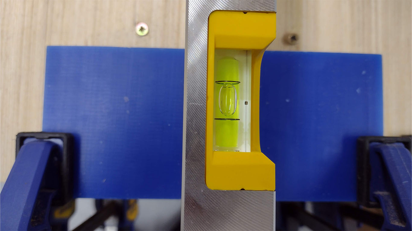
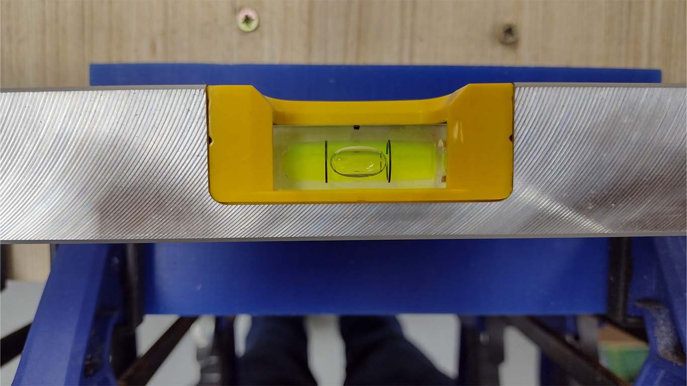
Before starting to carry out my second milling test, I checked the level of the bed of my shopbot because I remembered that for the 1st test, I saw that the machine on one of the sides did not cut the wax. So it is good to check the level of the material.
For the second test and taking all the recommendations they gave me in the GLOBAL OPEN TIME, I changed the milling cutter to do the ROUGH milling of my mold. First I changed the router bit to a 1/8" cutter with a straight tip which was a recommendation and started calibrating on the machine.
Then, I checked my settings again in the MODS CE and had the wax milled done, here is a screenshot of the process. I also added some hooks that we have to grab the wax. Always checking that there is no collision with the machine.
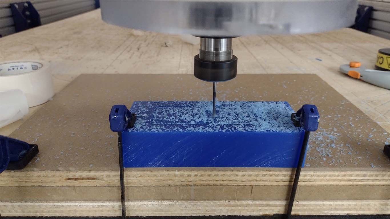
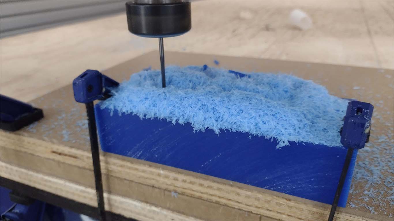
Finally, after approximately 12 minutes, I was able to review the result I have and the teachers' recommendations really helped me a lot. I could see that the RUDO milling did its job correctly. Now we will move on to finishing.
CONFIGURATION TO FINISH MILLING WITH MODS CE
Similar to the steps carried out for the RUDO milling that we did on the first occasion, only that when entering the mods and choosing what type of milling we are going to do, we now have to choose the MILL 3D STL, this is used for the milling of finish to achieve this assigment. Below is a guide on how I achieved the finish of my mold.
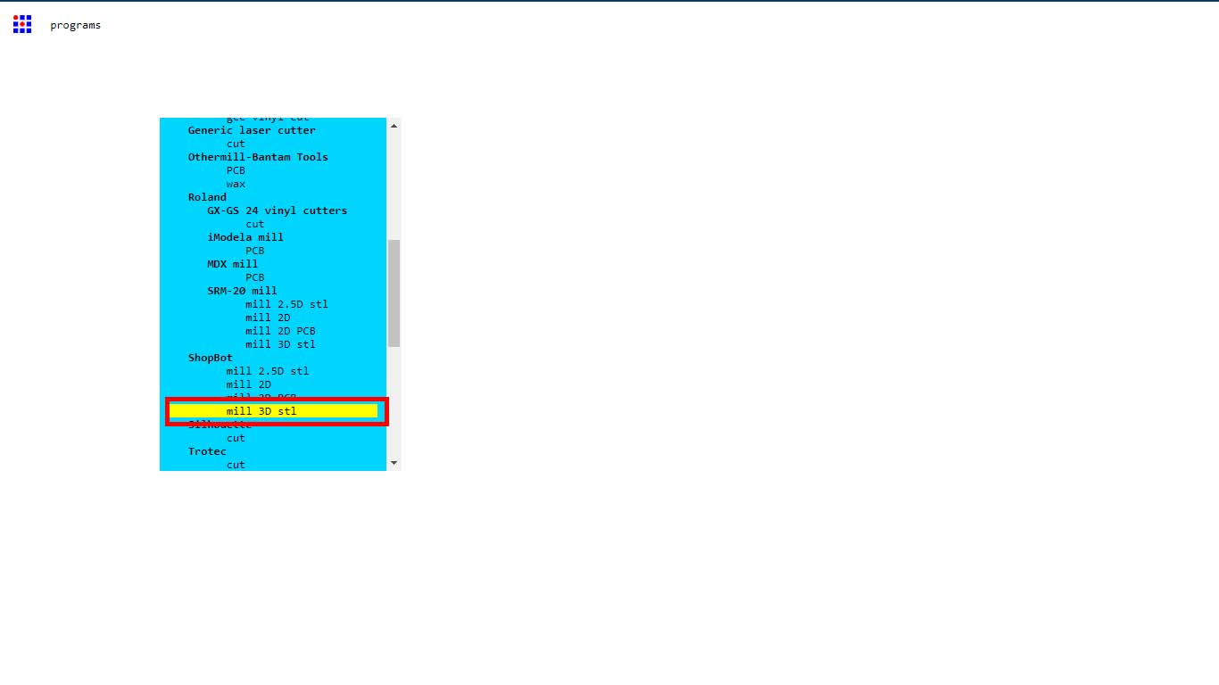
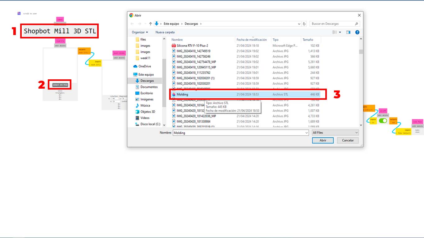
Then, first we check that we chose the MILL 3D STL option correctly and that it is in accordance with the machine we are going to work on. Secondly, we click on SELECT STL FILE and finally, we choose our file from our mold and open it.
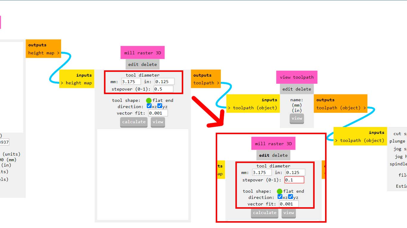
Here we will only change the configuration in the MILL RASTER 3D window where I will try to explain how it works. First, we have to set the diameter of the milling cutter that we will use. In my case I will continue using the 1/8" cutter but with a round tip that is used for finishing, which is why we have in the TOOL DIAMETER section the value of 3.175, which is the measurement in mm of the 1/8" cutter. Now, at the STEPOVER point, we have to consider the following, that the lower the value, the more detailed we will have our mold. In my case, I used the value of 0.1 and finally, the DIRECTION section is important since we can only do it on one axis, but in my case select both to have a better finish.
Then, we turn off the download button to have a preview and it does not download and then we click on CALCULATE. Where it will take a while to load due to the detail we want to have.
Here is a screenshot of my model with the entire trajectory that my model was going to have to achieve the detail at 0.1 with the 1/8" milling cutter. You must be patient when the preview page loads because due to so many lines it takes a while don't worry.
Finally, in the SHOPBOT window we review some data and remember that in FILE UNITS, in my case I have to choose MM since by default it comes in IN values, which my SHOPBOT machine reads, but does not make any movement, that is why it is This point is important and that it goes according to the unit configuration that your machine has and then we activate the download button for our trajectories.
FINISH MILLING MY MOLD
After obtaining the FINISH MILLING file, we begin to configure the SHOPBOT to perform the milling. First I placed the 1/8" round nose cutter, where I configured the Z axis and what we should do whenever we change cutters on the machine.
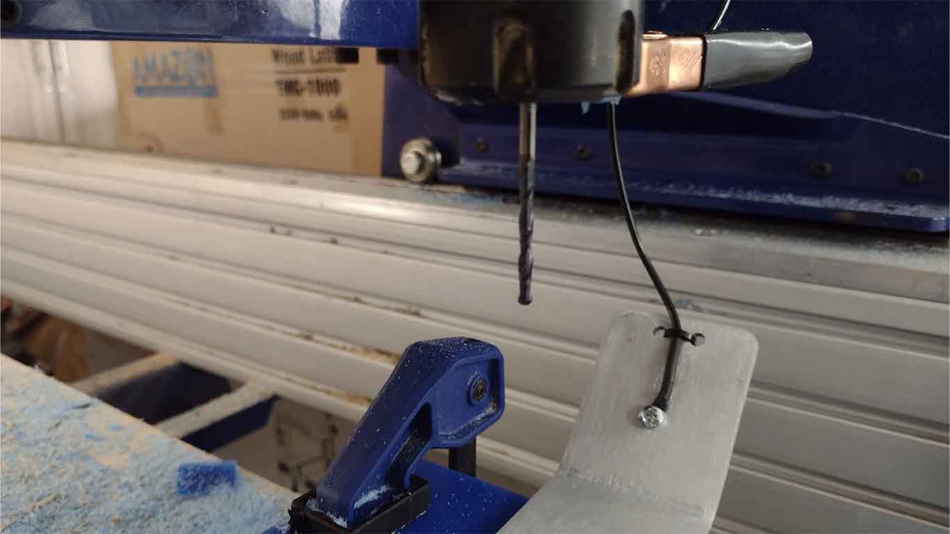
After sending with the SHOPBOT program, I could see that the machine began to carry out the FINISHING process of my mold where the milling cutter traveled all the trajectories that we saw in the MODS CE. Here is a photograph when I was doing the X axis.
And here is a photograph when he started finishing on the Y axis.
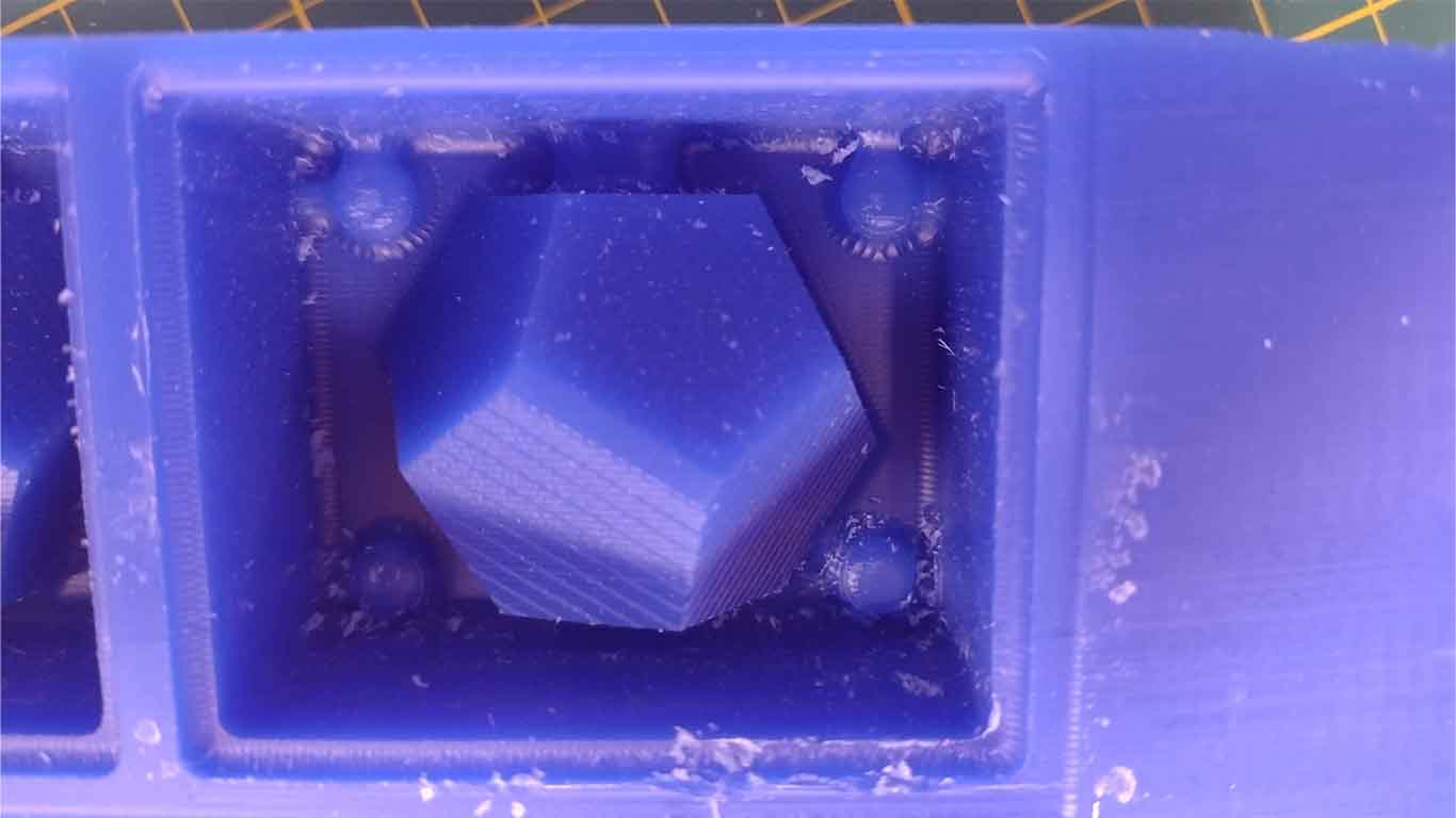
Here's a photo of how the finish of my mold looked after 1 hour and 20 minutes.
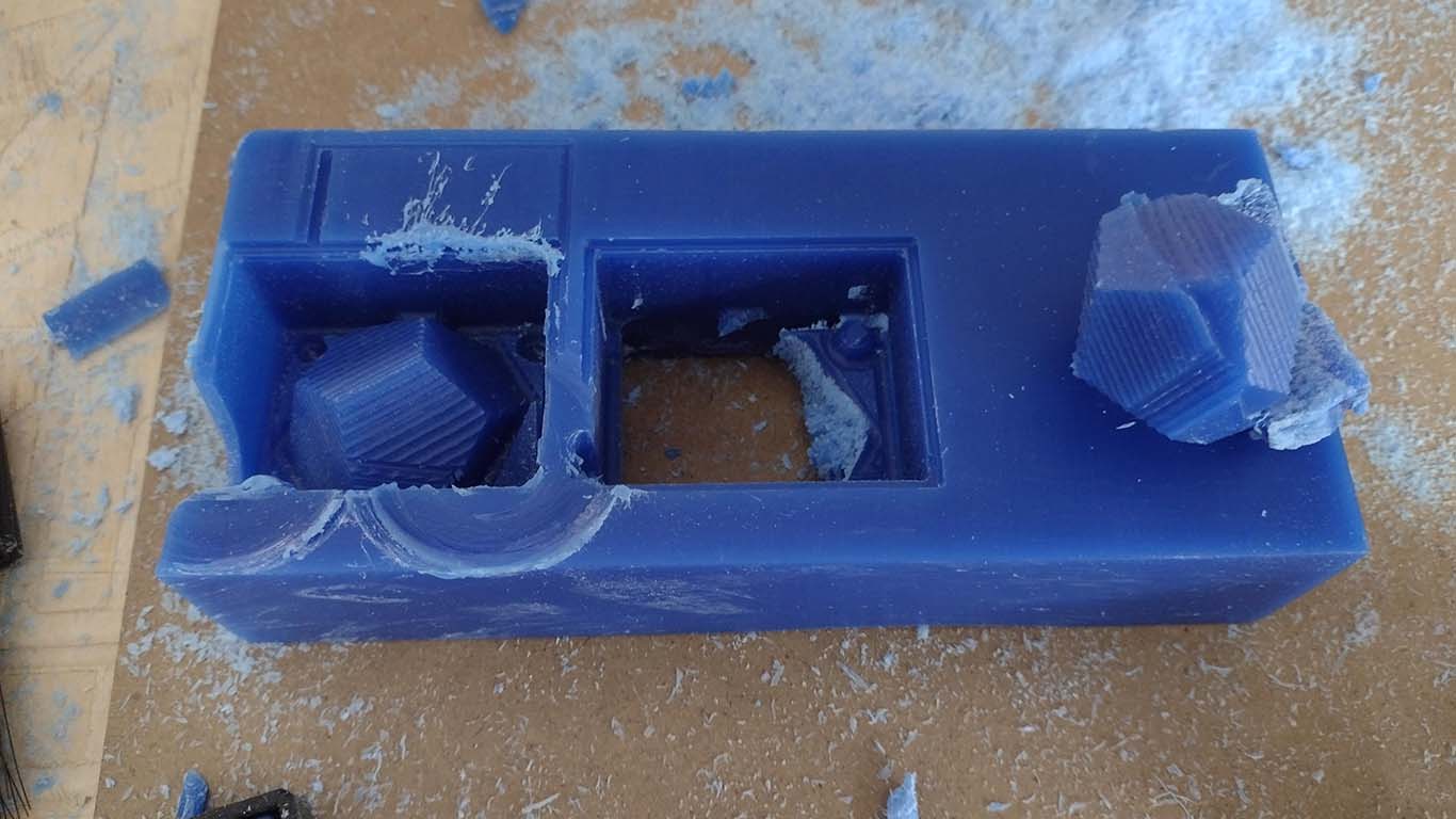
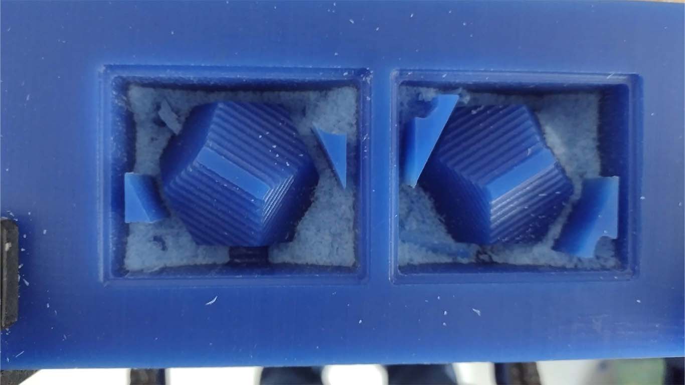
Checking my mold in detail I could see that there were some areas that had not been cut according to the design of my mold. This is because due to the width of the cutter and the small distance from the perimeter of the mold, the cutter cannot travel there.
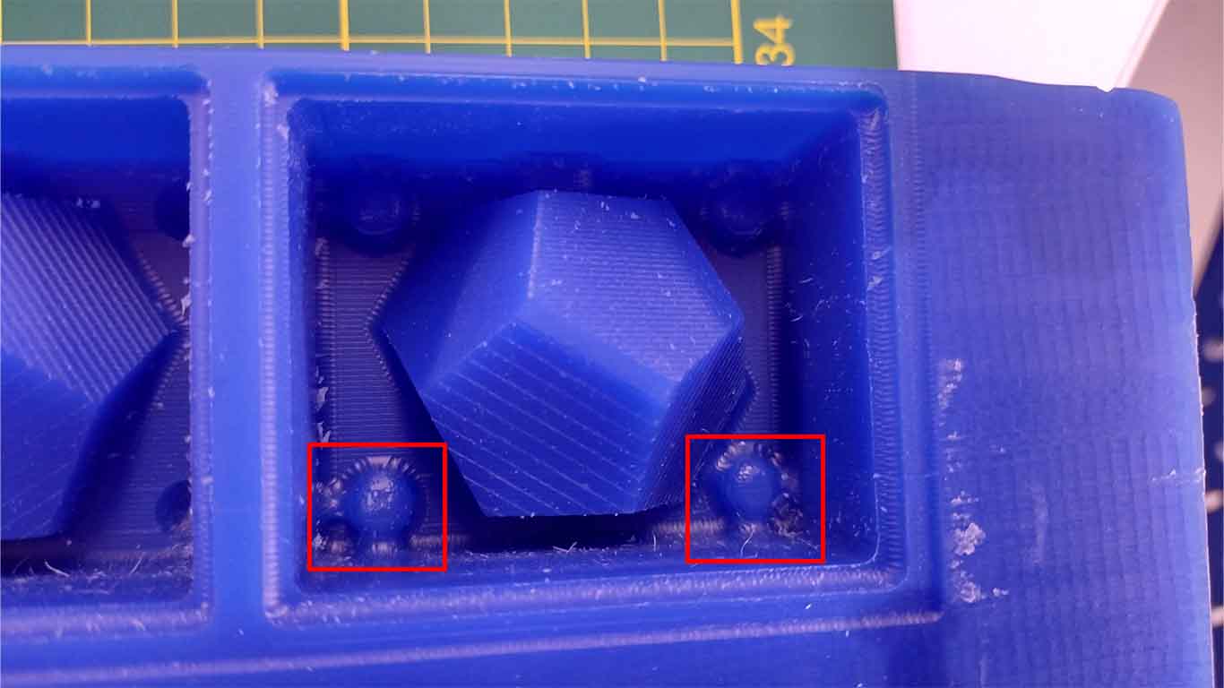
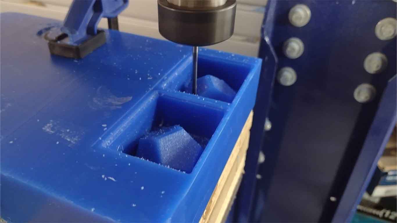
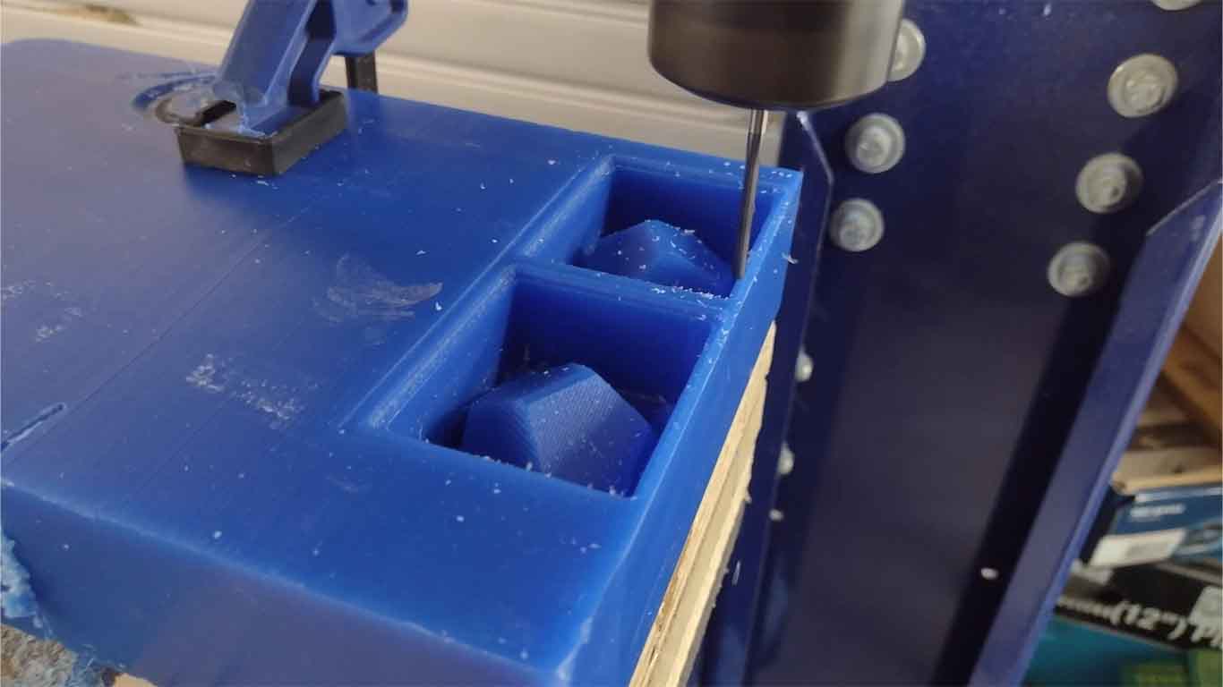
To find a solution to this, I had to resort to what Adrian Torres did in his documentation, which is to cut out these mounds of wax that were left using a drill. So I started doing the same.
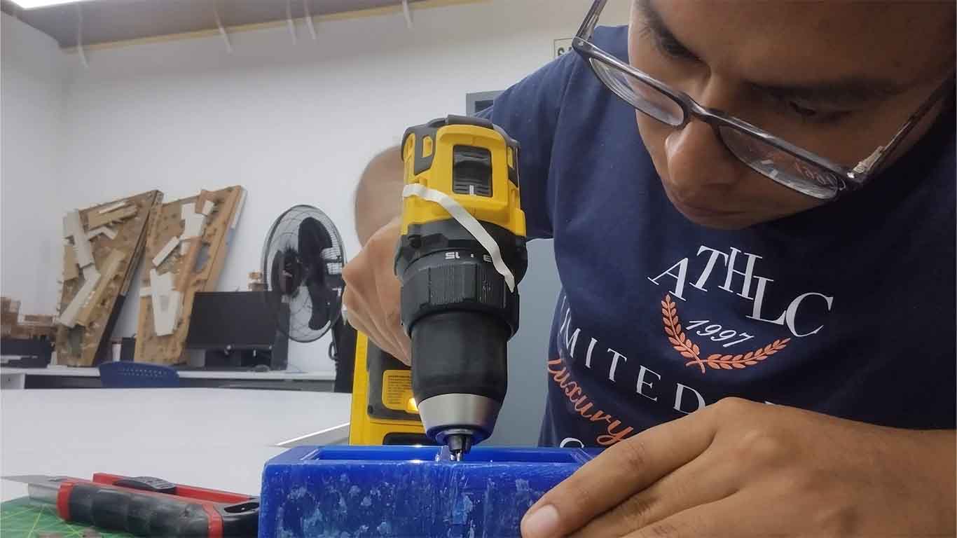
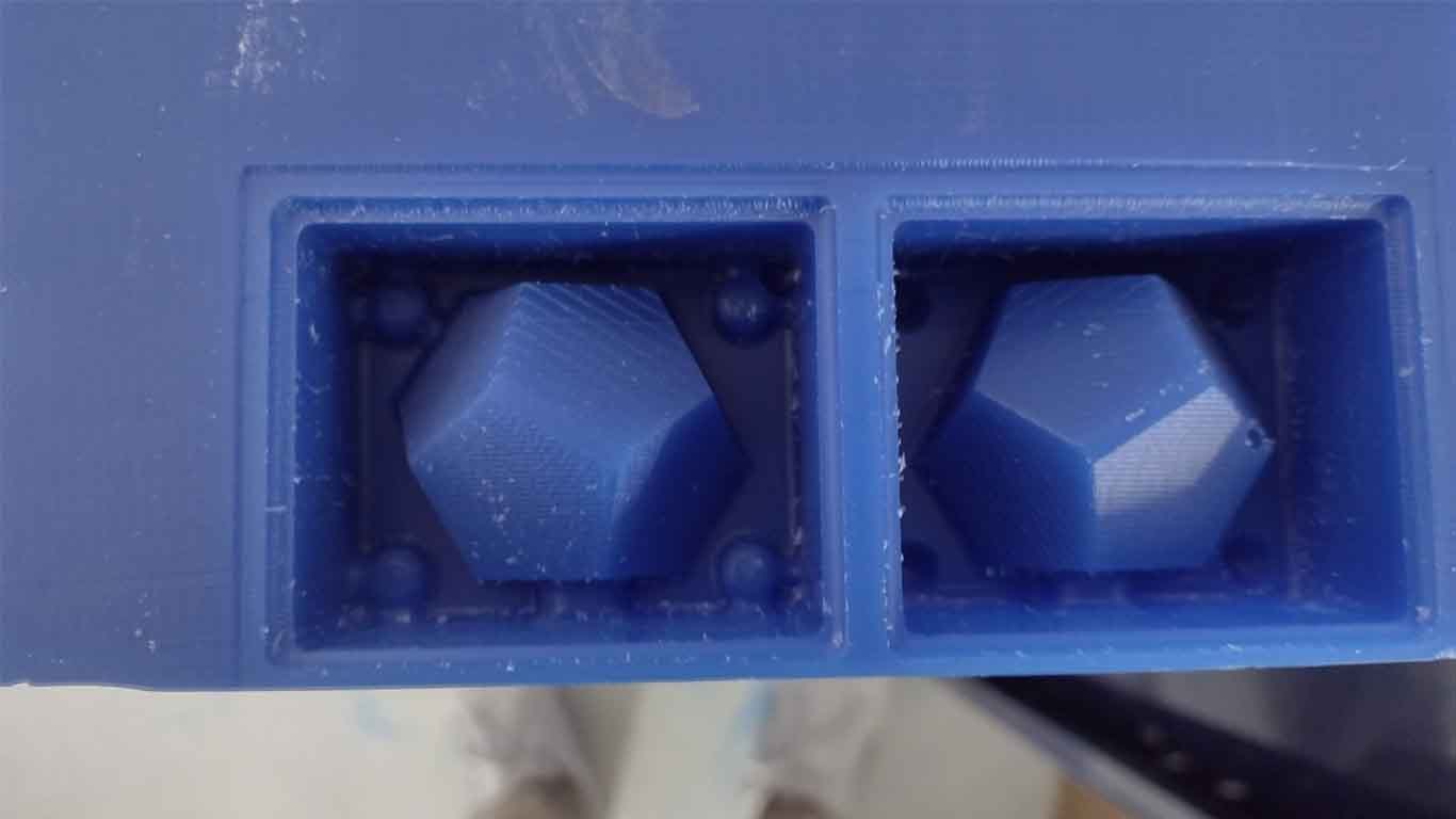
Finally, I was able to do a good cleaning of these wax mounds and it was ready to carry out the step of obtaining the final mold with silicone.
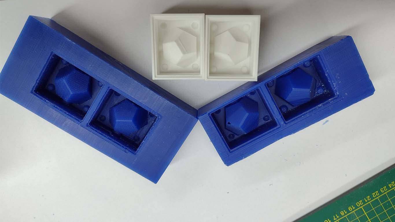
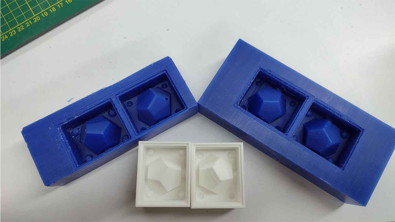
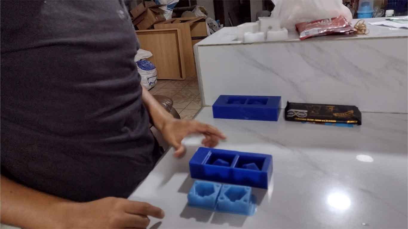
Here is a photograph of my wax and my final 3D print to receive the silicone mold process.
SILICONE MOLD
To make my molds I used 2 silicones that I found very interesting due to their characteristics obtained after carrying out the tests. Here the process of making the mold with each of them.
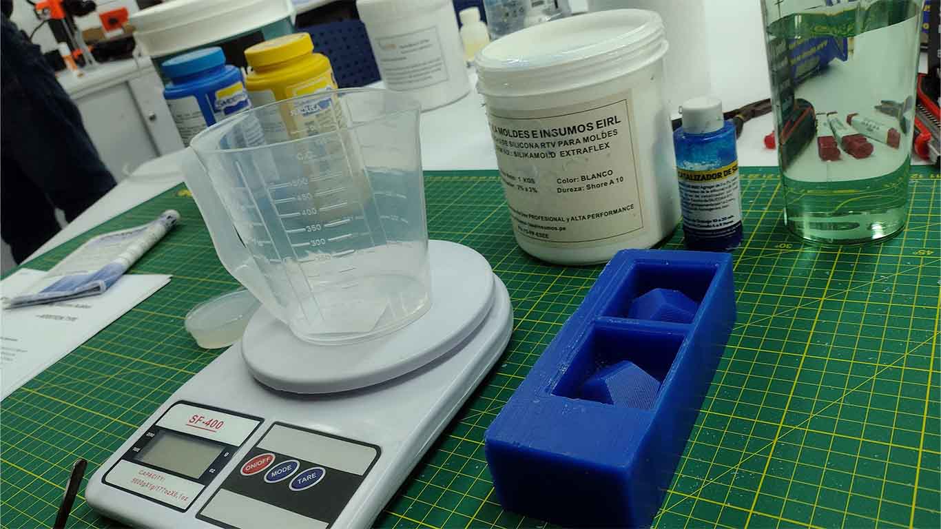
SILICON RTV EXTRAFLEX
First I prepared all the supplies I would need such as the mold, silicone, catalyst, water, weight and a jar with a measure to control the portions. I will use this silicone in my wax mold.
First, to measure the amount of silicone I was going to use for my mold, I used water and put it in my mold until I filled it to the maximum on both sides.
After filling them, I poured the water into a jug to obtain the exact size of silicone I would need to make my mold.
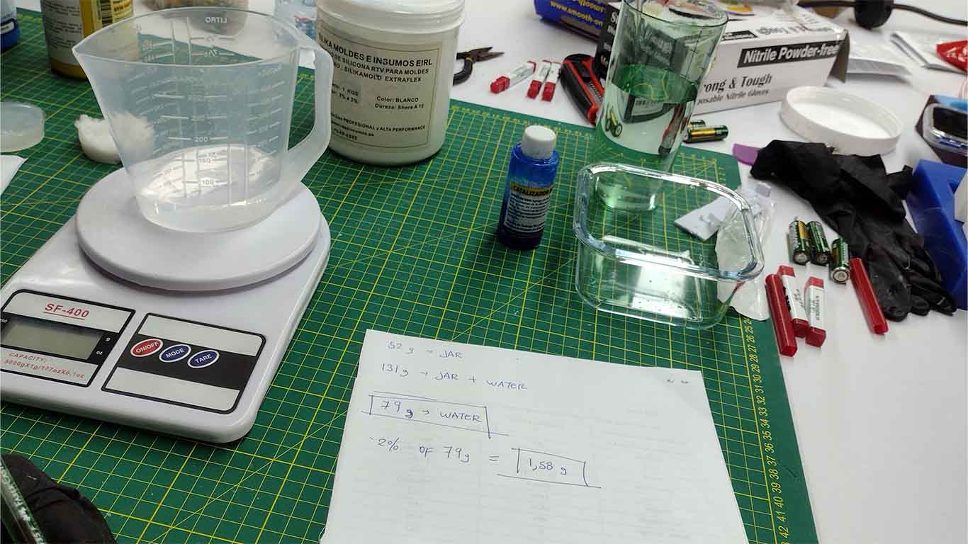
Before starting with the silicone, I forgot to just weigh the jar I'm using in grams. So I poured the water from my mold into another container and started measuring the jug alone, where we can see that it weighs 53g.
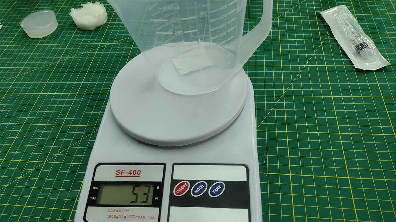
Then I poured the water from my mold back into the jar and we can see the weight increased to 131g. Here are some screenshots of my calculation carried out to know the amount of silicone I am going to use and also to know what amount of catalyst I was going to use.
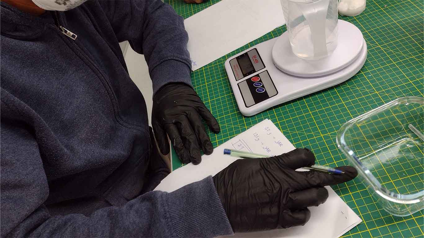
Here we can summarize my calculation of how much silicone I was going to use and the catalyst portion. For this case, I am going to use 79g of silicone and according to the proportion suggested in the silicone data sheet, 2% of 79g I am going to use for the catalyst.
After knowing the appropriate proportion to have a perfect mold, I started to open the silicone and pour into the jar until reaching the measurement shown above.
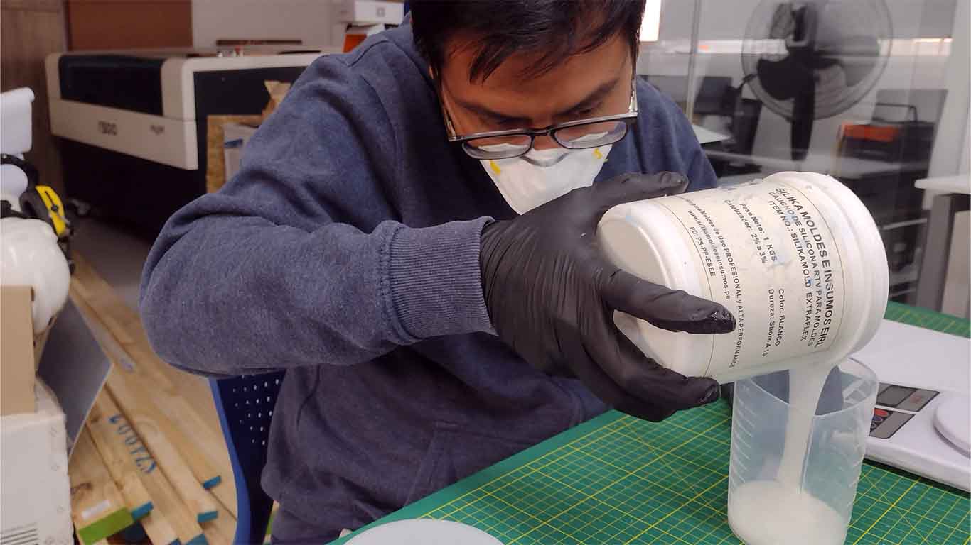
Here is a screenshot of the amount of silicone I am using according to the calculation made and measured in the jar.
Then I opened the catalyst to calculate the portion of 2% that I had to use to pour it into the silicone as previously measured, here are some photographs of the process of pouring the catalyst into the silicone.
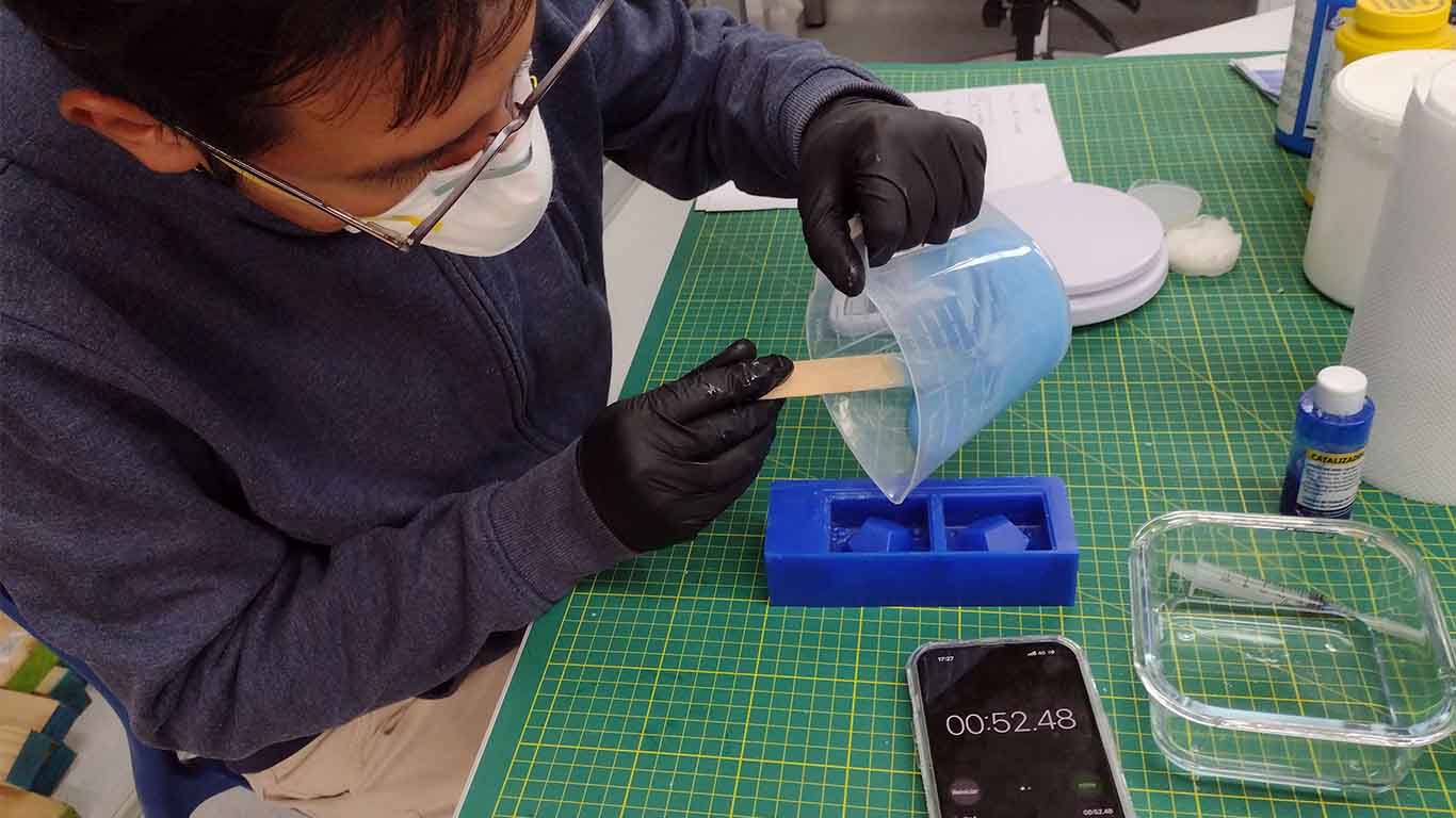
After pouring the catalyst into the silicone, I begin to mix constantly and not so quickly to avoid generating too many bubbles, until I obtain a homogeneous mixture. Let's remember that we have a maximum of 3 minutes of mixing to pour into my wax mold since it is mentioned in the product data sheet.
Here my colleague Silvana supported me by setting a timer to calculate the time and avoid missing the important time.
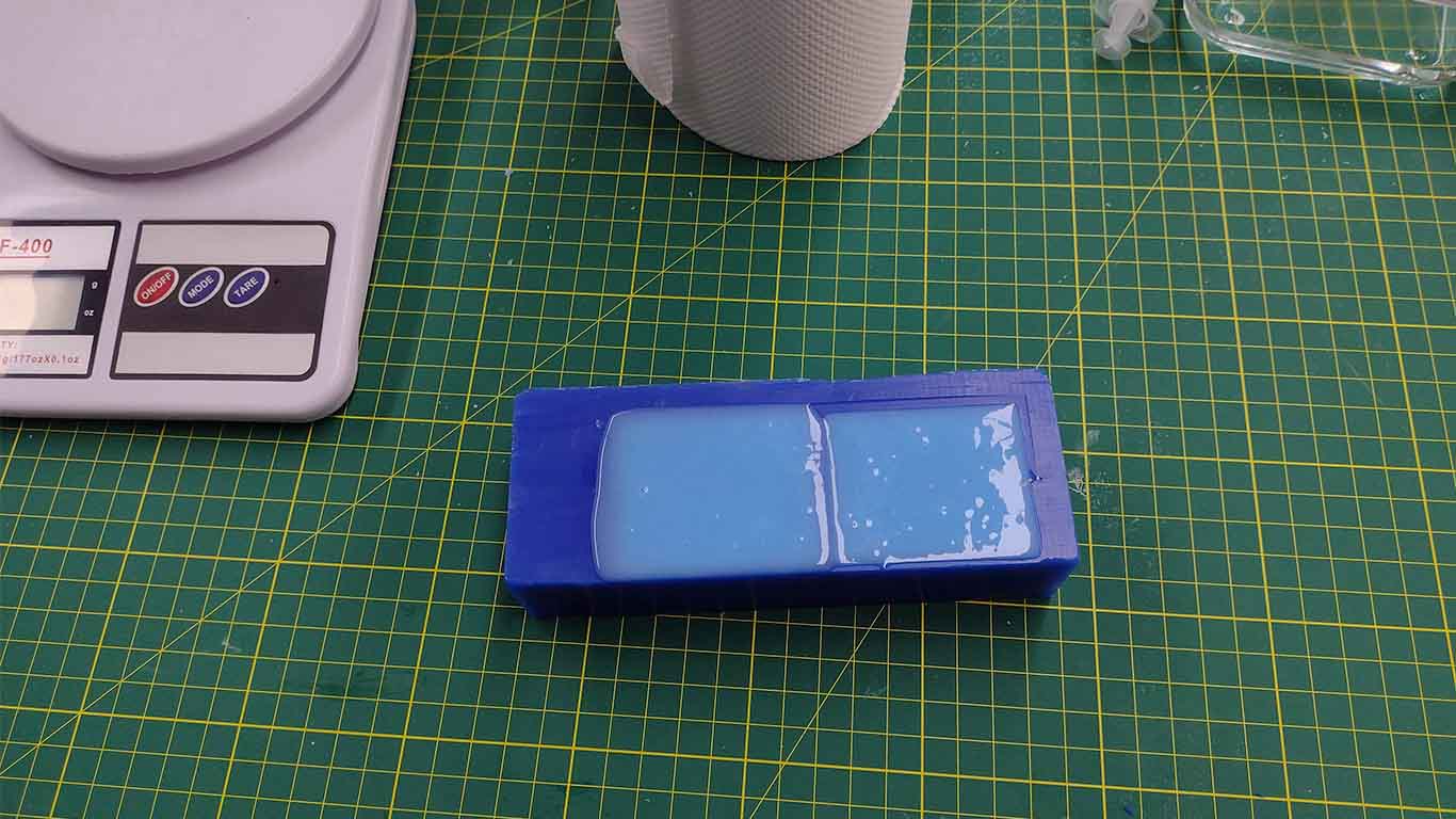
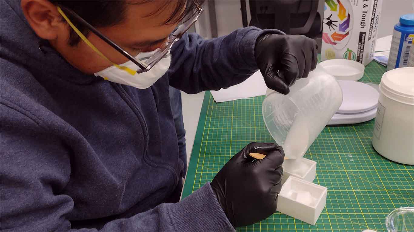
After mixing for the indicated time, I began to pour the wax into the mold. Here are some photographs of the process of pouring the silicone into my mold.
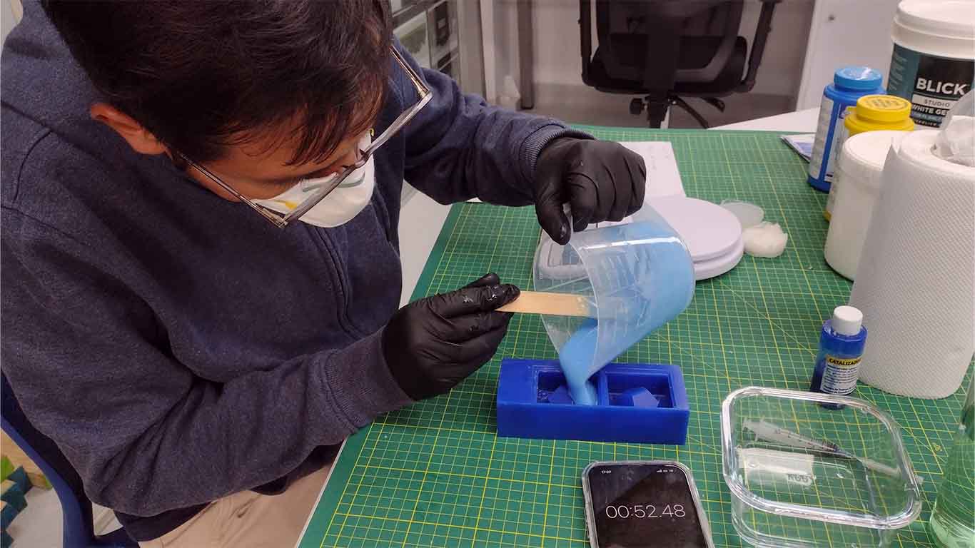
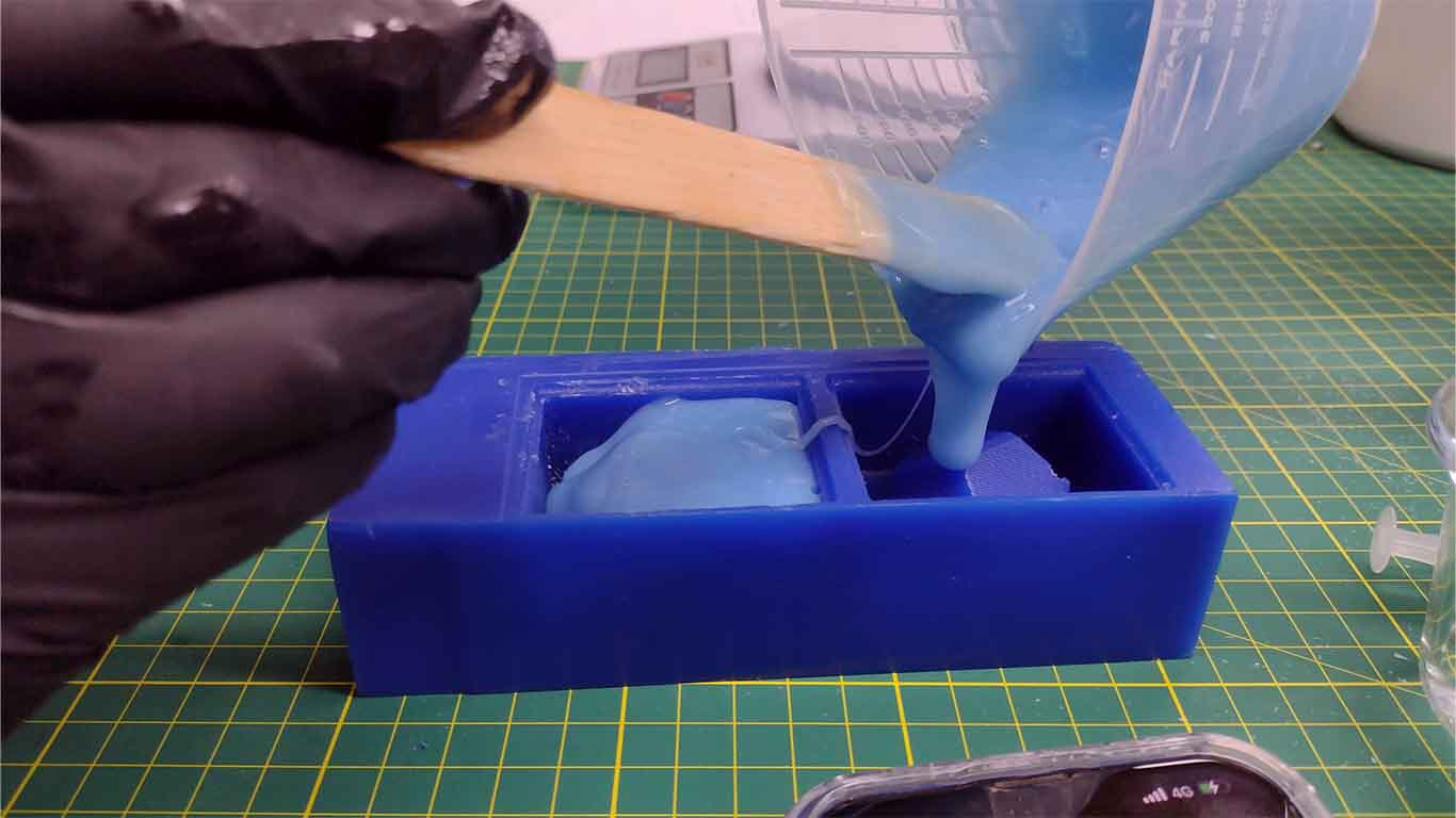
I could see that the calculation of the portion for my mold was exact and according to the measurement I made in a previous step. This is important to avoid having more silicone and wasting it. In my case, the measurement was exact and I didn't have any silicone left over in the jar.
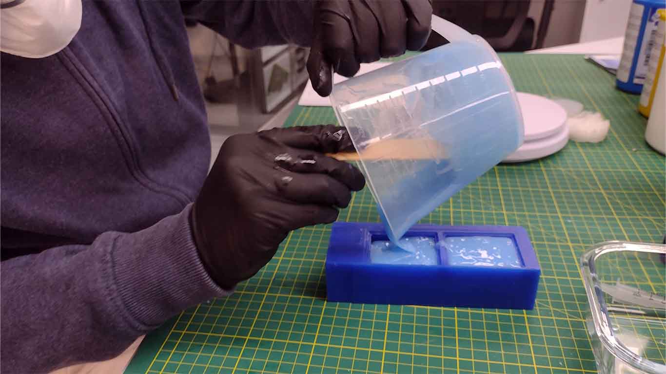
Finally, as a recommendation from my friend Silvana, she told me to lightly tap it against the table to eliminate some bubbles that are generated in the silicone and I began to do it until some bubbles disappeared from the silicone and then I sent it to put it away until I waited for the indicated time. curing.
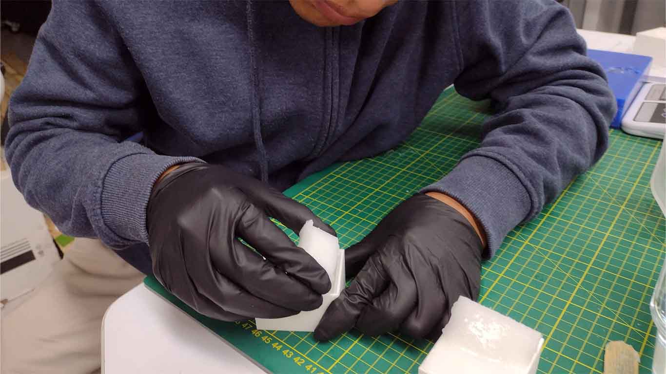
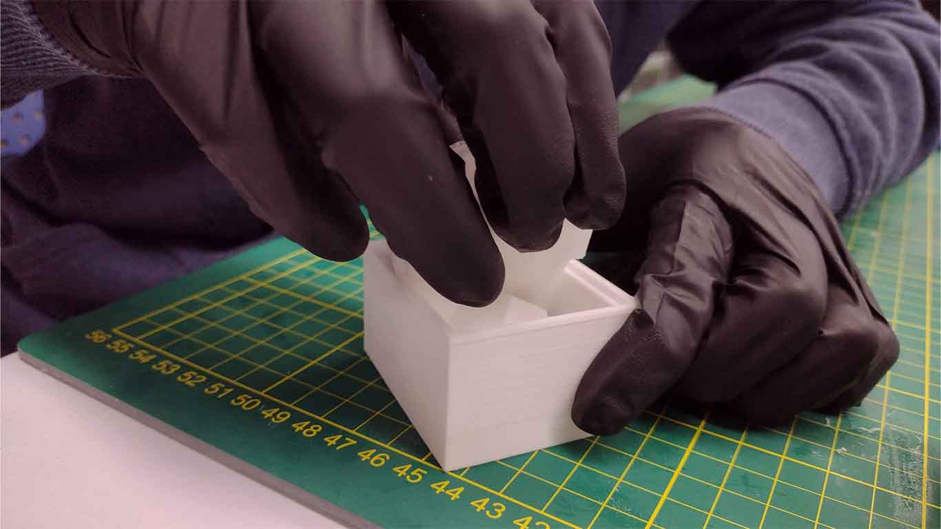
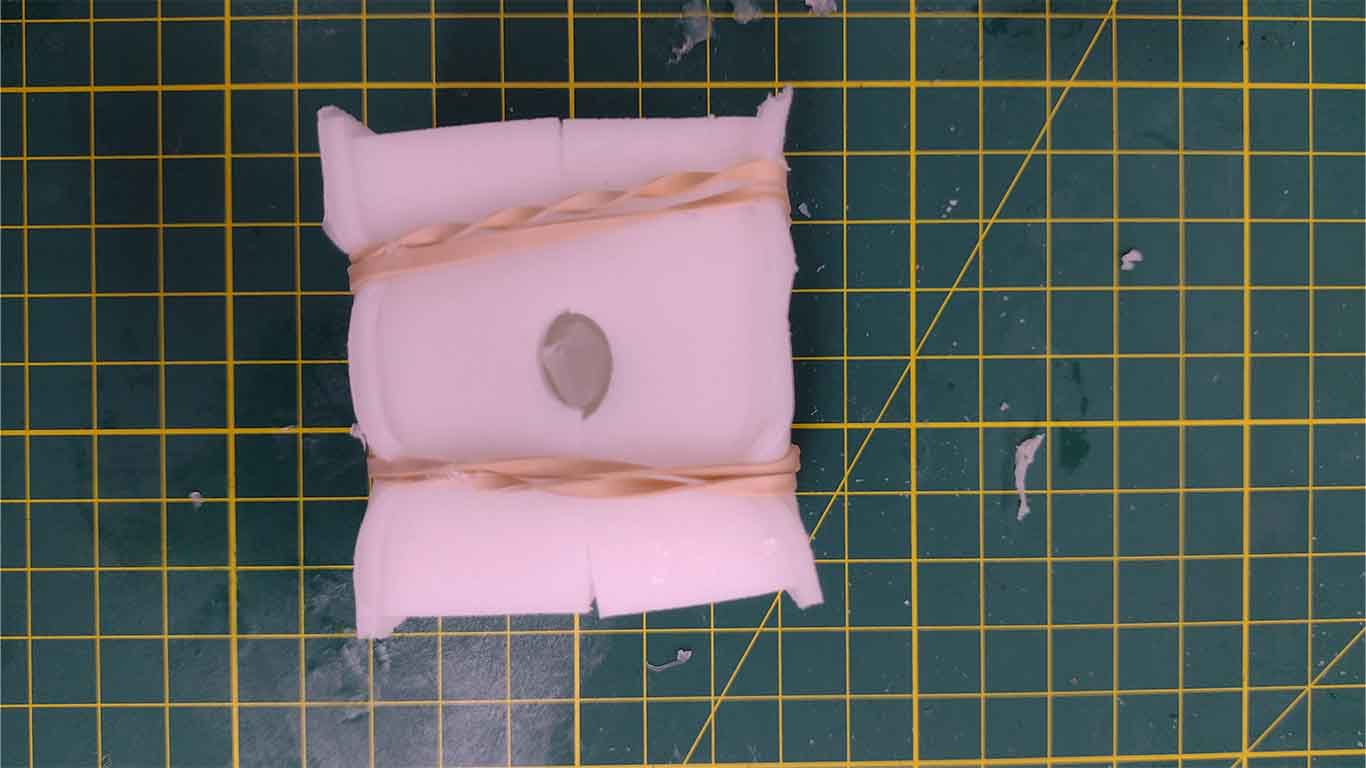
After approximately 12 hours, I unmolded the silicone and it went very well, without any breakage problems and everything was fine, ready to receive different castings.
Here is a close-up photograph of the mold and the silicone obtained.
SILICON F10 PLUS
I will use the next silicone in my 3D printing molds. The steps are similar so I will summarize a little the process I carried out.
First, to know the amount of silicone I was going to use, I started pouring water to calculate the number of grams I was going to use for each mold.
Then I poured all the water into the jar to obtain an exact measurement for each mold and we will proceed to carry out the process of weighing and calculating proportions that is according to the product data sheet.
After that, I began to pour the F10 silicone into the jug according to the calculation made of proportions and milliliters.
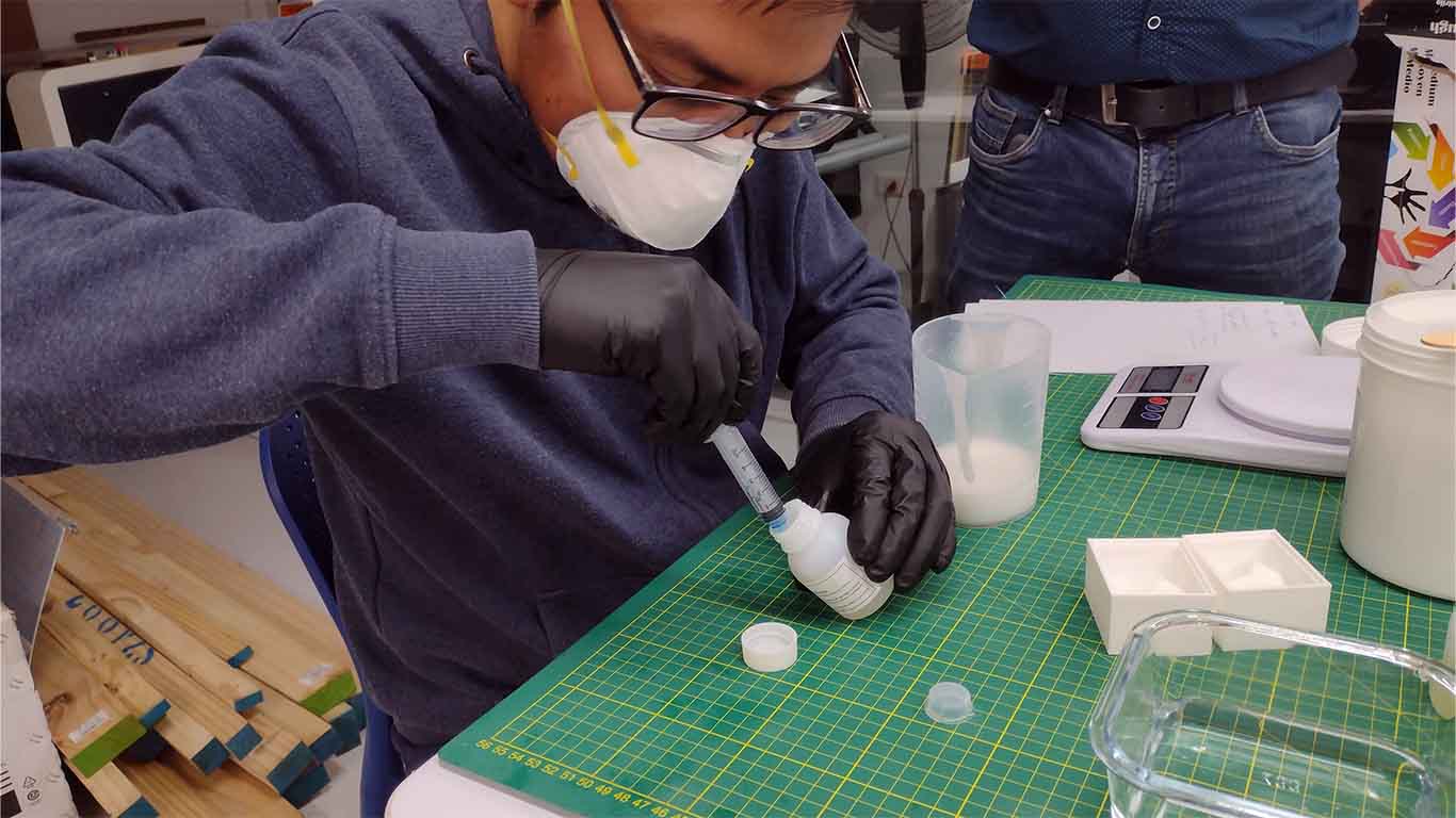
Then, with the help of a syringe, I calculated the catalyst and had the appropriate amount in milliliters for the amount of silicone I am going to use.
I began to mix both liquids to obtain a homogeneous mixture for the number of minutes that we have in the technical specifications.
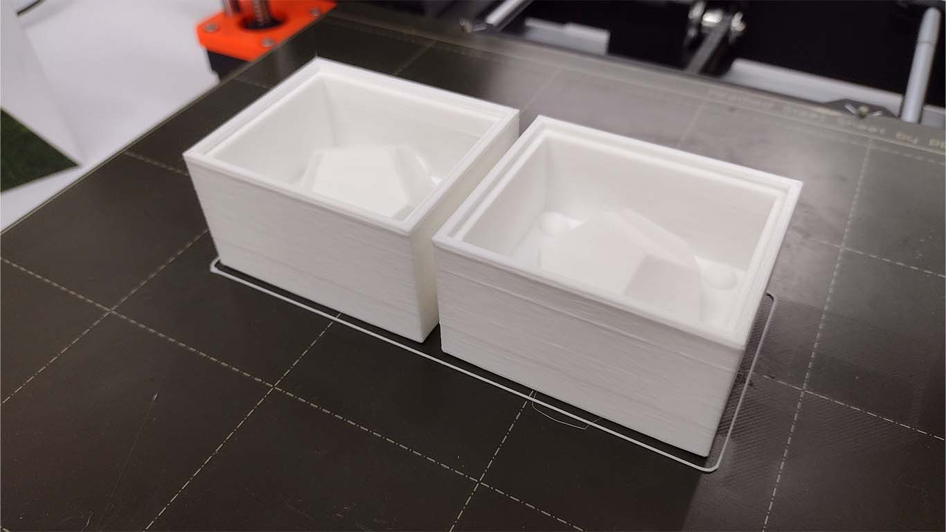
Then I started pouring the silicone into my 3D molds and like the previous mold, there was not much silicone left over since the calculation was doing well.
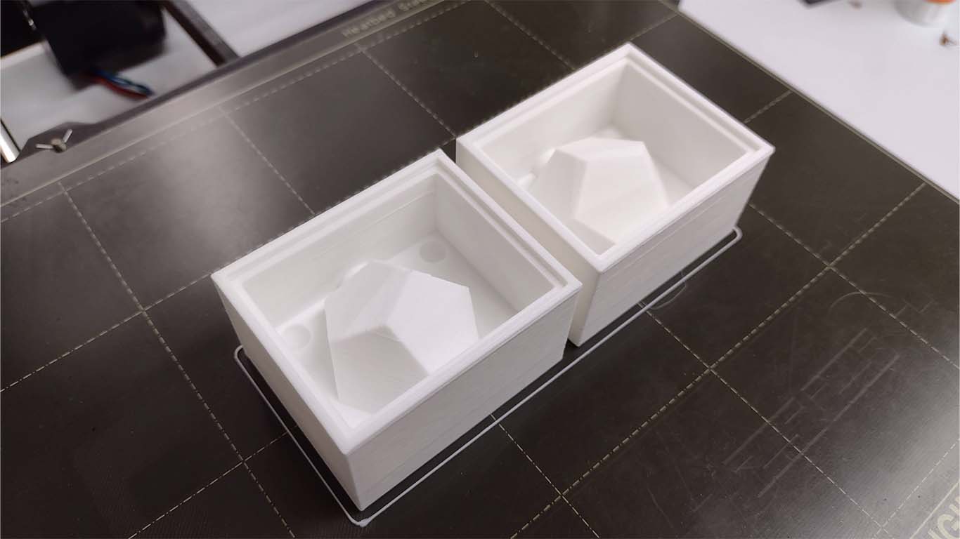
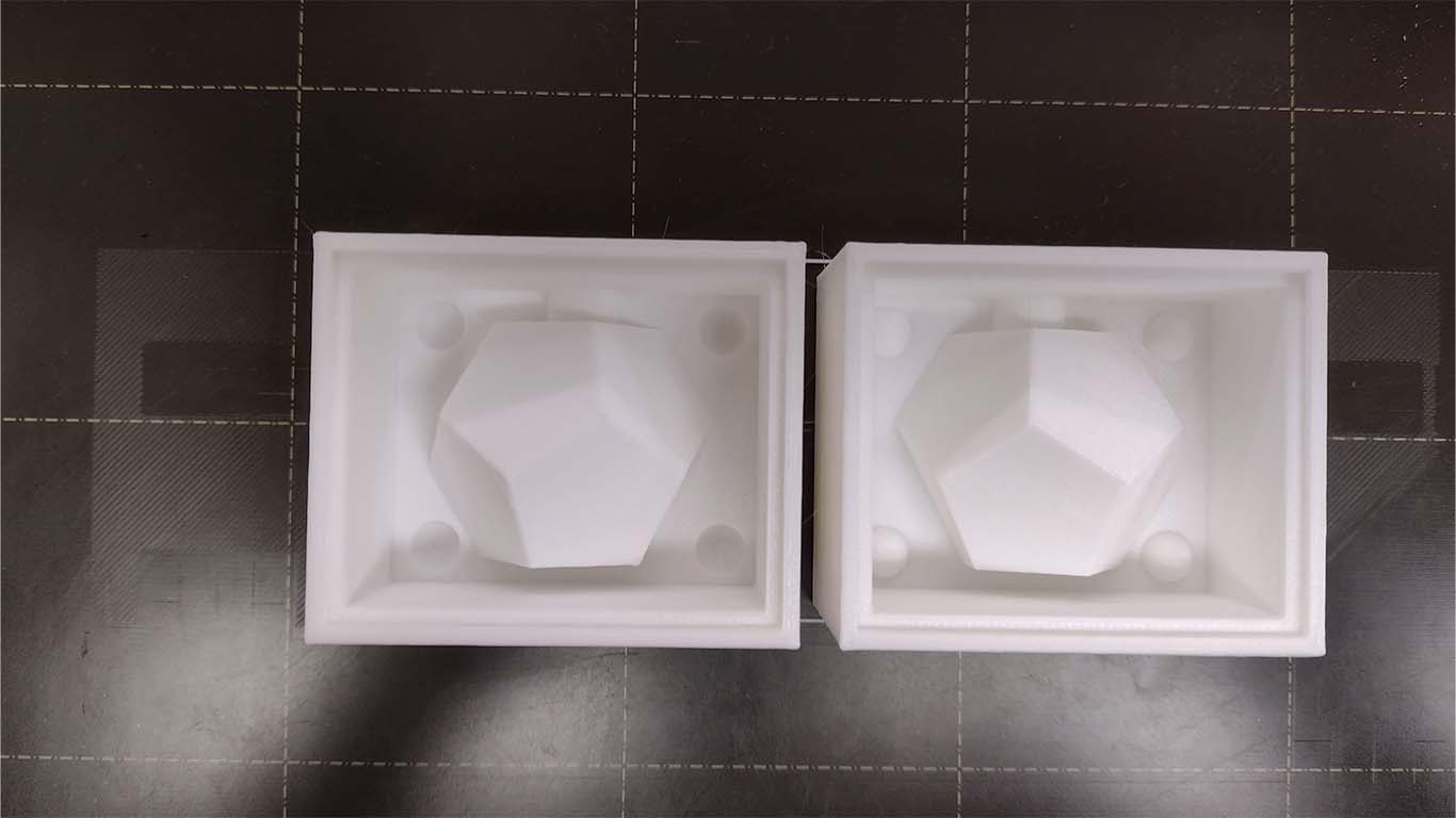
Finally, here is a photograph of how my molds look ready for curing.
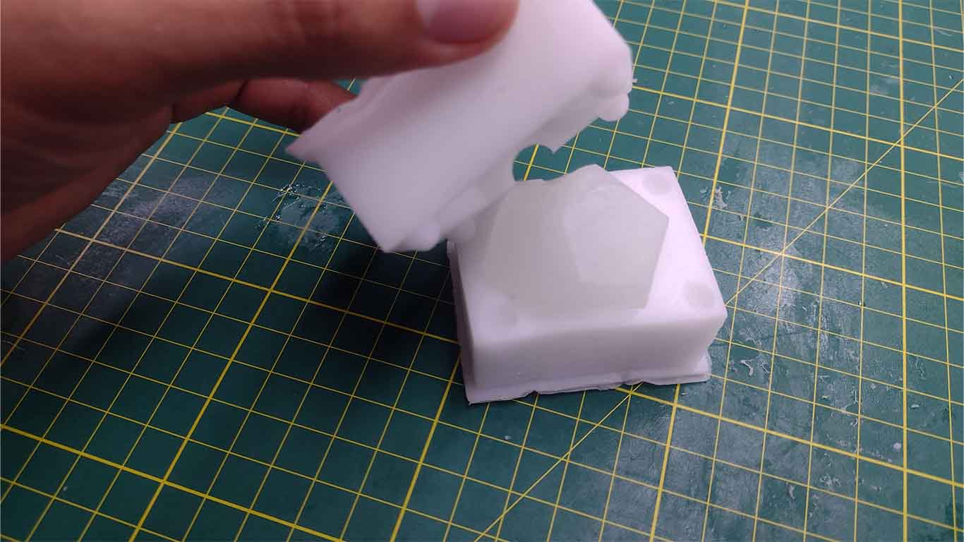
After the curing hour had passed, which was approximately 8 hours, I began to remove the mold from my 3D print and it went very well, I had no problems with removing it and no problems with breaking the silicone.
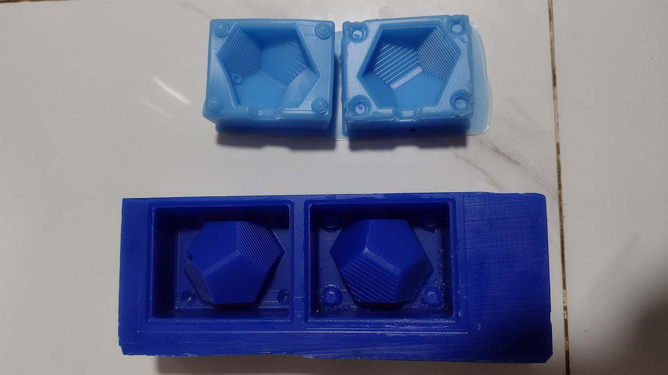
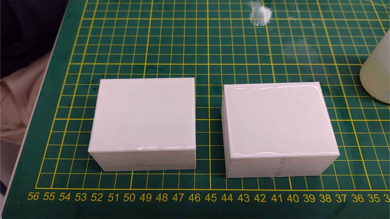
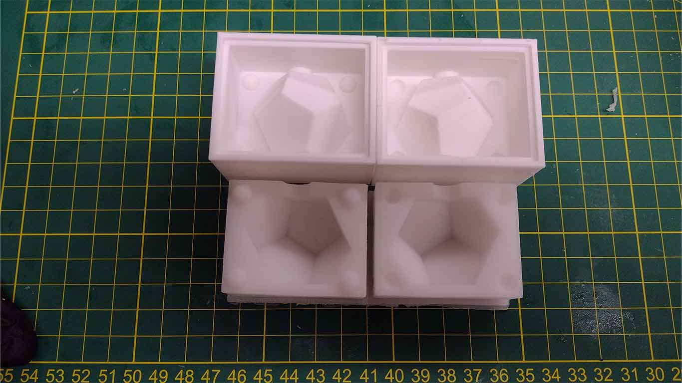
Here is a final photograph of my 3D printing and my F10 silicone mold, it came out very well and ready to cast dodecahedra with the mold.
CASTINGS
CHOCOLATE
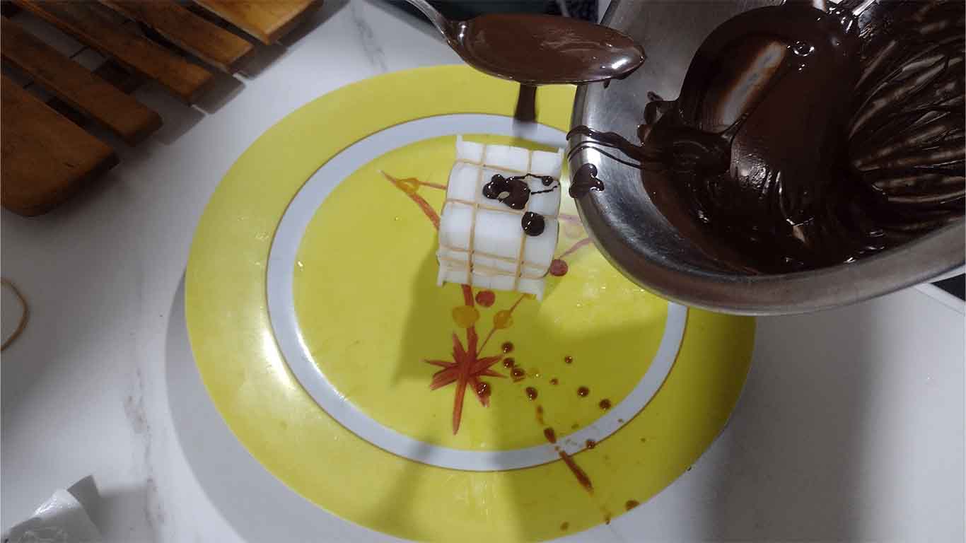
The funniest and sweetest moment of the assignment has arrived. For this case, I started casting with chocolate. Here is the process of how I did it and the result.
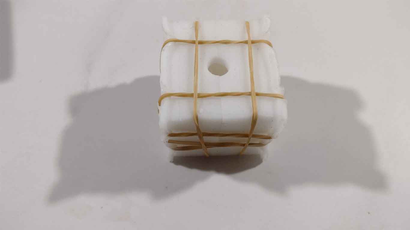
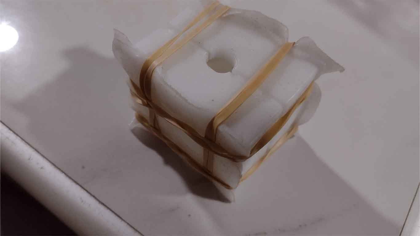
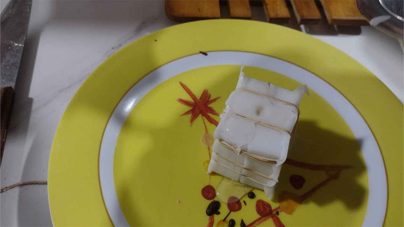
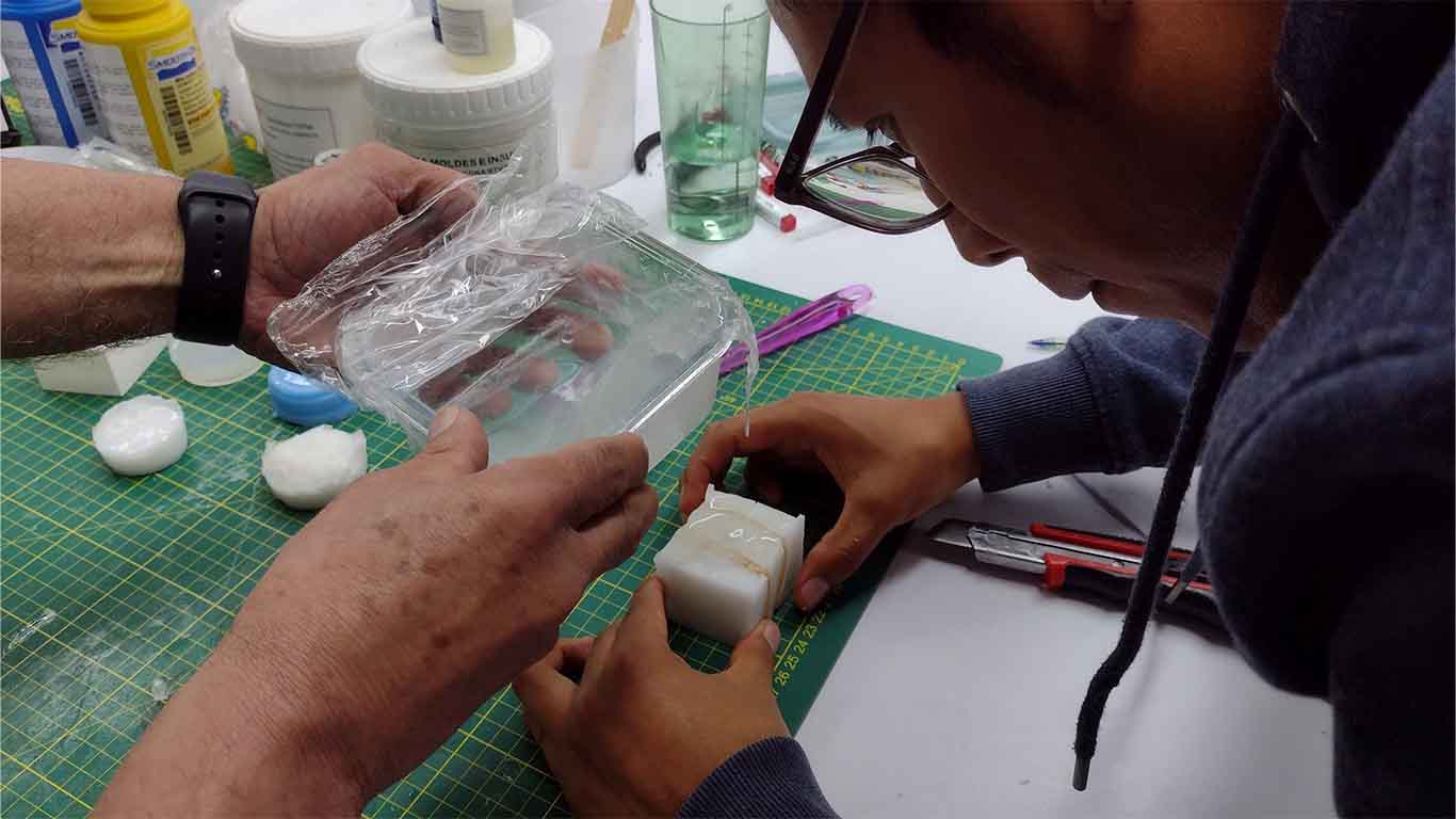
First, I prepared my mold with rubber bands that were recommended to me so that it would not open or leak.
To make the chocolate melt, we have to do the popular BAÑO MARIA technique, where in a container we make contact with hot water in a pot or other container and this will heat up until little by little the chocolate melts.
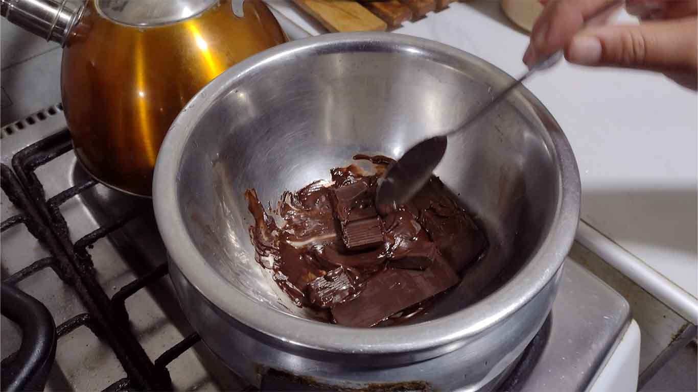
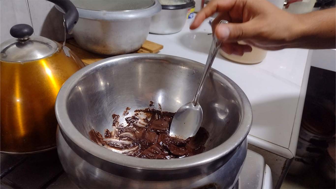
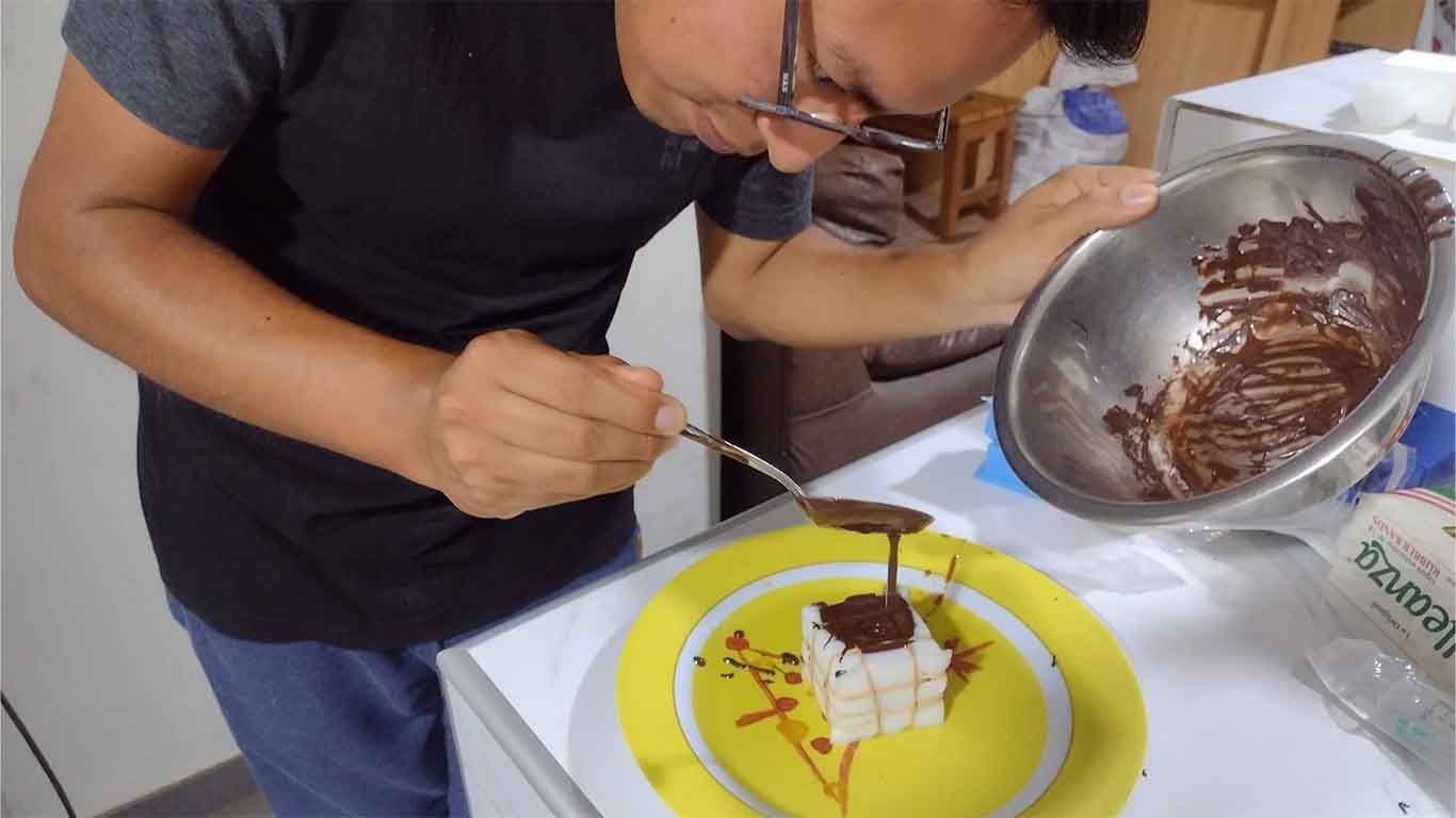
After melting the chocolate very well until it had a homogeneous texture, I began to carefully pour it into the mold. I had to press and tap the mold so that the chocolate can get into all the corners of the mold.
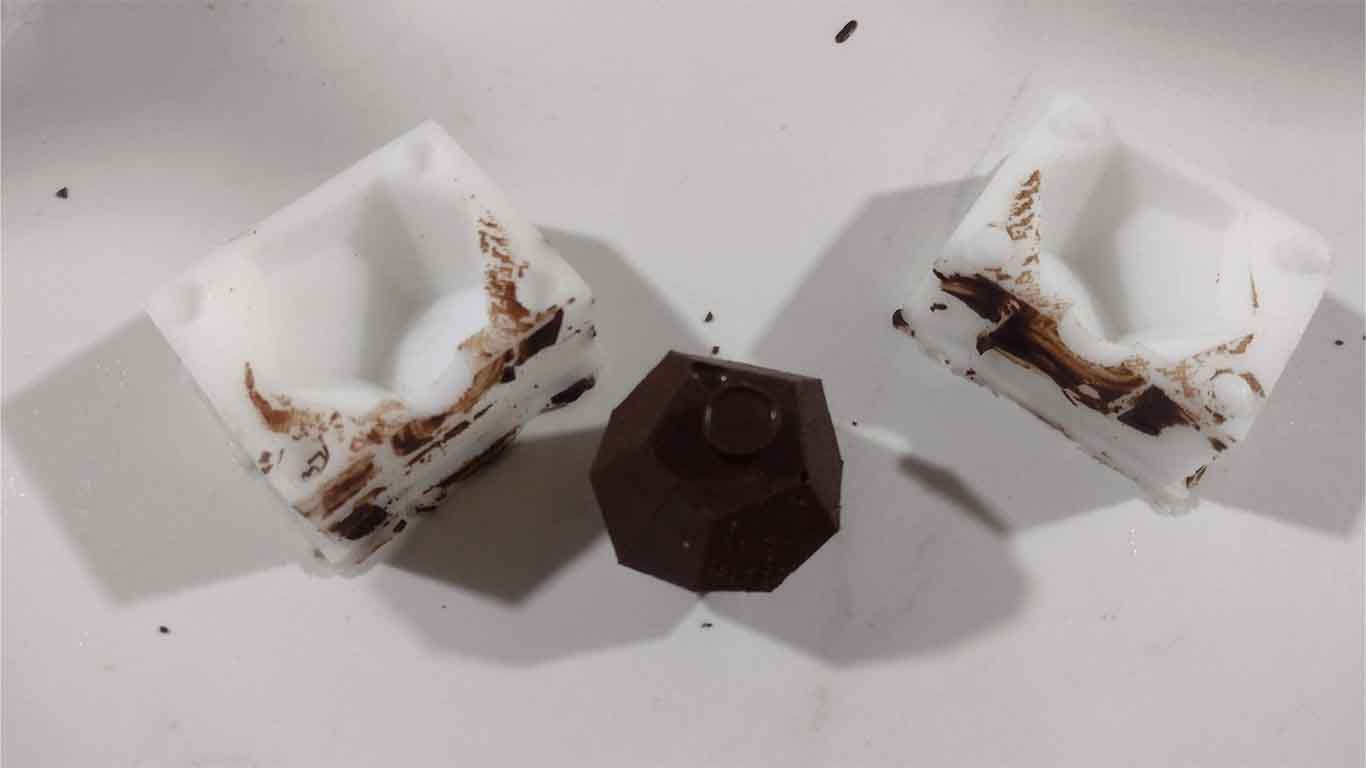
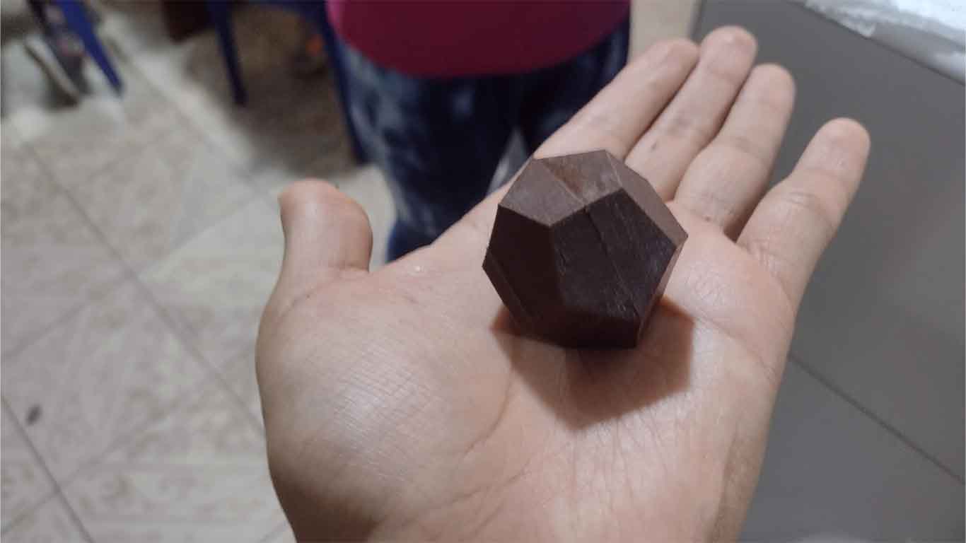
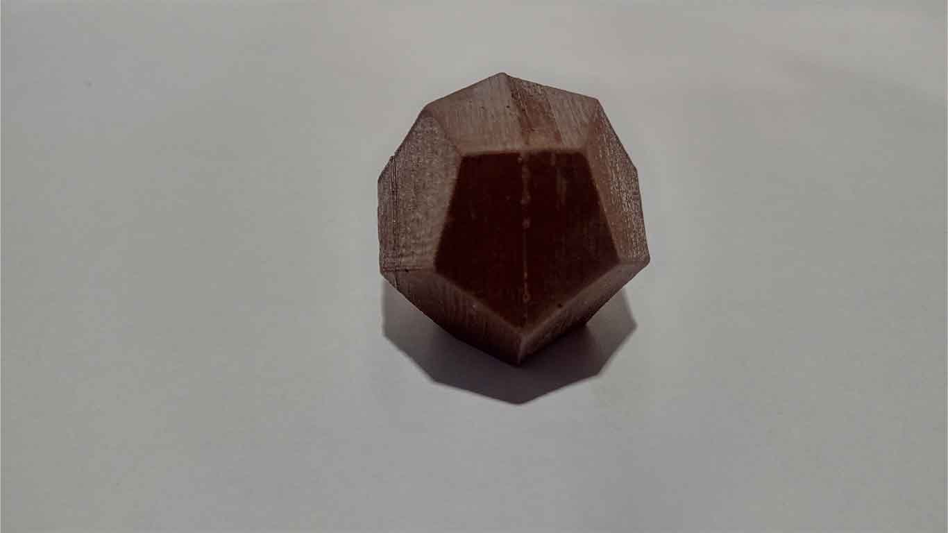
After waiting until the chocolate cooled, more or less 3 hours, I began to unmold and observed that the result is impressive, the chocolate obtained the shape that I had designed. Here are some screenshots of the result.
“BURNT” SUGAR
"Burning" sugar is a technique that I don't know if many countries do, but it consists of burning the sugar in a pot or container on the stove until it becomes liquid. They use this technique a lot to make sugar candies, they also use it for "calientitos" which is a typical drink from Peru and also for breakfasts like quinoa. Here is the process of how I made a sugar candy in the shape of a dodecahedron.
First, like the chocolate, I put rubber bands on my mold so it wouldn't open or leak.
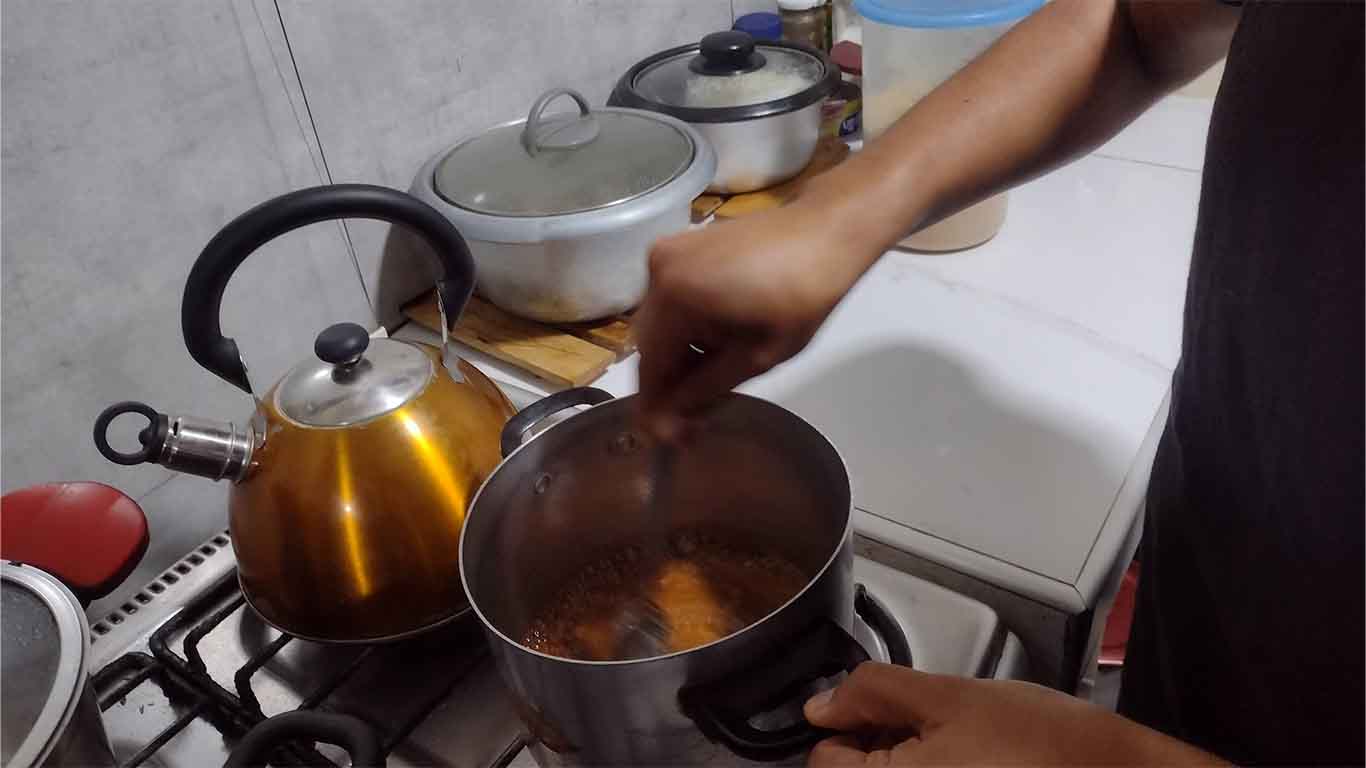
The first thing we do is put the amount of sugar we will need in a pot. We have to move this until it becomes liquid. We have to be careful because this liquid is very harmful to the skin.
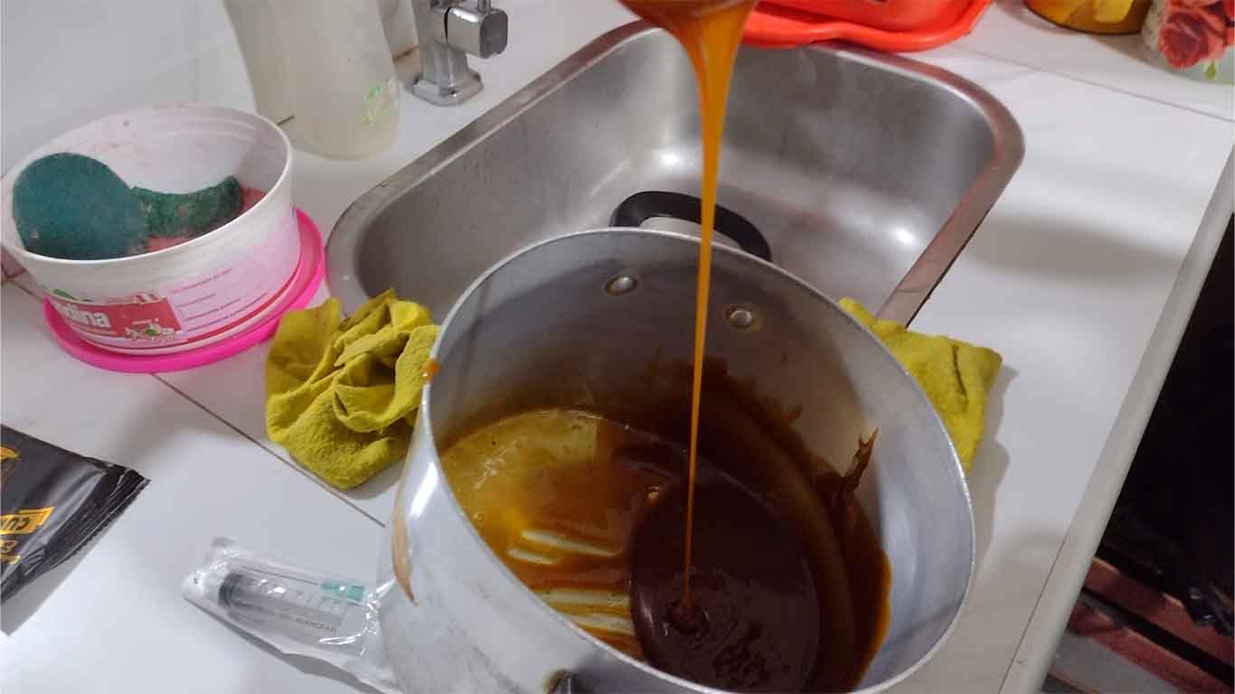
Here is a photograph of how liquid the sugar should be, remember that we must be moving it so that it does not stick to the pot.
Finally, after having a good amount of liquid, we pour it into our mold with the help of a spoon and begin to fill it.
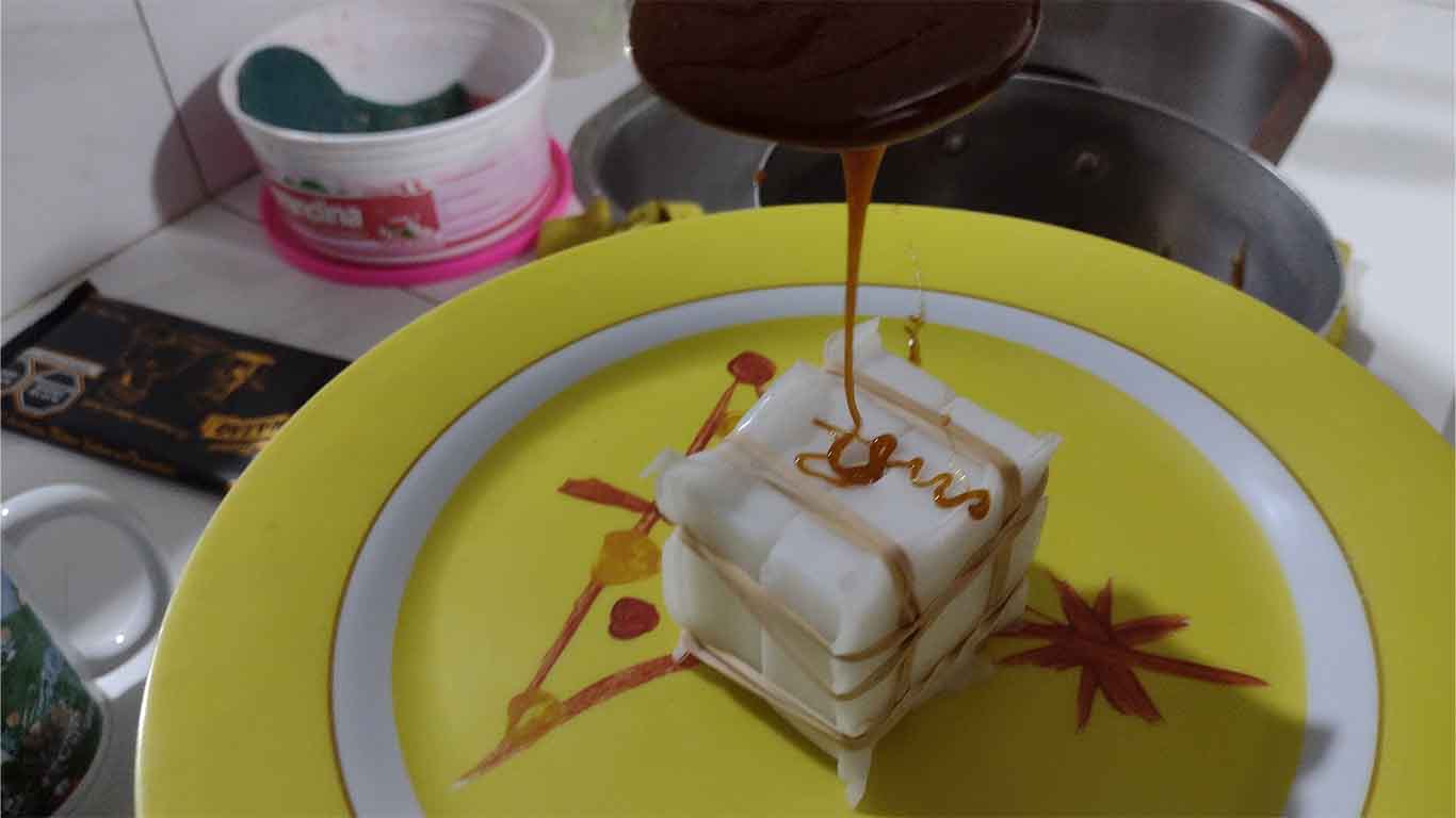
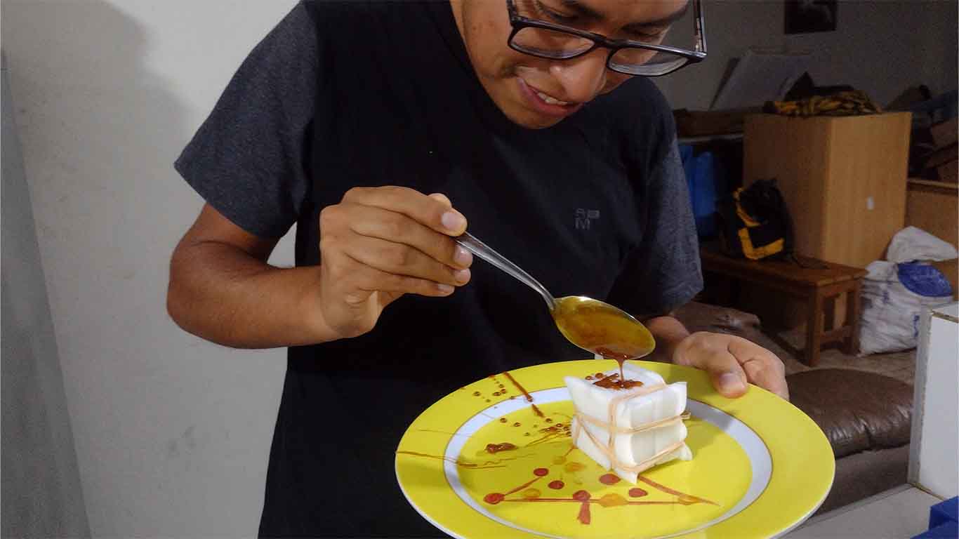
The drying of the caramel is fast, where in half an hour we can have the result, in my case I waited approximately 1 hour to see the result. Here are some photographs of the result.
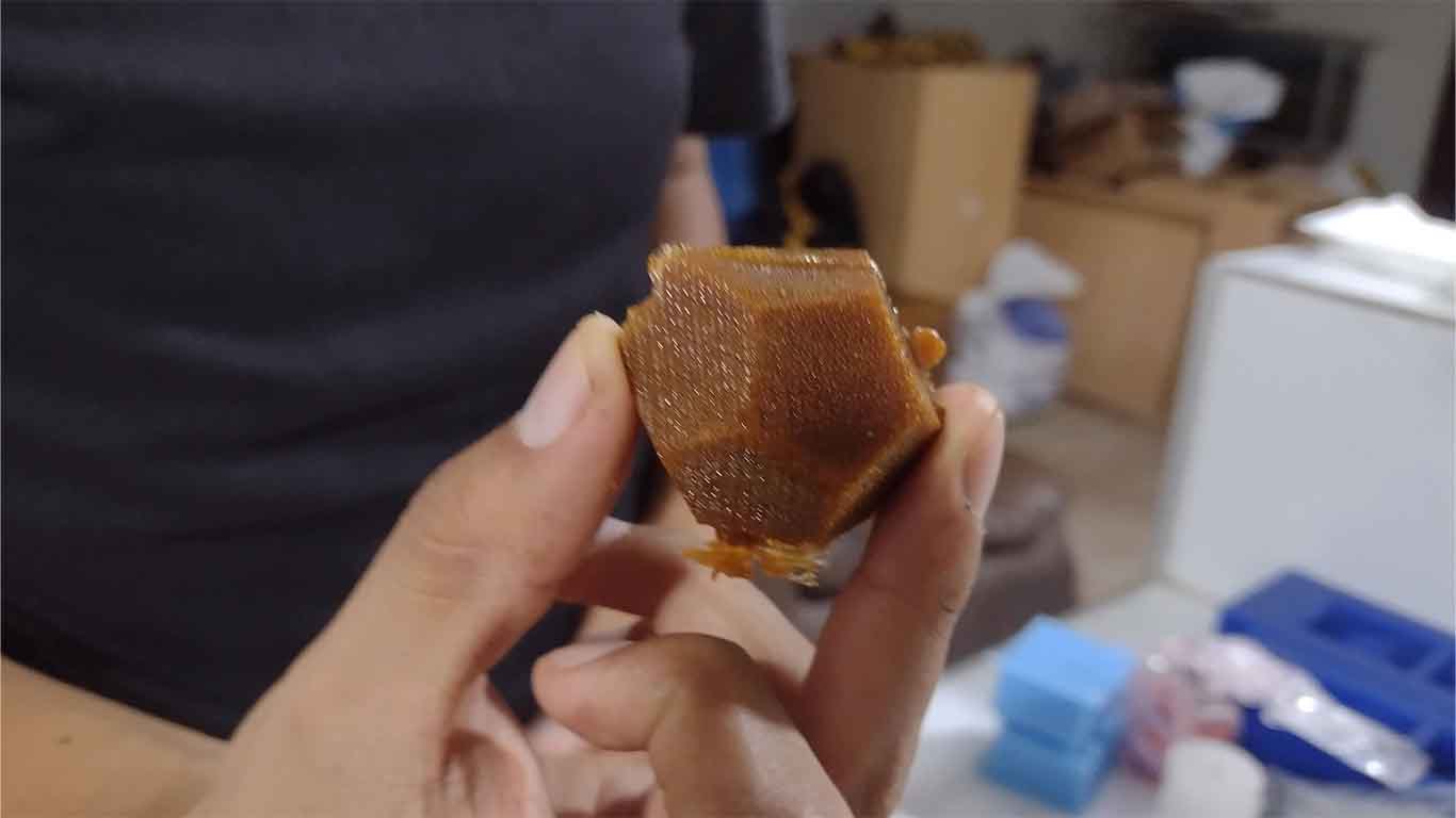
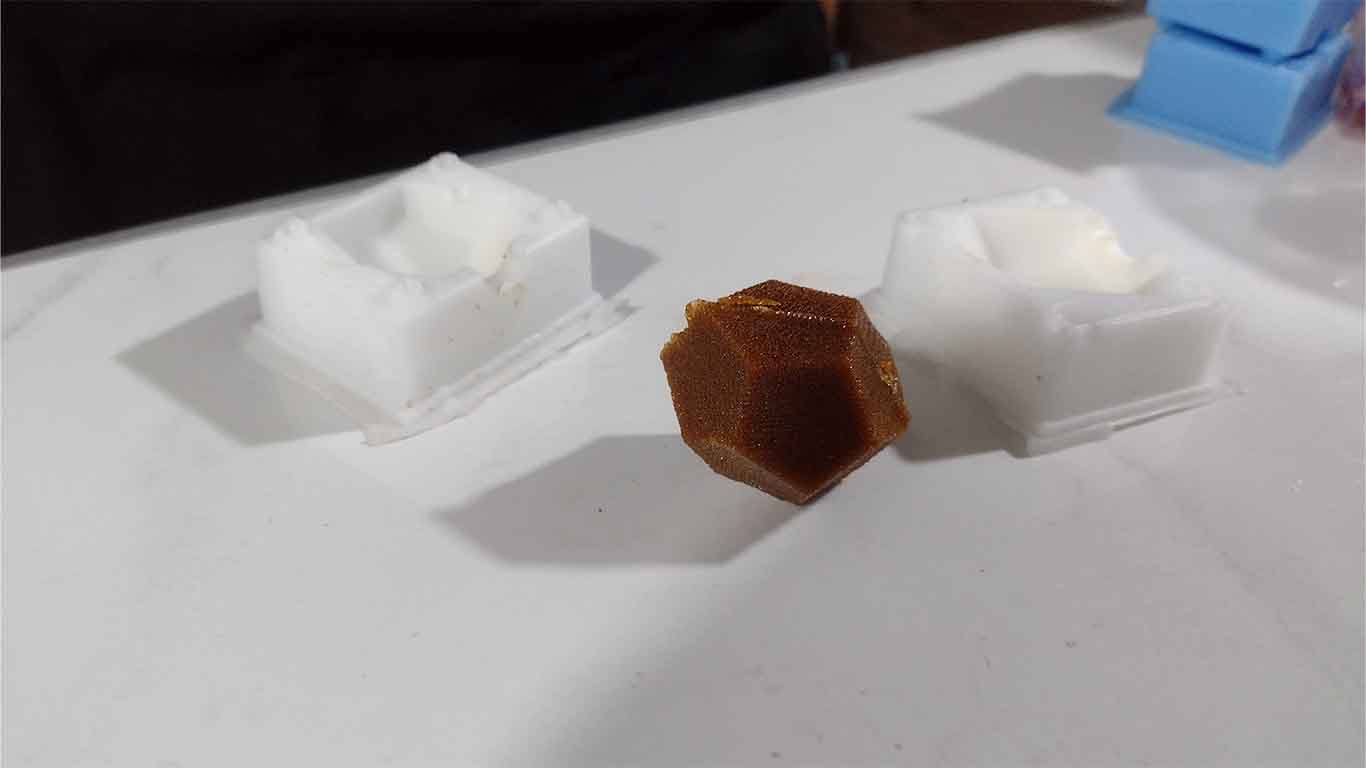
Here we can see that the burnt sugar could also obtain the shape of the dodecahedron and very detailed on its sides. It amazes me how these small details can be achieved.
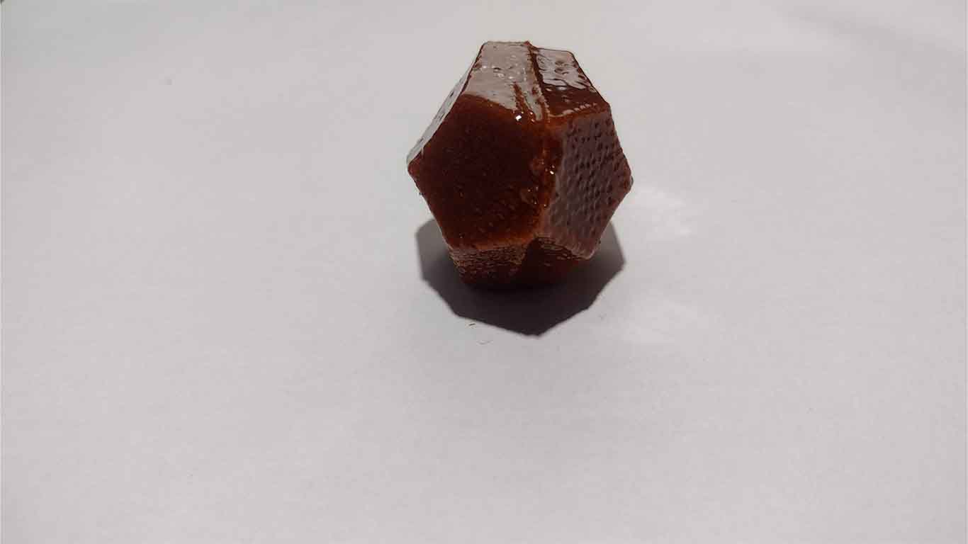
CANDLE
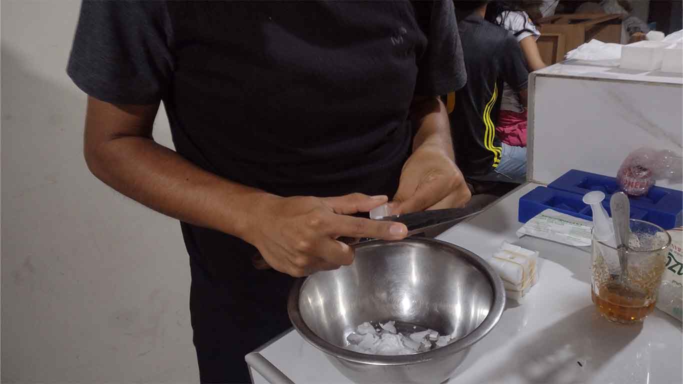
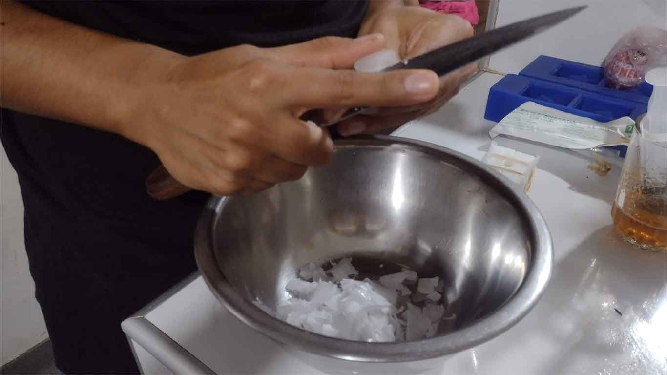
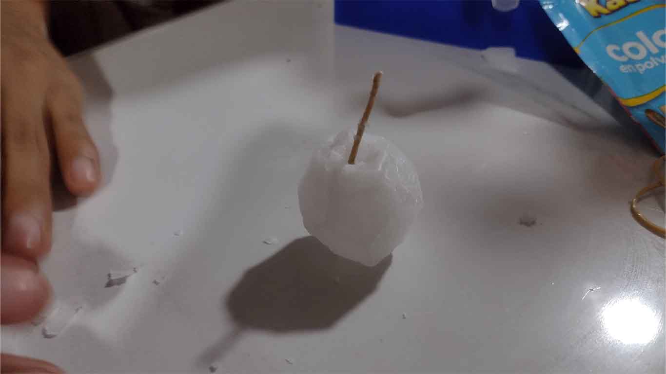
To make a candle, first I used a candle that was at home, I began to chop it with a knife until I had small lumps of wax. Here are some photographs of the first step.
Then, similar to the chocolate process, we melt the candle with a BAÑO MARIA until it becomes liquid and from there, we begin to pour it into our mold. We have to be careful because heat can affect our skin.
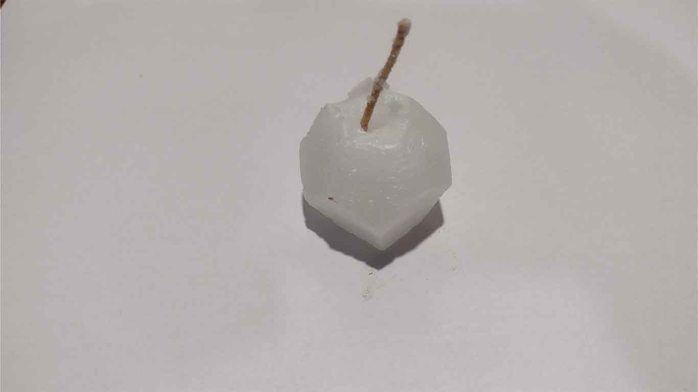
Since the wax dries quickly and does not take more than 10 minutes, the result is quick. Here are some screenshots of the result where the shape of the dodecahedron is not as detailed.
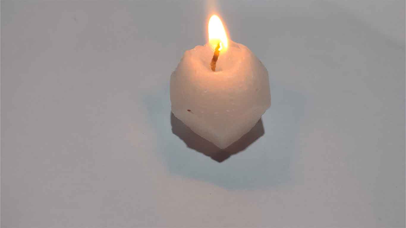
Here is a final photo of the lit dodecahedron candle.
SOAP
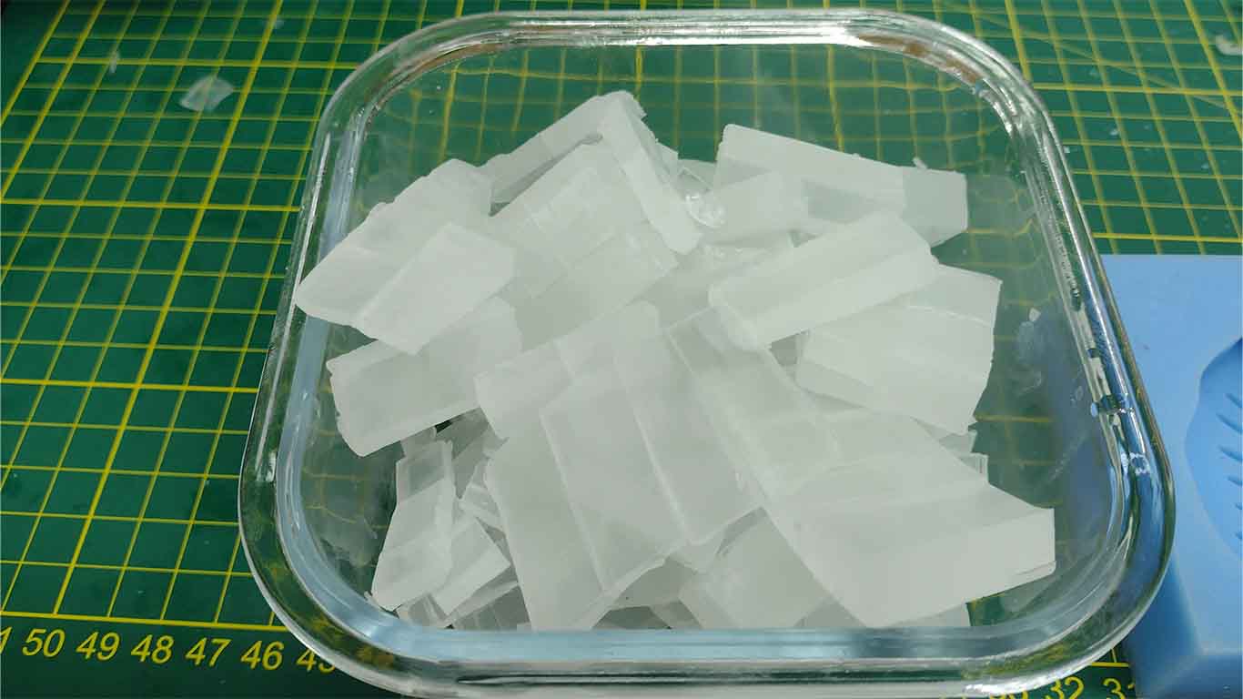
To make soap, we follow the same chololate or candle technique. Where we chop the pre-produced soap into small parts. Then, we can place it in a microwave for 30 seconds on high heat and it will melt or also do it in a BAÑO MARIA to turn it into liquid.
In my case we used the microwave and put FILL as a lid so that it can melt faster. Here is a screenshot of the moment where I am pouring the liquid soap into my mold. Thanks to Silvana for sharing some of the prepared soap with me and to Jose Alberto for the support.
Here is a screenshot where we see that the soap liquid reached the limit of my mold.
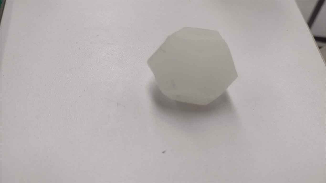
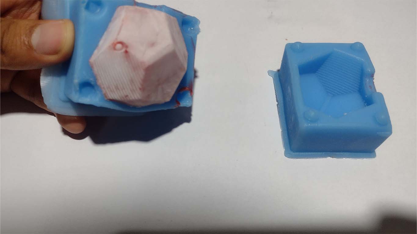
After approximately 30 minutes I could see that the soap had already become solid, so when it came time to unmold I was able to obtain the following result.
The soap was also able to obtain the shape of the dodecahedron, but not as detailed, it had some holes that, due to the delay in pouring, dried quickly, but it did obtain the shape.
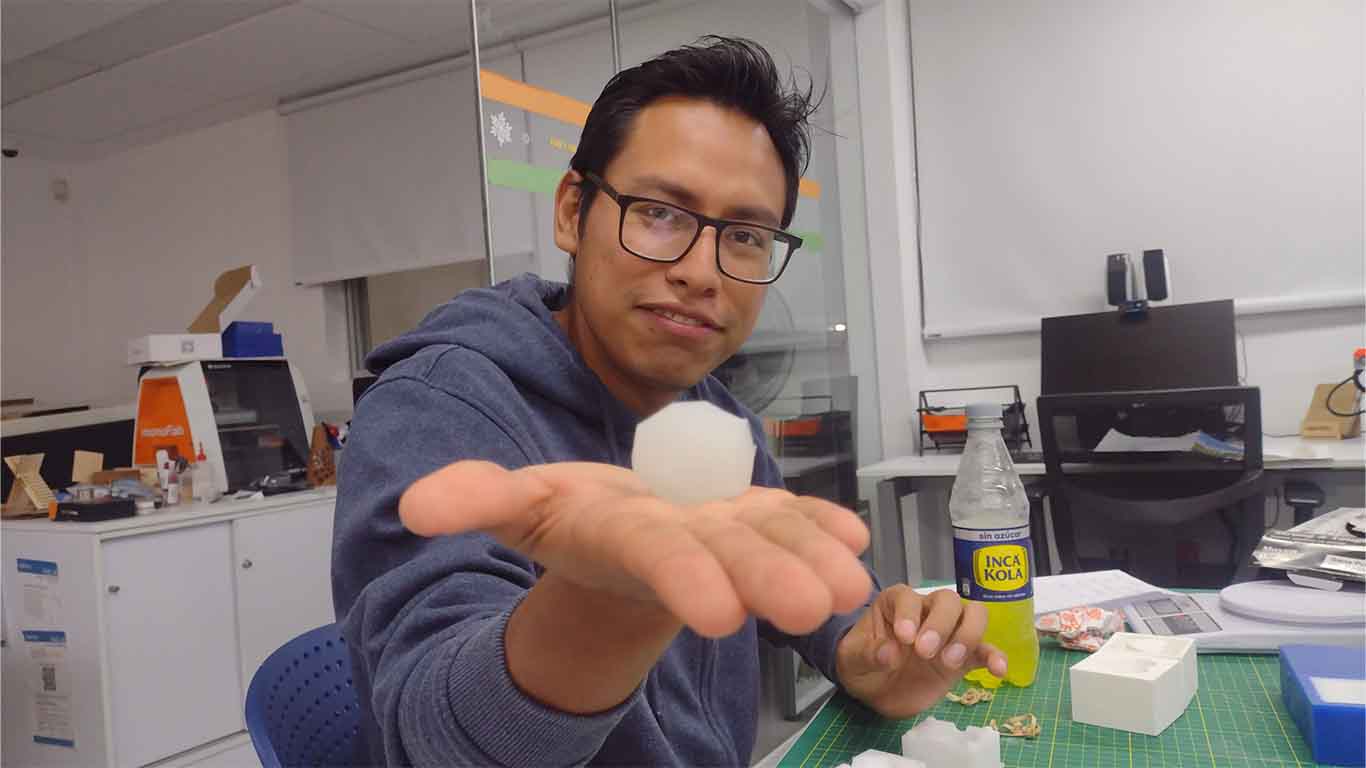
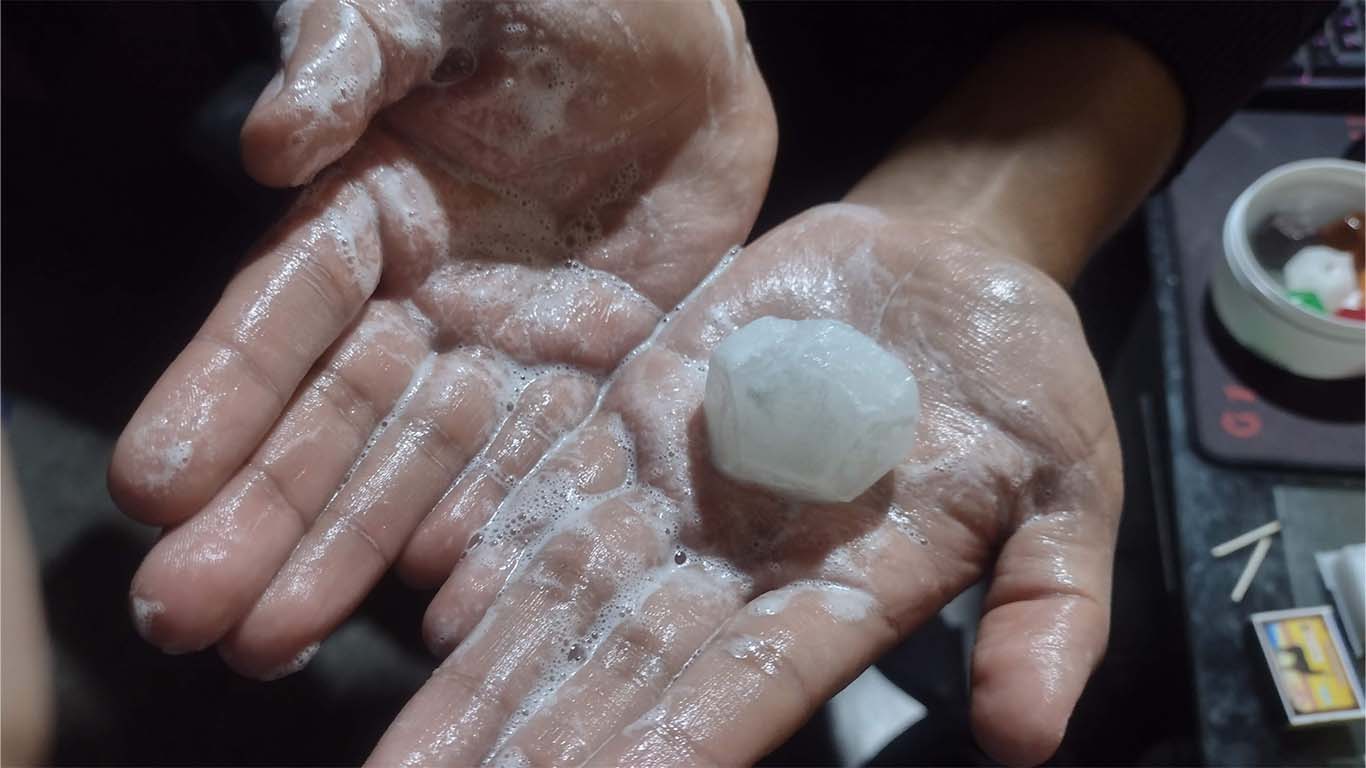
Finally, here is a test of washing my hand with my dodecahedron-shaped soap.
GELATINS
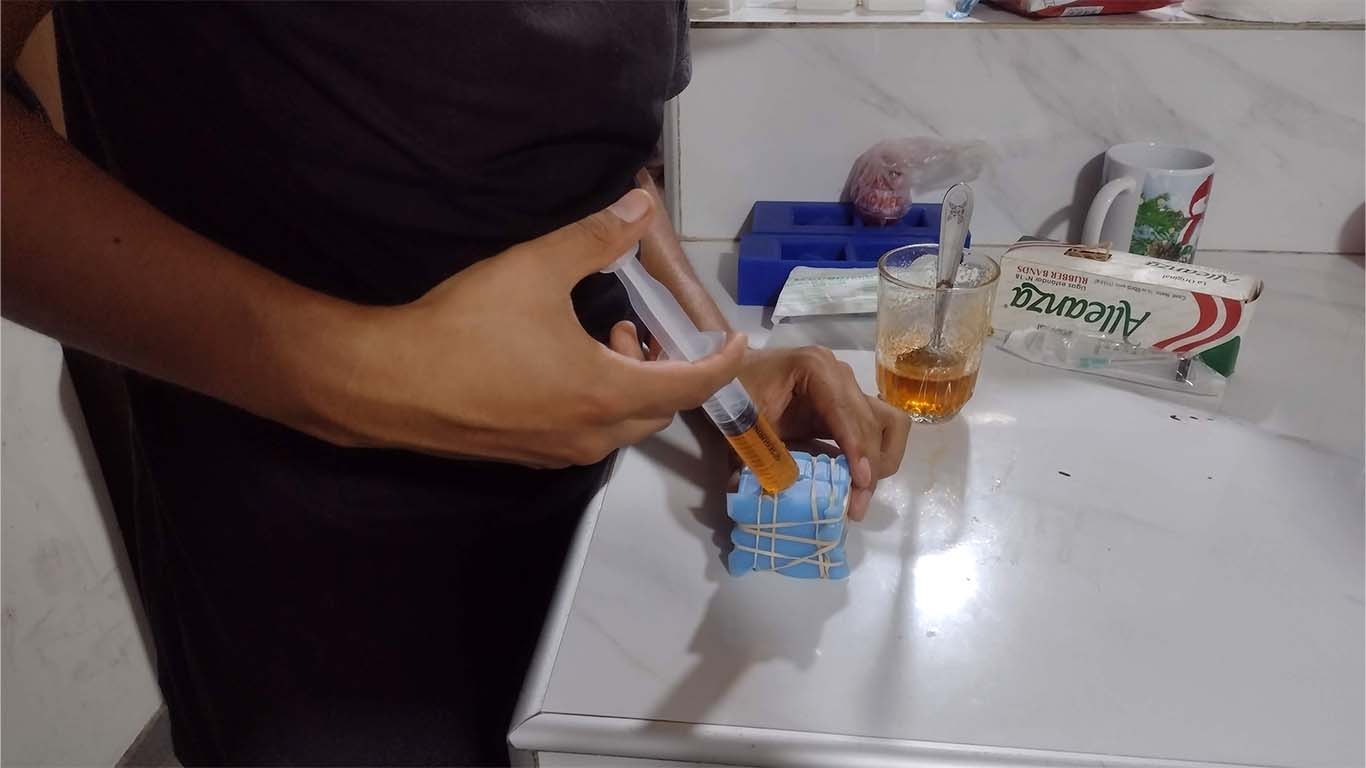
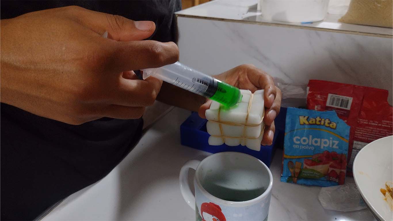
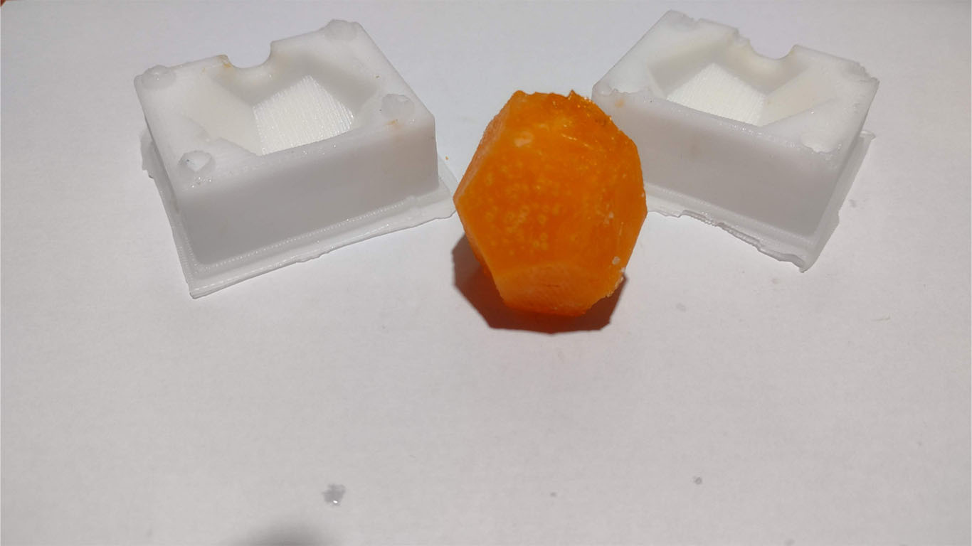
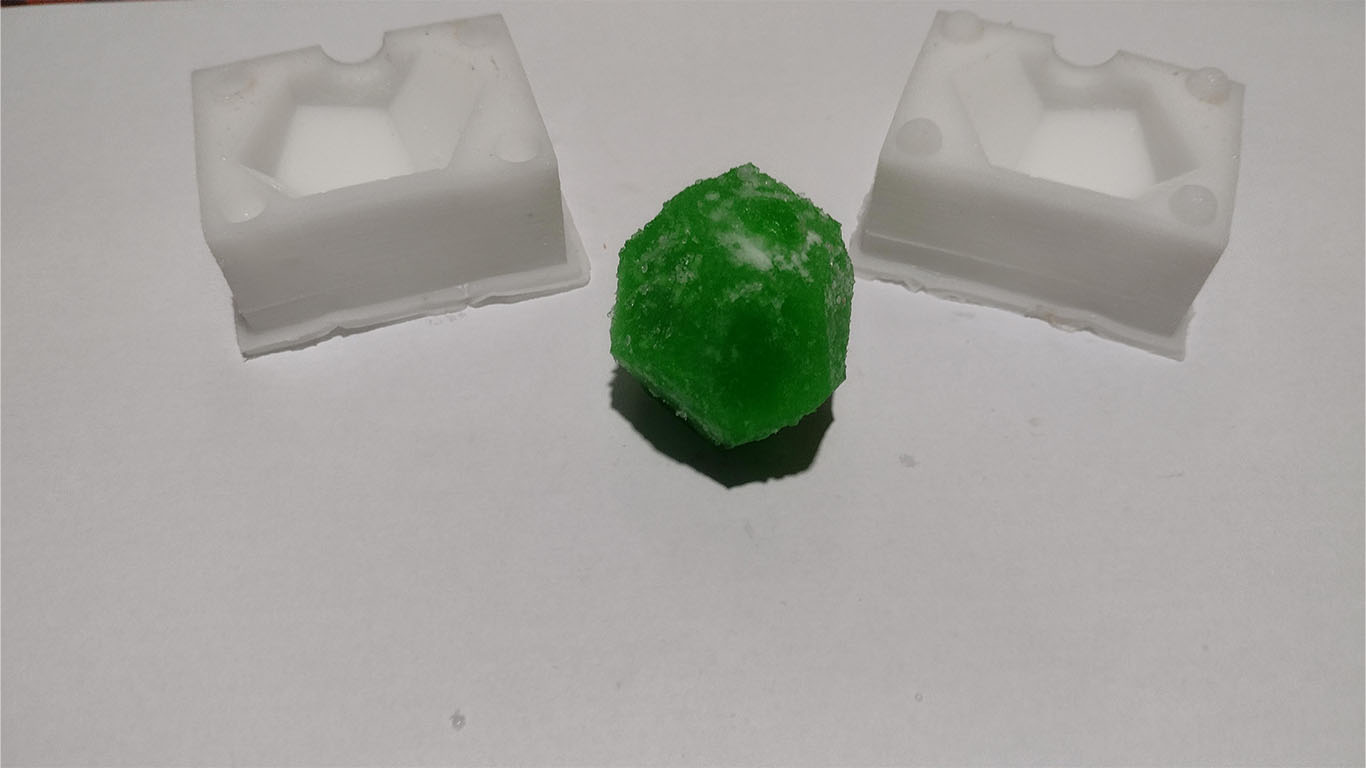
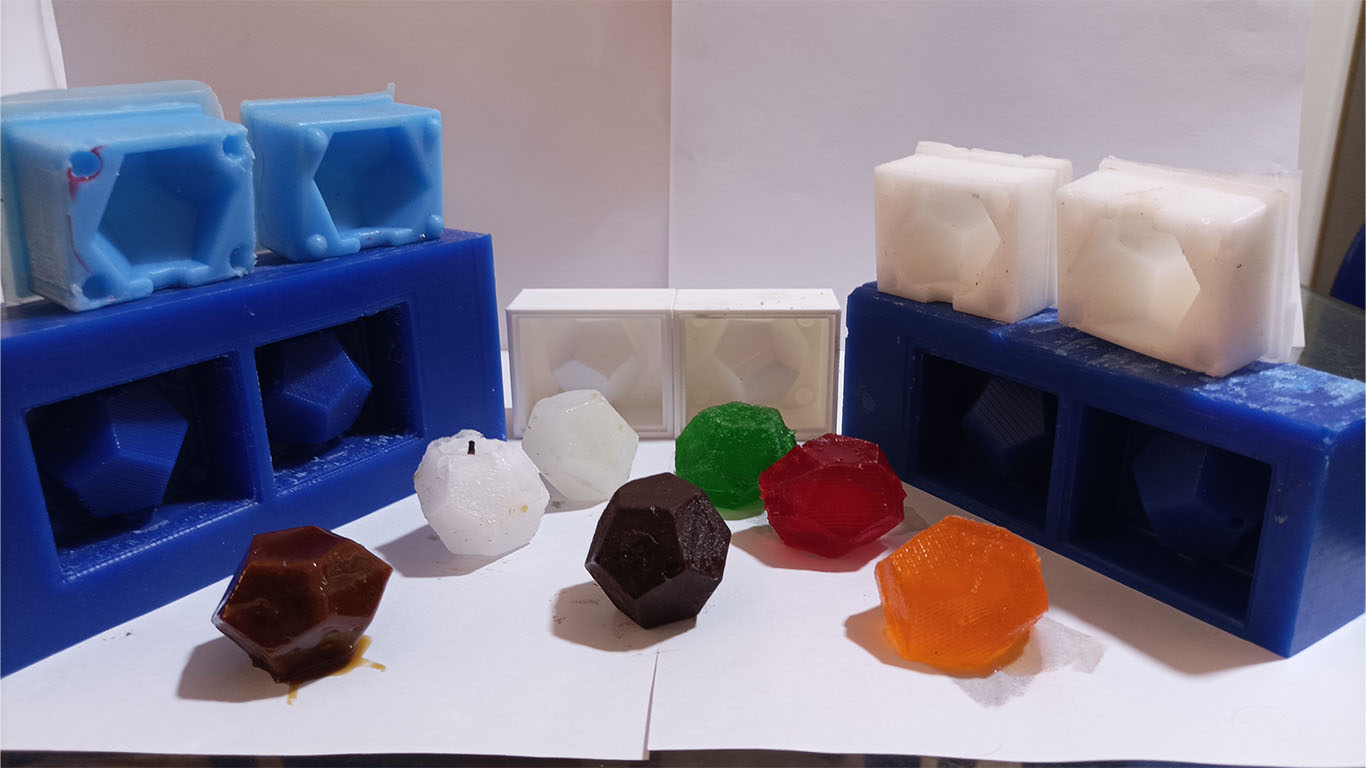
Some colleagues recommended that I can use gelatin for the following assignment. I was encouraged and performed with 3-color jellies, red, orange and green. Here I show you the process.
First, we pour a portion of gelatin of any color into a container of hot water. In my case, since my mold is not that big, I used a glass with the proportion mentioned by the gelatin brand.
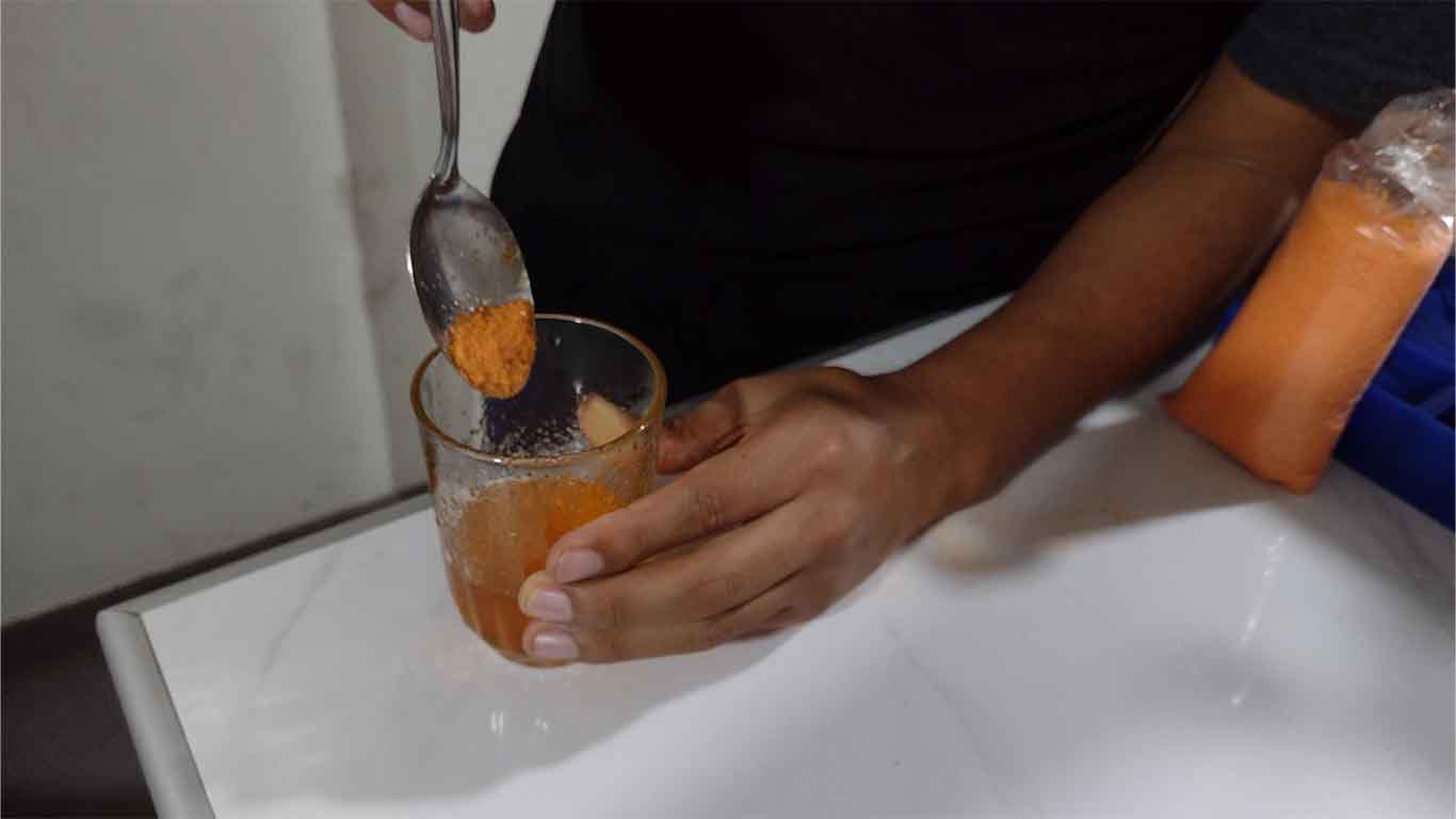
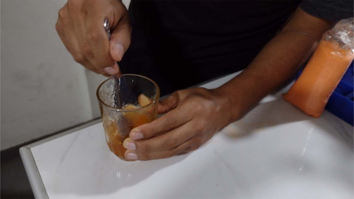
After mixing and moving until we had no solid gelatin, with the help of a syringe I poured the mentioned colors into each mold so that the entire mold was filled and also to prevent leakage. Finally we put the molds in the refrigerator.
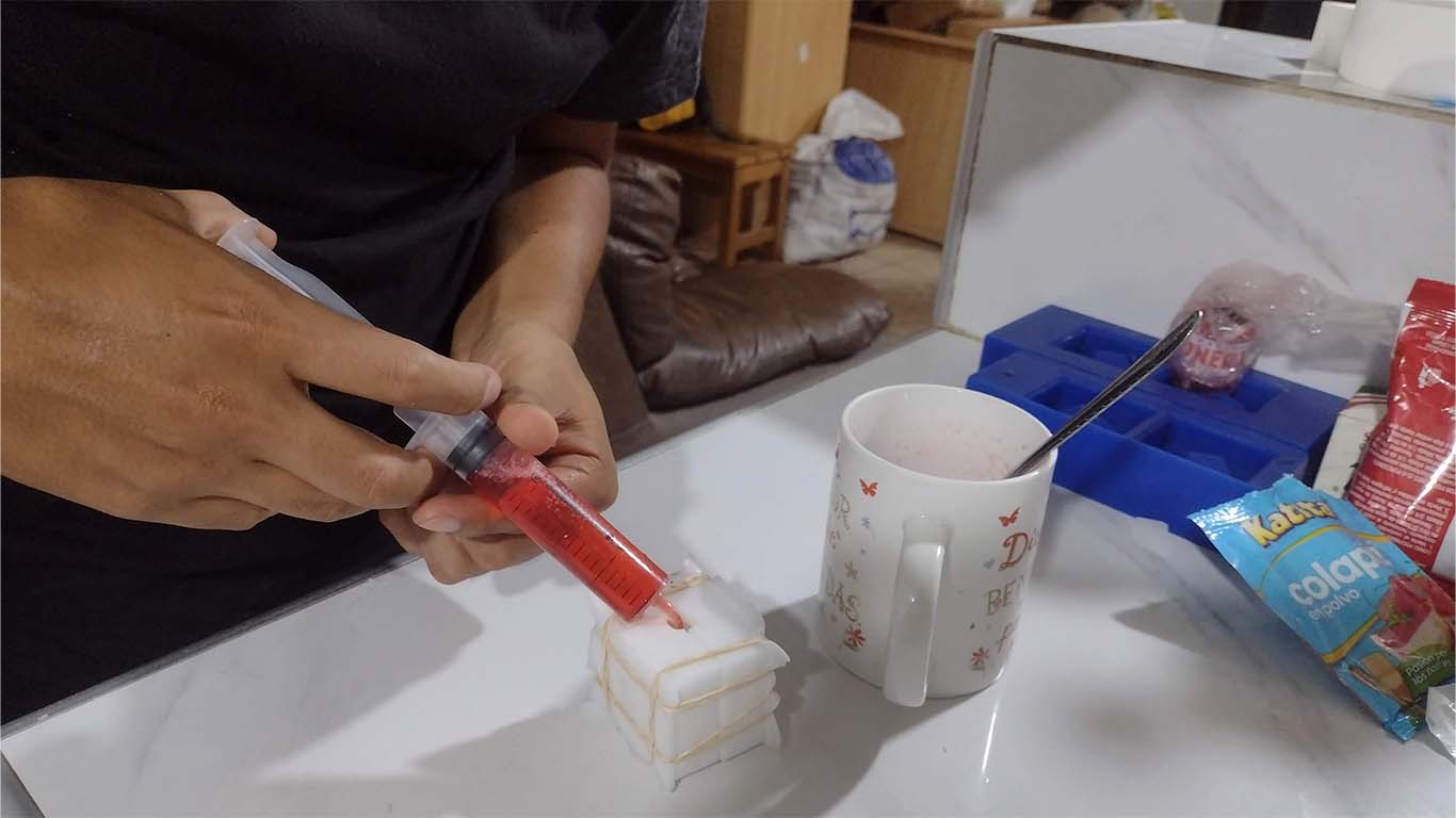
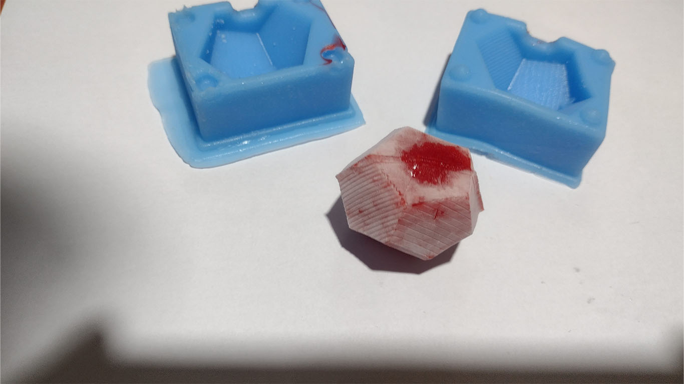
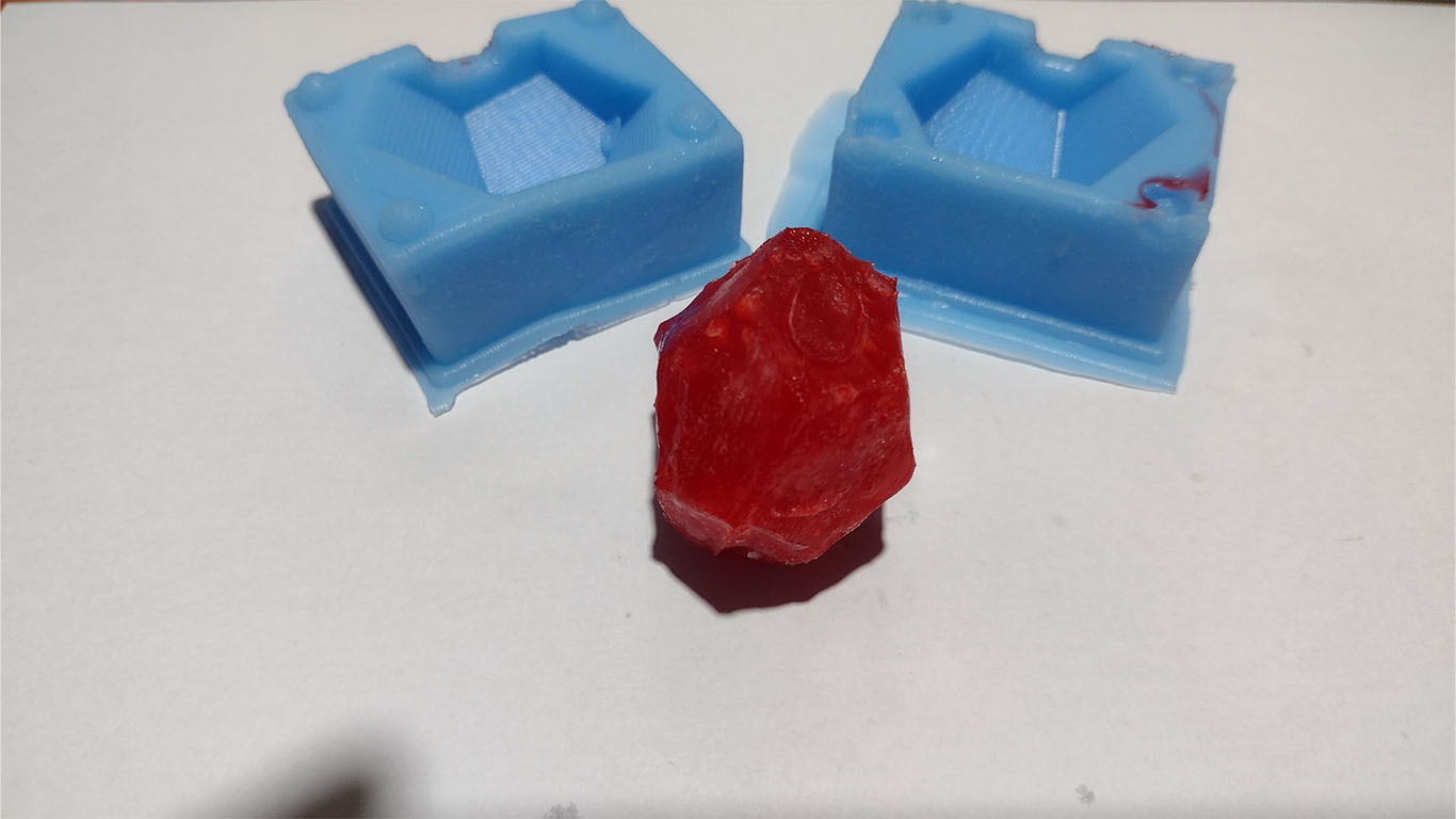
After a few minutes, which were approximately 30 minutes, I took the molds out of the refrigerator because I wanted to know if it was going to work. What I did was wrong because I had to wait longer because here are the results. They didn't freeze very well and broke when it was time to open the molds. Here is a photograph of the result, the red gelatin had dried faster but it still broke.
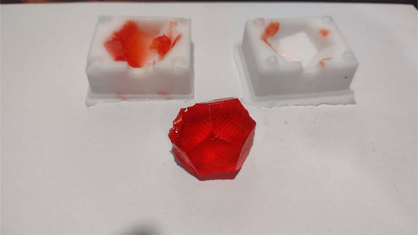
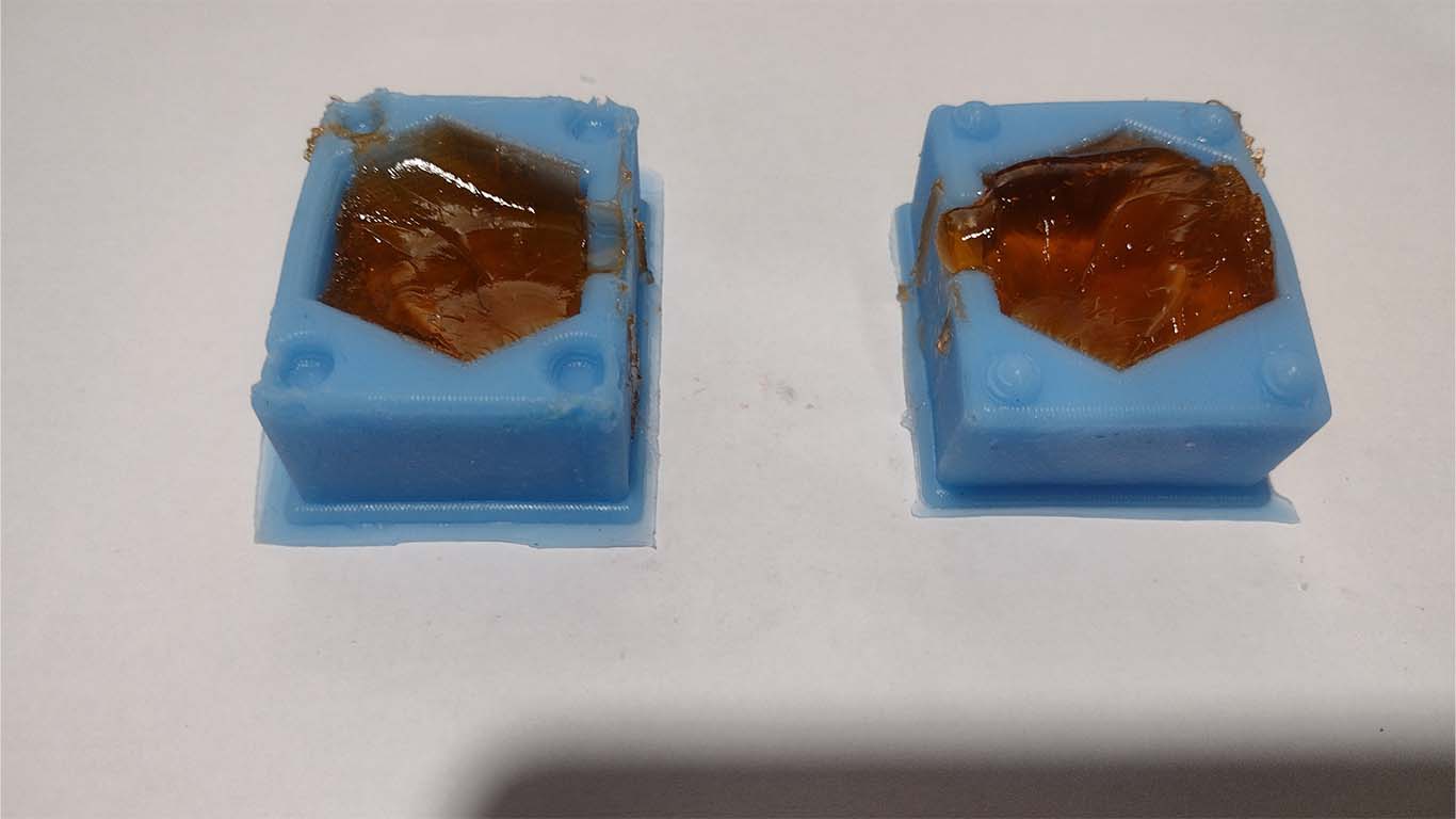
For my second test, I waited more hours to see if the jellies froze better and had greater consistency compared to the first test. Here is the result of my 2nd test with jellies.
I could see that by leaving it in the refrigerator longer, a small layer of ice appeared around each gelatin. I had to clean it to see the result.
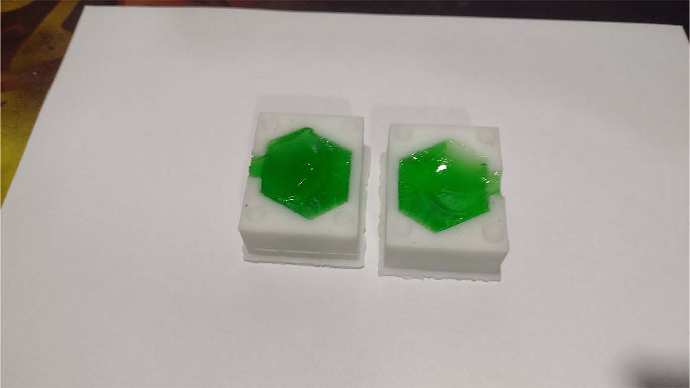
After cleaning it and removing the excess ice that had been generated around each gelatin, I could see the result and yes, the gelatin casting has the shape of my mold, in some of them it is not so clear but it was possible to obtain the 3 gelatin colors. Here are the photographs of each of them.
CONCLUSIONS
This week's assignment has been a challenge for me because I learned something new that I didn't know about: molds. After the inconveniences I had during the week with the supplies, we once again moved forward with achieving the assignment. I would have liked to achieve a better finish on the machine molds, I believe that better results can be obtained but I did not achieve it. On the other hand, I liked the way in which you work with molds, the characteristics and configurations that we must take into account. On the other hand, it is interesting the large number of silicones that we can get and that each of them has a suitable function for objects or foods. The work was very interesting, I learned and was very scared but I hope to continue learning more about molds and achieving a "perfect" mold with a machine.
REVIEW OF THE CLASS
During the review of this class I volunteered in the minute 1:27:10
Clic here to 20240424 review from Academany on Vimeo.
FILES
Here you can download all the files that I have made for the following assignment: