This week's assignment was:
- Probe an input device's analog levels and digital signals
- Measure something: add a sensor to a microcontroller board that you have designed and read it
ORGANIZATION
Here I show how I organized myself for this week.
| Wednesday 10th: | Fab Academy classes, organization for the week and review of all the input we have in FAB LAB UCSUR |
|---|---|
| Thursday 11th: | INPUT DEVICES class review and feedback from instructors. |
| Friday 12th: | Advance with the individual order and advance programming with some inputs. |
| Saturday 13th: | Enter OPEN GLOBAL TIME, learn more about the assignment and complete the group assignment. |
| Sunday: 14th: | Carry out documentation of everything developed. |
| Monday 15th: | Review and correction of documentation. Update and changes for last commit. |
| Tuesday 16th: | Documentation and last commit of the week. |
GROUP ASSIGNMENT
Here I leave the link to go to the group assignments page.
Clic here to visit the WEEK 11 GROUP ASSIGNMENT PAGE
PROBE AN INPUT DEVICE'S ANALOG LEVEL AND DIGITAL SIGNALS
TIME OF FLIGHT ANALOG LEVEL
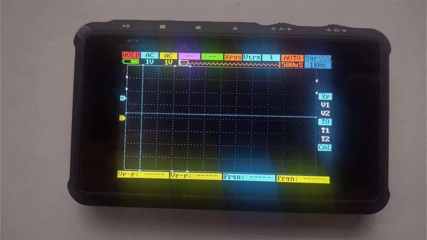
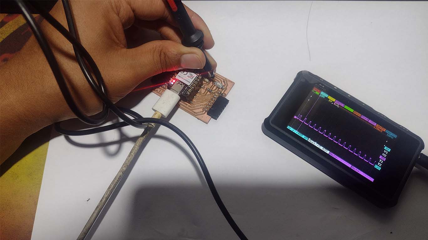
For the group assignment, we met with my colleagues from FAB LAB PERÚ and we will carry out the measurements of the analog level and 2-input digital signal that we chose. First we will work with the Time of Flight Distance to see the analog level behavior and then we will try with a switch that turns on an LED as a digital signal. The tool we will use is the DS213 oscilloscope that we have at the FAB LAB UCSUR.
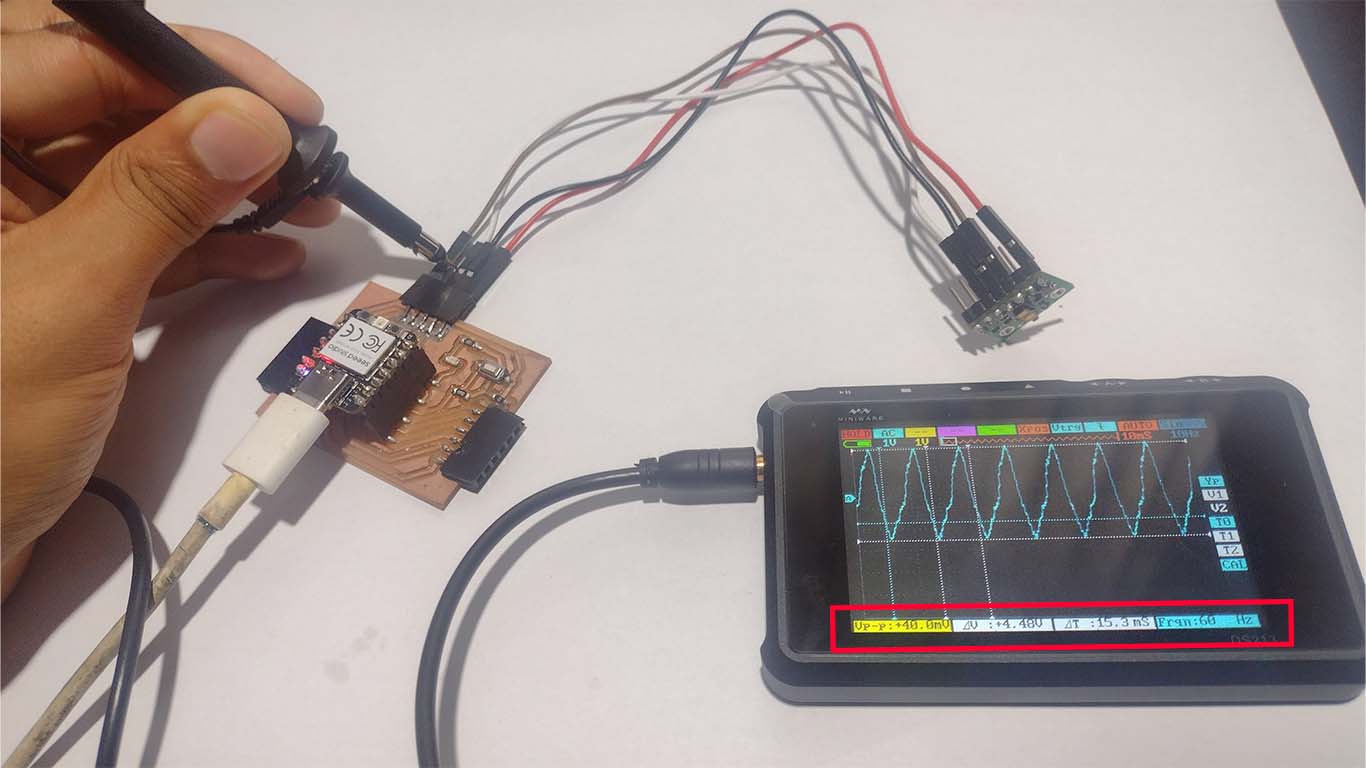
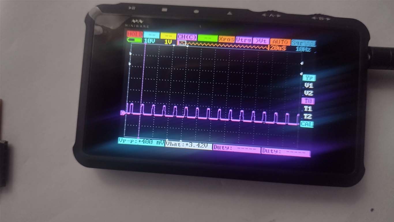
In the first test we perform an analysis in milliseconds of the frequency, where we begin to analyze in AUTO with 10 mS. Where we can see in the photograph that the frequency difference between the highest level and the lowest level is 15.3 mS. In addition, we analyze the voltage and we can see that between one wave and another there is 4.48V that passes, we can see this at the bottom of the oscilloscope.
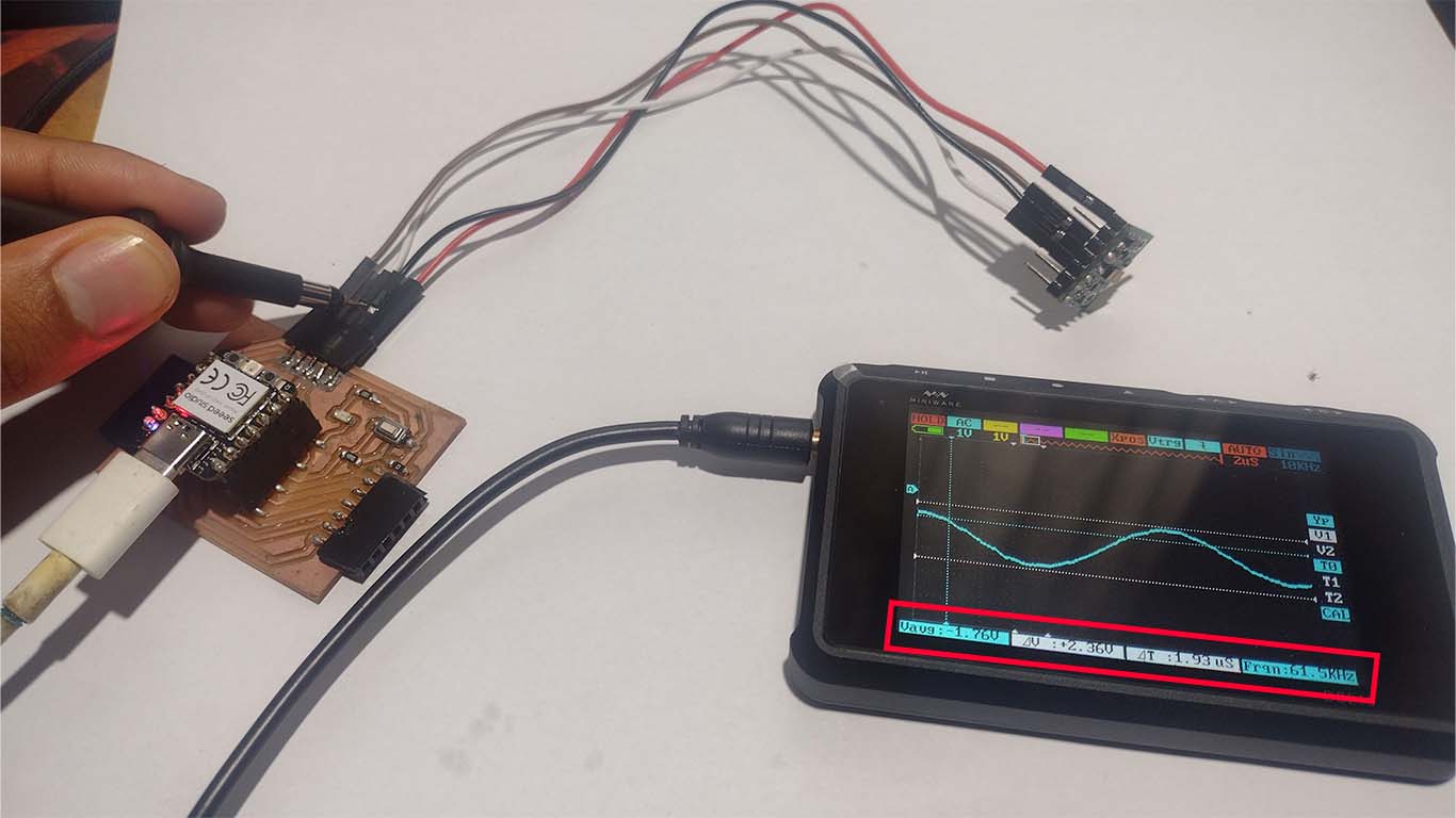
For the second test, we modify the time level to 2uS as can be seen in the photograph and we can see that the difference in the frequency of the wave is 1.93 uS between the highest level it reaches and the lowest level. This is when we are making contact with the SCL PIN of the sensor.
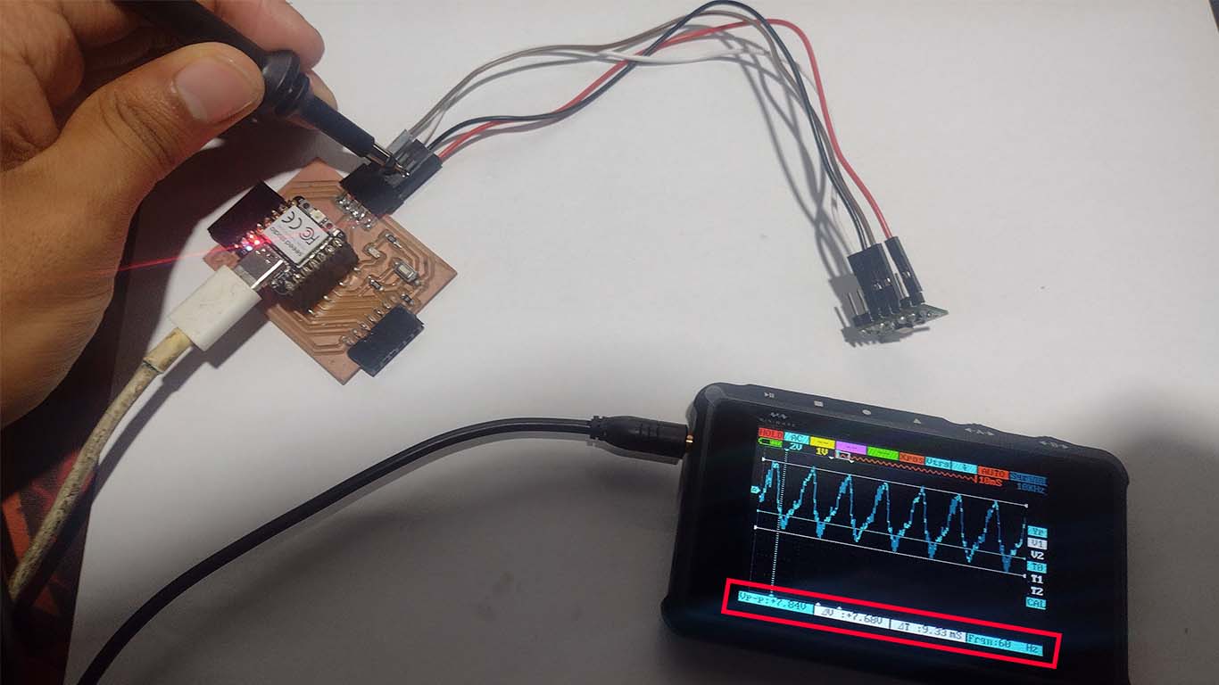
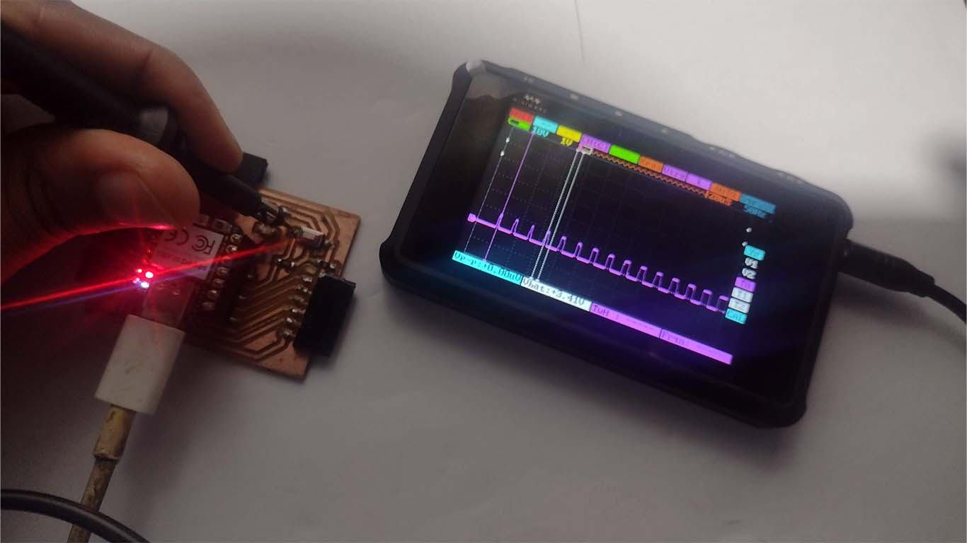
Then, by switching to the SCL PIN, we can see that the oscilloscope presents other data. Where we can see that the wave changes and the frequency has a difference of 9.33 mS between the highest part of the wave and the lowest part of the wave.
Here is a video of how we measure the analog level of the time of flight distance sensor when it is working. Here we can see the difference when we make contact with one of the sensor information pins.
DIGITAL SIGNALS - SWITCH
To obtain the digital signals, we wanted to practice with an LED and a SWITCH that makes the LED turn on when pressed. Here we can see the process of the digital signals that the oscilloscope reads to understand the operation of these components.
First we programmed in ARDUINO IDE so that when we touch the switch, the LED can turn on and after doing this step, we made contact with CHANNEL C of the OSCILLOSCOPE (digital channel) with the SWITCH and we could see the digital signal that the board is sending for it. . Here is a photograph of the moment.
Then, we tried to measure the frequency they had between digital signals 0, that is, the lower part. Here in the photograph we can see the white lines that we can use on an oscilloscope to obtain the exact data.
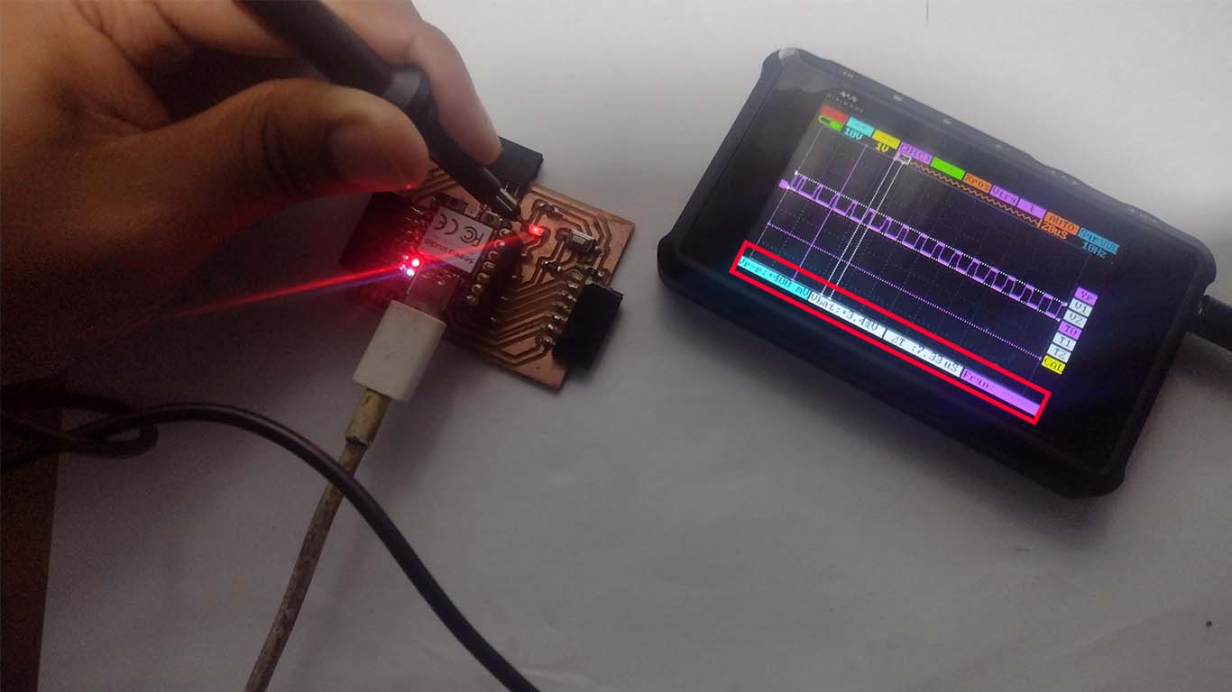
Finally, we also made contact on the LED while it was on and we were able to obtain the data we need thanks to the oscilloscope. In time, we have approximately 7.33 uS of time between signal and the voltages vary from 0 to 3.41V. Here we can understand how digital signals work and see that when we turn on an LED, for example, the digital power signal "1" is activated and then drops to "0".
Here we can see a video of what the digital signals sent by the SWITCH look like and the LED reads them in order to turn on.
CONCLUSIONS
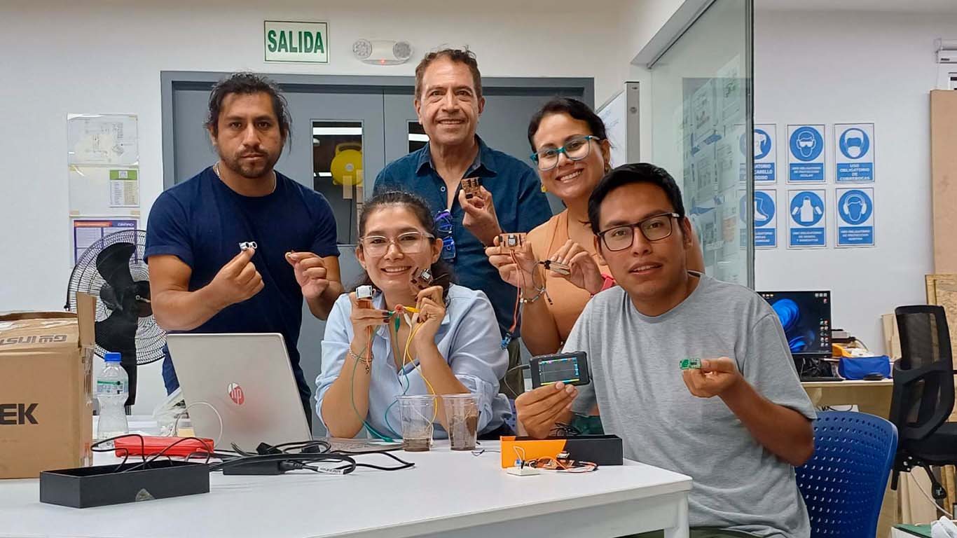
One more week of teaching and a lot of practice to understand a very complex world like electronics. This week I can conclude that I learned a lot about digital and analog signals. Now I understood the difference much more and we can see them in a "real" way on instruments like the oscilloscope. Finally, I can conclude that we must take into account that each INPUT has its characteristics and know if it is DIGITAL or ANALOG. From there, we can understand how it works, connect to the correct PINS of our microcontrollers to make better use of them and ensure they function better. Here is a group photo with my FAB LAB colleagues, each with the inputs seen and reviewed for the week.
SUPPORT AND FEEDBACK
FEEDBACK
The day after the INPUT DEVICES class, we met with our instructors to give us feedback on the class. They will explain to us how the inputs work, what they are asking us for in the orders and to resolve our doubts.
GLOBAL OPEN TIME SUPPORT
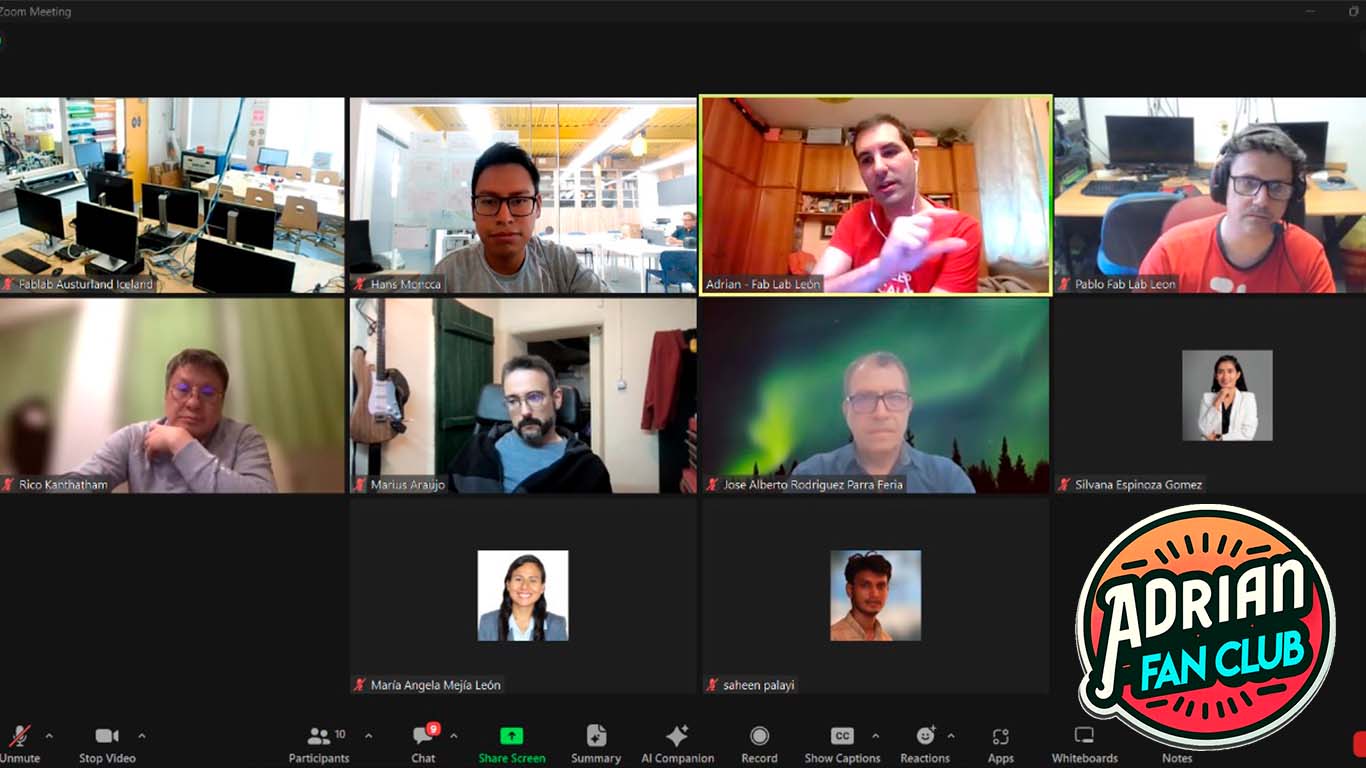
On Saturday as a group we joined the OPEN GLOBAL TIME and as always Adrian, Rico and other colleagues supported us to solve our doubts for the week. The truth is that these meetings are very interesting because they help us to get rid of the doubts that each week generates. Thank you very much for another week of teachings teachers, you are very professional.
INDIVIDUAL ASSIGNMENT
MEASURING SOMETHING...
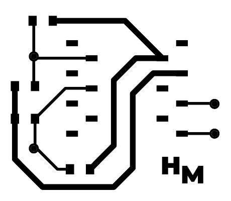
HM DEVELOPMENT BOARD AGAIN
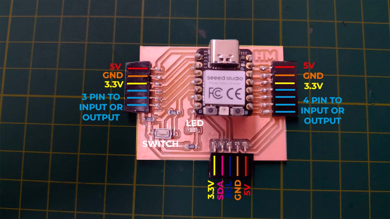
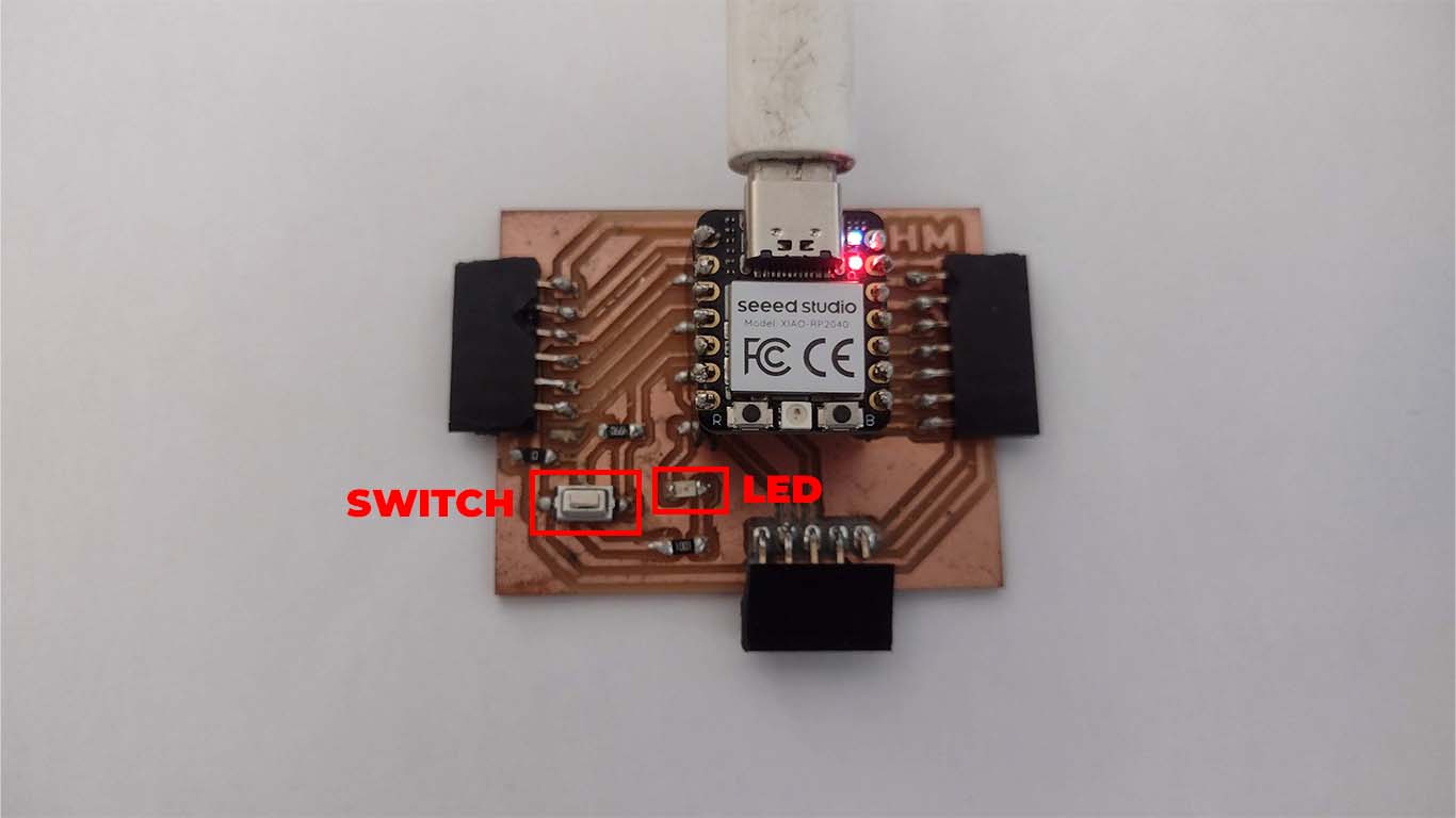
For the next assignment, I am going to use my development board that I made during the OUTPUTS DEVICE week. Here I leave a screenshot of how I distributed the pines and link
INPUTS DEVICE
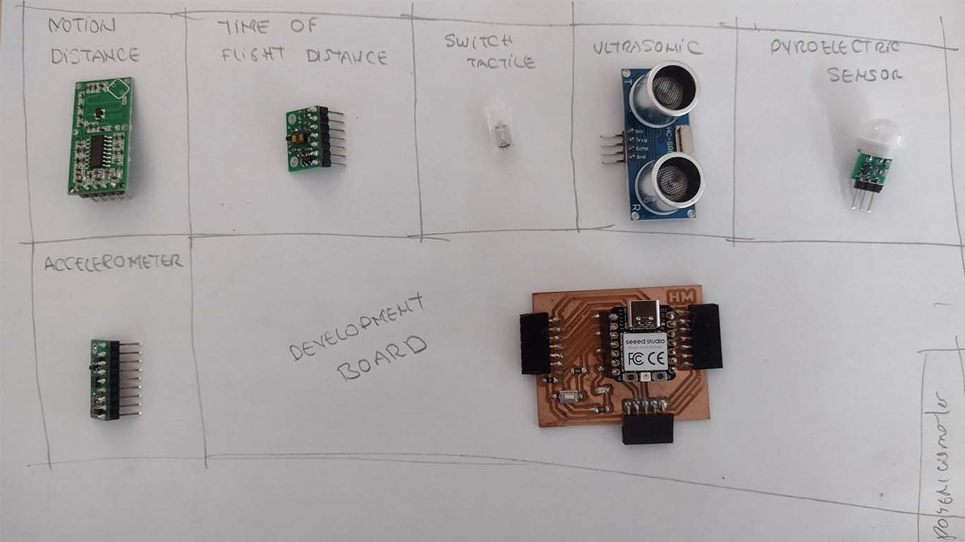
Before starting the assignment, I took an inventory in the FAB LAB UCSUR to find all the inputs that I could use for this week. Here I leave a screenshot of a small organization of all the components I found. Finally, I wanted to start the assignment by taking the inputs that were most familiar to me and others that I am just getting to know this week.
SWITCH TACTILE
I started with the TACTILE SWITCH, which is an input that I placed on my development board upon recommendation in OPEN GLOBAL TIME. Here is a sample of how I programmed it and how it works. When you press the button, the LED flashes 3 times each time you press the switch.
Here I leave the programming code so that when pressing the SWITCH (input) the LED (output) flashes 3 times each time we press it. Then a video of how it works
                                // Define the pins to be used
                                    const int pinLED = 0; // Pin where the LED is connected
                                    const int pinSwitch = 29; // Pin where the switch is connected

                                    void setup() {
                                    // Configure the LED pin as output
                                    pinMode(pinLED, OUTPUT);
                                    // Configure the switch pin as input with pull-up
                                    pinMode(pinSwitch, INPUT_PULLUP);
                                    }

                                    void loop() {
                                    // Read the state of the switch
                                    int switchState = digitalRead(pinSwitch);

                                    // If the switch is pressed (LOW state)
                                    if (switchState == LOW) {
                                        // Turn on the LED
                                        digitalWrite(pinLED, HIGH);
                                        // Perform three flashes
                                        for (int i = 0; i < 3; i++) {
                                        digitalWrite(pinLED, HIGH);
                                        delay(500); // Turn on the LED for 500 ms
                                        digitalWrite(pinLED, LOW);
                                        delay(500); // Turn off the LED for 500 ms
                                        }
                                        // Turn off the LED
                                        digitalWrite(pinLED, LOW);
                                        // Wait until the switch is released
                                        while (digitalRead(pinSwitch) == LOW) {}
                                    }
                                    }
PYROELECTRIC SENSOR
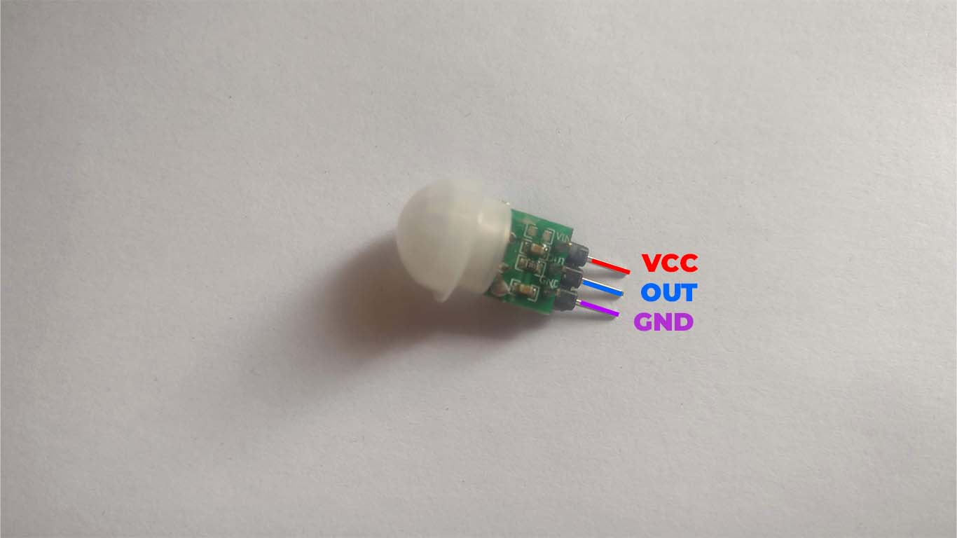
Now the input I used was a pyroelectric sensor, which is a device that detects changes in the infrared radiation emitted by nearby objects to activate an electrical response, commonly used in security and automation systems. Here is a photograph of the pins that it makes up for its operation.
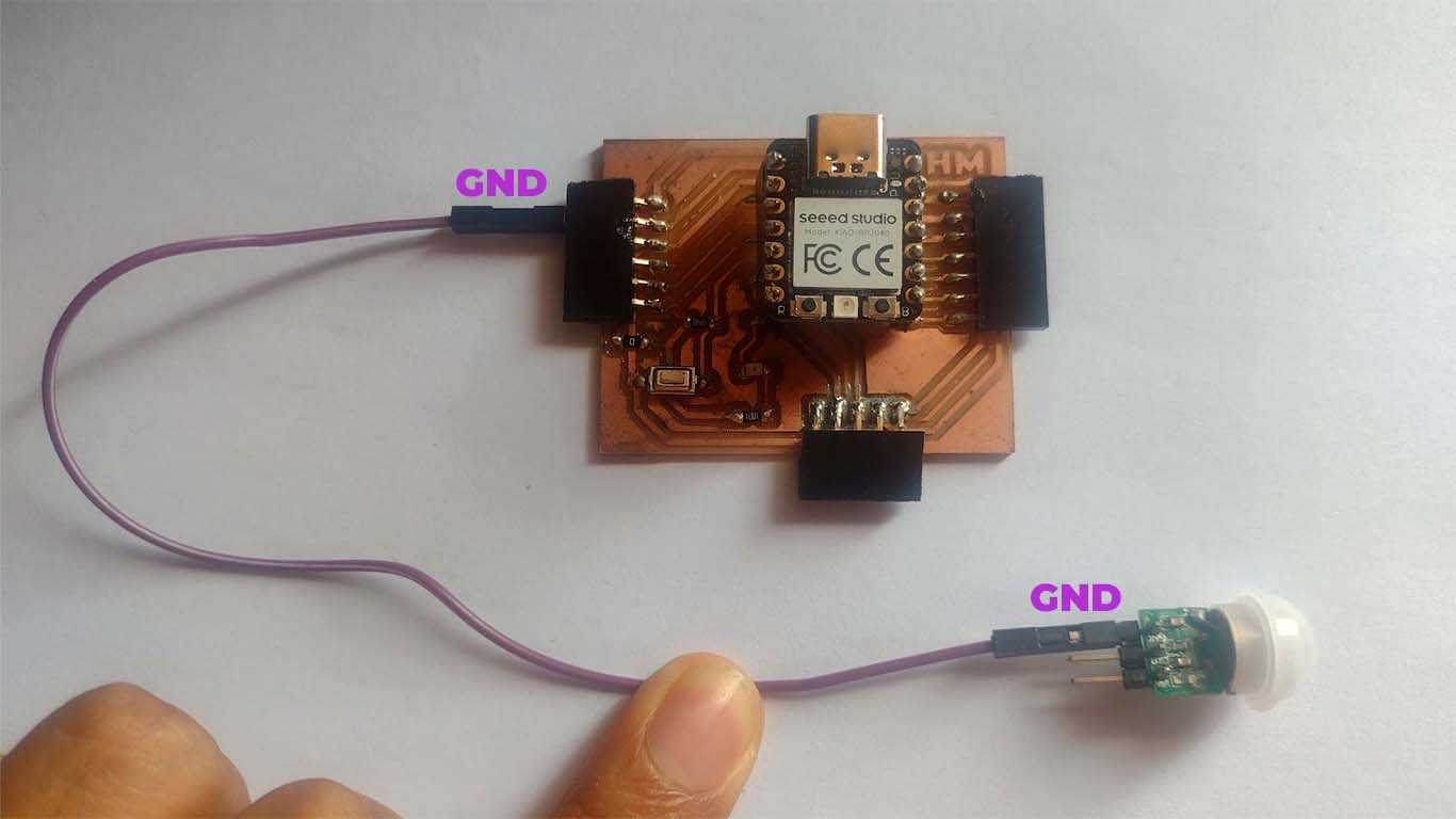
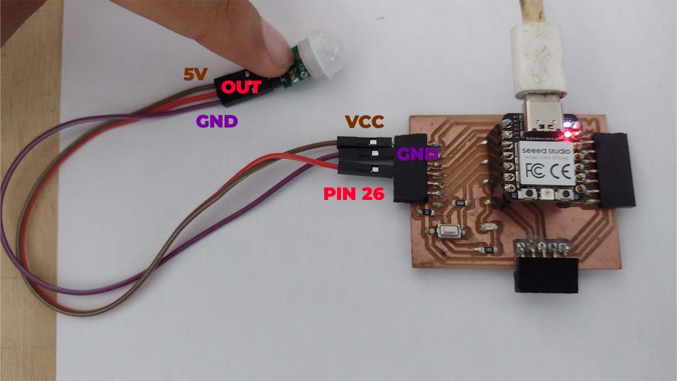
First we will connect the GND of the component to the GND of the development board. Here is a photograph of the connection.
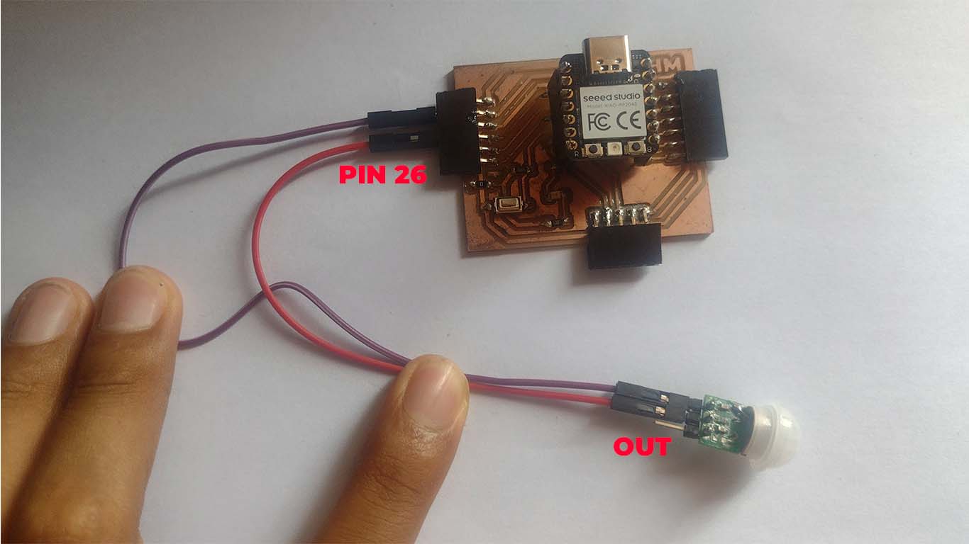
Then connect the OUT to the development board, in this case I will connect it to the PIN 26 connector of my XIAO RP2040.
Finally, we place the VCC of the pyroelectric sensor into the 5V connector of the XIAO RP2040.
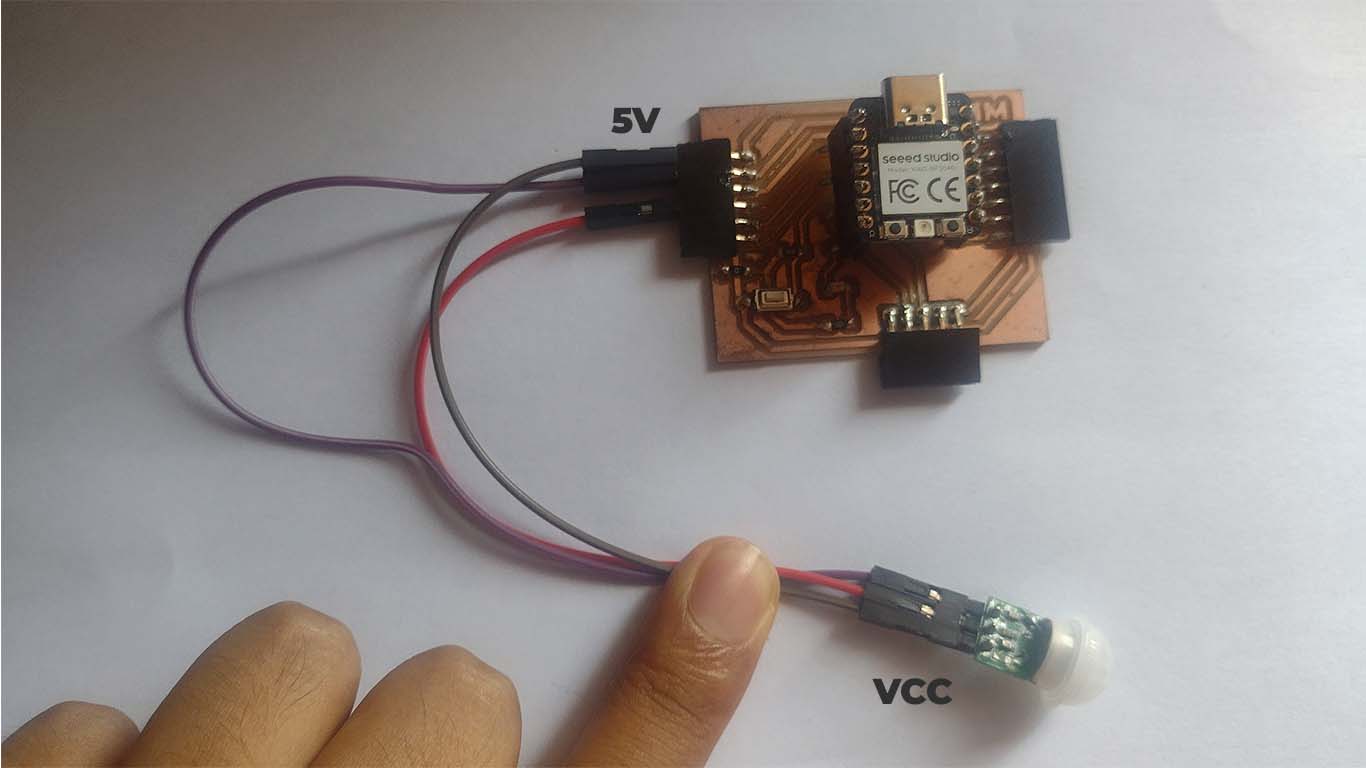
Here is a summary photograph of the connection I made to my development board.
For programming, I used the ARDUINO IDE, here is the code I used.
                                // Define the PIR sensor pin
                                const int pinPIR = 26;

                                void setup() {
                                // Start serial communication
                                Serial.begin(9600);
                                // Configure the PIR sensor pin as input
                                pinMode(pinPIR, INPUT);
                                }

                                void loop() {
                                // Read the state of the PIR sensor
                                int pirState = digitalRead(pinPIR);

                                // If motion is detected
                                if (pirState == HIGH) {
                                    // Print "movement" message on the serial port
                                    Serial.println("movement");
                                } else {
                                    // Print "off" message on the serial port
                                    Serial.println("off");
                                }

                                // Wait for a brief period before reading again
                                delay(1000);
                                }
Here is a sample video, where we see that the sensor sends a signal in SERIAL when it detects movement and OFF when it does not detect movement.
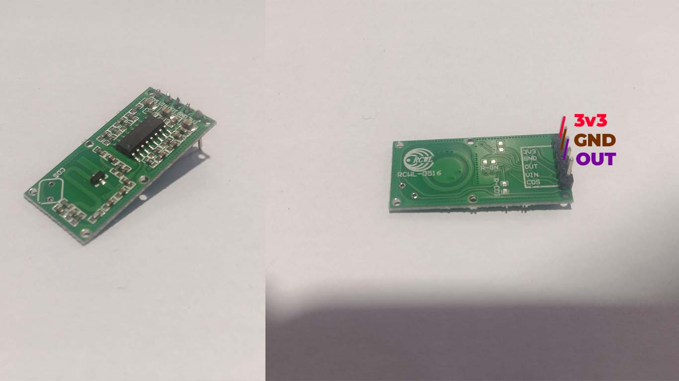
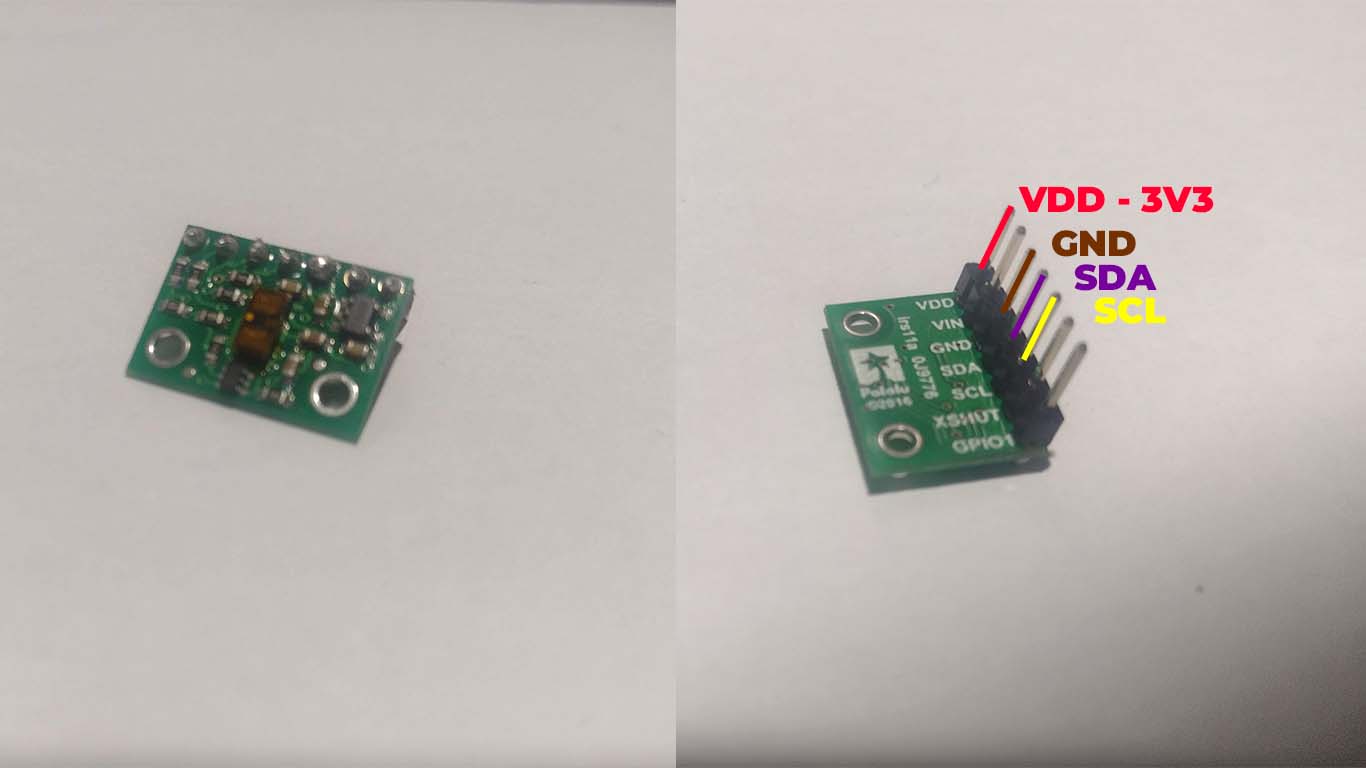
MOTION DISTANCE
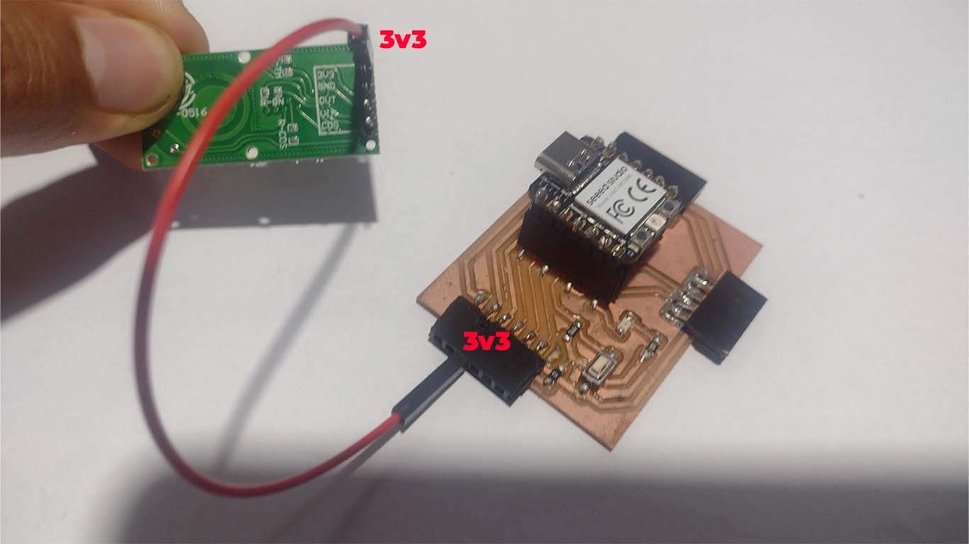
Now the input I made is the motion sensor, it is an electronic device designed to detect the presence or movement of objects in its environment. To collect information and connect it to the development board we only need 3 pins of the sensor, the 3V3 power supply, the GND and the OUT to achieve its operation and reading.
First we will connect 3V3 of the sensor to 3V3 of the development board. In this case I will use red cable for identification like the photograph.
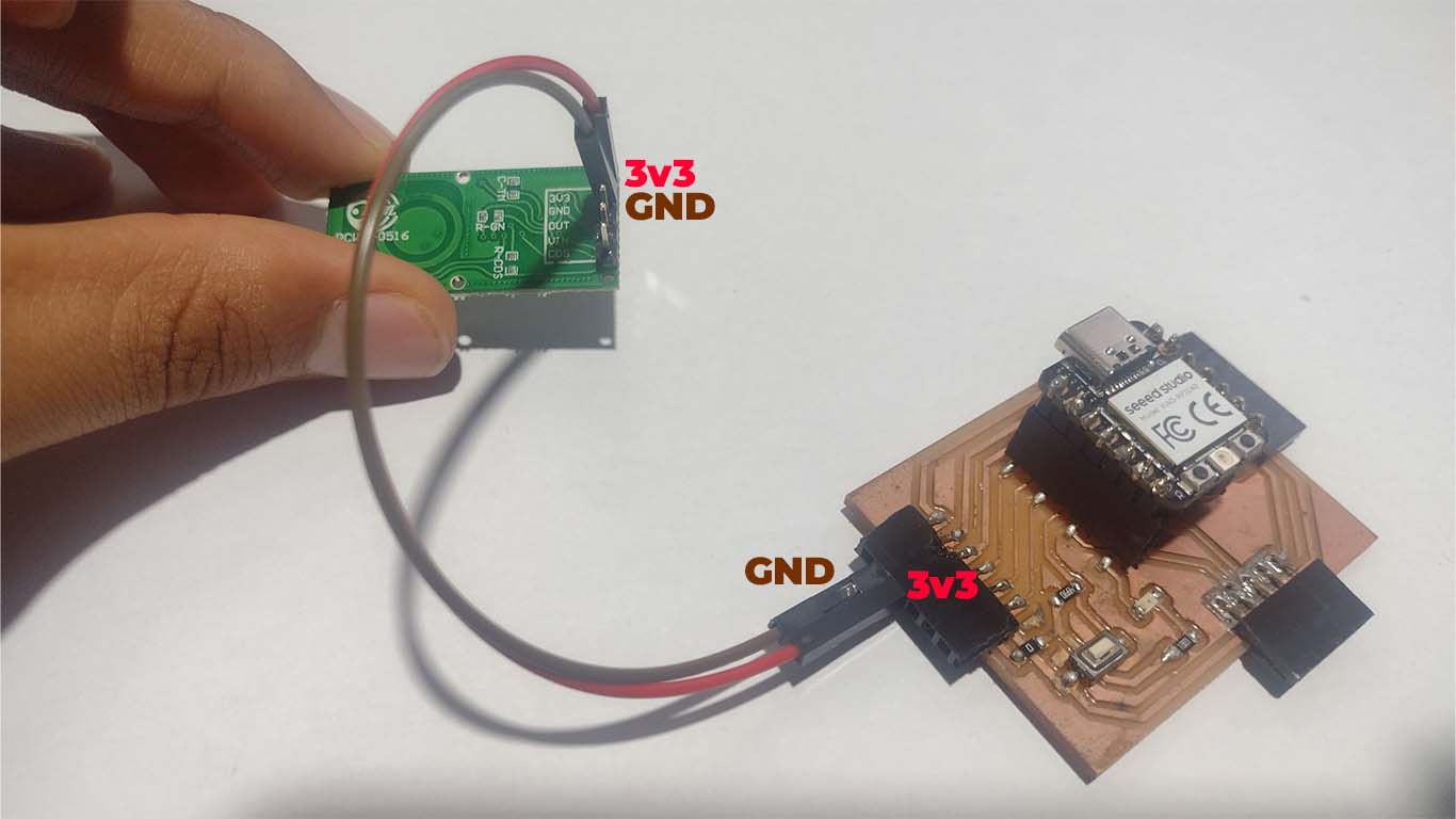
Then we will connect GND with the GND of our development board, in this case I used the brown cable to identify it as seen in the photograph.
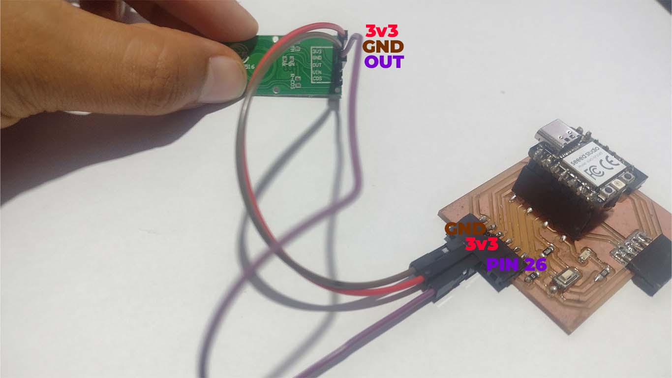
Finally, we will place the OUT pin of the sensor in the connector that has PIN 26 for this test. For this case I used the purple cable for identification.
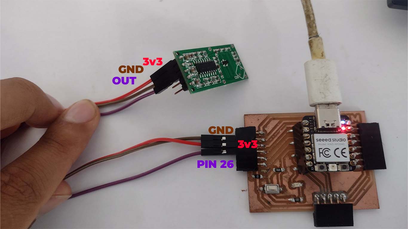
Here is a summary photograph of the connection I made of the sensor with my development board. Now we connect the XIAO RP2040 with our computer for programming.
For programming, I used the ARDUINO IDE, here is the code I used.
                                // Define the motion distance sensor pin
                                const int pinMotion = 26;

                                void setup() {
                                // Start serial communication
                                Serial.begin(9600);
                                // Configure the motion distance sensor pin as input
                                pinMode(pinMotion, INPUT);
                                }

                                void loop() {
                                // Read the state of the motion distance sensor
                                int motionState = digitalRead(pinMotion);

                                // If motion is detected
                                if (motionState == HIGH) {
                                    // Print "movement" message on the serial port
                                    Serial.println("movement");
                                } else {
                                    // Print "off" message on the serial port
                                    Serial.println("off");
                                }

                                // Wait for a brief period before reading again
                                delay(1000);
                                }
Here is a sample video, where we see that the sensor sends a signal in SERIAL when it detects MOVEMENT and OFF when it does not detect movement.
ULTRASONIC SENSOR
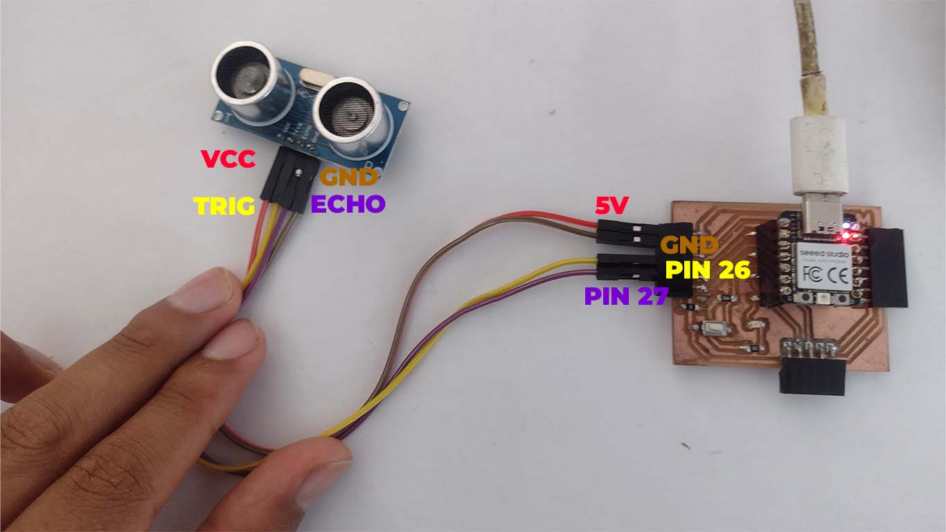
The next input that we are going to use is the ultrasonic sensor, it is a device that uses high-frequency sound waves to measure distances between the sensor and an object, commonly used in proximity detection and distance measurement systems.
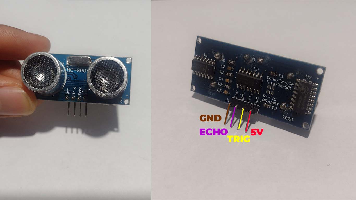
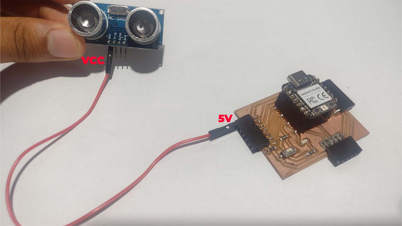
First we will connect the VCC pin of the sensor to the 5V pin of the development board, to identify it we will connect it with a red cable.
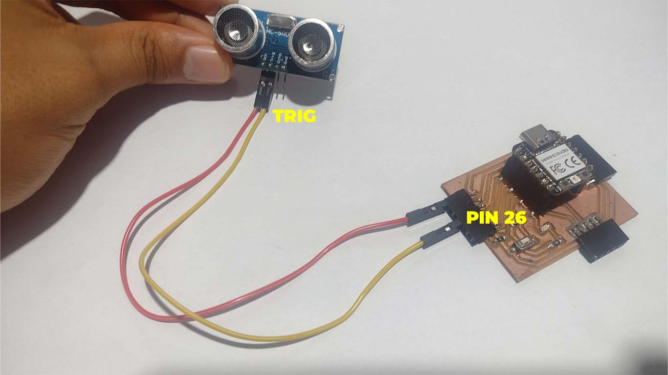
Then we will connect the TRIG PIN of the sensor with one of the pins on the development board. For this we will connect it with PIN 26 of the XIAO RP2040.
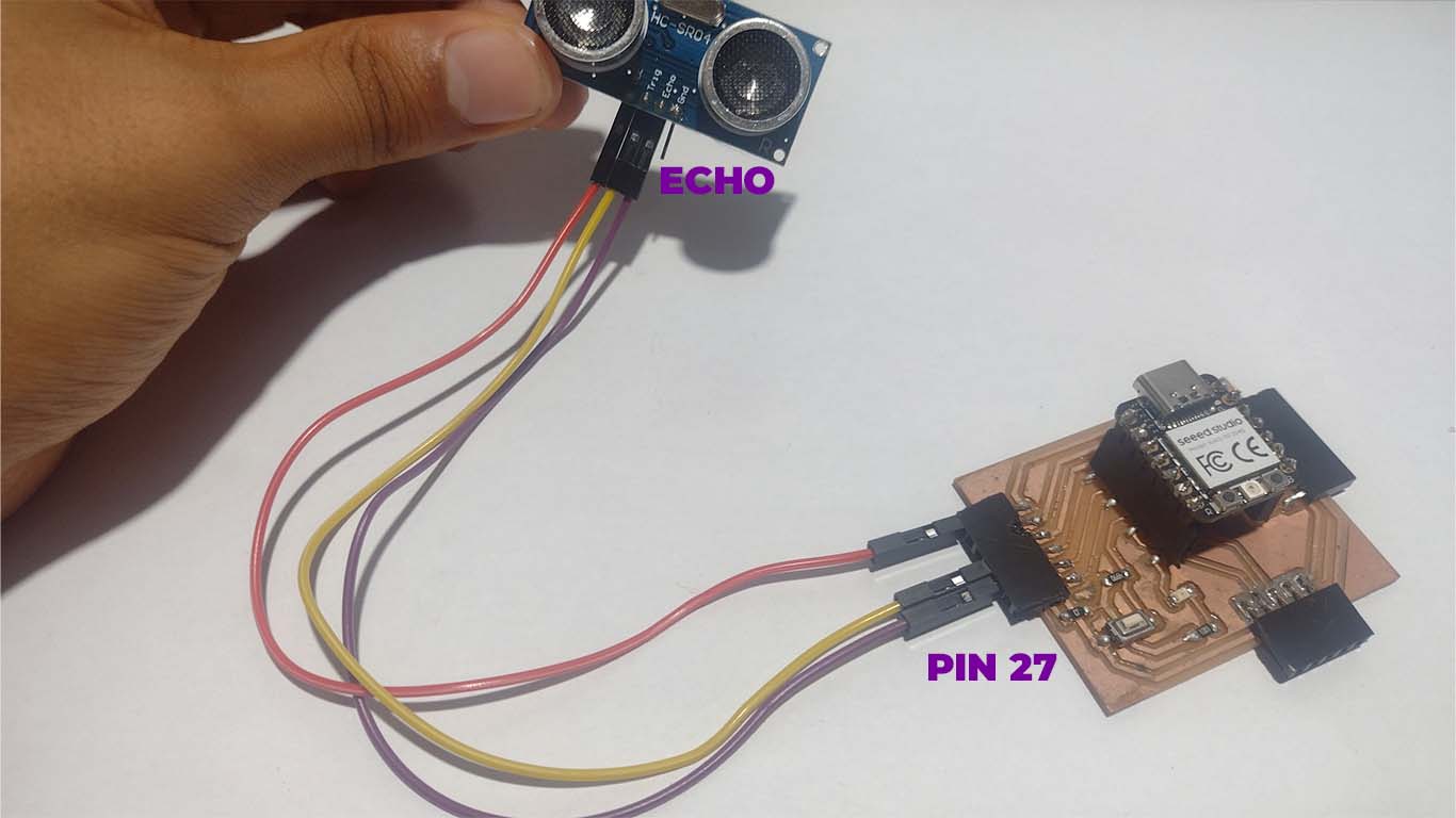
Likewise, we will also place the ECHO PIN of the sensor on one of the pins of the XIAO RP2040. For this I chose the connector that communicates with PIN 27.
Finally, we will connect the GND PIN of the sensor with the GND of the development board. To identify it I placed brown cable.
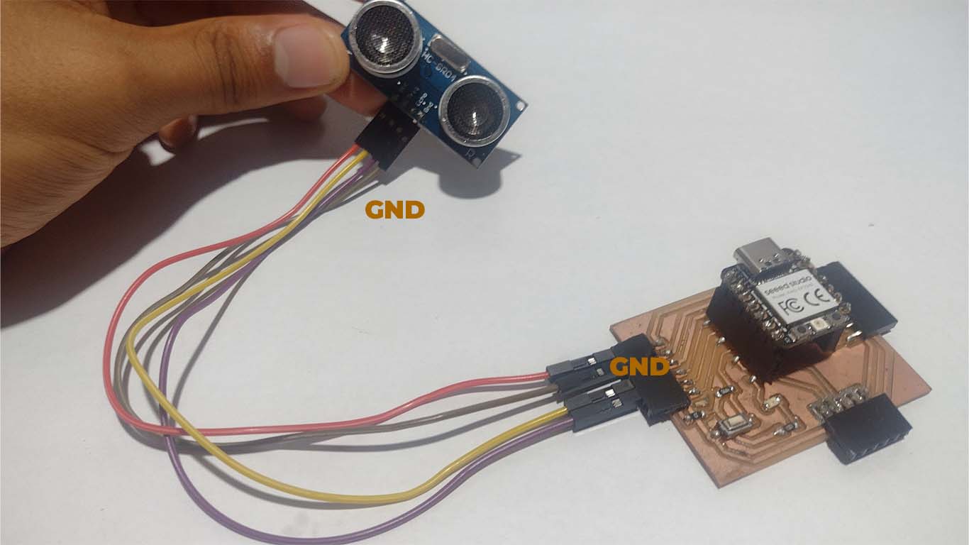
Here is a small photograph of the summary of the connection of the ultrasonic sensor with my HM development board
For programming, I used the ARDUINO IDE, here is the code I used.
                                // Define the pins for the ultrasonic sensor
                                    const int pinTrig = 26;
                                    const int pinEcho = 27;

                                    void setup() {
                                    // Start serial communication
                                    Serial.begin(9600);
                                    // Configure the pins for the ultrasonic sensor
                                    pinMode(pinTrig, OUTPUT);
                                    pinMode(pinEcho, INPUT);
                                    }

                                    void loop() {
                                    // Send a short pulse to the TRIG pin
                                    digitalWrite(pinTrig, LOW);
                                    delayMicroseconds(2);
                                    digitalWrite(pinTrig, HIGH);
                                    delayMicroseconds(10);
                                    digitalWrite(pinTrig, LOW);

                                    // Read the response time from the ECHO pin
                                    long duration = pulseIn(pinEcho, HIGH);

                                    // Calculate the distance in centimeters
                                    int distance_cm = duration * 0.034 / 2;

                                    // Print the distance on the serial port
                                    Serial.print("Distance: ");
                                    Serial.print(distance_cm);
                                    Serial.println(" cm");

                                    // Wait for a brief period of time before the next reading
                                    delay(1000);
                                    }
Here is a sample video, where we see that the sensor sends a signal in SERIAL when it detects MOVEMENT and OFF when it does not detect movement.
TIME OF FLIGHT DISTANCE - VL53L1X
Now we will work with the time of flight distance sensor is a device that uses the time it takes for a pulse of light to travel from the sensor to an object and back to calculate the distance between the sensor and the object, commonly used in applications of Accurate distance measurement.
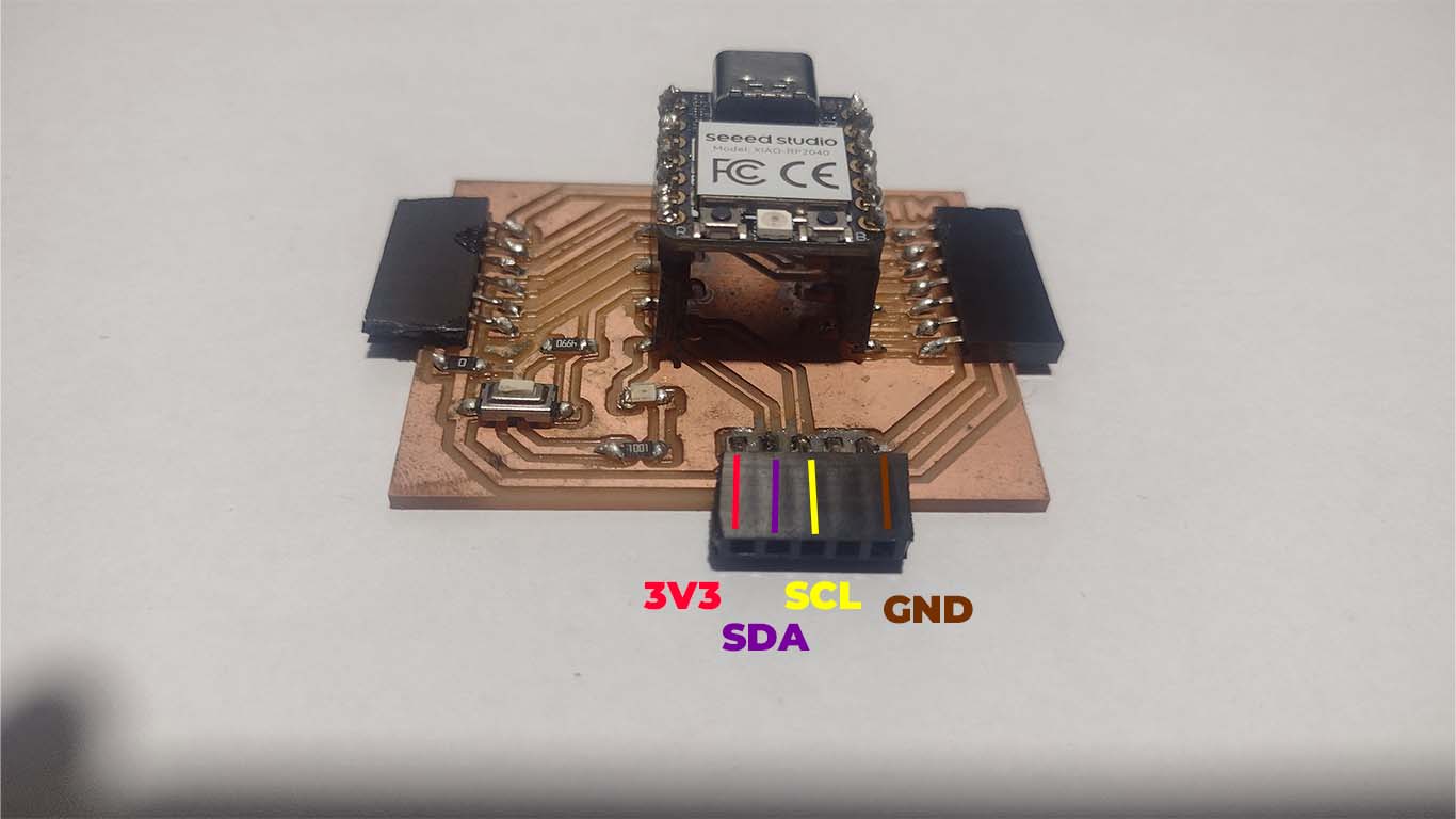
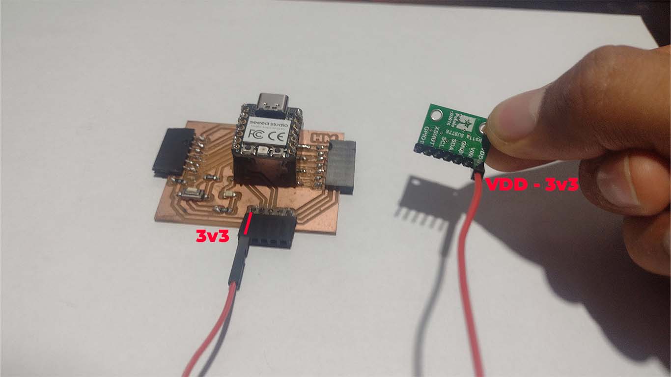
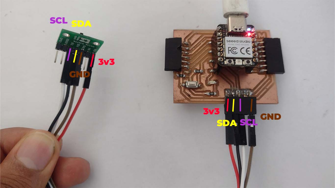
In order to program the time of flight distance, we have to have the I2C inputs, which are made up of the SDA and SCL pins that the XIAO RP2040 has. In my case, my development board has these inputs at the bottom, here is a photograph of the pins.
First we connect the VDD or 3v3 pin of the sensor with the connector that has 3v3 on our development board. To identify it I used the red wire.
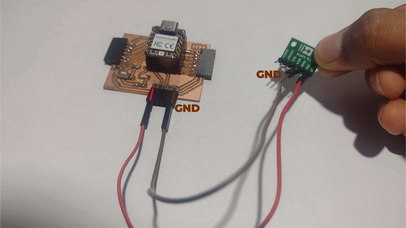
I then connected the GND pins on both the sensor and the development board. The cable color I chose was brown.
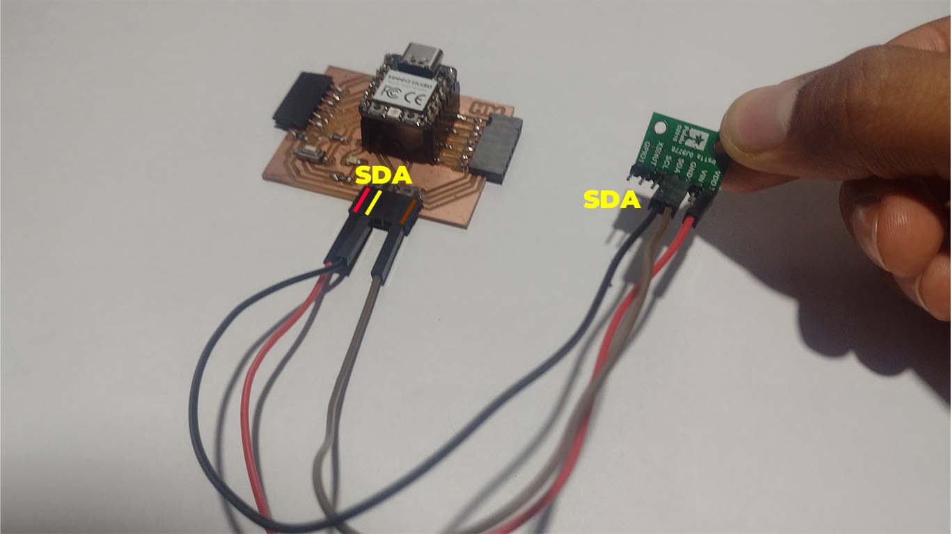
Then we connect the SDA PIN that the sensor has with the SDA PIN of our development board and in the XIAO RP2040 it is PIN 6.
Then we connect the SCL pin of our sensor also to the development board. For the XIAO RP2040 the SCL PIN is PIN 7.
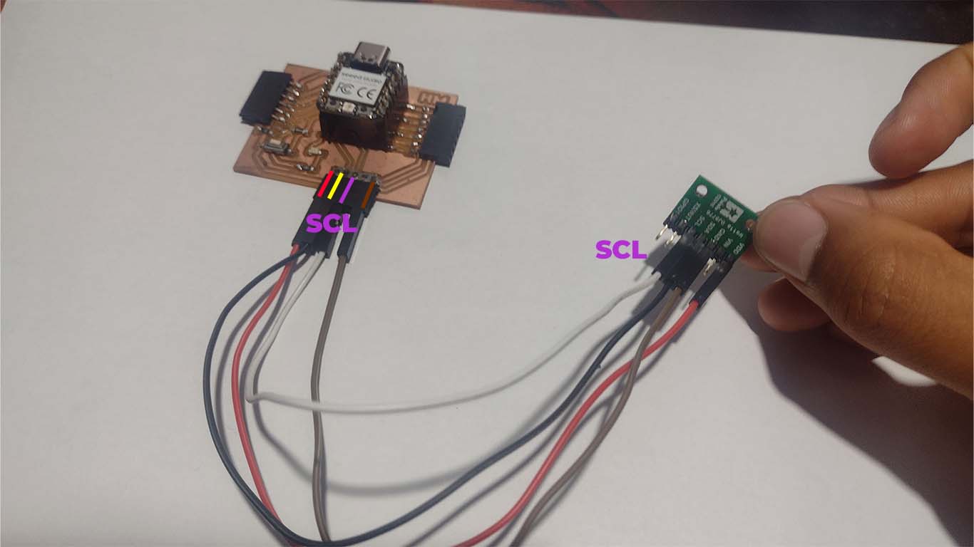
Finally we make all the connections correctly. Here is a summary photograph of my connection.
Now we will move on to programming the sensor with ARDUINO IDE. To do this we have to follow the following steps and we can program, we have to install some libs which is important for programming.
In order to program the time of flight distance VL53L0X we need to install the Pololu library as we can see in the photograph. To carry out this programming I reviewed Adrian Torres' documentation, which helped me a lot to achieve. Here I leave the link to his page so you can see if they have this component or another similar one since he presents many more.
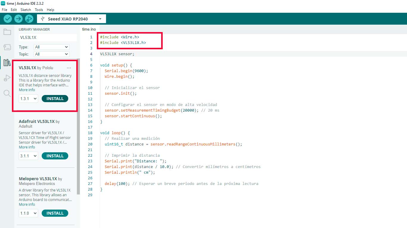
Remember to put < and > symbols in libraries.
                                #include Wire.h
                                    #include VL53L1X.h

                                    VL53L1X sensor;

                                    void setup() {
                                      Serial.begin(115200);
                                      Wire.begin();
                                      Wire.setClock(400000); // Use I2C at 400 kHz

                                      sensor.setTimeout(500);
                                      if (!sensor.init()) {
                                        Serial.println("Error detecting and initializing the sensor!");
                                        while (1);
                                      }

                                      // Use long distance mode and allow up to 50000 us (50 ms) for a measurement.
                                      // You can adjust these values to change the sensor's performance, but
                                      // the minimum measurement time is 20 ms for short distance mode and 33 ms for
                                      // medium and long distance modes. See the VL53L1X datasheet for more
                                      // information on range and timing limits.
                                      sensor.setDistanceMode(VL53L1X::Long);
                                      sensor.setMeasurementTimingBudget(50000);

                                      // Start continuous readings at a rate of one measurement every 50 ms (the
                                      // period between measurements). This period should be at least as long as the
                                      // timing budget.
                                      sensor.startContinuous(50);
                                    }

                                    void loop() {
                                      // Read distance in millimeters
                                      uint16_t distance_mm = sensor.read();

                                      // Convert millimeters to centimeters
                                      float distance_cm = distance_mm / 10.0;

                                      // Print the distance in centimeters
                                      Serial.print("Distance: ");
                                      Serial.print(distance_cm);
                                      Serial.println(" cm");

                                      // Wait for a second before the next reading
                                      delay(1000);
                                    }
Here is a video of the operation of the time of flight distance programmed with Arduino IDE.
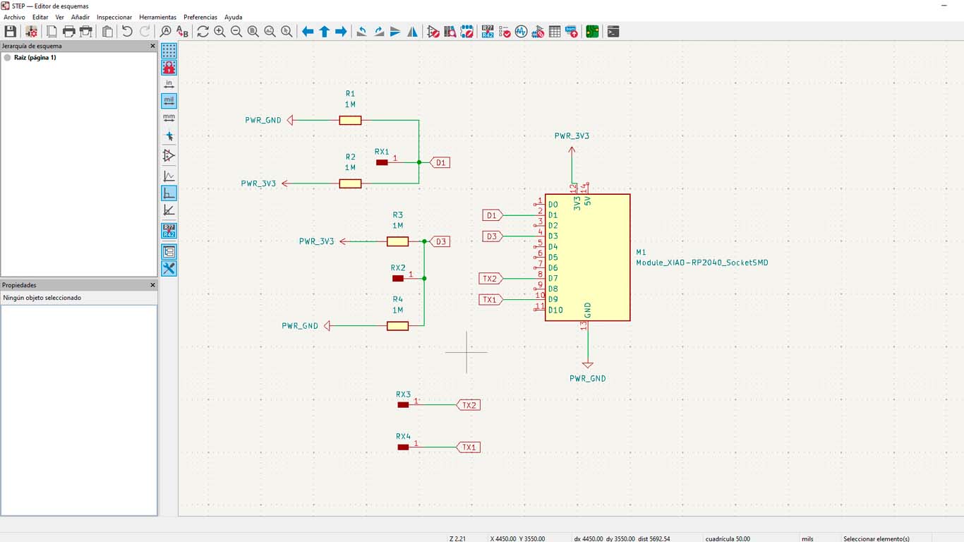
STEP RESPONDE WITH XIAO RP2040
For the step response, I wanted to design it in KICAD so I could mill it. I was guided by NEIL's example that he made and presented in the FAB ACADEMY class. Here is a photograph of the schematic design of the board to achieve STEP RESPONSE input
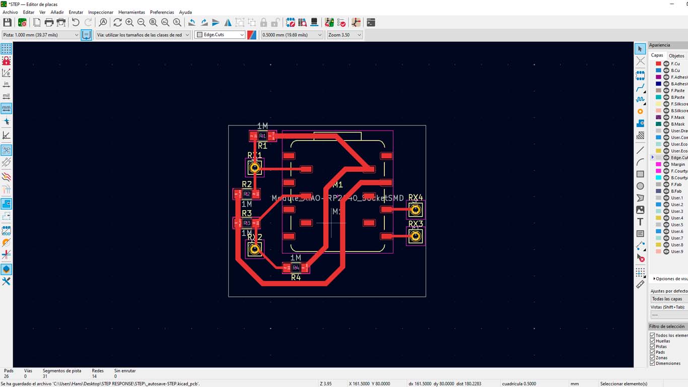
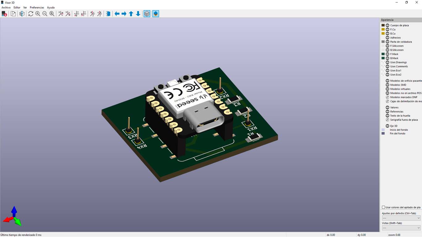
Then I started designing and locating the components we need to achieve STEP RESPONSE. Here is a screenshot of how the new plate will look.
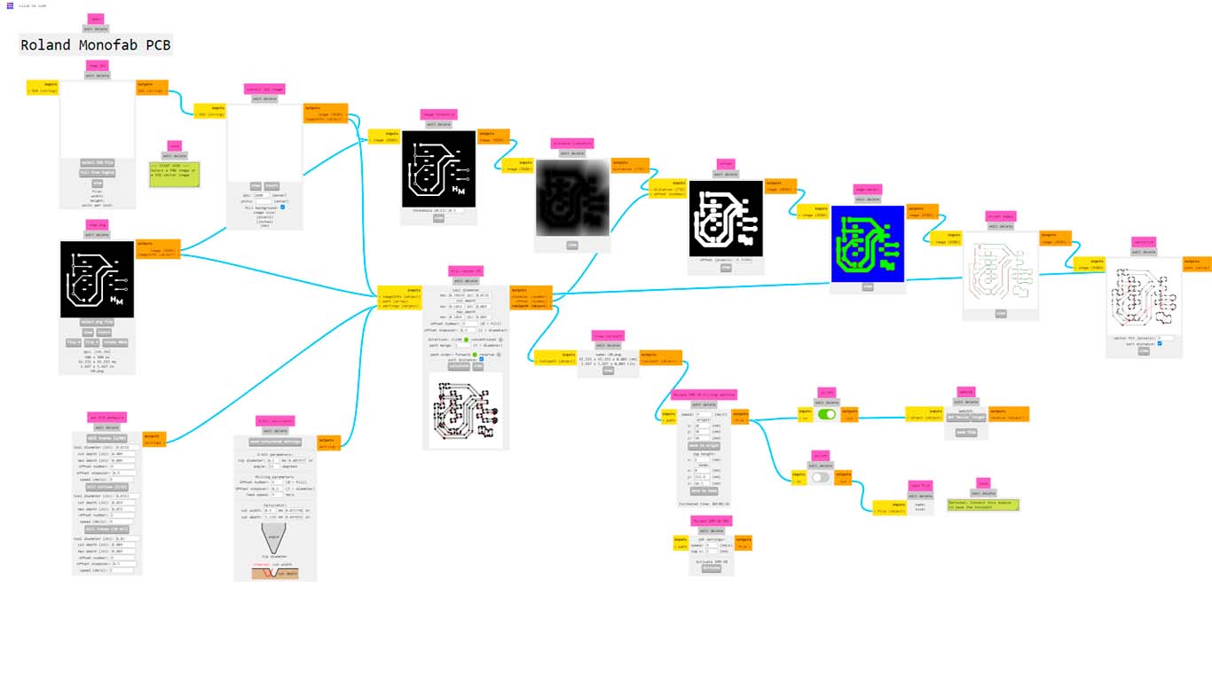
Then we entered MODS to obtain the files to be able to mill the board for the STEP RESPONSE input.
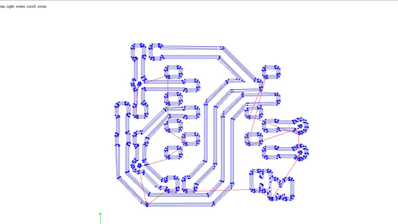
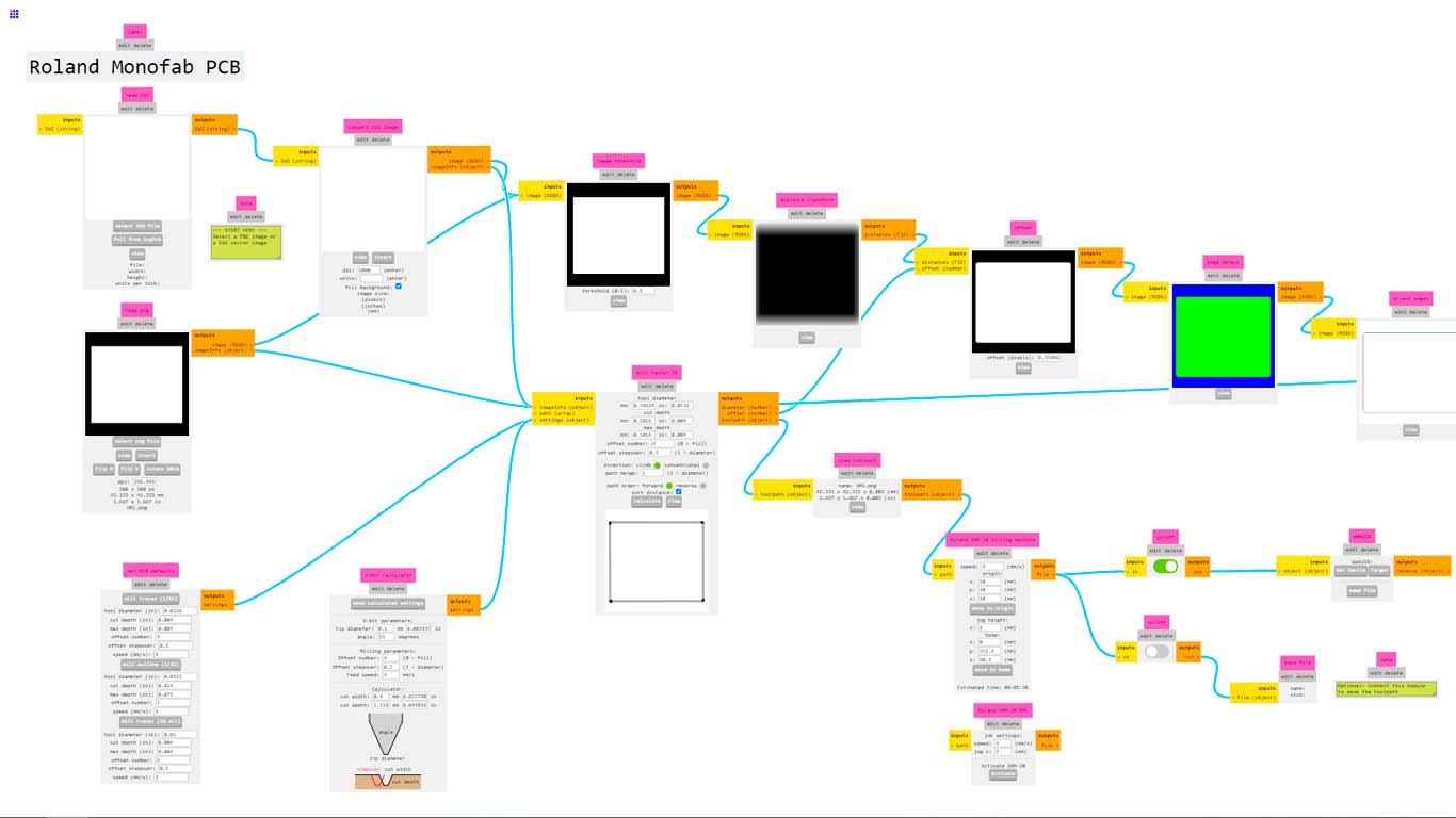
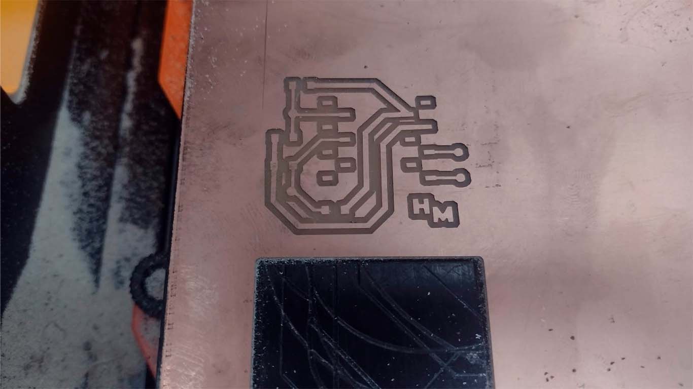
Then we make the perimeter of the plate also in MODS, remember that this process is done with the 1/32 milling cutter.
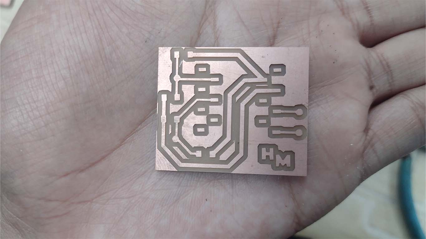
After configuring and obtaining the MODS CE files. We will move on to milling the designed plate, here are some photographs of the result on the ROLAND SRM 20
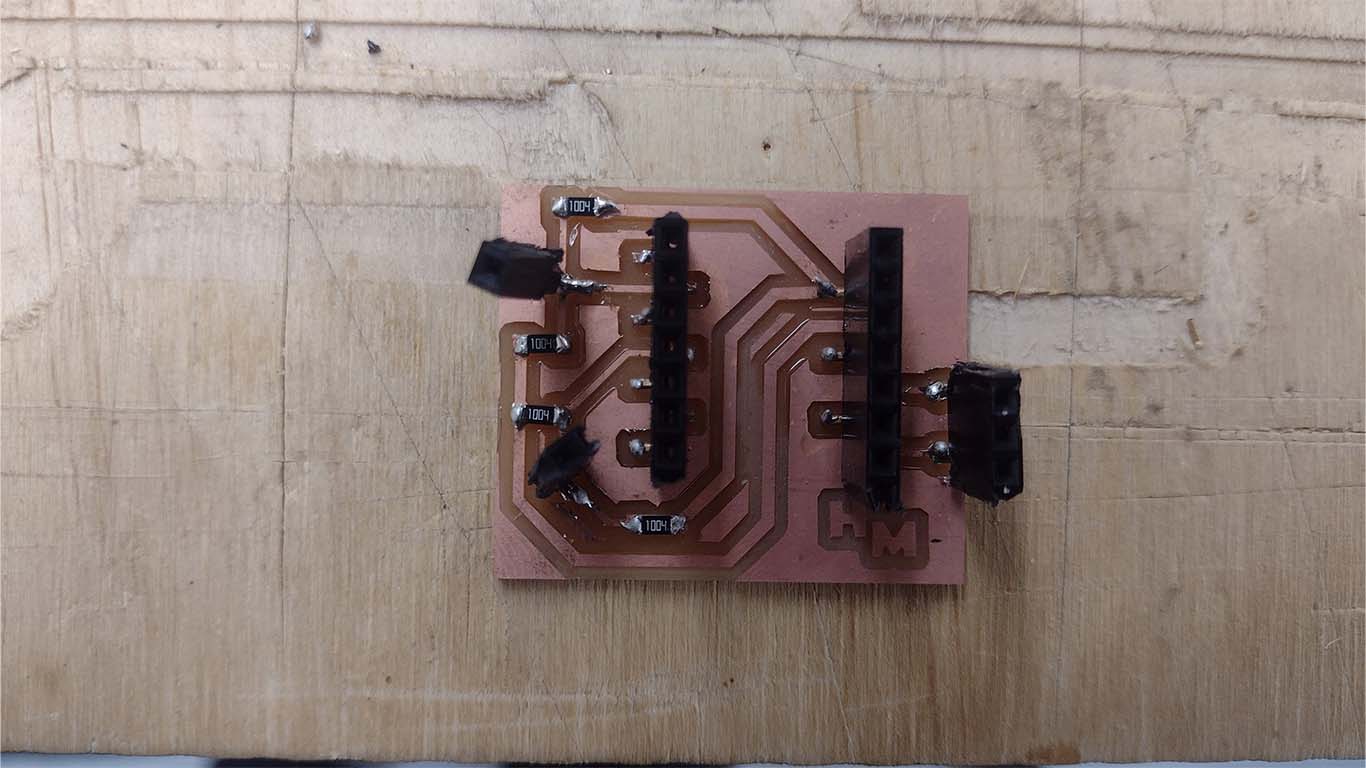
After milling the board, it is our turn to solder the components such as the female connectors and resistors according to our schematic design of the new STEP RESPONSE board.
Then, using connector cables, we solder our 4 copper plates, if possible of the same size. Here I used some plates that were about to be thrown away because I thought they could be used for this assignment. These will capture the pressure signal and are connected to the pins of the XIAO RP2040.
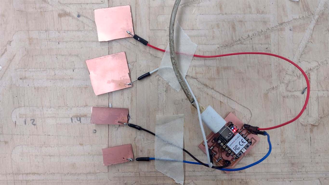
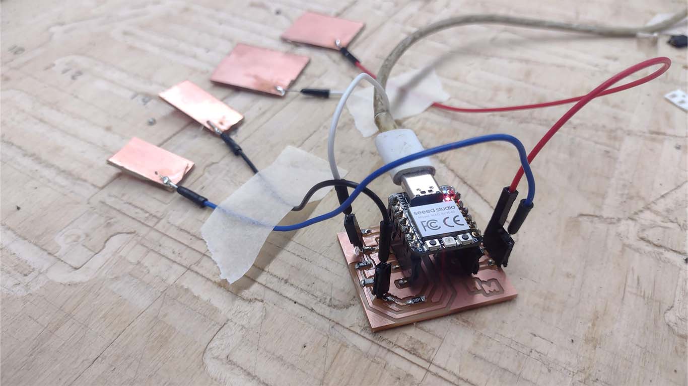
After carefully checking the connection with the multimeter to see if there is continuity in all of them, we can connect the XIAO RP2040 with our computer. Now we will move on to programming the microcontroller and here I leave the programming for ARDUINO IDE.
                                #define digitalWriteFast(pin,val) (val ? sio_hw->gpio_set = (1 << pin) : sio_hw->gpio_clr = (1 << pin))
                                #define digitalReadFast(pin) ((1 << pin) & sio_hw->gpio_in)

                                #define Rx1 27 // receive 1 pin (D1)
                                #define Tx1 4 // transmit 1 pin (D9)
                                #define Rx2 29 // receive 2 pin (D3)
                                #define Tx2 1 // transmit 2 pin (D7)
                                #define settle 20 // settle time
                                #define samples 2000 // number of samples to accumulate

                                void setup() {
                                   Serial.begin(115200);
                                   }

                                void loop() {
                                   }

                                void setup1() {
                                   pinMode(Tx1,OUTPUT);
                                   pinMode(Tx2,OUTPUT);
                                   }

                                void loop1() {
                                   int32_t up1,down1,up2,down2;
                                   up1 = down1 = up2 = down2 = 0;
                                   for (int i = 0; i < samples; ++i) {
                                      digitalWriteFast(Tx1,HIGH); // charge up
                                      up1 += analogRead(Rx1); // read
                                      delayMicroseconds(settle); //settle
                                      digitalWriteFast(Tx1,LOW); // charge down
                                      down1 += analogRead(Rx1); // read
                                      delayMicroseconds(settle); // settle
                                      digitalWriteFast(Tx2,HIGH); // charge up
                                      up2 += analogRead(Rx2); // read
                                      delayMicroseconds(settle); //settle
                                      digitalWriteFast(Tx2,LOW); // charge down
                                      down2 += analogRead(Rx2); // read
                                      delayMicroseconds(settle); // settle
                                      }
                                   Serial.print(up1-down1); // send difference
                                   Serial.print(',');
                                   Serial.println(up2-down2); // send difference
                                   Serial.flush(); // finish communicating before measuring
                                   }
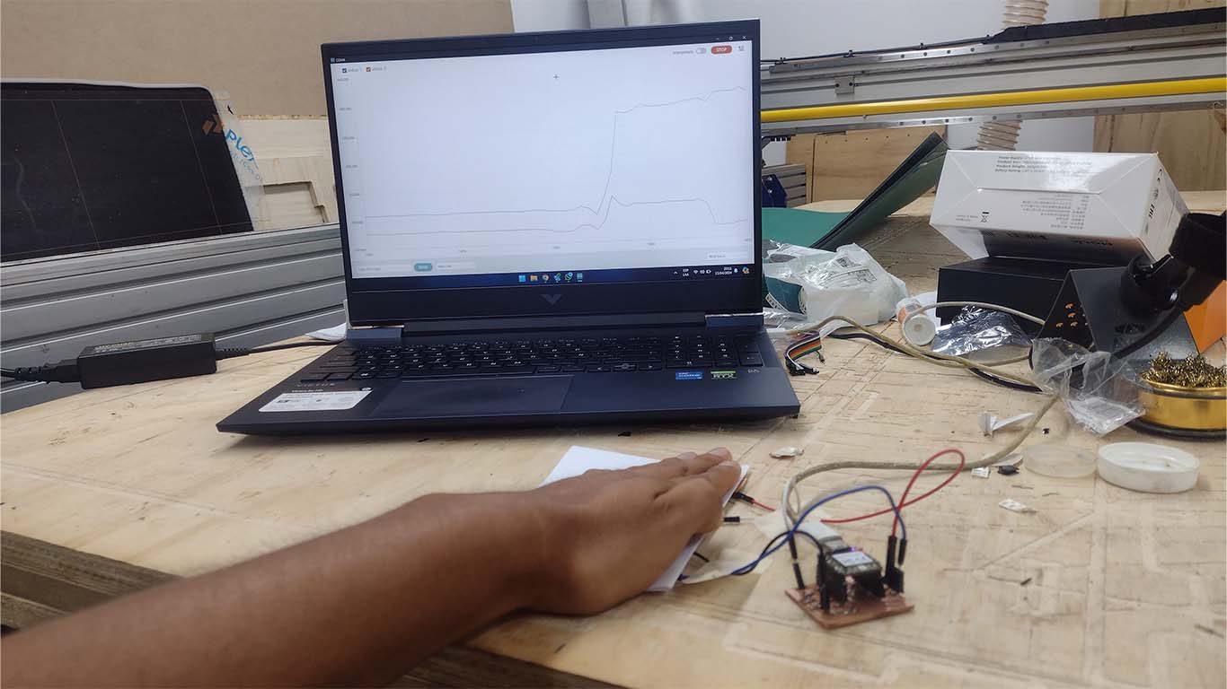
After programming and reviewing each line of the programming, I began to carry out the tests and I was surprised by the result. Here is a photograph of the moment and a video showing how STEP RESPONSE works with only small copper plates that receive the signal and the pressure level.
REVIEW OF THE CLASS
During the review of this class I volunteered in the minute 1:23:06
Clic here to 220240417 review from Academany on Vimeo.
FILES
Here you can download all the files that I have made for the following assignment: