This week's assignment was:
- Measure the power consumption of an output device
- Add an output device to a microcontroller board you've designed, and program it to do something
ORGANIZATION
Here I show how I organized myself for this week.
| Wednesday 20th: | Fab Academy classes, organization for the week and review of the operation of my boards developed last week. |
|---|---|
| Thursday 21th: | Design and milling of a new development board. Review of the FAB LAB OUTPUTS. |
| Friday 22th: | Soldering and programming of OUTPUTS of new development board. |
| Saturday 23th: | Enter OPEN GLOBAL TIME, learn more about the assignment and complete the group assignment. |
| Sunday: 24th: | Carry out documentation of everything developed. |
| Monday 25th: | Review and correction of documentation. Update and changes for last commit. |
| Tuesday 26th: | Documentation and last commit of the week. |
GROUP ASSIGNMENT
Here I leave the link to go to the group assignments page.
Clic here to visit the WEEK 9 GROUP ASSIGNMENT PAGE
MEASURING CONSUMPTION POWER
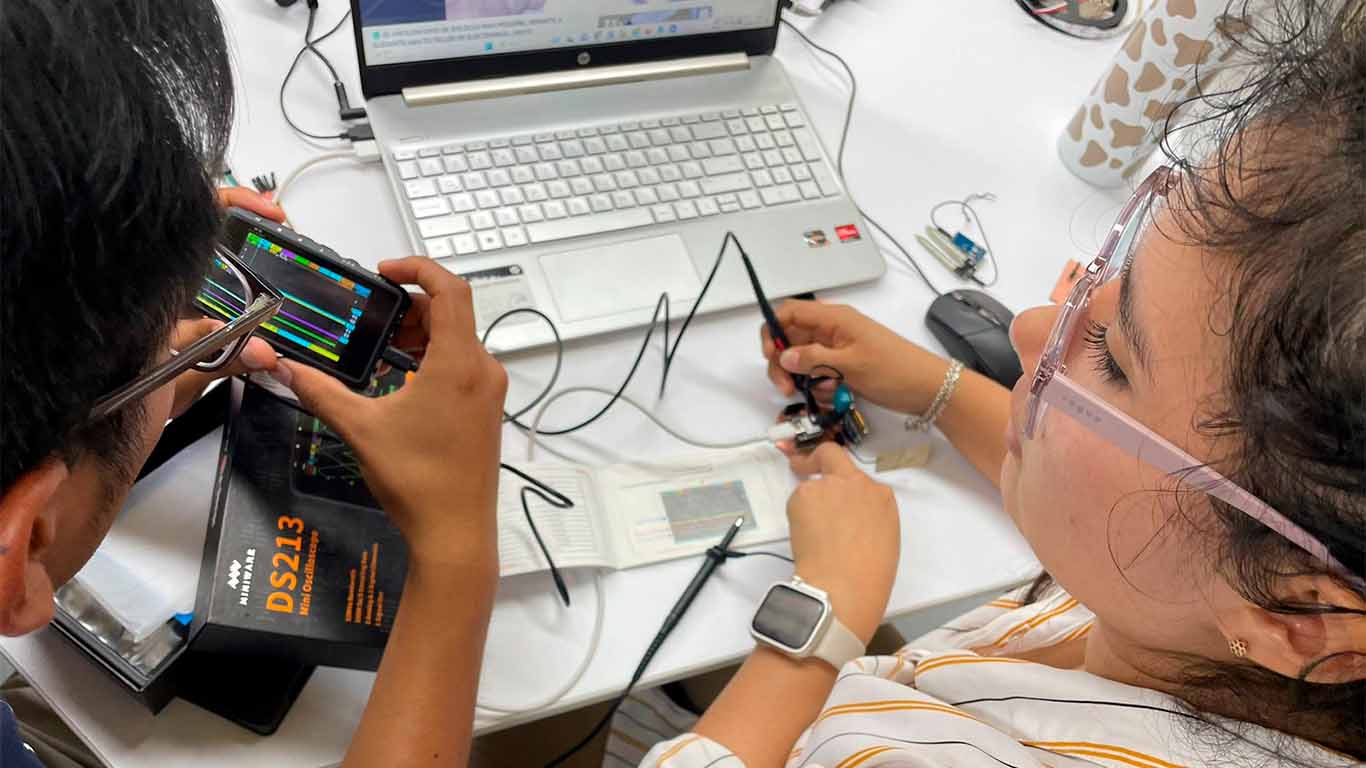
For group development we decided to measure the outputs of each one with their own boards developed last week. The idea was to learn how to measure AMPS, VOLTS and replicate it on each board. In my case, I used the SERVO MOTOR, OLED SCREEN and NEOPIXEL LED.
To carry out the OUTPUTS DEVICE week, I decided to make a new board solving the errors that I had in the last week, I did not focus much on the design but more on the operation to be able to develop the individual and group assignment. Then I modified and redesigned the plate, here is my group order.
SERVO MOTOR - VOLTAGE
To measure the power consumption, I first use the multimeter and also the oscilloscope. Here my analysis of the servomotor:
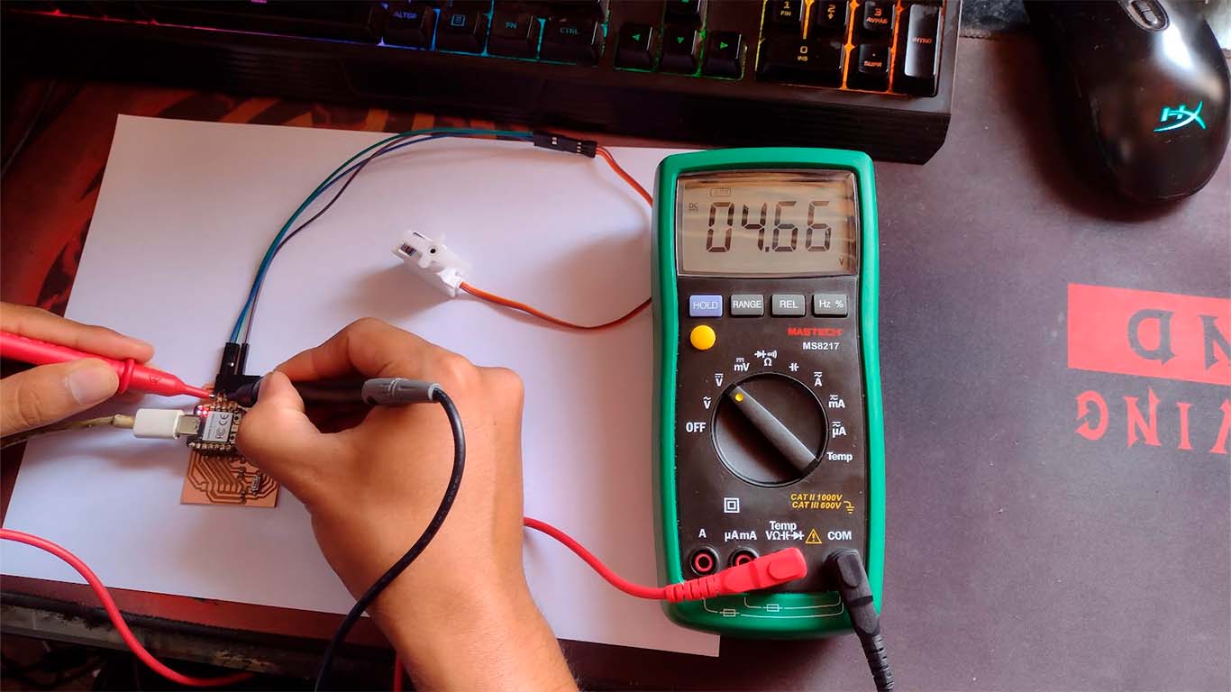
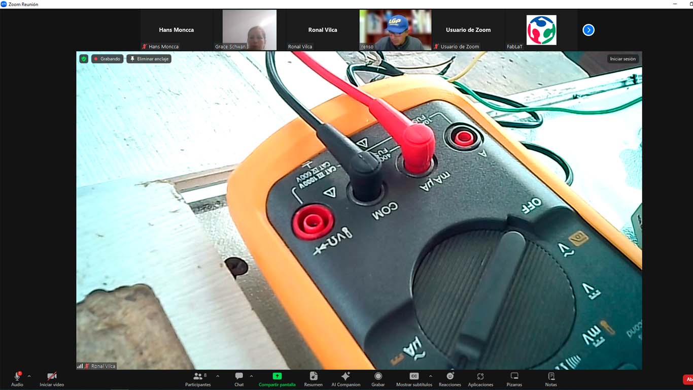
First we measure the VOLTAGE that the SERVOMOTOR needs for its operation, to do this we place the COM of the multimeter in the GND of the SERVOMOTOR and the POSITIVE in the 5V of the MOTOR. This will give us a measurement of 4.65 to 4.68 of the voltage that the SERVOMOTOR needs to operate. Here are some images of how we measure it.
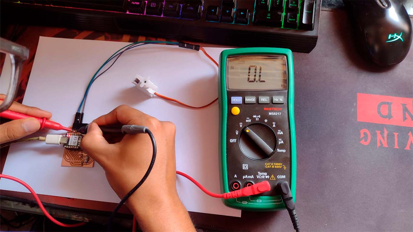
In the video we can see the change in voltage that the SERVOMOTOR has when rotating or changing degrees. We must place the COM AND VOLTAGE points correctly to be able to measure accurately.
SERVO MOTOR - AMPS
Now we will measure the amperes or intensity of the SERVOMOTOR. To do this we need to make a SERIAL connection, where we will place the COM and the mA to another point of the 5V, acting as a bridge. Then we will measure in mA and here the result.
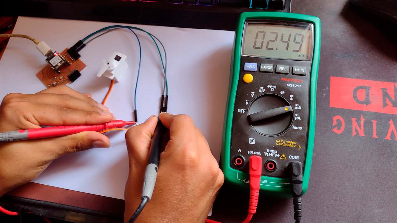
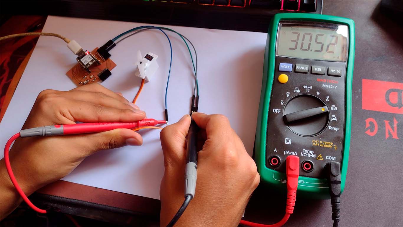
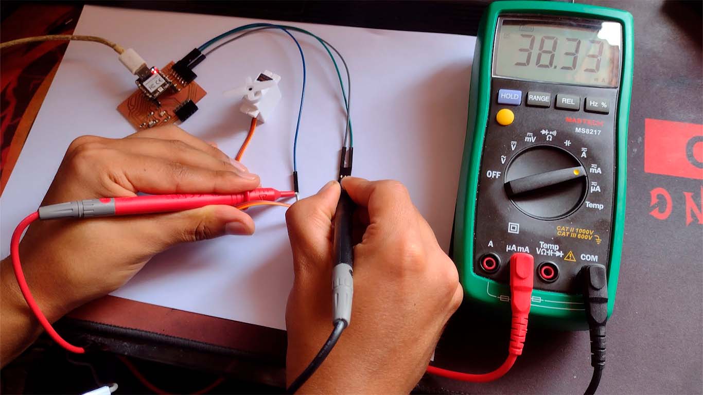
Like voltages, the amperage of the servomotor changes according to the movement made by the output and we can see different values that we obtain.
After obtaining the values of VOLTS (V) and INTENSITY (mA), we can calculate the consumption of the SERVOMOTOR using this formula: WATTS = VOLTAGE (V) X INTENSITY (mA).
| WATTS = VOLTAGE(V) x INTENSITY(A) |
|---|
| W = 4.66v X 0.03033 A = 0.14W |
THE SERVOMOTOR CONSUMES 0.14 WATTS
SERVO MOTOR - OSCILLOSCOPE
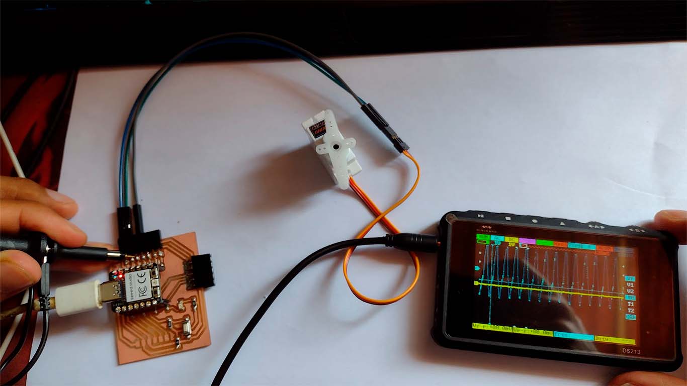
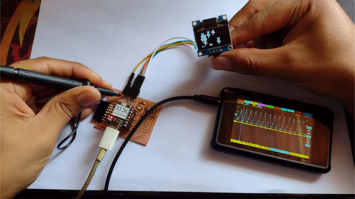
We also analyzed with the oscilloscope where we obtained a WAVE type diagram when we connected the oscilloscope channel to the GND pin of the board. We could see that it was constant, here are some photographs of the measurement.
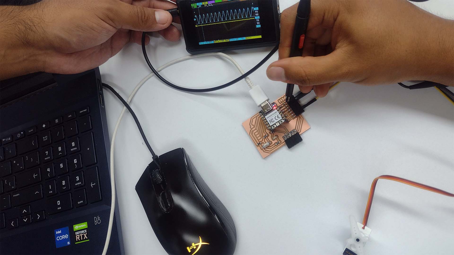
By measuring with the oscilloscope we observe the difference that the waves have with other types. In the following video, we can see the behavior of the OSCILLOSCOPE when we contact the GND and see the data it provides us.
OLED DISPLAY - VOLTAGE
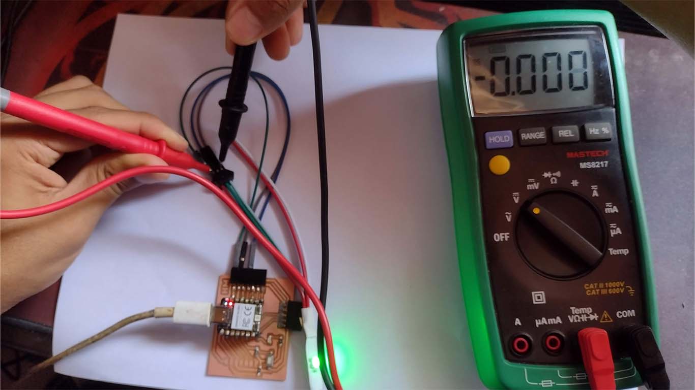
With the multimeter you can also measure the voltages of an OLED. To do this we need to place the COM point of the multimeter at the GND and the mA point at the 3.3V point, both of the OLED. Here we can see how when connecting we obtain the voltage that the OLED receives and has for its operation.
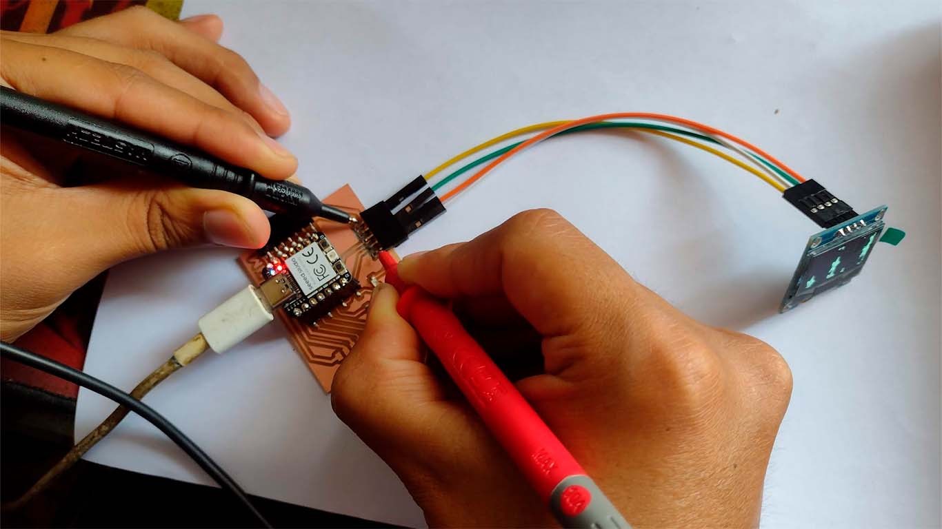
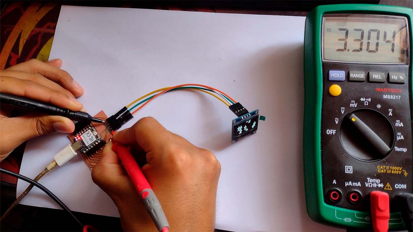
Here I show you a video of how we perform the test with the multimeter. We can see that the value reaches 3.3V that the OLED needs for its operation.
OLED DISPLAY - AMPS
To measure the amperes of an OLED, first we have to disconnect the XIAO RP2040 from the PC, we make the serial connection of the VCC of the OLED with the multimeter and connect the COM on one side and the mA point on the other, where we will see that it turns on the OLED and on the multimeter we can see the amperes it presents. Here are some photographs.
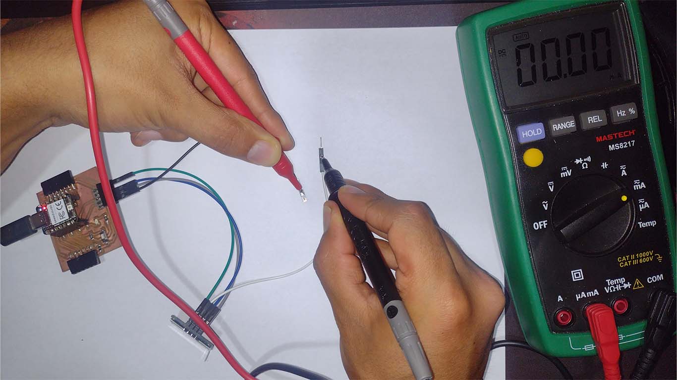
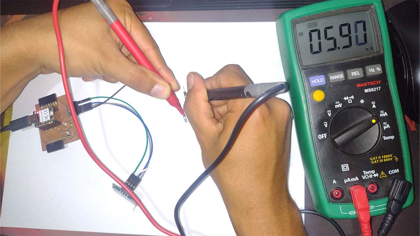
Finally, here is a sample video of how we can obtain the Amperes that the OLED has, in my case I obtained a value of approximately 5.9 mA.
After obtaining the values of VOLTS (V) and INTENSITY (mA), we can calculate the consumption of the OLED using this formula: WATTS = VOLTAGE (V) X INTENSITY (mA).
| WATTS = VOLTAGE(V) x INTENSITY(A) |
|---|
| W = 3.3v X 0.0059 A = 0.019W |
OLED DISPLAY - OSCILLOSCOPE
Now we will use the oscilloscope for the OLED. In this case, we did the tests on each pin that the OLED has and it gave us the same wave signal in each of them, it only changed the intensity and we managed to capture some of them. Here are some photographs of how we did it.

Here is a test video of how we use the oscilloscope on the OLED.
NEOPIXEL - VOLTAGE
Now with the multimeter we measured the VOLTAGE generated for the NEOPIXEL where we obtained a value of 3.411 when measuring it. Here we can take some photographs at the time of measurement.
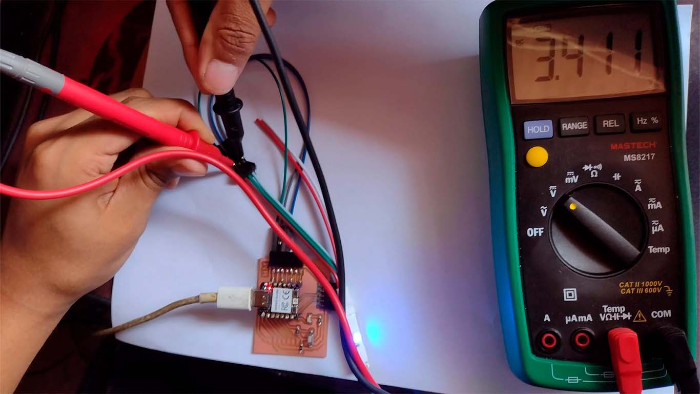
In the following video we can see how the multimeter marks different values that we obtain from the NEOPIXEL voltage.
NEOPIXEL - AMPS
To measure the amperes of the NEOPIXEL, just as with the previous devices, we change the multimeter to AMPERES and see by joining both component poles we can have a value of 6.98 to 7.10 that the multimeter marked for us.
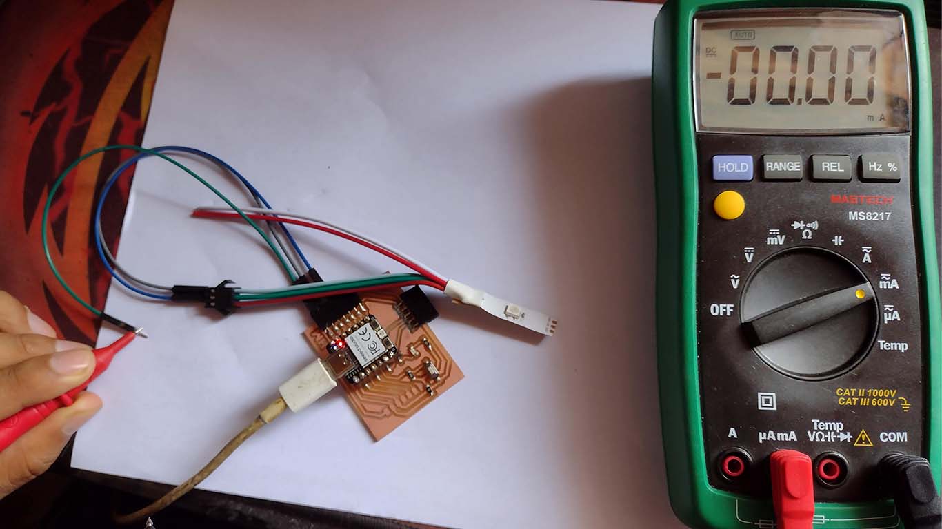
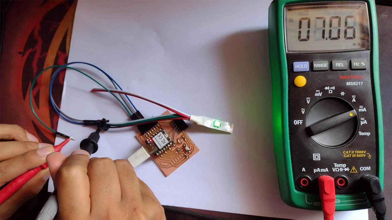
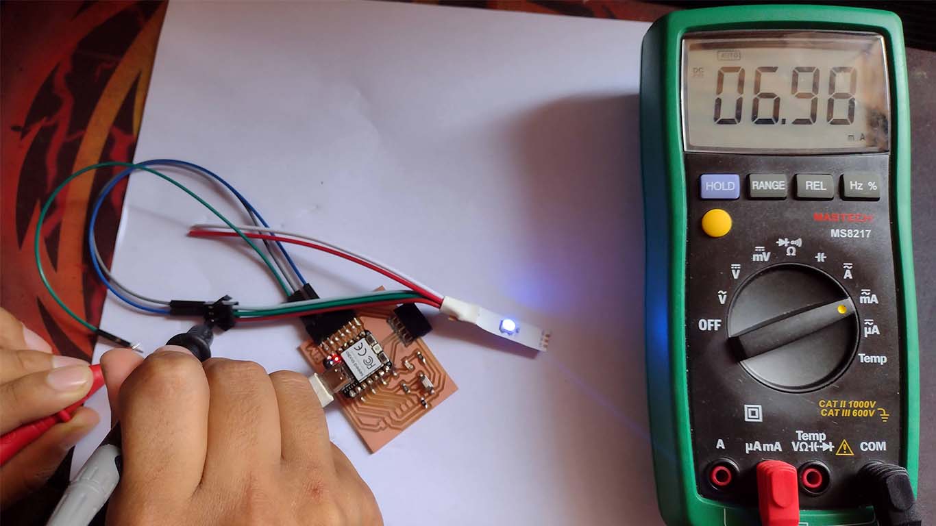
In the video we can see how by connecting the multimeter in series, we can turn on the LED and at the same time obtain the value of AMPERES that we need to know the consumption, where we obtained values less than 7 mA.
After obtaining the values of VOLTS (V) and INTENSITY (mA), we can calculate the consumption of the NEOPIXEL using this formula: WATTS = VOLTAGE (V) X INTENSITY (mA).
| WATTS = VOLTAGE(V) x INTENSITY(A) |
|---|
| W = 3.4v X 0.00668 A = 0.0227 W |
THE NEOPIXEL CONSUMES 0.02 WATTS
NEOPIXEL - OSCILLOSCOPE
With the help of the oscilloscope I was able to analyze the behavior of the waves in the NEOPIXEL. Here are some photographs of them in which we can see that waves continue to be generated when they come into contact with any pin on the board.
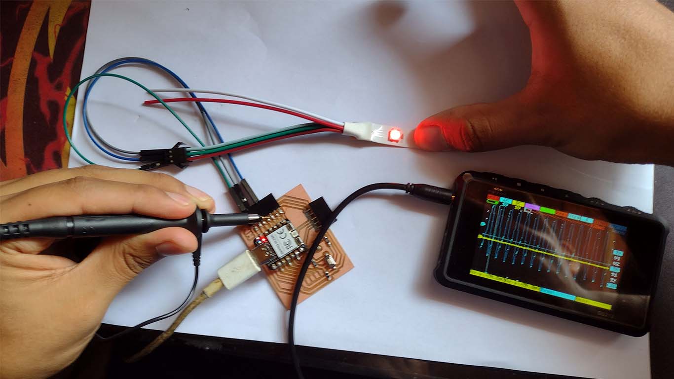
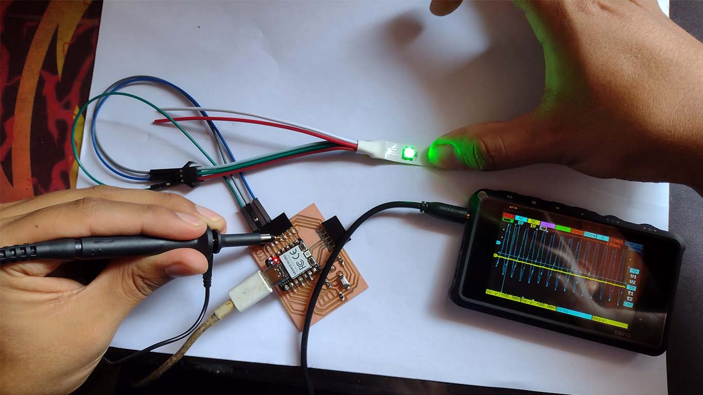
Here in the video we can see the change that is generated in the oscilloscope when I place channel A of the equipment in PIN 3 where we have the DATA that the microcontroller is sending to the neopixel.
IN-PERSON AND ONLINE GROUP MEETINGS
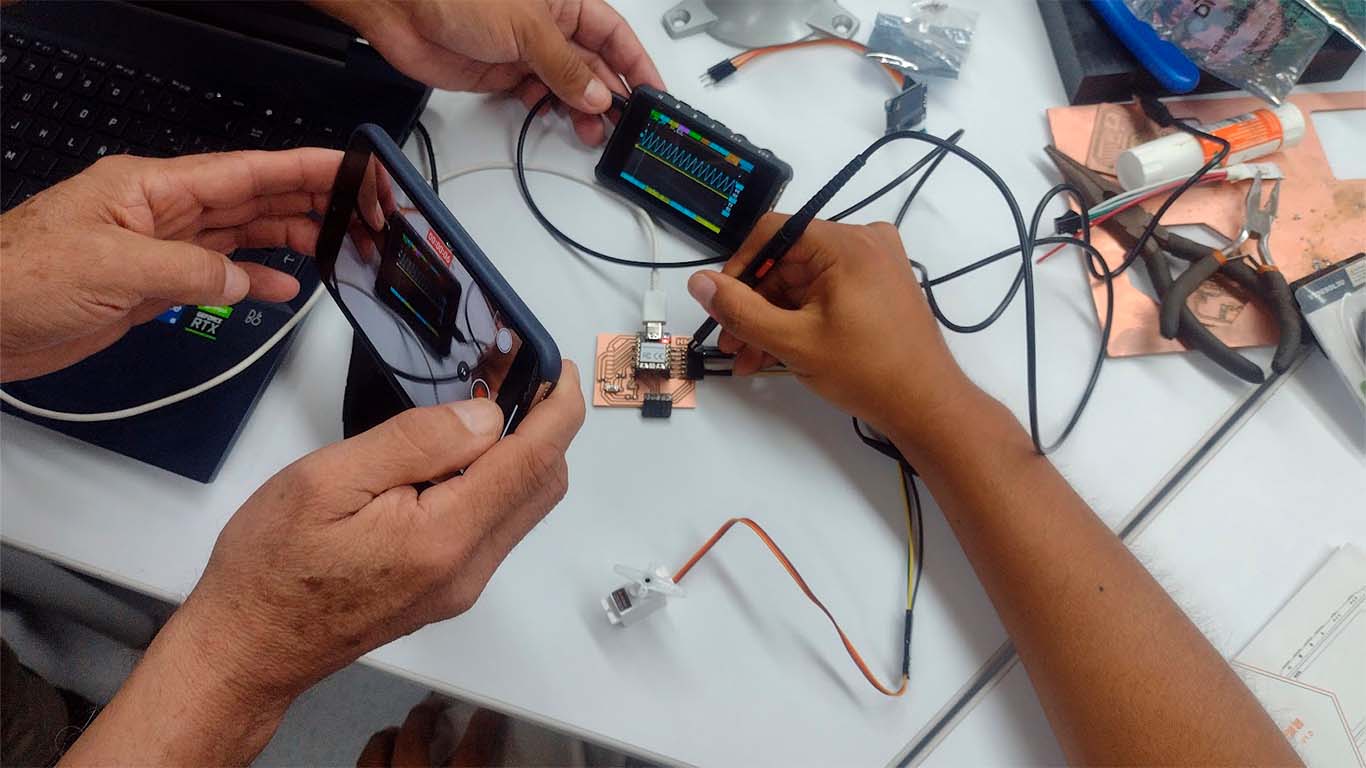
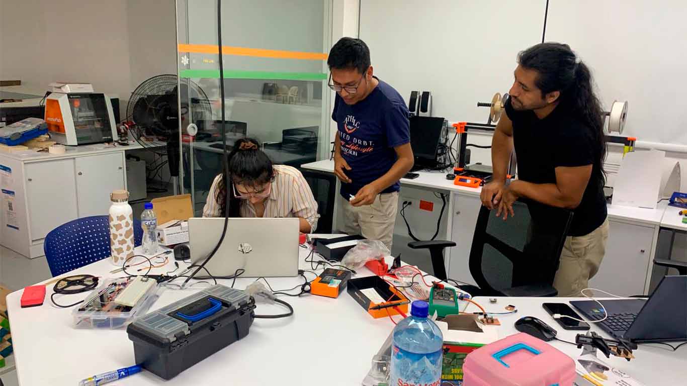
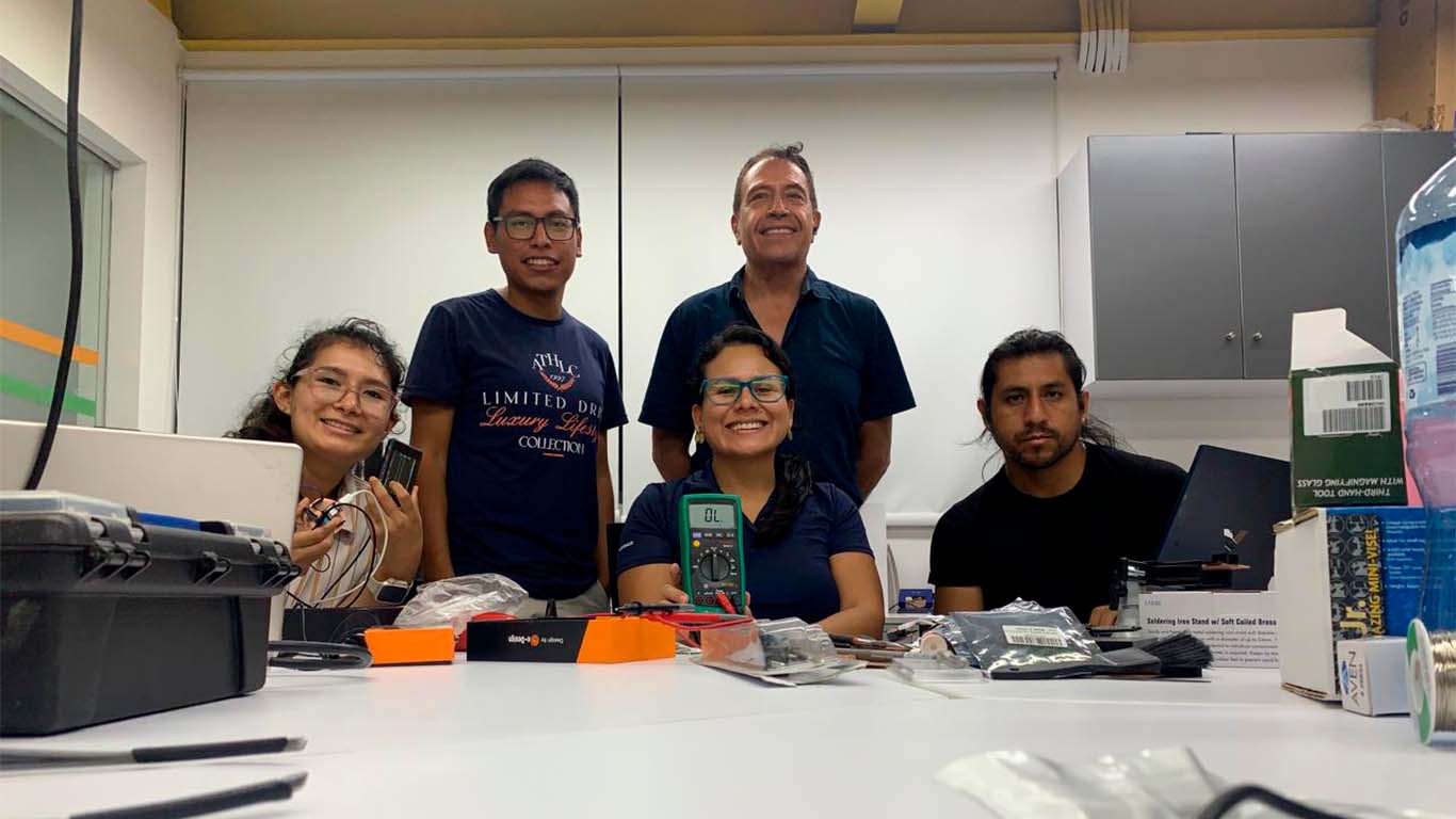
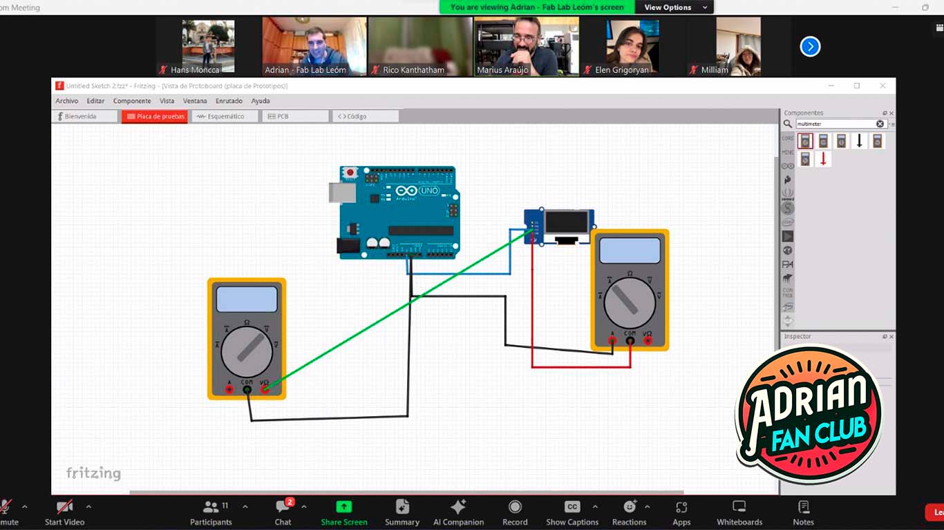
For this group work we met on Saturday at the FAB LAB UCSUR to be able to carry out the group assignment and also support each other with any questions we had and we also joined the GLOBAL OPEN TIME. The next Sunday, we met virtually with other colleagues who are not in Lima to support each other and achieve the group assignment. Here are some photographs from the weekend of outputs devices week.
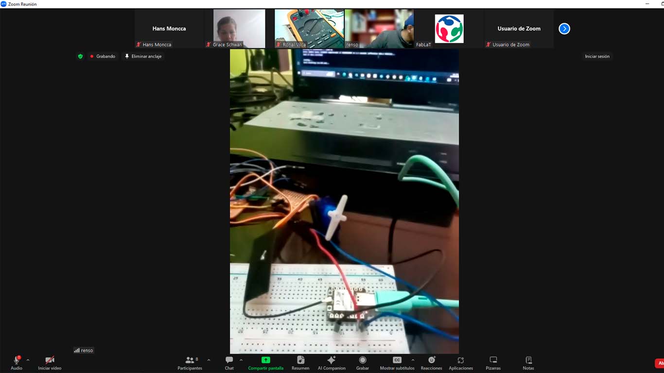
Here are some photographs from our virtual meeting on Sunday.
SUPPORT AND FEEDBACK
FAB ACADEMY SUPPORT
On Saturday as a group we joined the OPEN GLOBAL TIME and as always Adrian, Rico and the other colleagues supported us to resolve our doubts. The truth is that it is very interesting to spend time with them since they answer any questions and also support other colleagues. Thank you very much for another week of teachings, teachers.
INDIVIDUAL ASSIGNMENT
REDESIGNING MY DEVELOPMENT BOARD
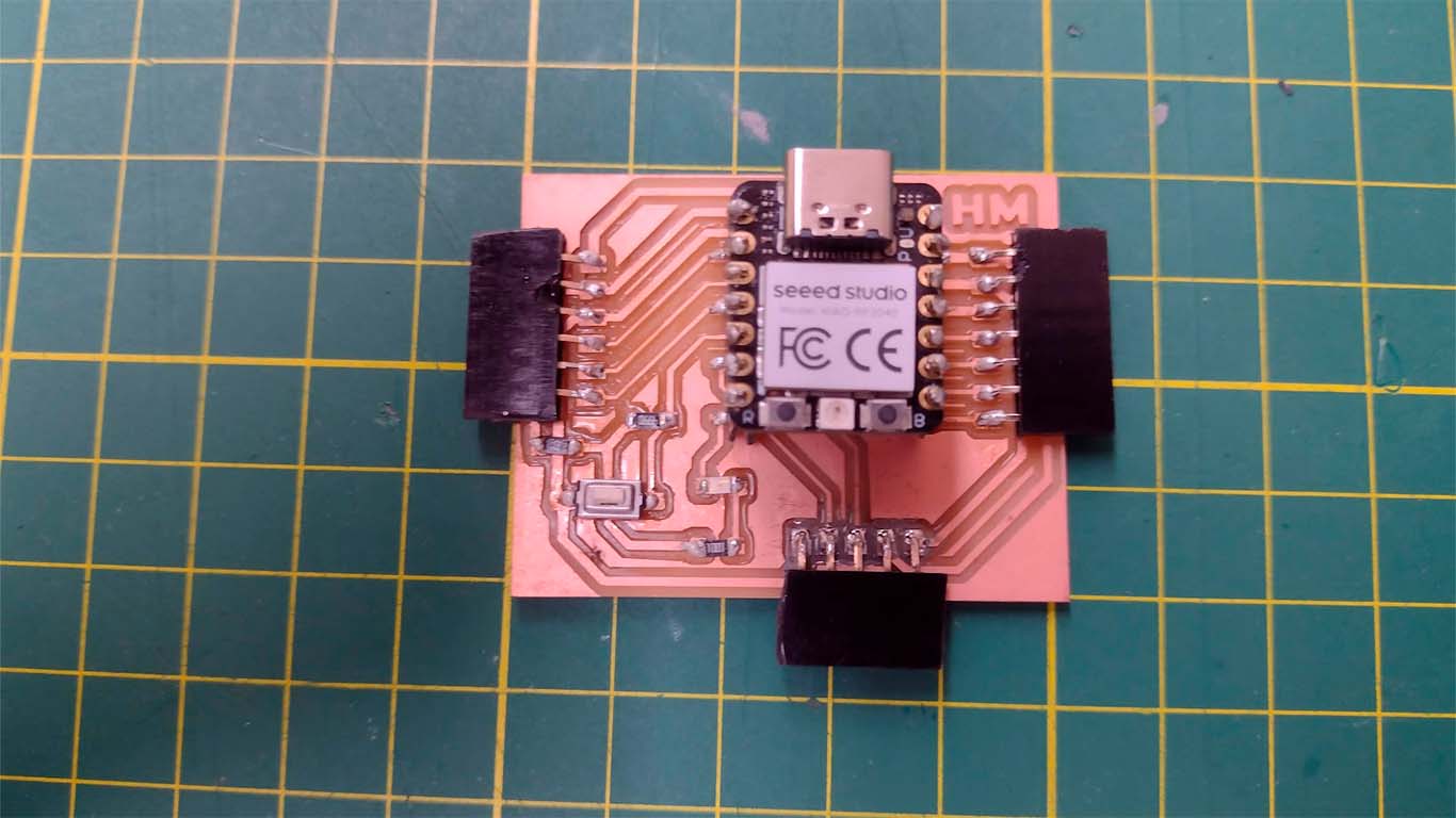
HM DEVELOPMENT BOARD
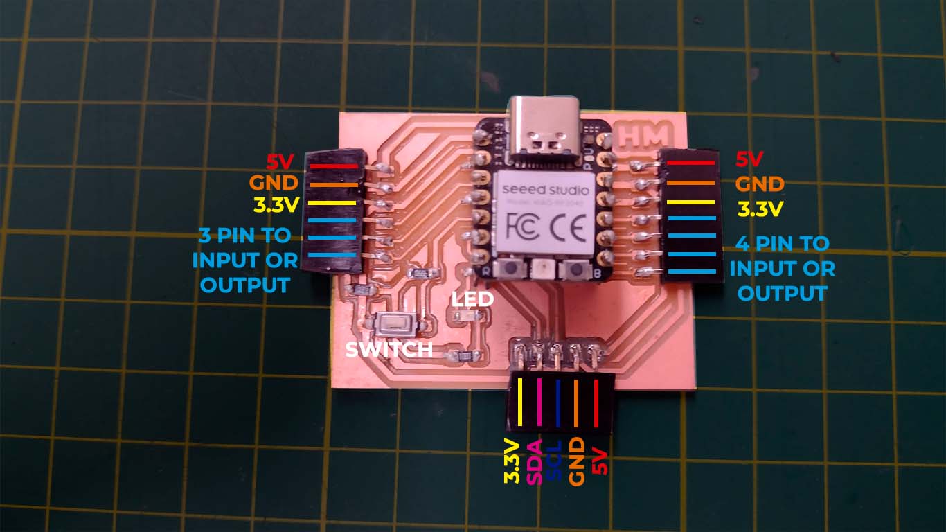
Last week during electronic design week I was able to make my board but not all the pins worked. So for this week I tried to change the design to something simpler but functional. That's why I developed HM, a development board that contains the XIAO to program different outputs. At the Global Open Time they recommended that we could make a board that could accommodate all the outputs of our final projects. So having that premise, I made a new board and here I will work on all the outputs for the week.
DESIGNING IN KICAD
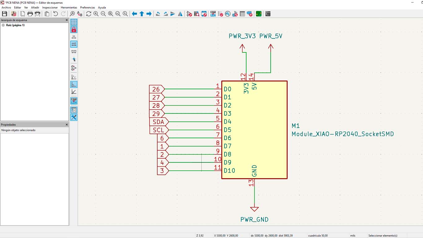
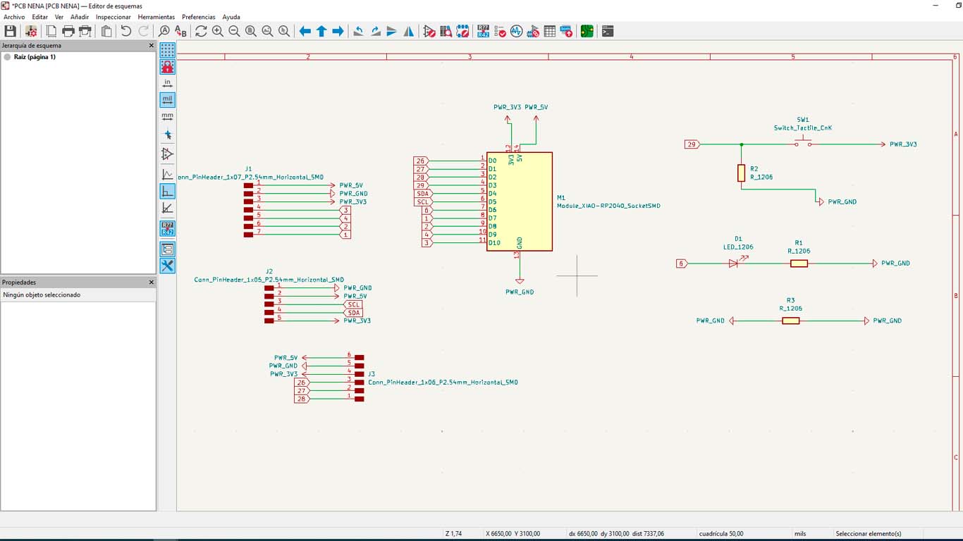
Like the boards developed last week, I will use the XIAO RP 2040 as a microcontroller. The main outputs that I will use for my final project are OLED, SERVOMOTOR AND NEOPIXEL, that is why I will make a board that can program these 3 outputs, so here I added labels to be able to place connectors.
I added 3 controllers, the first is for programming the inputs. The second is intended for I2C outputs, here I will connect the OLED for example to be able to program it and finally a last connector to program different outputs such as servomotor.
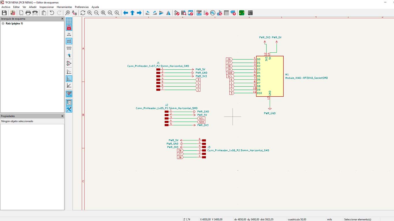
Finally, in the design I added an LED as a recommendation from some instructors to know that the development board is working correctly. So I also added a switch to function as an input for the LED.
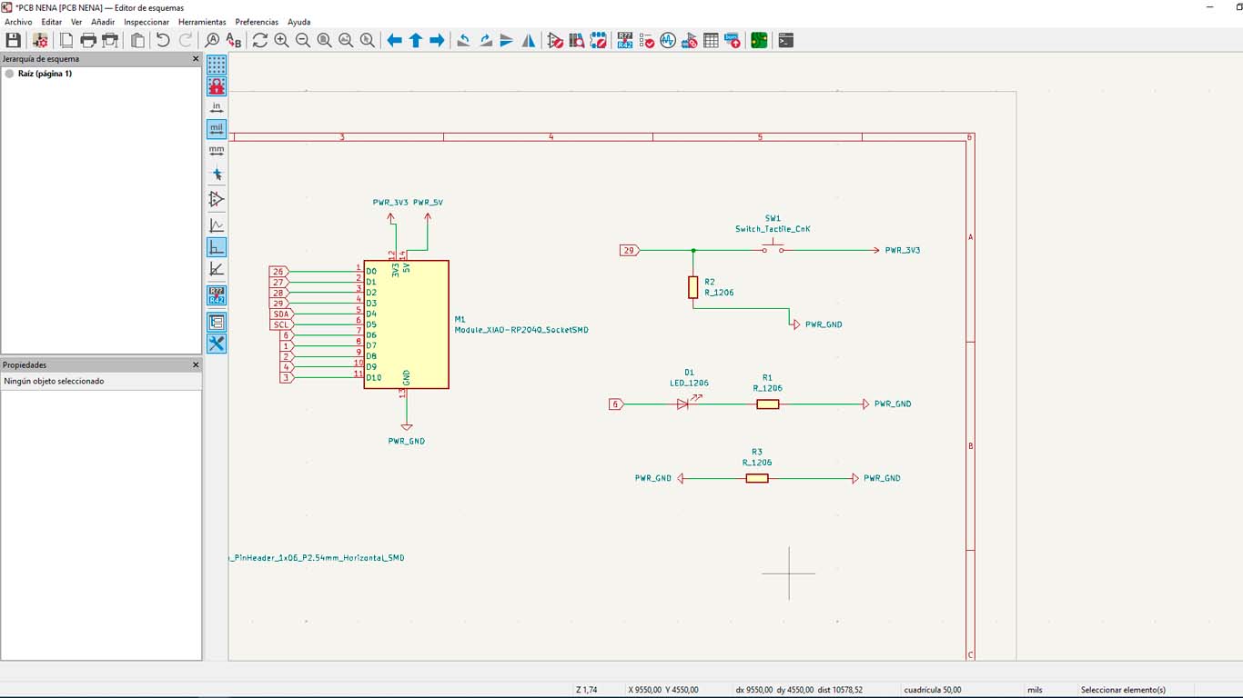
Here is a screenshot of my schematic design of the new HM board
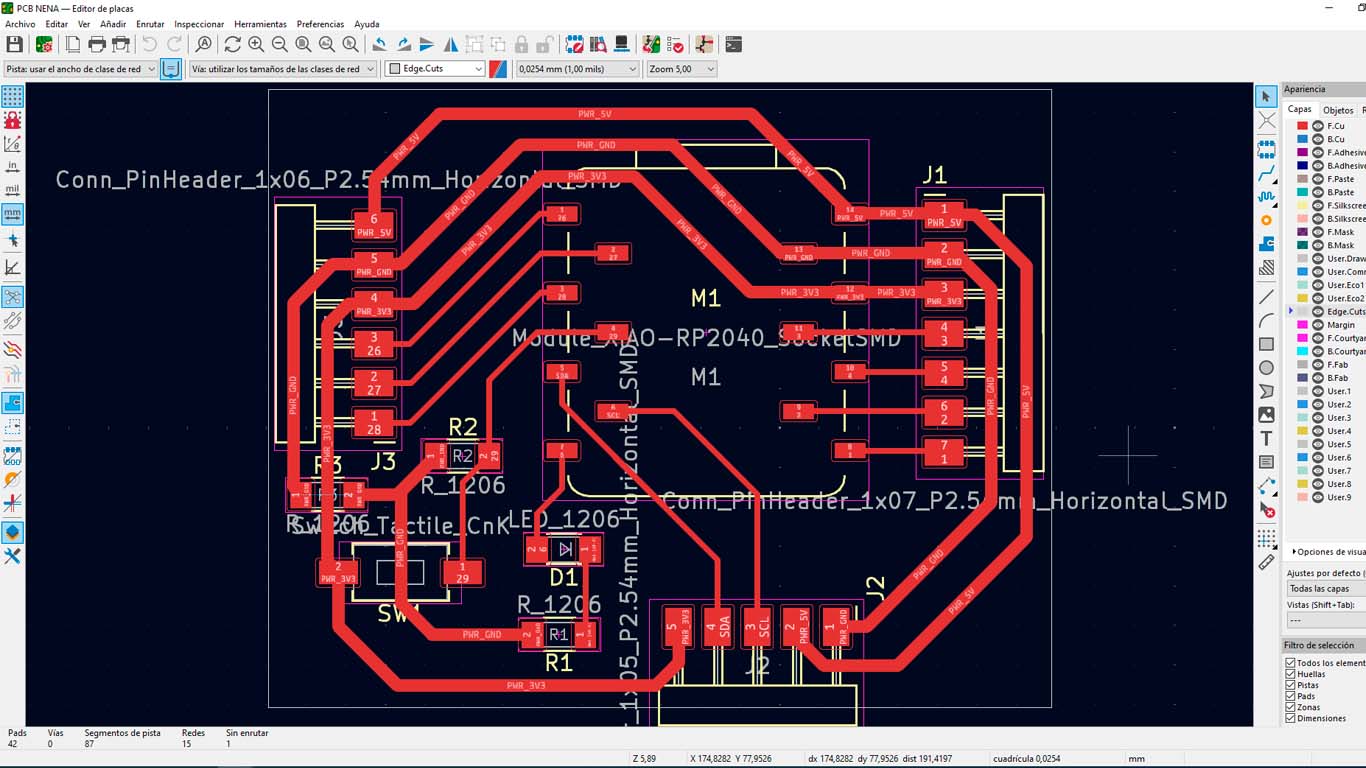
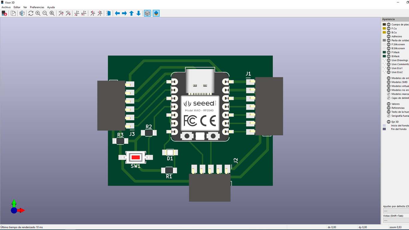
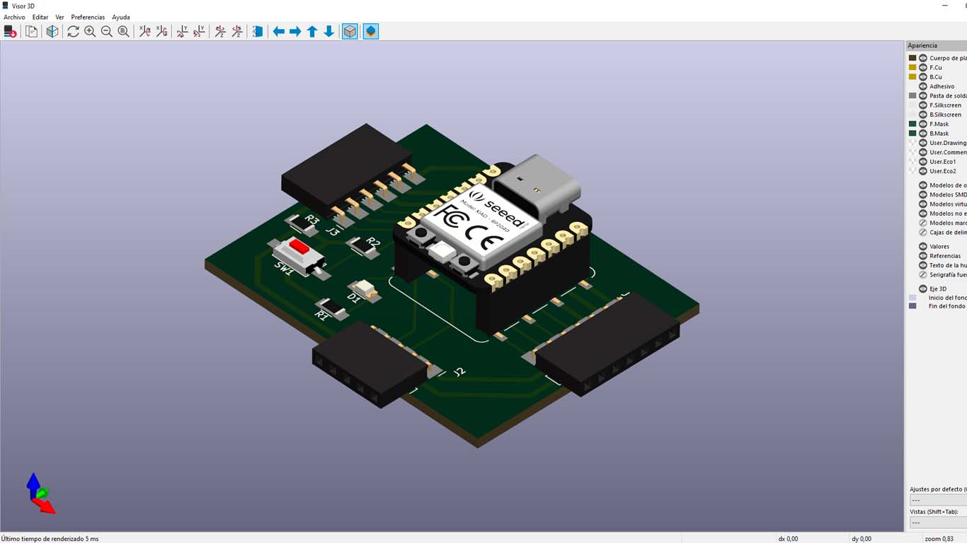
After moving on to the design of my board, we added 0.4mm and 0.8mm tracks, where as I said before, I prioritized operation over design, so I made a simple board in design and here is a screenshot of the design and the 3D.
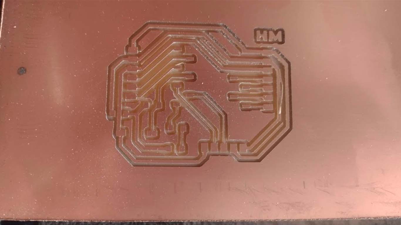
MILLING MY BOARD
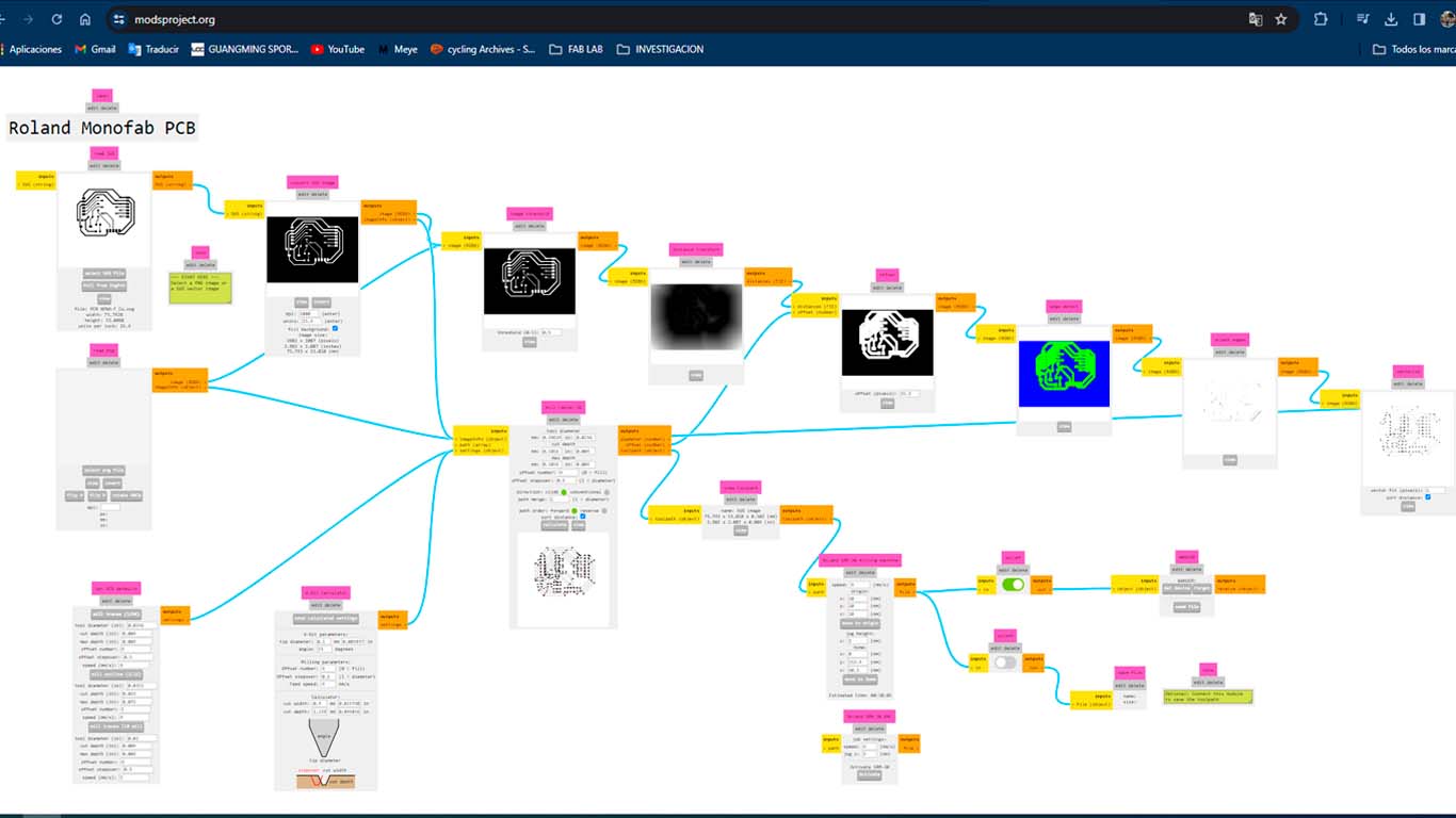
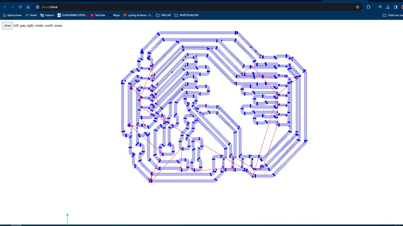
After obtaining the design, we go to MODS.CE to obtain the files to send for milling. Here the process in the MODS and also the milling process of the new plate.
COMPONENTS
Here is a list of the components that I am going to use on my development board.
| RESISTANCE: | 0; 499; 1K Ω |
|---|---|
| LED: | LED SMD RED |
| SWITCH: | SWITCH TACTILE |
| CONNECTOR: | 3 FEMALE CONNECTOR OF 7, 6 AND 5 PINS |
| MICROCONTROLLER: | XIAO RP2040 |
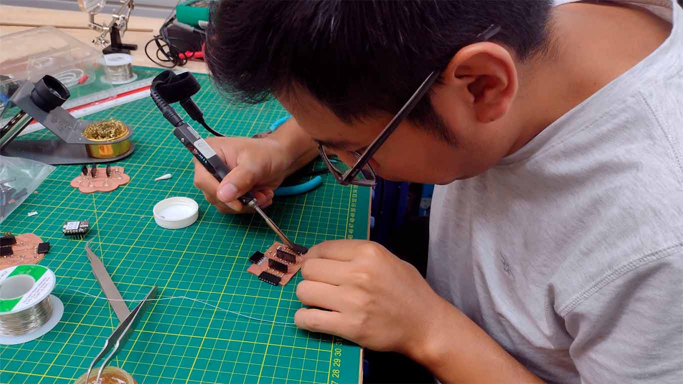
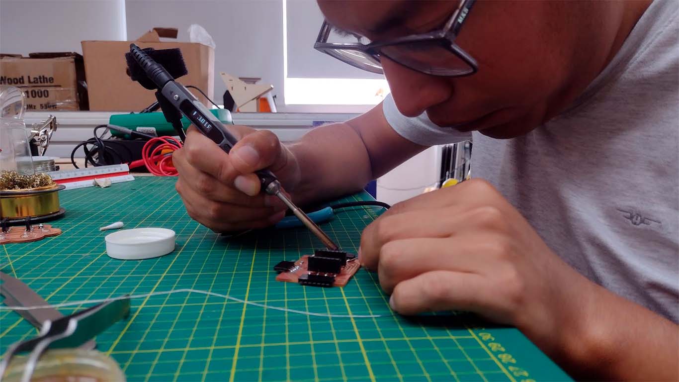
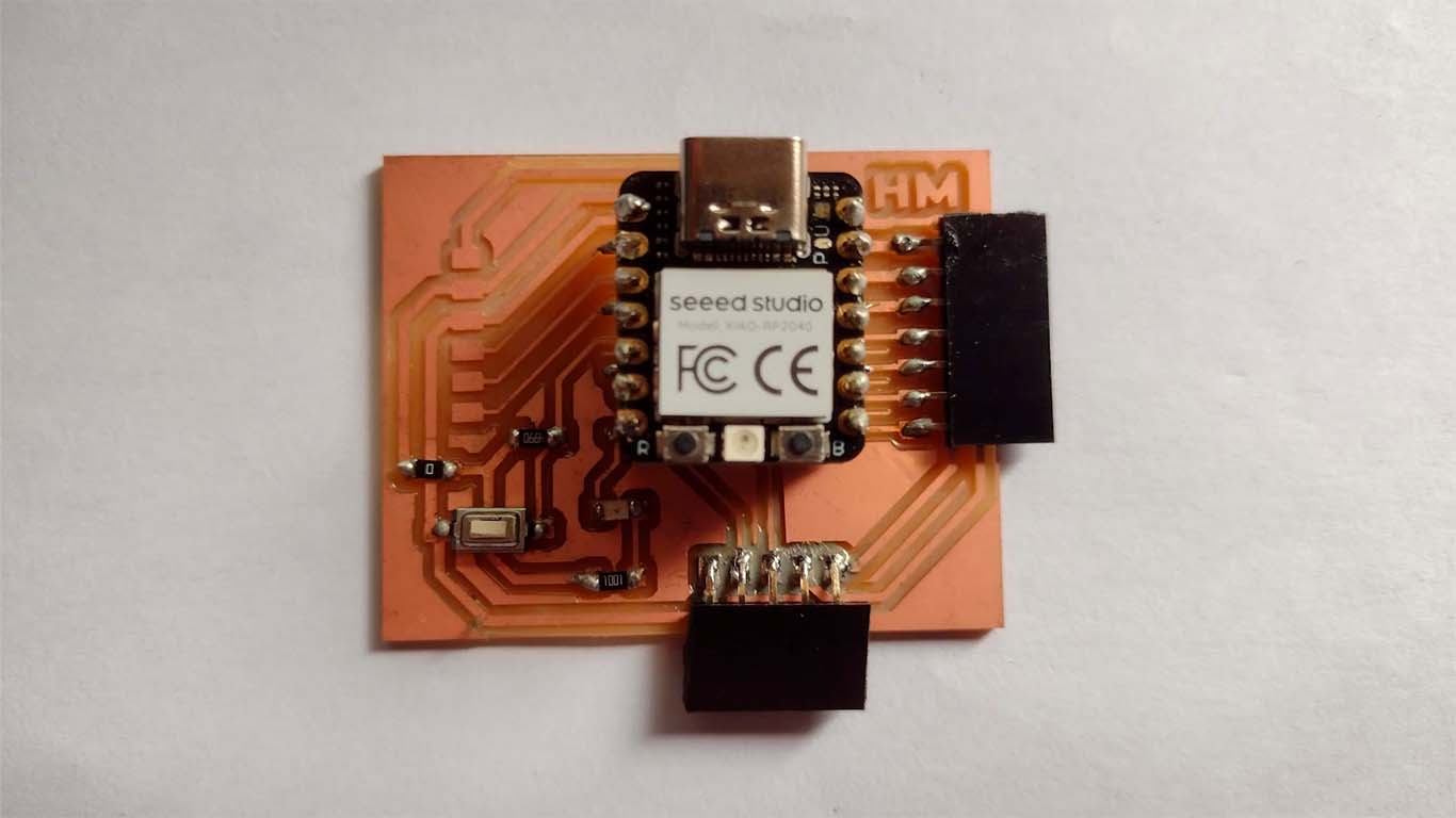
SOLDERING AND FINAL DEVELOPMENT BOARD
After milling my board, we moved on to the soldering process of the components that we are going to place on the board. Here is a photograph of my welding process and the final plate so I can move on to developing the assignment.
SERVOMOTOR
One of the outputs that I am going to use for my final project will be the SERVOMOTOR. Here I will show how I connected it, programmed it and how it works with my HM board.
OPERATING PRINCIPLE
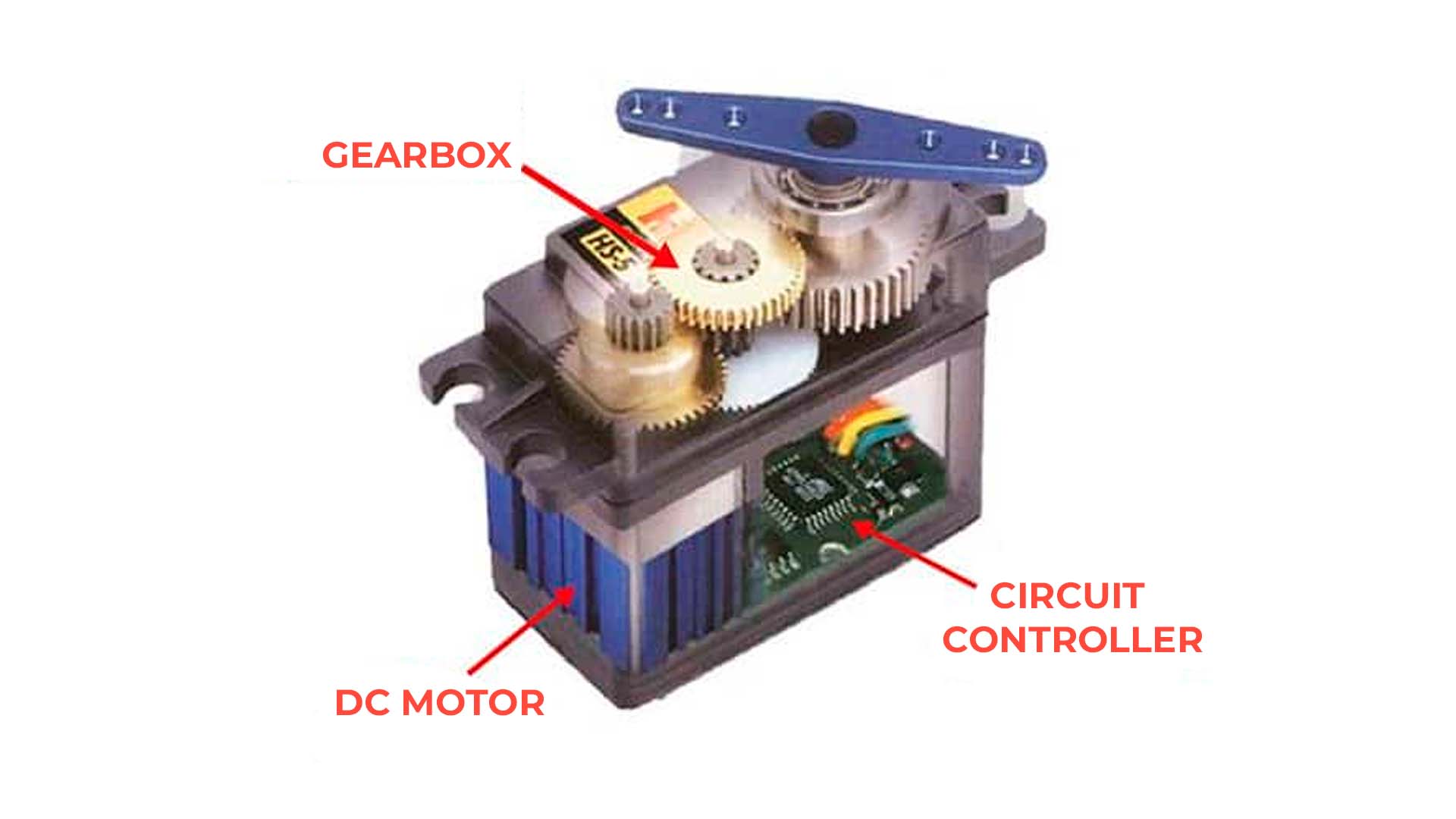
A servomotor is a rotary actuator that allows precise control of angular positions by changing its speed and acceleration. A servomotor is mainly composed of 4 parts:
- DC MOTOR (DIRECT CURRENT): Provides the power necessary to move the shaft.
- GEARBOX: Reduces engine speed and increases torque.
- POTENTIOMETER: Provides feedback on the current position of the axis.
- CIRCUIT CONTROLLER: Compares the control signal (desired position) with the current position (feedback from the potentiometer) and adjusts the motor to correct any errors.
HOW DOES IT WORK?
- The controller sends a control signal to the servo motor.
- The servomotor compares this signal with the signal from the potentiometer that measures the position of the shaft.
- If there is a difference between the desired position and the current position, the motor is activated to correct this difference.
- The process is repeated until the shaft reaches the desired position.
CONNECTION
The servomotor is made up of 3 connections: GND, power and signal PIN. In my case, I have an H KING servomotor, here are the connections according to the color of the cables.
- BROWN WIRE: Connect to GND (ground) of the microcontroller.
- RED WIRE: Connect to power supply (Vcc), usually 5V.
- ORANGE WIRE: Connect to a PWM (Pulse Width Modulated) signal pin of the microcontroller.
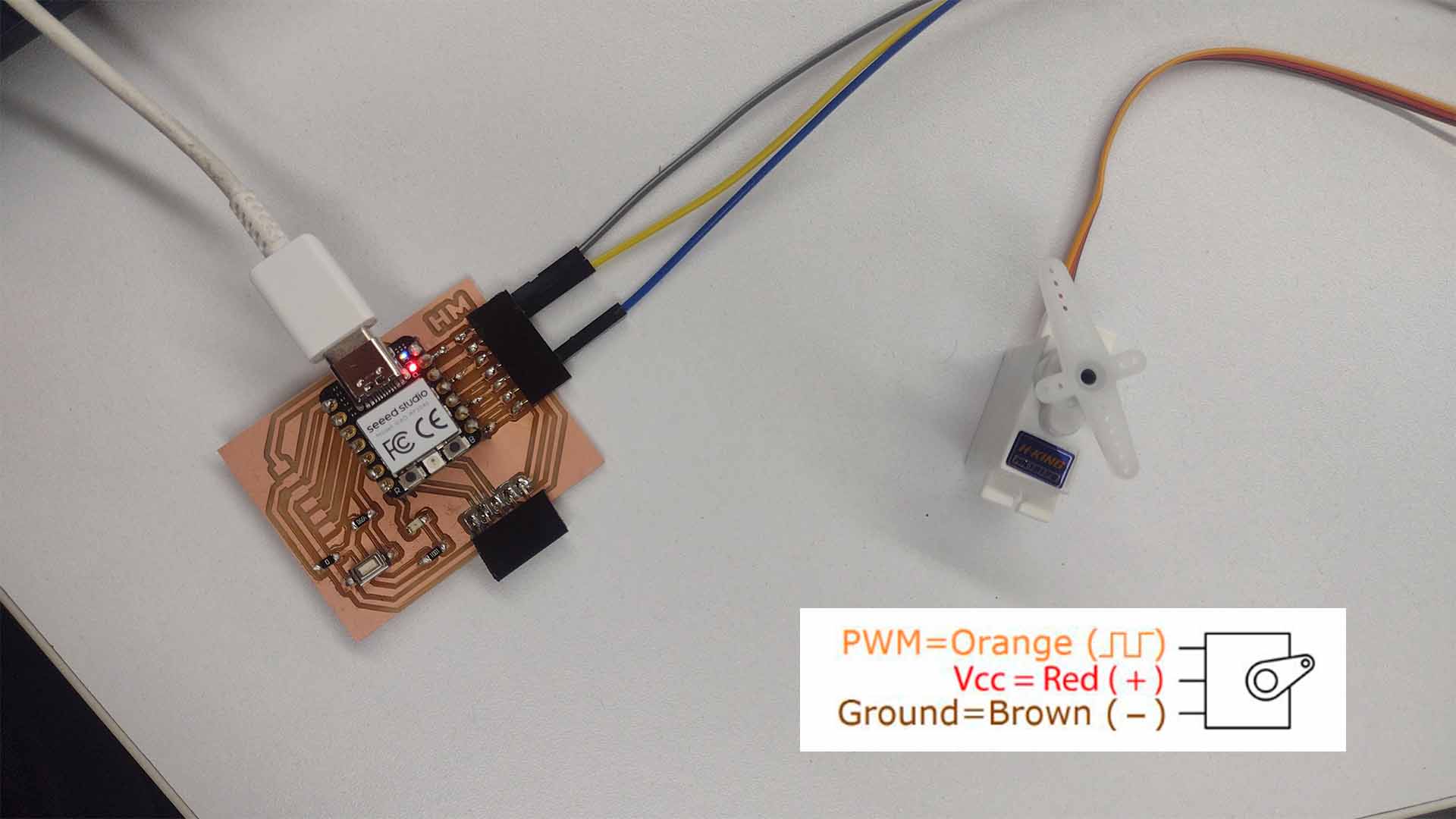
In the case of the servomotor, it has 3 cables, these are GND, 5V and PWM. So we need to connect them only to 3 points. In this case, we will connect it to pin 3 and the others to the corresponding pins of the XIAO RP2040.
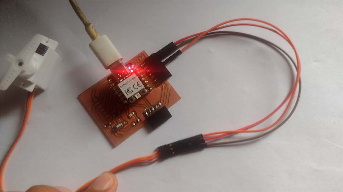
First we will connect the GND of the servo motor, which has the brown cable, to the GND of the XIAO RP2040.
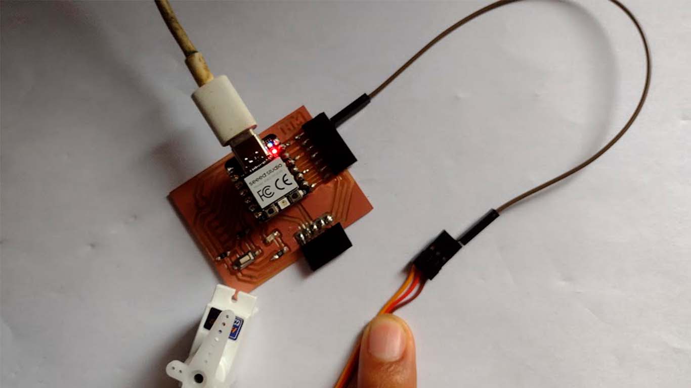
Secondly, we connect the red cable of the servo motor, which is 5V, to the pin where we find 5V on the XIAO RP2040. Here a photograph.
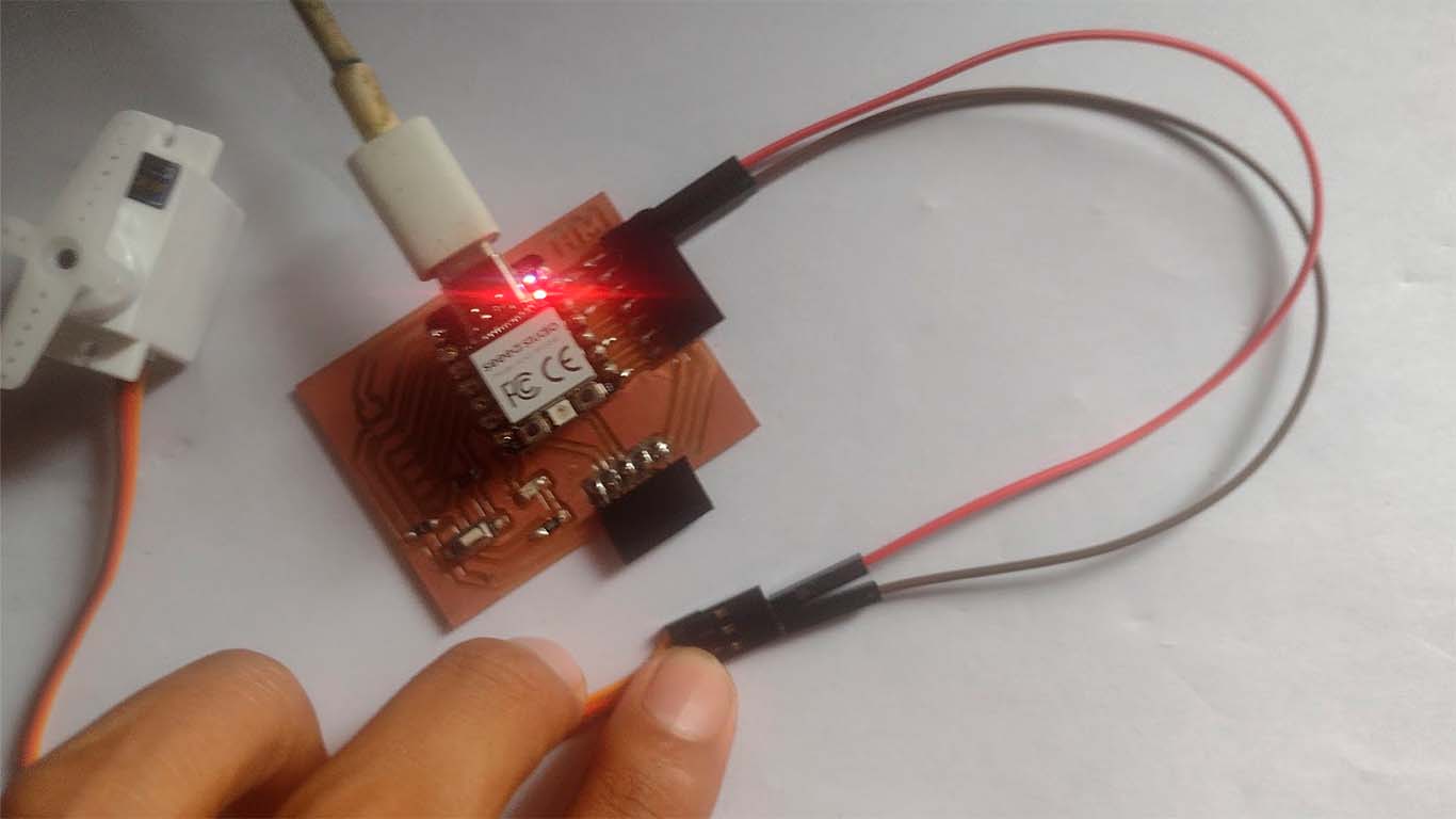
Finally, we connect the orange cable of the servomotor to any pin, in this case I chose number 3 of the XIAO RP2040. Here is a screenshot of the connection.
PROGRAMMING
Here I leave a programming that I do to ARDUINO IDE to be able to make the SERVOMOTOR work. Here I leave the code and a video of its operation.
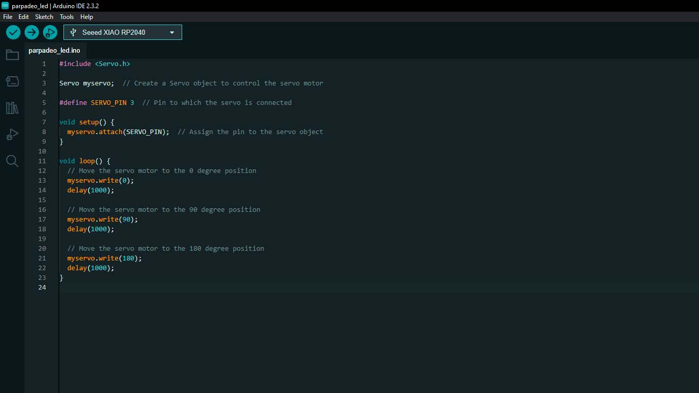
                                #include Servo.h

                                    Servo myservo;  // Create a Servo object to control the servo motor

                                    #define SERVO_PIN 3  // Pin to which the servo is connected

                                    void setup() {
                                      myservo.attach(SERVO_PIN);  // Assign the pin to the servo object
                                    }

                                    void loop() {
                                      // Move the servo motor to the 0 degree position
                                      myservo.write(0);
                                      delay(1000);

                                      // Move the servo motor to the 90 degree position
                                      myservo.write(90);
                                      delay(1000);

                                      // Move the servo motor to the 180 degree position
                                      myservo.write(180);
                                      delay(1000);
                                    }
OLED DISPLAY I2C
Another output that I wanted to know how to program was the OLED since I did not have the opportunity in previous weeks to program it. Until this week I was intrigued to know what it is like to program it and see it work. Therefore, here I leave you the process of connecting and programming the output.
OPERATING PRINCIPLE
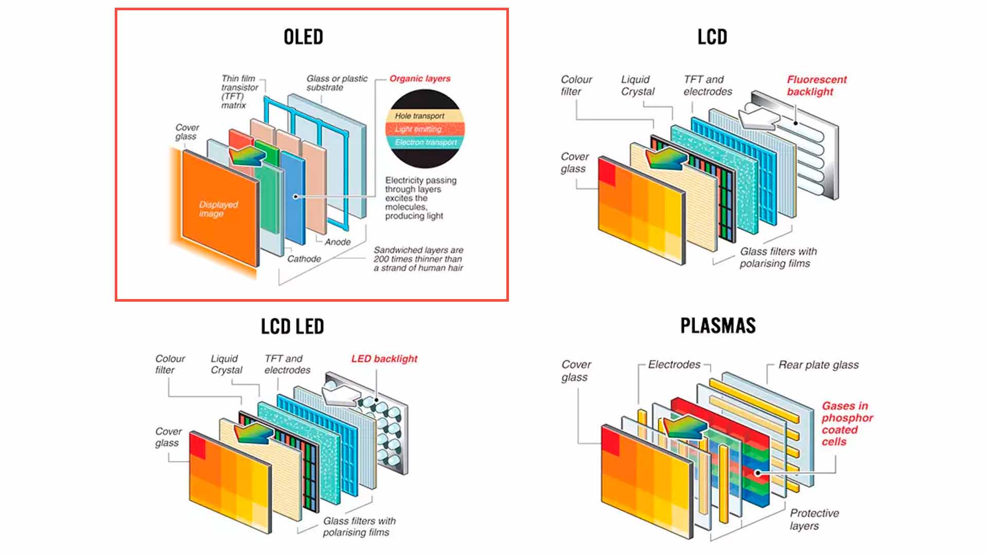
OLED DISPLAY is a display that uses organic light-emitting diodes to create images. Unlike LCD displays, OLEDs do not require backlighting, allowing for richer colors and deeper blacks. OLEDs are energy efficient and can be extremely thin and flexible.
I2C is a serial communication protocol that allows the connection of multiple devices through two cables: one for the data signal (SDA) and another for the clock signal (SCL). This protocol is commonly used due to its simplicity and efficiency.
OLED displays offer richer colors, better viewing angles and deeper blacks compared to LCD and plasma, which rely on backlighting and are less energy efficient. OLED is superior due to its image quality and energy efficiency.
HOW DOES IT WORK?
- PIXEL POWER: Each pixel in an OLED is a diode that emits light when a current passes through it.
- PIXEL LEVEL CONTROL: The light intensity of each pixel can be controlled by varying the amount of current.
- I2C INTERFACE: The display receives commands and data through the I2C interface. The microcontroller sends instructions to the OLED display to turn on, turn off, or adjust the brightness of individual pixels.
CONNECTION
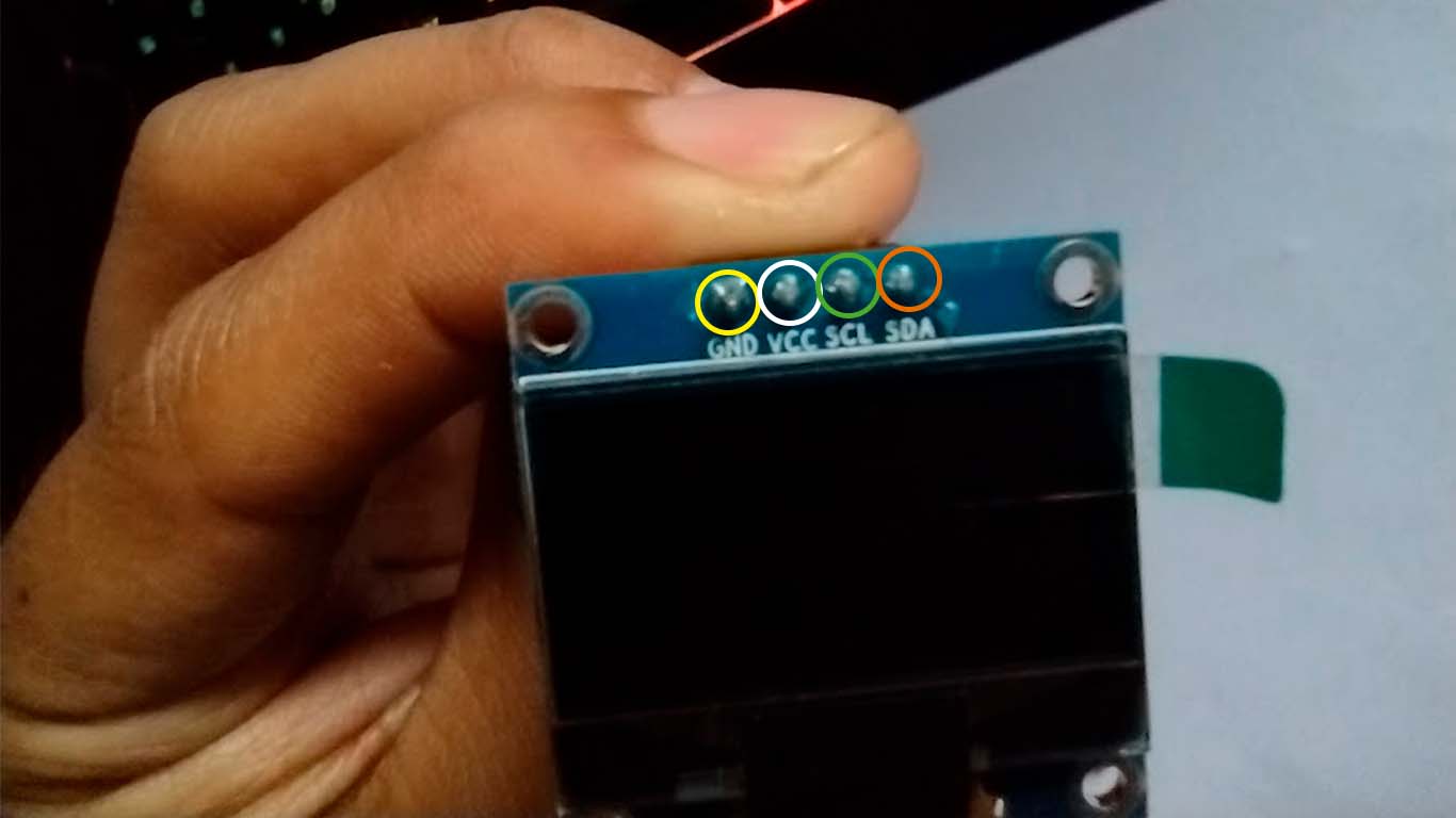
The OLED DISPLAY I2C connection is made up of 4 main pins that it needs for its operation:
- PIN GND: Connect to GND (ground) of the microcontroller.
- PIN VCC: Connect to power supply, usually 3.3V or 5V.
- PIN SCL: Connect to the I2C clock pin of the microcontroller (PIN 7 on Xiao RP2040).
- PIN SDA: Connect to the I2C data pin of the microcontroller (PIN 6 on Xiao RP2040).
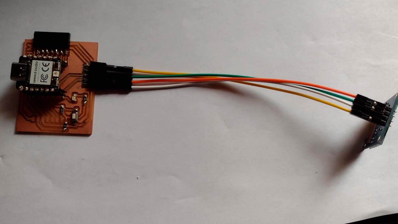
First connect GND to the GND of our board. In my case I have the yellow cable as it is in the photo.
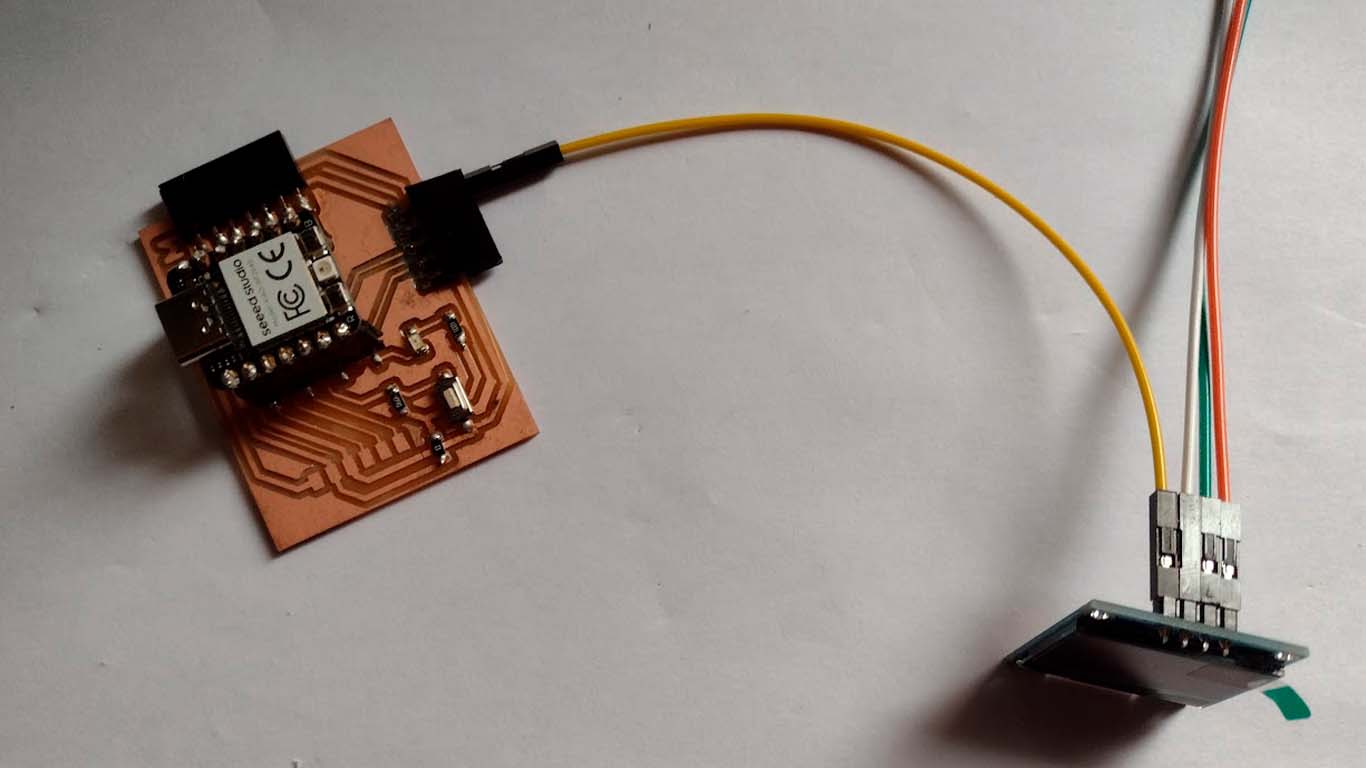
We continue with the VCC connection, which in my case I connected to the 3.3V pin of my board and the XIAO RP2040. Here we must take into account that some OLEDs ask for 5V, we have to find out before.
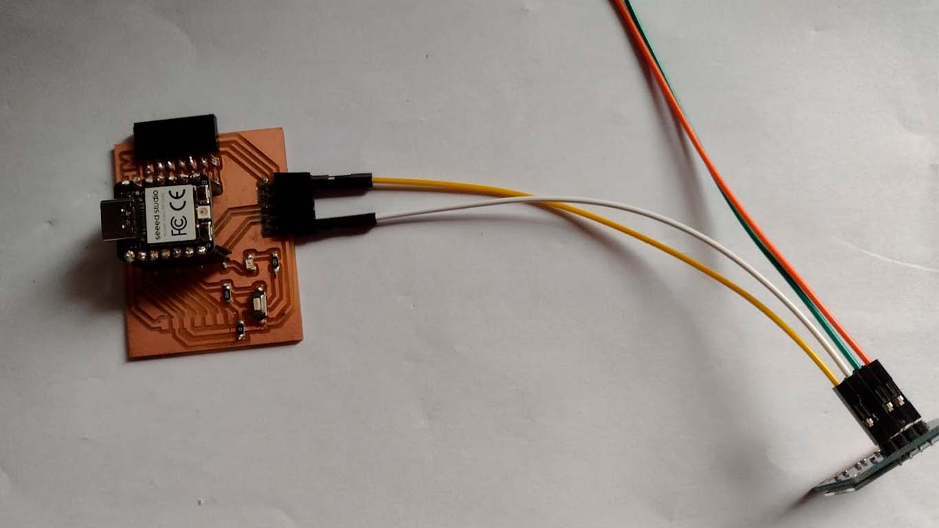
Then we connect the SDA pin of the OLED to pin 6 or D4 of the XIAO RP2040. Here we have to take into account that our board must already be designed for this output since it is important to make the design to receive this output.
Finally, we connect the SCL pin to pin 7 or D5 of the XIAO RP2040. Here, like the previous pin, we have to design the board to receive this type of I2C connection. Here is a photograph of it.
PROGRAMMING
For programming I wanted to make a presentation of myself and have it shown on the OLED. Here is an example that I was able to obtain programming in the Arduino IDE.
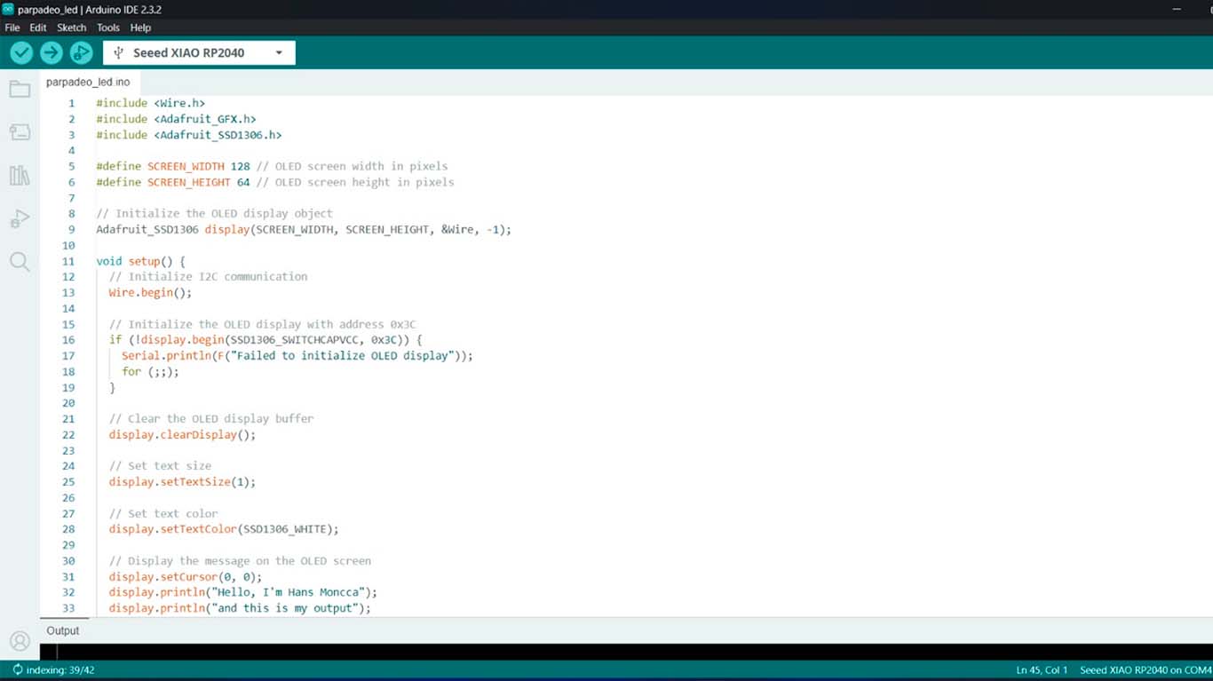
                                #include Wire.h
                                    #include Adafruit_GFX.h
                                    #include Adafruit_SSD1306.h

                                    #define SCREEN_WIDTH 128 // OLED screen width in pixels
                                    #define SCREEN_HEIGHT 64 // OLED screen height in pixels

                                    // Initialize the OLED display object
                                    Adafruit_SSD1306 display(SCREEN_WIDTH, SCREEN_HEIGHT, &Wire, -1);

                                    void setup() {
                                      // Initialize I2C communication
                                      Wire.begin();

                                      // Initialize the OLED display with address 0x3C
                                      if (!display.begin(SSD1306_SWITCHCAPVCC, 0x3C)) {
                                        Serial.println(F("Failed to initialize OLED display"));
                                        for (;;);
                                      }

                                      // Clear the OLED display buffer
                                      display.clearDisplay();

                                      // Set text size
                                      display.setTextSize(1);

                                      // Set text color
                                      display.setTextColor(SSD1306_WHITE);

                                      // Display the message on the OLED screen
                                      display.setCursor(0, 0);
                                      display.println("Hello, I'm Hans Moncca");
                                      display.println("and this is my output");
                                      display.println("schedule for week 9 of");
                                      display.println("the FAB ACADEMY.");
                                      display.println("Greetings to all");
                                      display.println("FAB LAB USCUR");
                                      display.display();
                                    }

                                    void loop() {
                                      // Nothing more to do here, the message will be displayed only once at startup
                                      delay(10000); // Wait 10 seconds before restarting (optional)
                                    }
NEOPIXEL WS2812B
Finally, we will connect and program a NEOPIXEL. I will also use this output for my final project, so happily I was able to understand how it works and what I should take into account for its programming.
OPERATING PRINCIPLE
NEOPIXEL is a brand of addressable RGB LEDs produced by Adafruit. Each LED contains a microcontroller that allows individual control of its color and brightness. NeoPixels are known for their ease of use and flexibility, and are used in a variety of lighting and visual effects projects.
Each NeoPixel LED can emit a wide range of colors combining different intensities of red, green and blue (RGB). These LEDs are series addressable, meaning that multiple LEDs can be controlled via a single data line.
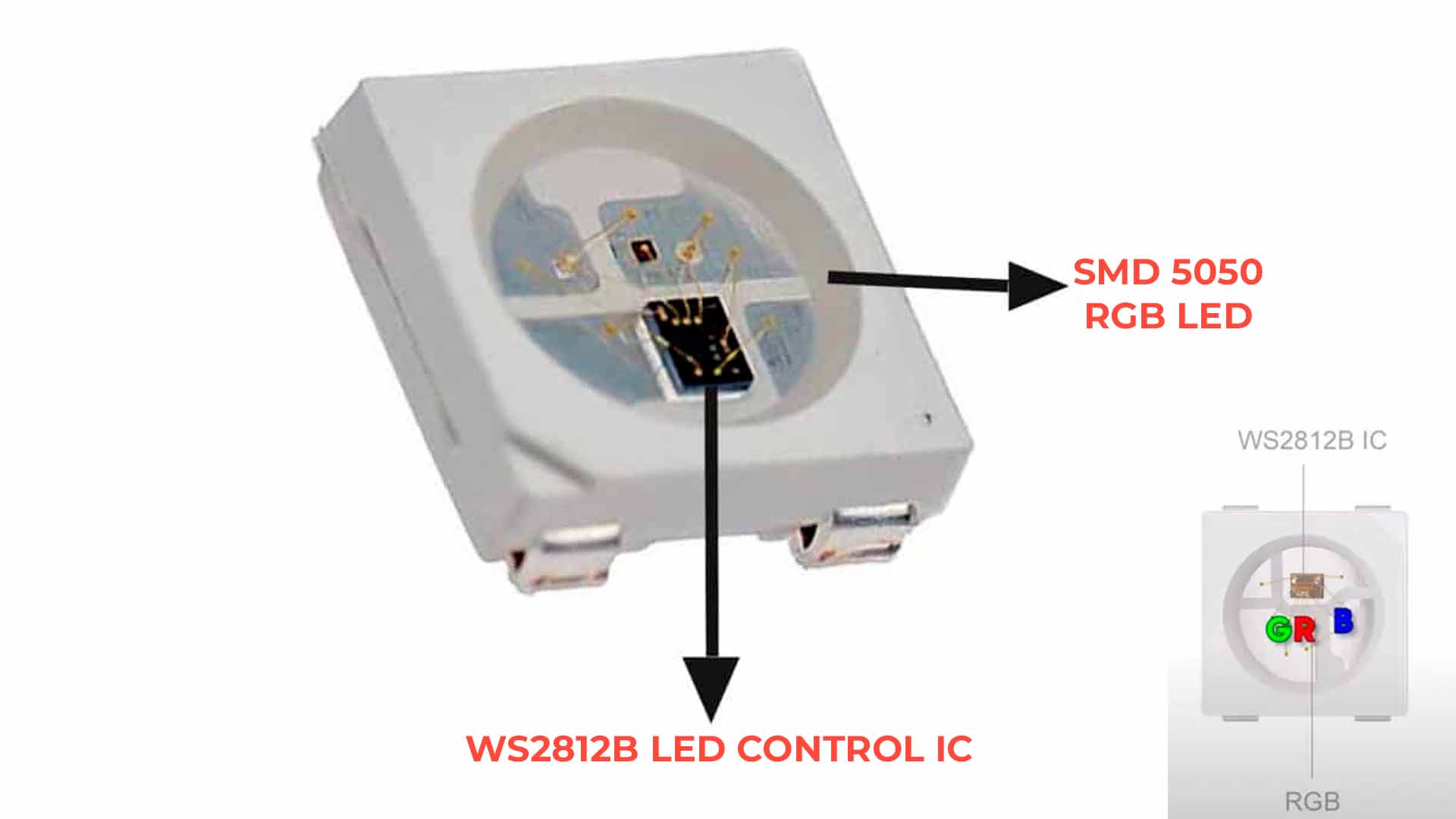
HOW DOES IT WORK?
- INTEGRATED MICROCONTROLLER Each NeoPixel has a microcontroller that interprets the data signals and adjusts the color and brightness of the corresponding LED.
- COMMUNICATION PROTOCOL: They use a communication protocol based on a single data line that transmits information serially. The NeoPixel's microcontroller decodes this information and adjusts the LEDs accordingly.
- LED STRING: NeoPixels can be chained one after another. The first LED receives the data signal, adjusts its color and brightness, and passes the rest of the signal to the next LED in the chain.
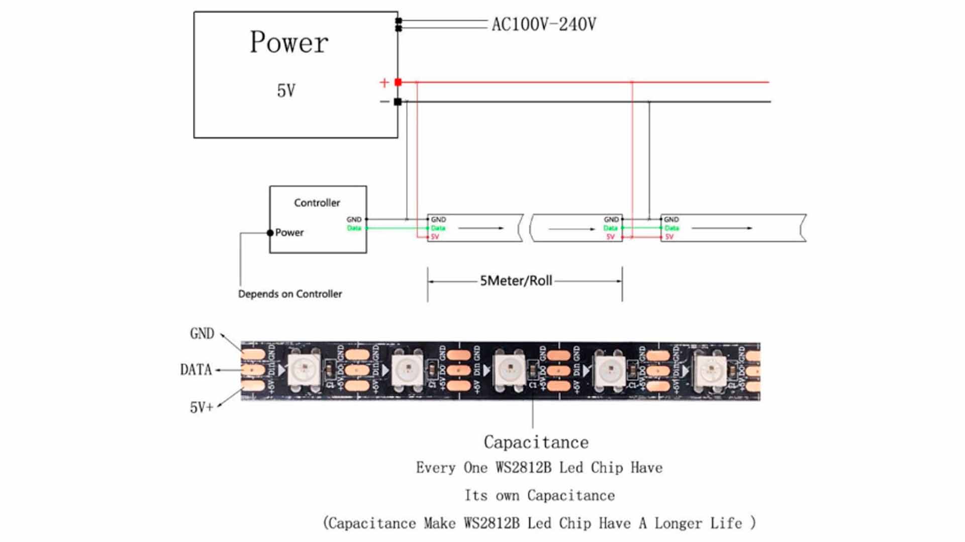
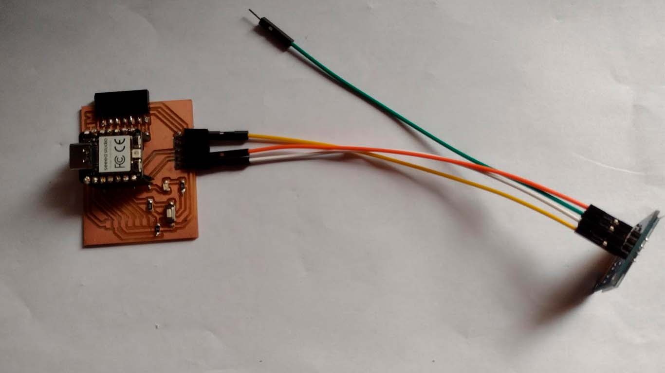
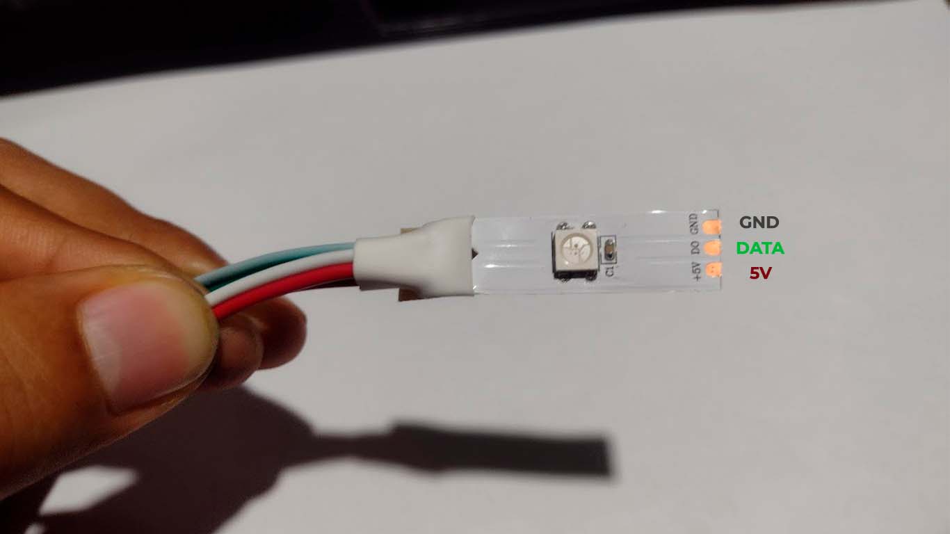
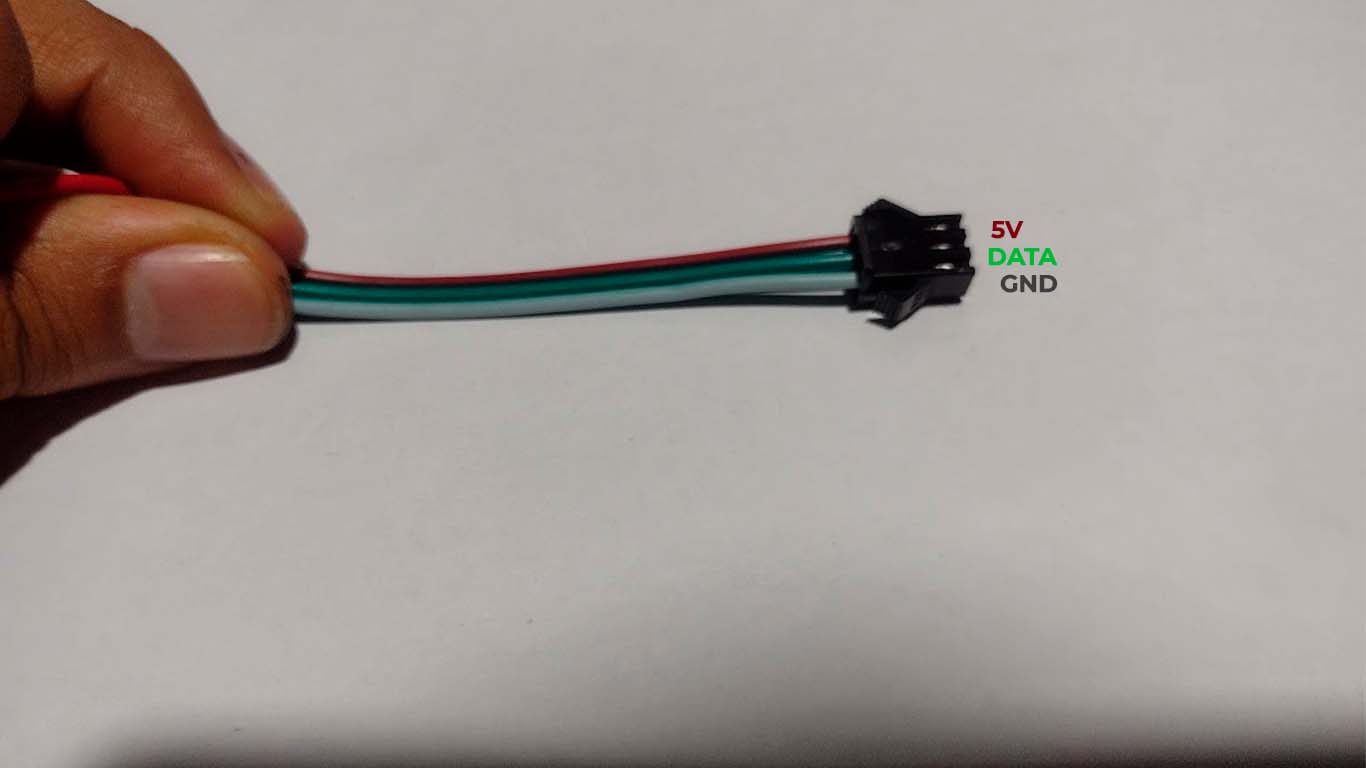
CONNECTION
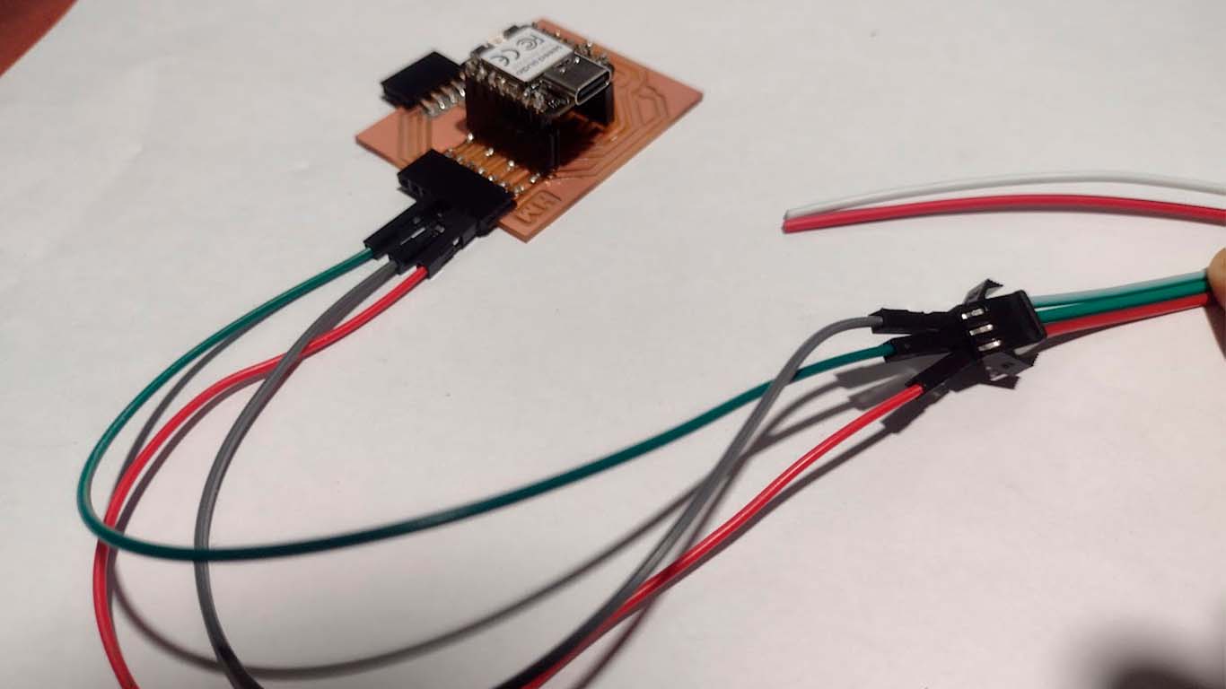
To connect the NEOPIXEL we first have to understand how it is connected. In my case, the neopixel has a GND, DATA and finally 5V pin that will be connected to the appropriate tracks on our board.
First we will connect the 5V of the neopixel to the pin where we have this voltage on our board. Here is an example on my plate.
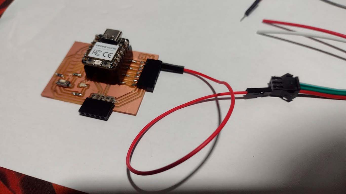
Next, we will connect GND where we have the GND pin on our board. Here we have to be careful with the connections and know our board.
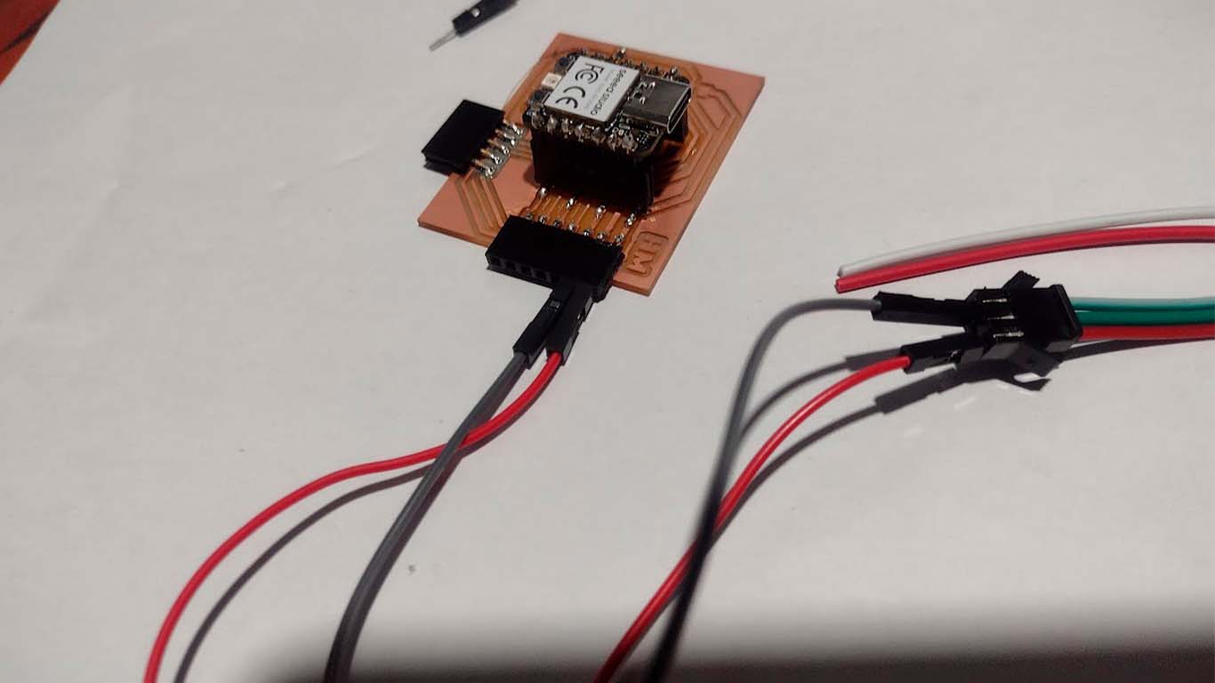
Finally, we will connect the DATA pin of the neopixel to a pin on our XIAO RP2040. In this case I will connect it to pin 3 that I have on one of my connectors on the board.
PROGRAMMING
To program my NEOPIXEL we carried out a simple test to see how it works. With the help of CHATGPT, here is the code I used to program it in the Arduino IDE.
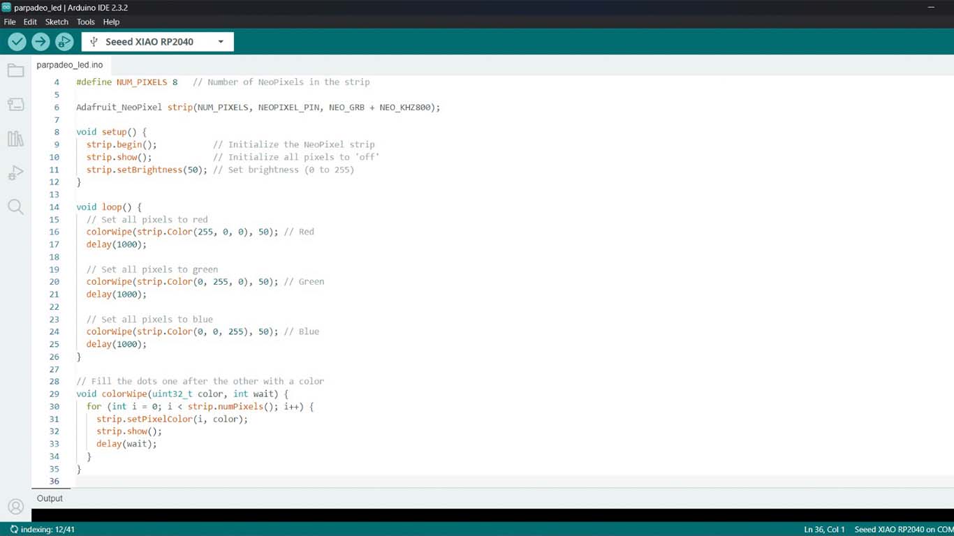
                                #include Adafruit_NeoPixel.h

                                    #define NEOPIXEL_PIN 3 // Pin to which the NeoPixel strip is connected
                                    #define NUM_PIXELS 8   // Number of NeoPixels in the strip

                                    Adafruit_NeoPixel strip(NUM_PIXELS, NEOPIXEL_PIN, NEO_GRB + NEO_KHZ800);

                                    void setup() {
                                      strip.begin();           // Initialize the NeoPixel strip
                                      strip.show();            // Initialize all pixels to 'off'
                                      strip.setBrightness(50); // Set brightness (0 to 255)
                                    }

                                    void loop() {
                                      // Set all pixels to red
                                      colorWipe(strip.Color(255, 0, 0), 50); // Red
                                      delay(1000);

                                      // Set all pixels to green
                                      colorWipe(strip.Color(0, 255, 0), 50); // Green
                                      delay(1000);

                                      // Set all pixels to blue
                                      colorWipe(strip.Color(0, 0, 255), 50); // Blue
                                      delay(1000);
                                    }

                                    // Fill the dots one after the other with a color
                                    void colorWipe(uint32_t color, int wait) {
                                      for (int i = 0; i < strip.numPixels(); i++) {
                                        strip.setPixelColor(i, color);
                                        strip.show();
                                        delay(wait);
                                      }
                                    }
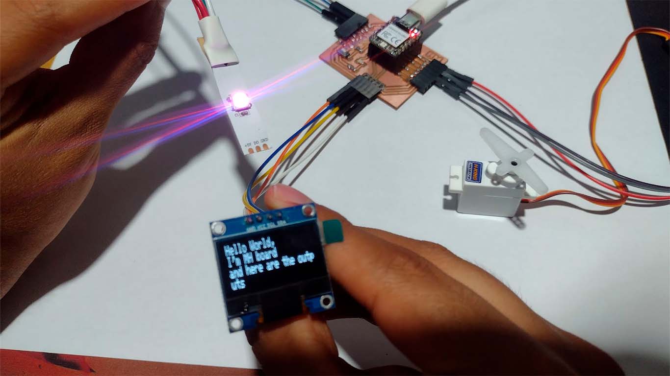
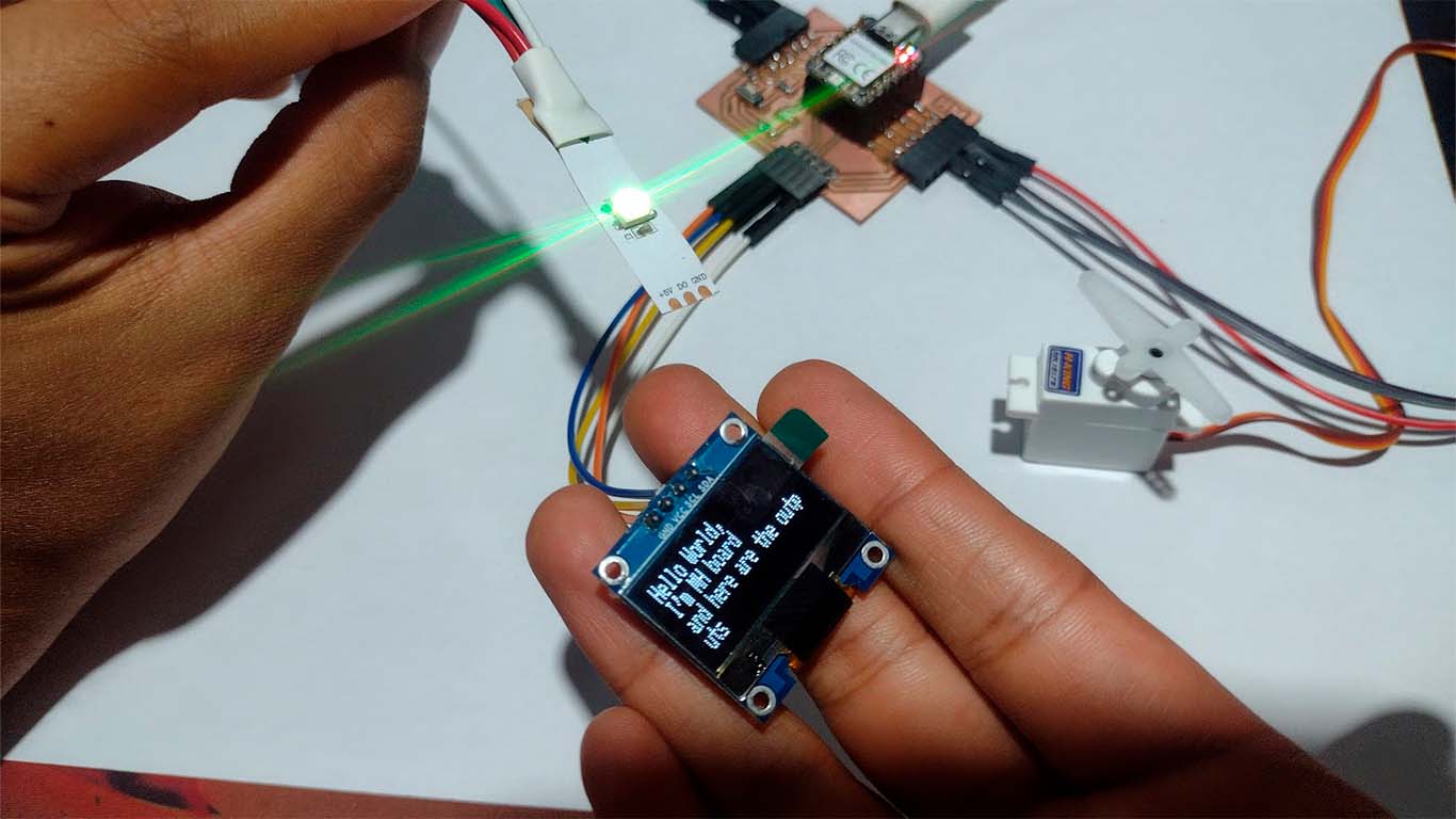
OUTPUTS TOGETHER
To finish the assignment I wanted to test all the outputs together to see if they could work like this. I connected each output to different pins of the XIAO RP2040 and I could see that they do work, although I think it requires a little more energy to work, but I could see that they do perform their respective functions. Here are some photographs and its programming.
PROGRAMMING
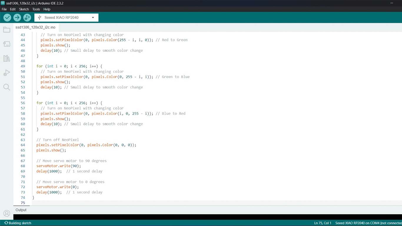
For programming I asked CHATGPT for support to help me distribute and program each output to be able to run all 3 at the same time. Here I leave the code and a video of how the outputs worked.
                                #include Adafruit_GFX.h>
                                #include Adafruit_SSD1306.h>
                                #include Adafruit_NeoPixel.h>
                                #include Servo.h>

                                    #define OLED_RESET    -1
                                    Adafruit_SSD1306 display(OLED_RESET);

                                    #define NEOPIXEL_PIN 26
                                    #define NUMPIXELS    1
                                    Adafruit_NeoPixel pixels(NUMPIXELS, NEOPIXEL_PIN, NEO_GRB + NEO_KHZ800);

                                    Servo servoMotor; // Servo motor object

                                    void setup() {
                                      // Initialize OLED display
                                      display.begin(SSD1306_SWITCHCAPVCC, 0x3C);
                                      display.display();
                                      delay(2000);  // 2 seconds delay

                                      // Initialize NeoPixel
                                      pixels.begin();
                                      pixels.setBrightness(50);  // Set NeoPixel brightness (0-255)

                                      // Initialize servo motor
                                      servoMotor.attach(3); // Servo motor is connected to pin 3
                                    }

                                    void loop() {
                                      // Display message on OLED display
                                      display.clearDisplay();
                                      display.setTextSize(1);
                                      display.setTextColor(SSD1306_WHITE);
                                      display.setCursor(0,0);
                                      display.println("Hello World,");
                                      display.println("I'm ChatGPT");
                                      display.println("and here are the outputs");
                                      display.println("I can control!");
                                      display.display();

                                      // NeoPixel color sequence
                                      for (int i = 0; i < 256; i++) {
                                        // Turn on NeoPixel with changing color
                                        pixels.setPixelColor(0, pixels.Color(255 - i, i, 0)); // Red to Green
                                        pixels.show();
                                        delay(10); // Small delay to smooth color change
                                      }

                                      for (int i = 0; i < 256; i++) {
                                        // Turn on NeoPixel with changing color
                                        pixels.setPixelColor(0, pixels.Color(0, 255 - i, i)); // Green to Blue
                                        pixels.show();
                                        delay(10); // Small delay to smooth color change
                                      }

                                      for (int i = 0; i < 256; i++) {
                                        // Turn on NeoPixel with changing color
                                        pixels.setPixelColor(0, pixels.Color(i, 0, 255 - i)); // Blue to Red
                                        pixels.show();
                                        delay(10); // Small delay to smooth color change
                                      }

                                      // Turn off NeoPixel
                                      pixels.setPixelColor(0, pixels.Color(0, 0, 0));
                                      pixels.show();

                                      // Move servo motor to 90 degrees
                                      servoMotor.write(90);
                                      delay(1000);  // 1 second delay

                                      // Move servo motor to 0 degrees
                                      servoMotor.write(0);
                                      delay(1000);  // 1 second delay
                                    }
REVIEW OF THE CLASS
During the review of this class I volunteered in the minute 1:18:00
Clic here to 20240327 review from Academany on Vimeo.
FILES
Here you can download all the files that I have made for the following assignment: