Output Devices
Week 9
Group assignment:
- Measure the power consumption of an output device
Group 1
Group 2
Group 3
Group 1:
- Hans Moncca
- Maryori Vasquez
- Maria Angela Mejia
- Cristian Loayza
- Silvana Espinoza

MEASURING CONSUMPTION POWER
For group development we decided to measure the outputs of each one with their own boards developed last week. The idea was to learn how to measure AMPS, VOLTS and replicate it on each board. In my case, I used the SERVO MOTOR, OLED SCREEN and NEOPIXEL LED. To carry out the OUTPUTS DEVICE week, I decided to make a new board solving the errors that I had in the last week, I did not focus much on the design but more on the operation to be able to develop the individual and group assignment. Then I modified and redesigned the plate, here is my group order.
SERVO MOTOR - VOLTAGE
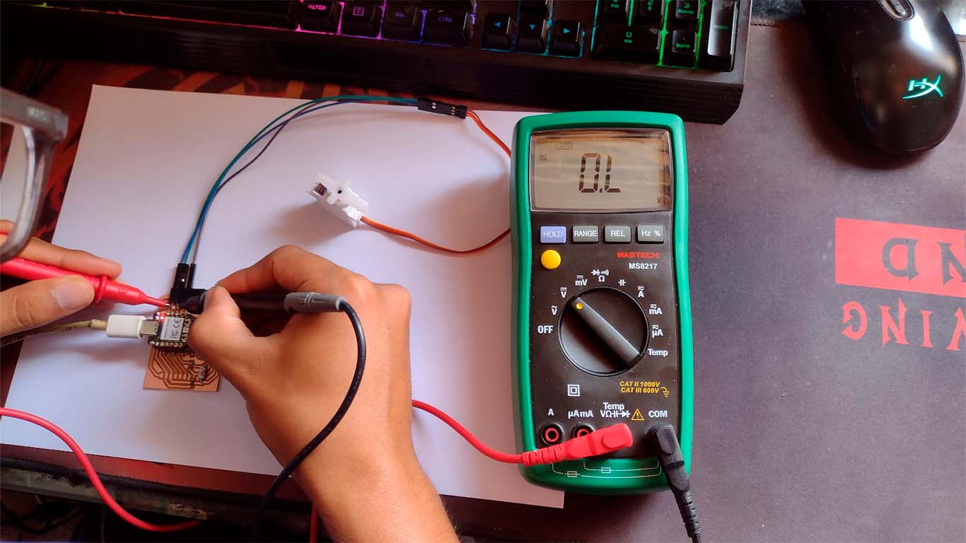
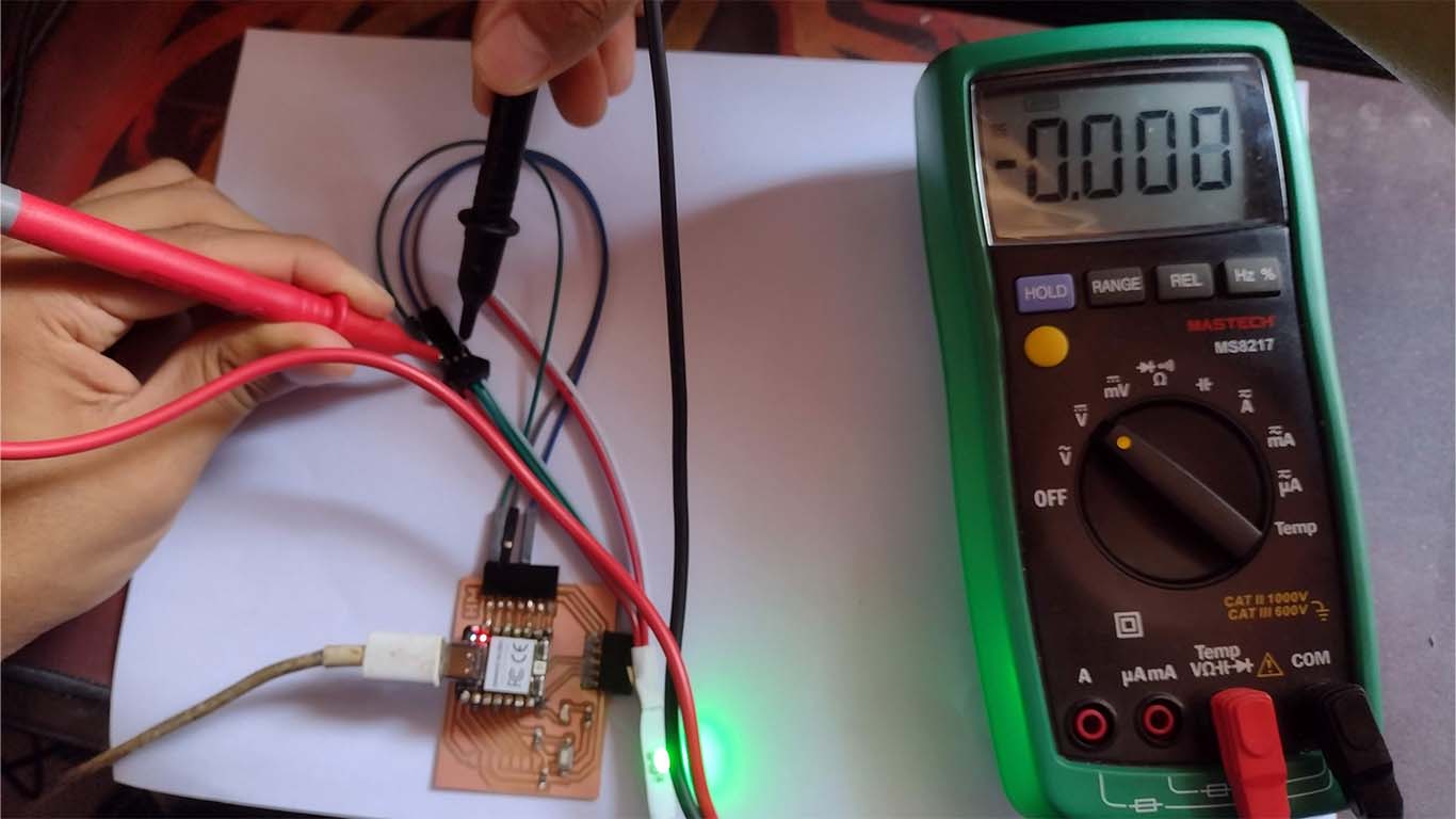
To measure the power consumption, I first use the multimeter and also the oscilloscope Here my analysis of the servomotor: First we measure the VOLTAGE that the SERVOMOTOR needs for its operation, to do this we place the COM of the multimeter in the GND of the SERVOMOTOR and the POSITIVE in the 5V of the MOTOR. This will give us a measurement of 4.65 to 4.68 of the voltage that the SERVOMOTOR needs to operate. Here are some images of how we measure it.

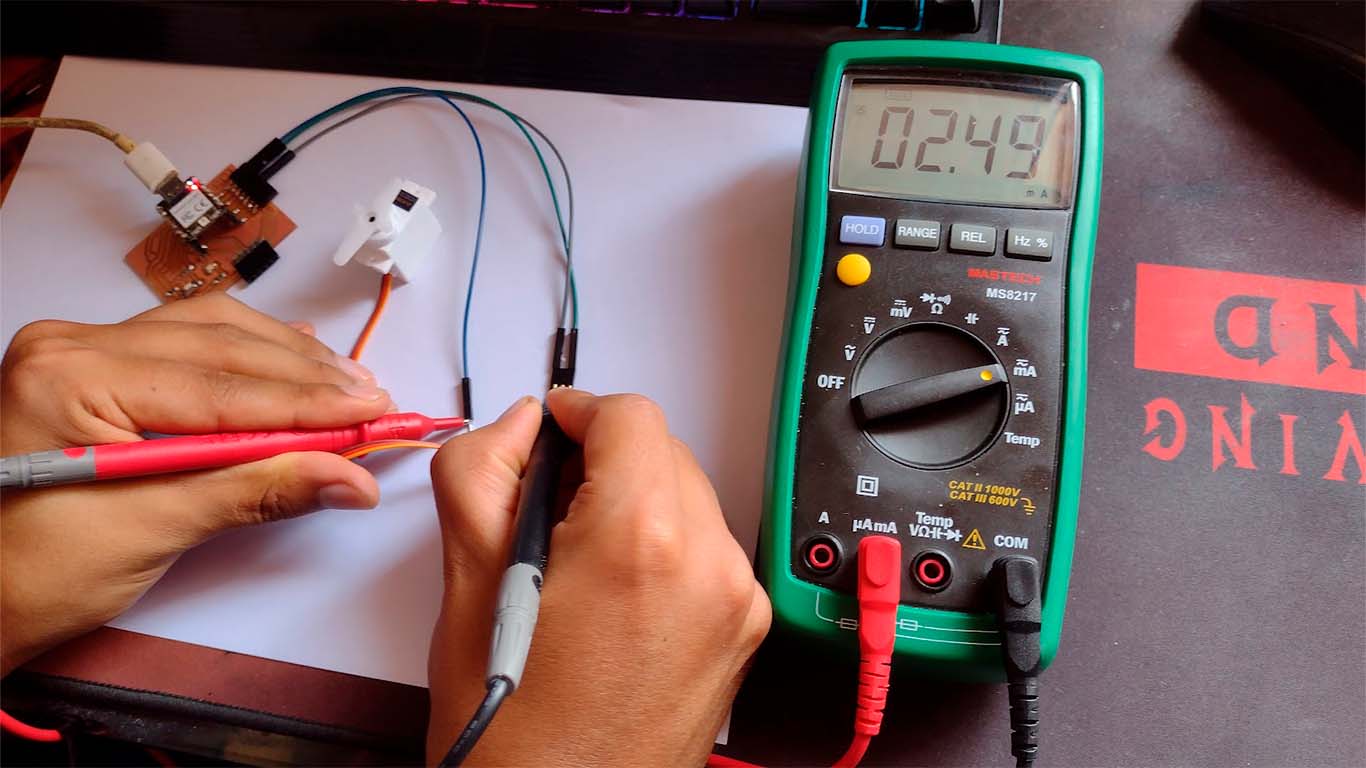
SERVO MOTOR - AMPS


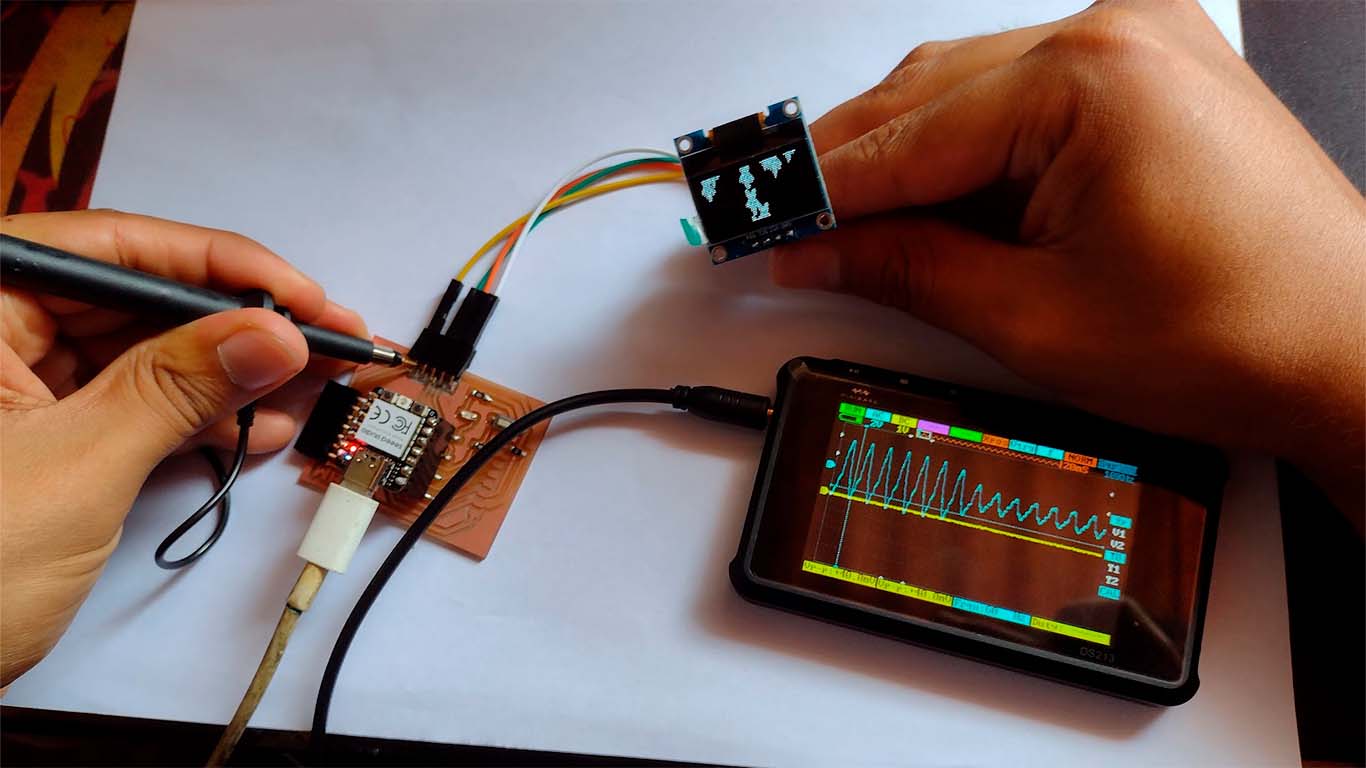
SERVO MOTOR - OSCILLOSCOPE
We also analyzed with the oscilloscope where we obtained a WAVE type diagram when we connected the oscilloscope channel to the GND pin of the board. We could see that it was constant, here are some photographs of the measurement.
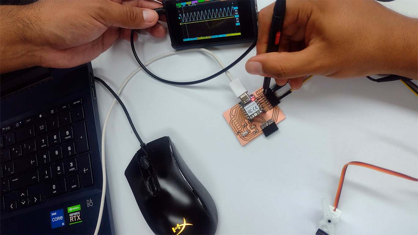
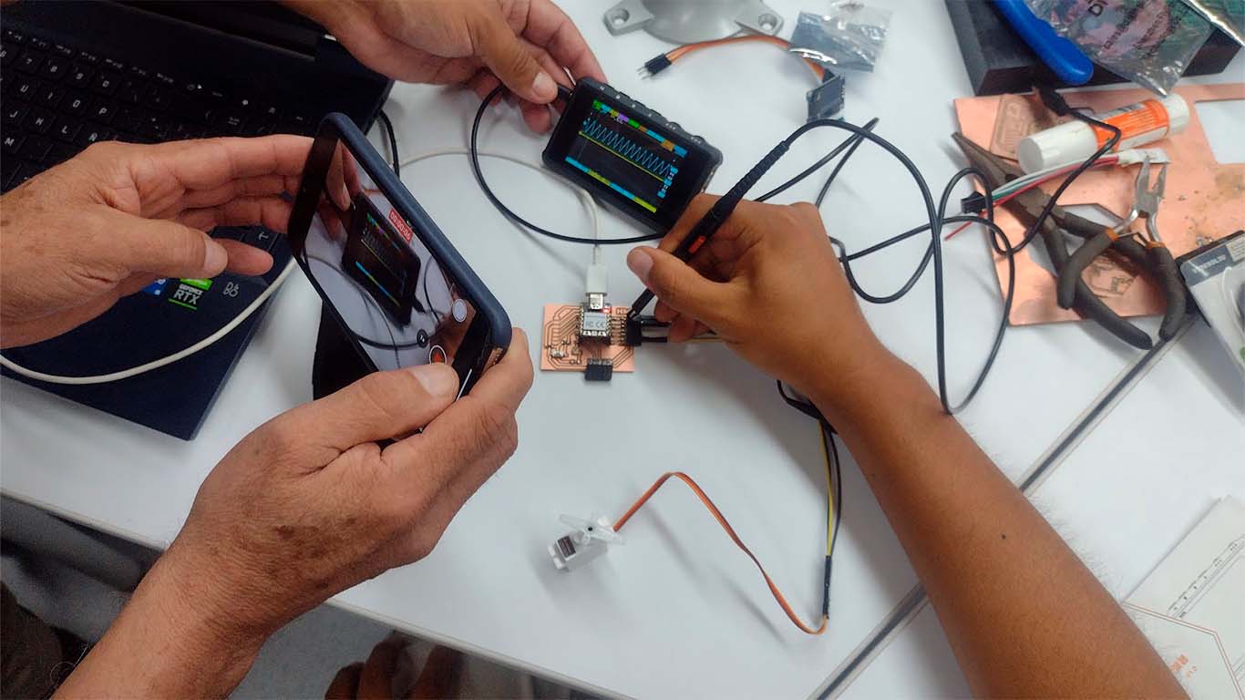
By measuring with the oscilloscope we observe the difference that the waves have with other types. In the following video, we can see the behavior of the OSCILLOSCOPE when we contact the GND and see the data it provides us.

OLED DISPLAY - VOLTAGE


OLED DISPLAY - OSCILLOSCOPE
Now we will use the oscilloscope for the OLED. In this case, we did the tests on each pin that the OLED has and it gave us the same wave signal in each of them, it only changed the intensity and we managed to capture some of them. Here are some photographs of how we did it.

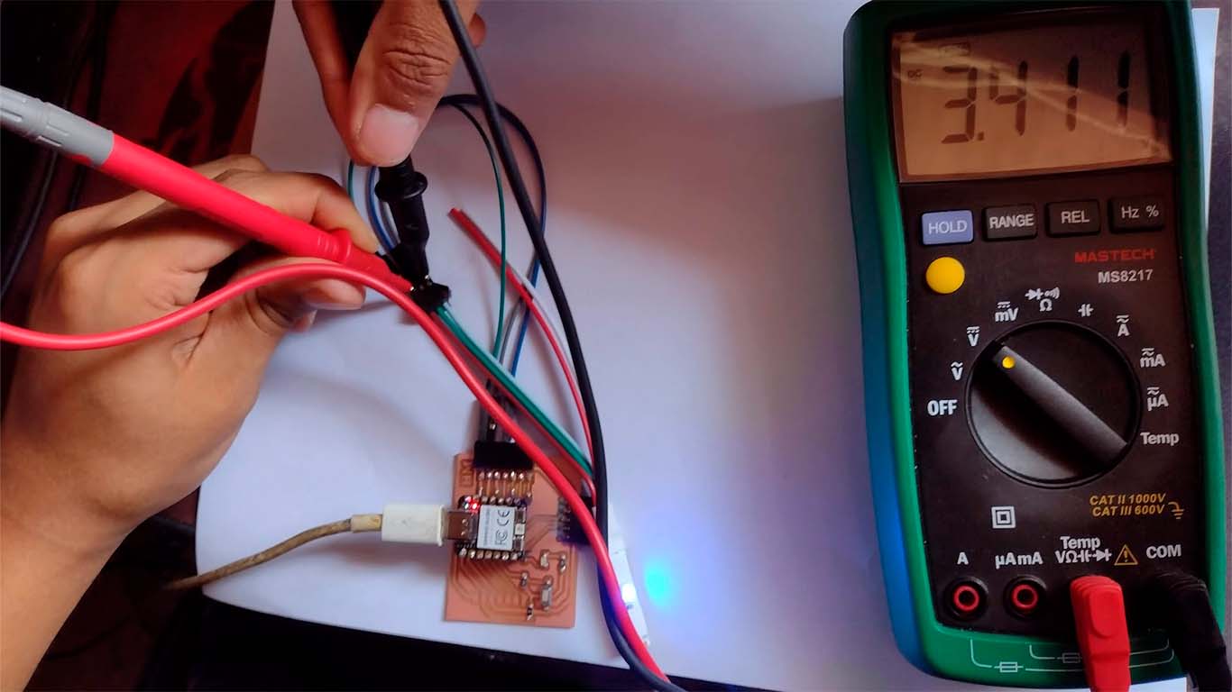
NEOPIXEL - VOLTAGE
Now with the multimeter we measured the VOLTAGE generated for the NEOPIXEL where we obtained a value of 3.411 when measuring it. Here we can take some photographs at the time of measurement.
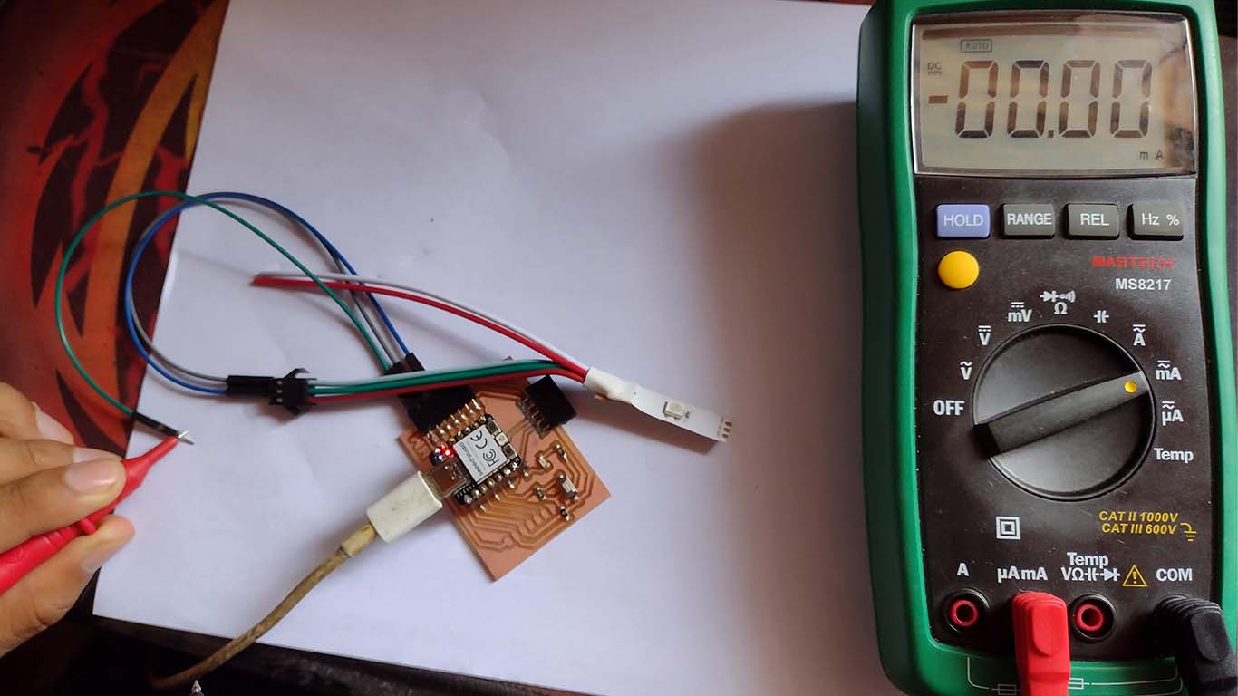
NEOPIXEL - AMPS
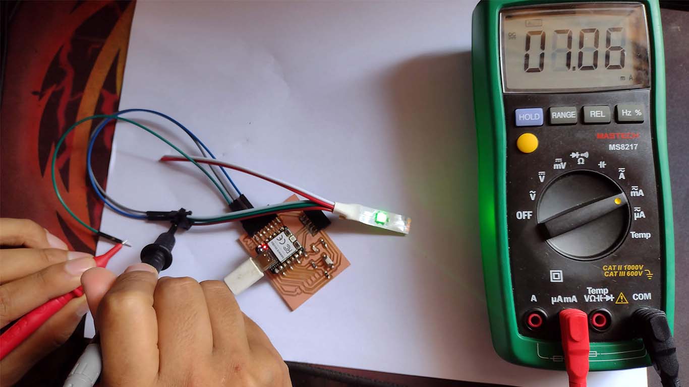
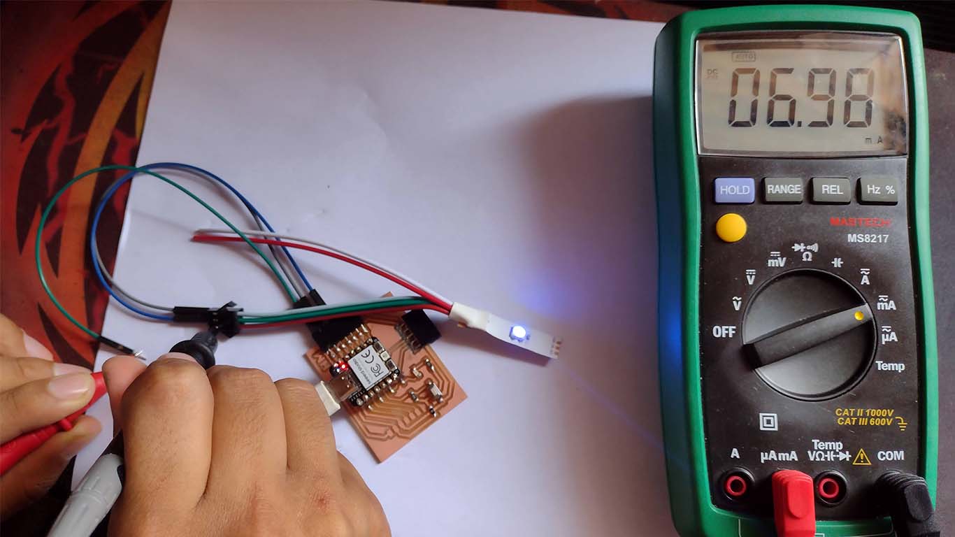
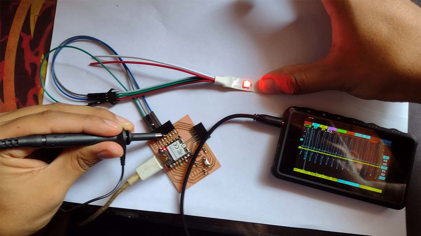
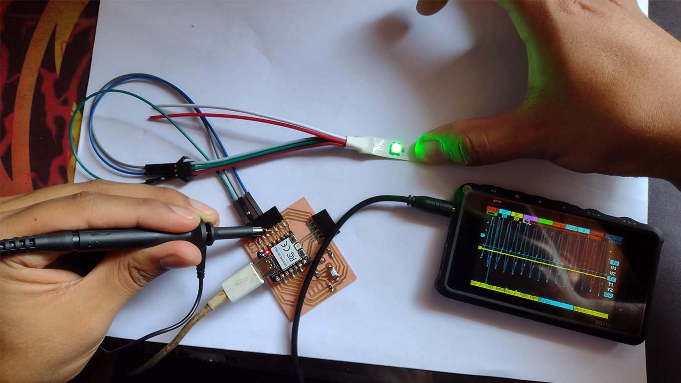
NEOPIXEL - OSCILLOSCOPE
With the help of the oscilloscope I was able to analyze the behavior of the waves in the NEOPIXEL. Here are some photographs of them in which we can see that waves continue to be generated when they come into contact with any pin on the board.
MAX32625PICO
With the help of the oscilloscope I was able to analyze the behavior of the waves in the NEOPIXEL. Here are some photographs of them in which we can see that waves continue to be generated when they come into contact with any pin on the board.
Group 2:
- Renson Samaniego
- Wilber Giron
- Ronal Noel
Ronal Vilca Apolin
During this week, we also carried out teamwork through the ZOOM platform. To do this, we used a multimeter to perform power consumption tests on a device or load. In this case, we focused on measuring the consumption of energy of a minipump.
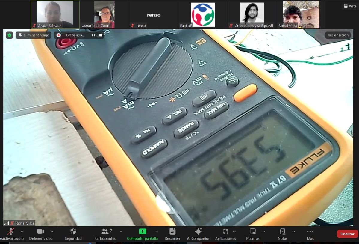
Fluke 87V Industrial Multimeter
For voltage, resistance and continuity tests, we use the Fluke brand multimeter. It is a piece of equipment of excellent quality and highly recommended for its precision and reliability.
Main features
- True RMS AC voltage and current for accurate measurements for non-linear signals.
- Selectable filter for accurate frequency and voltage measurements in variable speed drives.
- 0.05% DC Accuracy 6000 counts, 3-3/4 digits.
- 4-1/2 digit resolution for accurate measurements (20,000 counts).
- Measurements up to 1000 V AC and DC.
- Measurement up to 10 A; 20 A for a maximum of 30 seconds.
- Integrated thermometer that avoids the need to carry an additional tool (temperature probe included).
- FFrequency up to 200 kHz and duty cycle (in %).
- Resistance, continuity and diode test.
- 10,000 µF capacitance range on motors and components.
- Recording of minimum, maximum and average values with alarm for automatic capture of variations
- Peak capture to record transients as fast as 250 µs
- ll inputs have been updated to the 3rd edition of ANSI/ISA S82.01 and EN61010-1 CAT IV 600V and CAT III, 1000 V. They can withstand impulses greater than 8000 V and reduce risks related to overloads and spikes.
Tests with the Multimeter
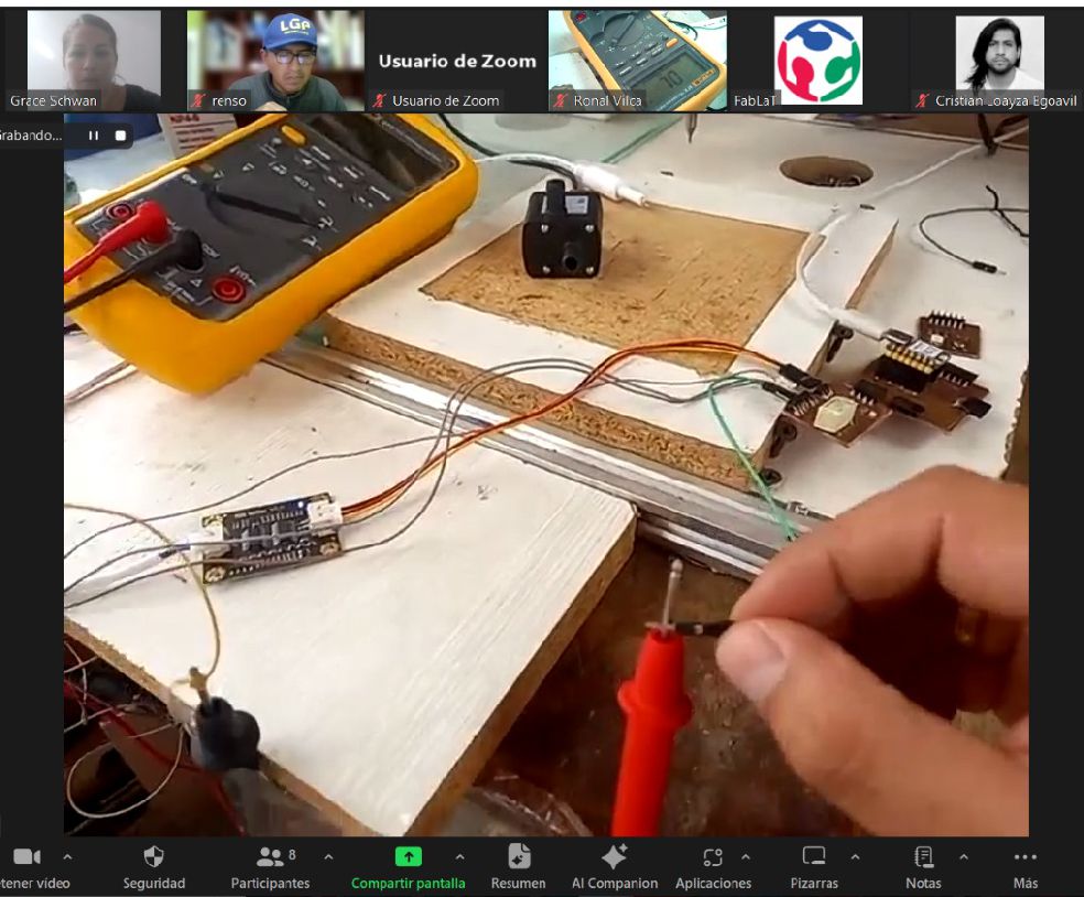
To carry out the power consumption tests, we use a multimeter, a mini pump model JT-180B, a constructed output board, the XIOA RP2040 and a 6V battery with a capacity of 4A.
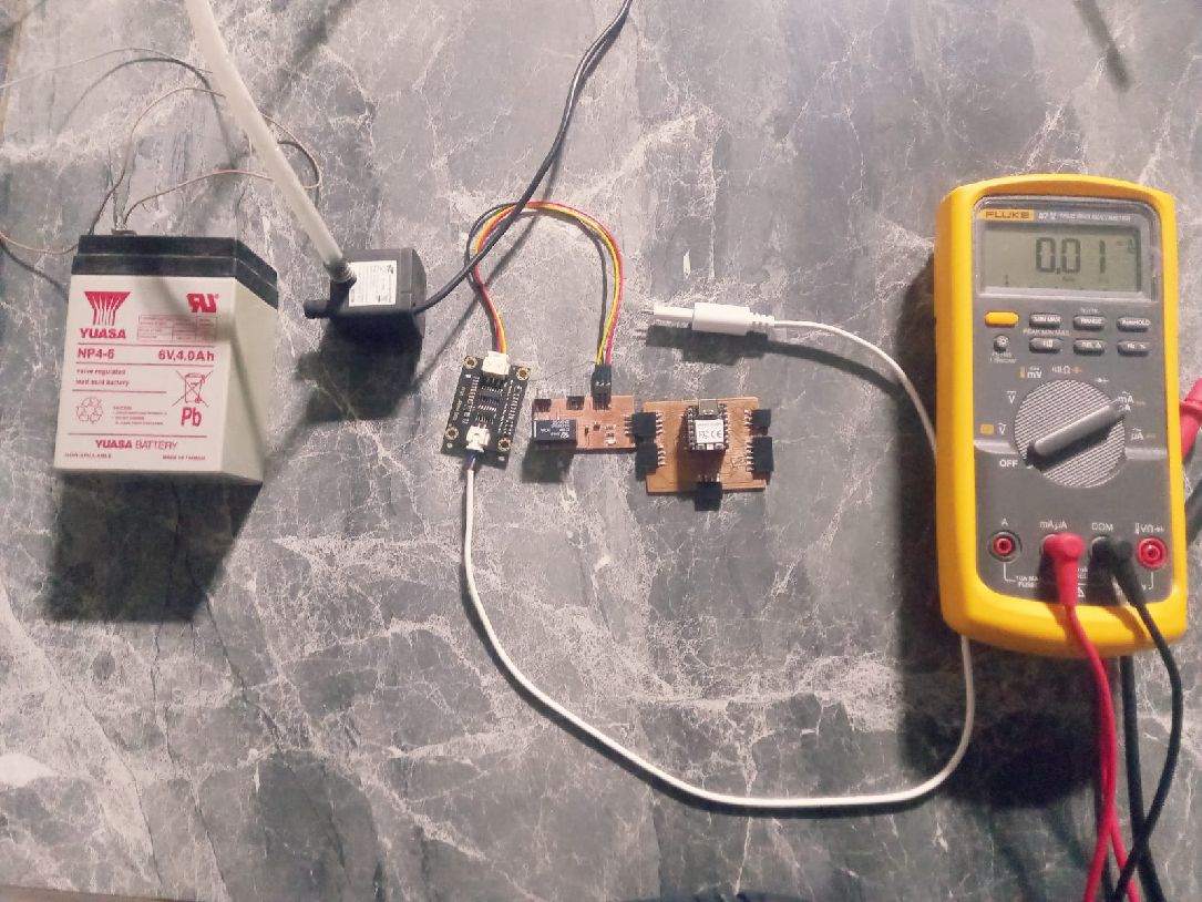
The first step is to place the components on the motherboard: the controller or board with the relay, the TDS sensor and the battery.
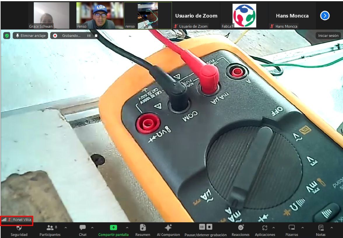
It is also important to position the multimeter correctly, with the black lead in the COM position and the red lead in the mA position.
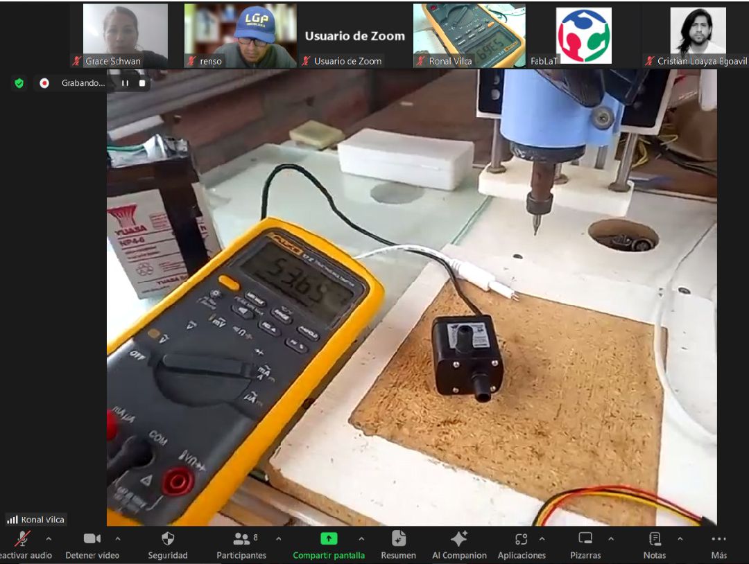
When carrying out the measurements, it can be seen that the energy consumption of this minipump is 53.95 mA. This information is crucial to understand the energy requirement of the pump and ensure adequate power in the circuit design.
During our experience this week with the multimeter, we understood its vital importance in the electronic field. This device allows us to measure and confirm key values of electronic components, such as resistance, perform diode tests, evaluate the continuity of circuits and, fundamentally, determine the energy consumption of our loads, as in the case of the minipump. This information is crucial to selecting a suitable battery and correctly sizing the electronic components needed for our project.