This week's assignment was:
This week it is about making a machine and for this assignment the work is group work. Here are the tasks we must fulfill:
- Design a machine that includes mechanism+actuation+automation+application
- Build the mechanical parts and operate it manually
- Document the group project and your individual contribution
- Actuate and automate your machine
- Document the group project and your individual contribution
GROUP ASSIGNMENT
Here I leave the link to go to the group assignments page.
clic here to visit the WEEK 10 GROUP ASSIGNMENT PAGE
PRESENT MY MACHINE GLOBALLY
The day after the INPUT DEVICES class, we met with our instructors to give us feedback on the class. They will explain to us how the inputs work, what they are asking us for in the orders and to resolve our doubts. Here I leave the SLIDE and the VIDEO of our developed assignment.
INDIVIDUAL ASSIGNMENT
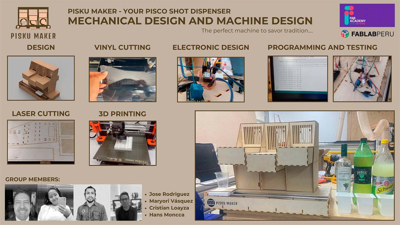
MECHANICAL DESIGN
Our group was divided into all the tasks that we were going to develop this assignment. I was responsible for the 2D and 3D design, and since I was going to be in charge of the design, I was in charge of the assembly of the machine and finally, I was also part of the testing for its development.
CONCEPT
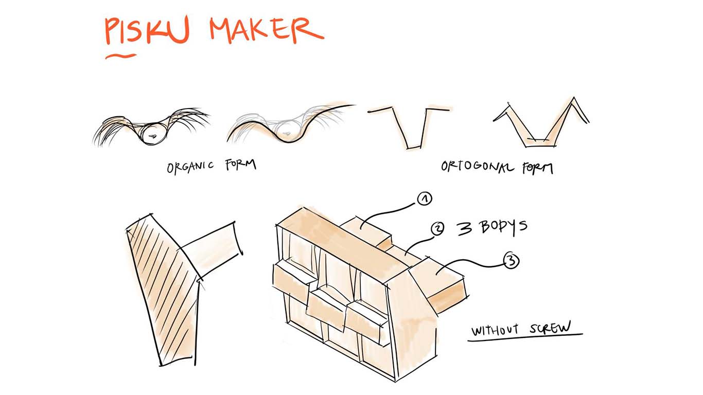
To design the machine we thought of many ways in which it could work. The truth is that we were afraid of how to start and what we were going to develop. Therefore, when recapitulating the entire FAB ACADEMY and what was done each week, we concluded that the machine should be all PRESS FIT to avoid using screws or other components since we had 3mm PLYWOOD as material. From this, we developed design sketches and what was left was one that looked like a building. The majority of the group are architects and we liked the mix between machine and architecture so much that we developed an architectural model-type machine.
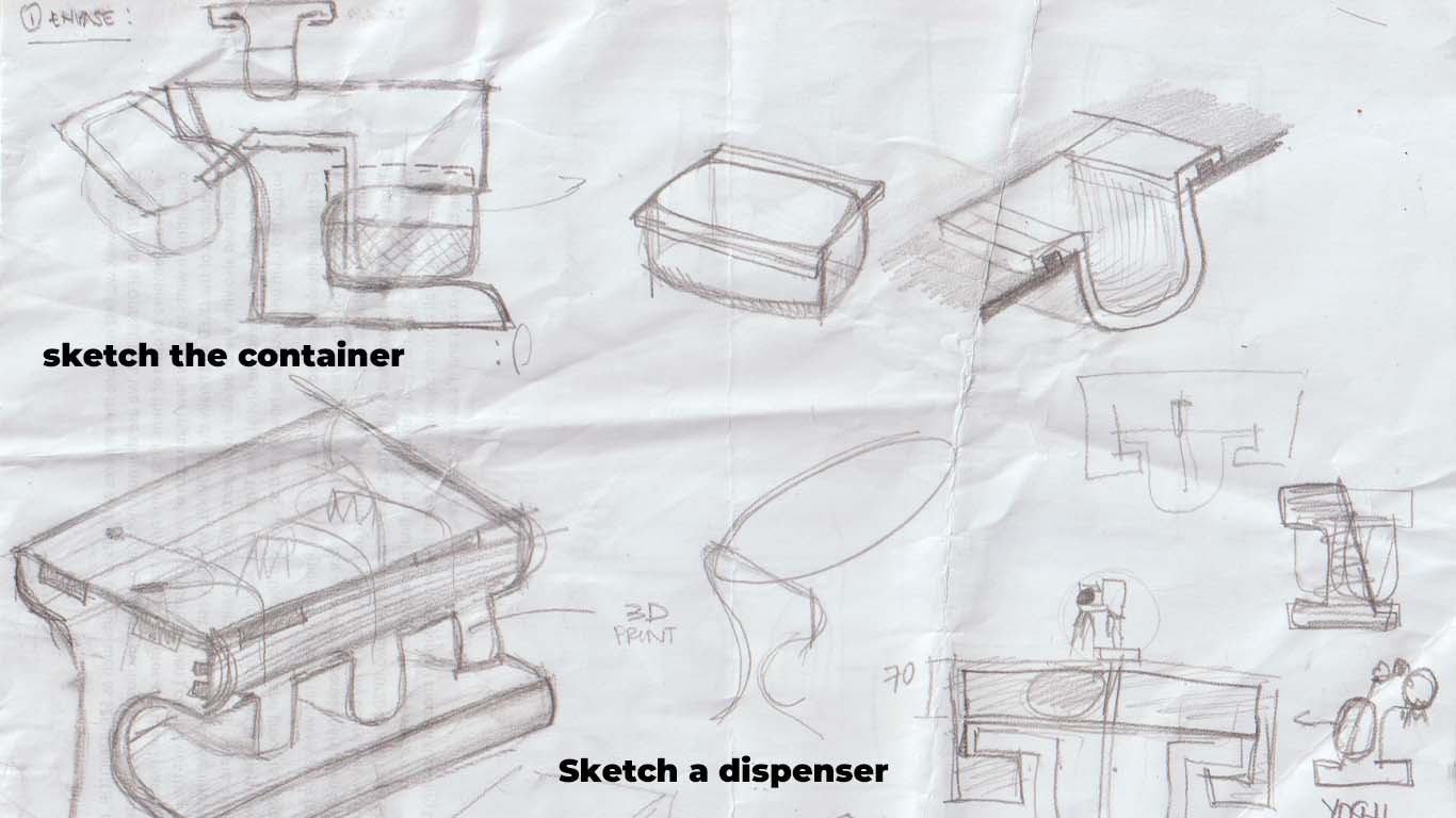
DESIGNING A MACHINE - SKETCH
To begin the design of the machine, we began to make sketches to understand how it was going to work and how to place the components that we were going to have. Here are some photographs of sketches that I was able to recover at the time of design.
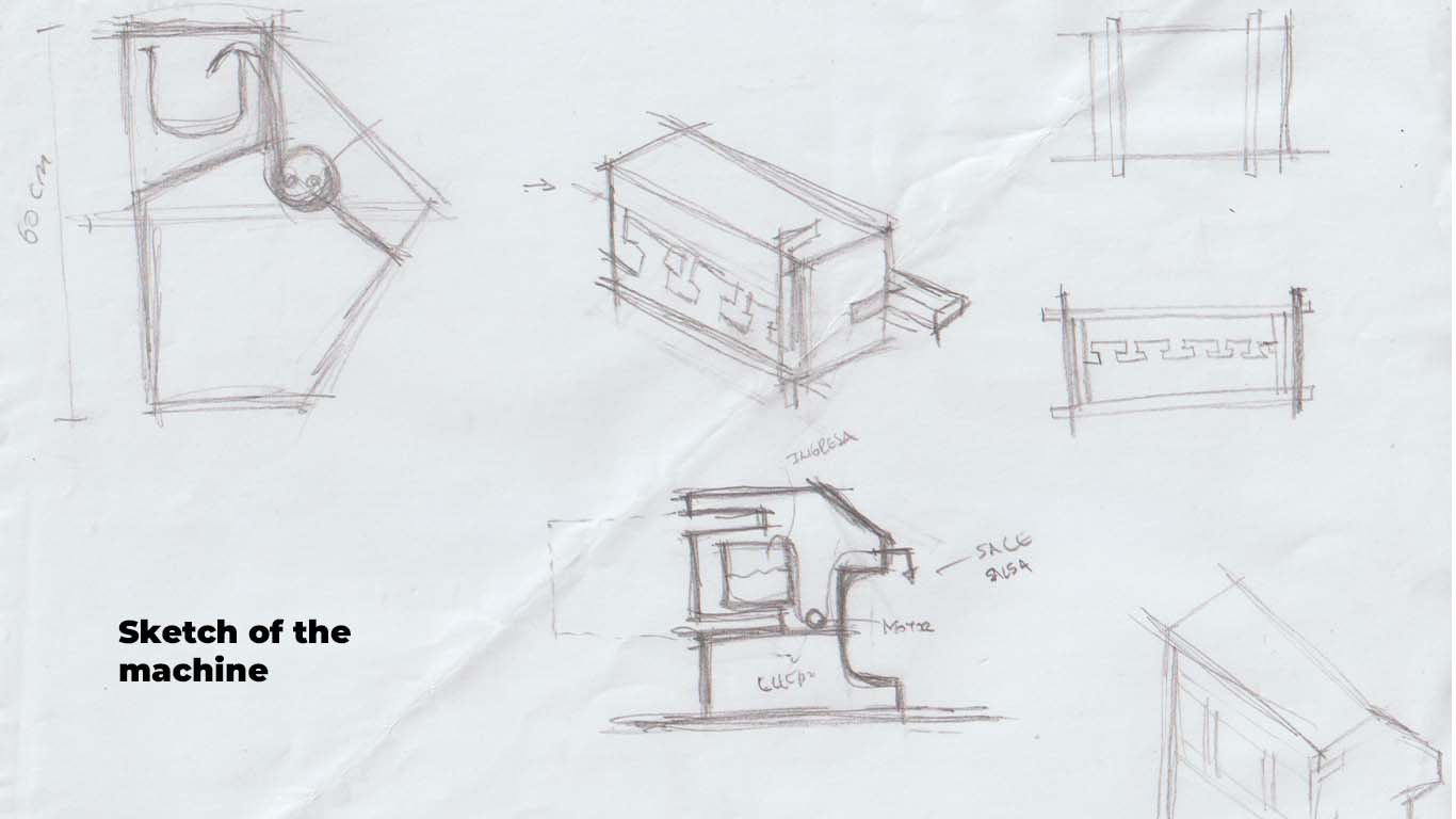
Finally, after talking about the shape, size, and characteristics that the machine was going to have. My colleague Maryori made a sketch closer to the design, where we gave it a compact shape according to the central idea and that everything is PRESS FIT.
DESIGN 2D AND 3D
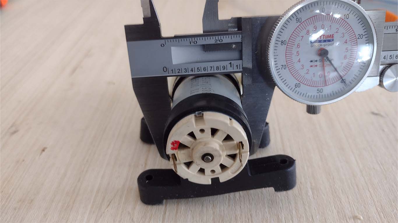
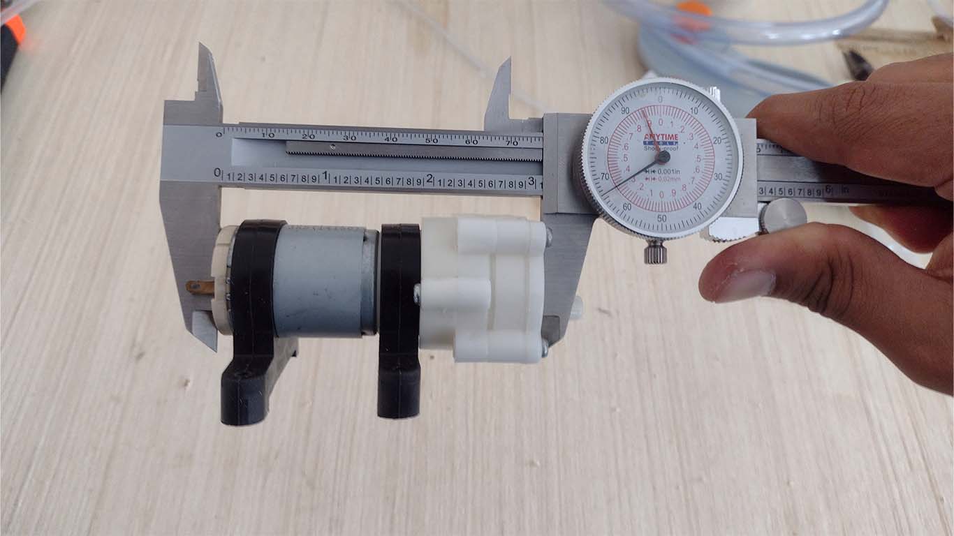
After having an idea of the design in sketches, I began to make the design in AUTOCAD and FUSIÓN at the same time to be able to review how it was turning out. Before doing so, I had to analyze the measurements of the electronic components that we were going to use such as motors, boards and stepper motors.
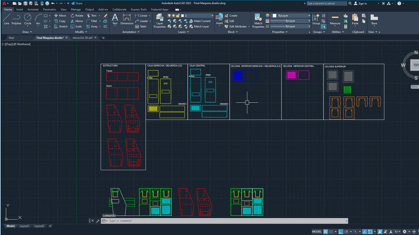
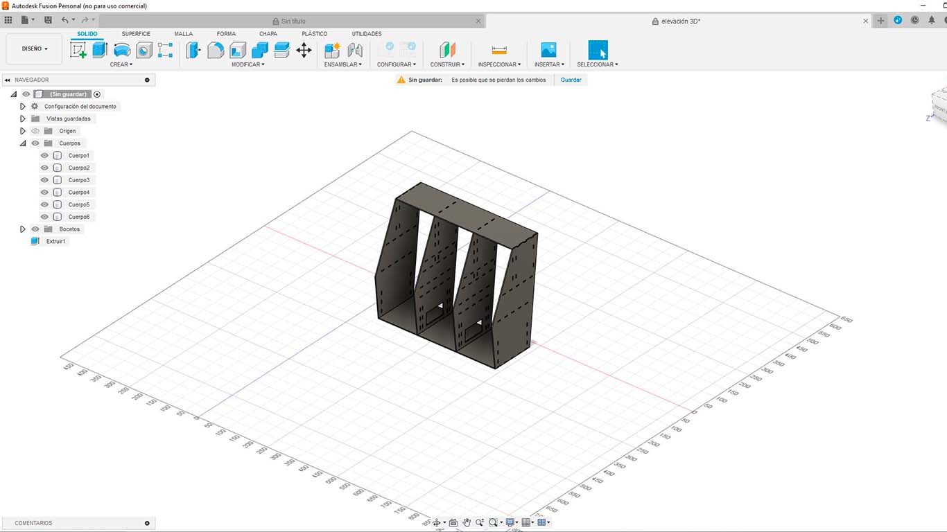
From there, I began to draw and design the machine in 2D and 3D in the programs mentioned above. Here are some photographs of the design. It seemed appropriate to start with the dispenser part, where I saw that we were going to have more components to place and also hide.
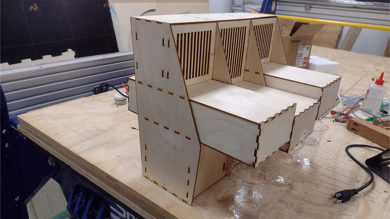
First I started with the structure, where we ended up having 3 liquid stations to place the drinks we wanted to prepare. From this, have a structure that can have ruffles to be able to empty the liquids into a glass. I remembered that everything must be PRESS FIT, so I tried to carry out very detailed work to avoid connection problems and also supported the assignment made in week 3 about the measures we must have for the PRESS FIT.
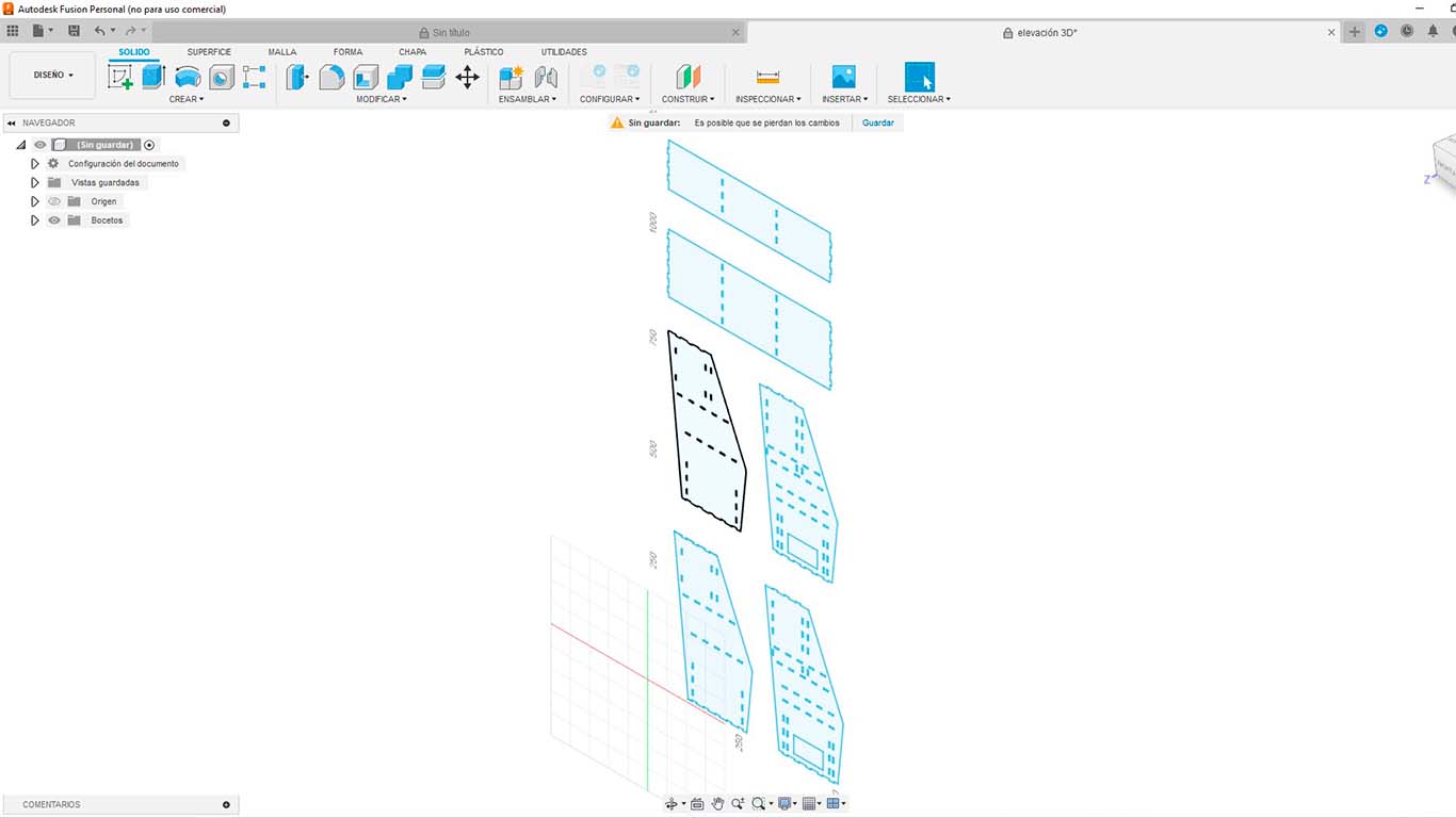
For the design, work in both programs to achieve a better understanding of the pieces and know where each piece is from. Here is a photograph of importing the parts to FUSION.
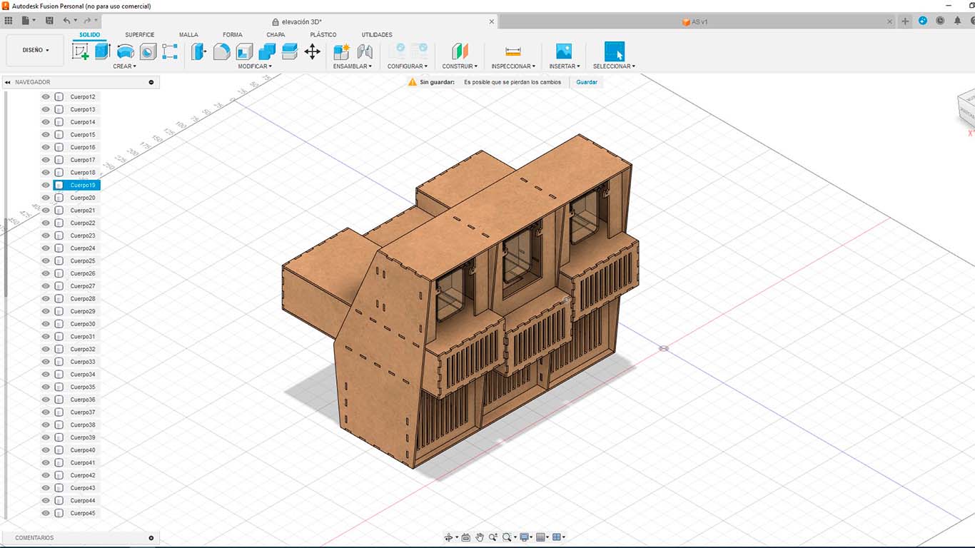
Then I began to model the structure of the dispenser, where I first started with the exterior, then the areas where the peristaltic pumps were going to go and finally the part of the beverage containers. Here I show you a gallery of screenshots taken when doing the 3D modeling
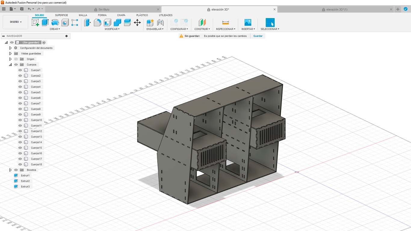
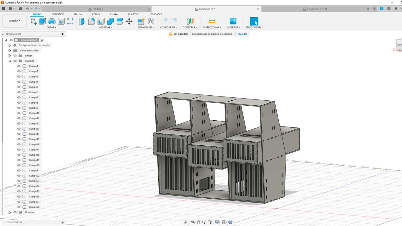
Finally, after fitting all the pieces of the structure, the pump areas and the containers, we obtained the following design, which would be the dispenser part of the machine.
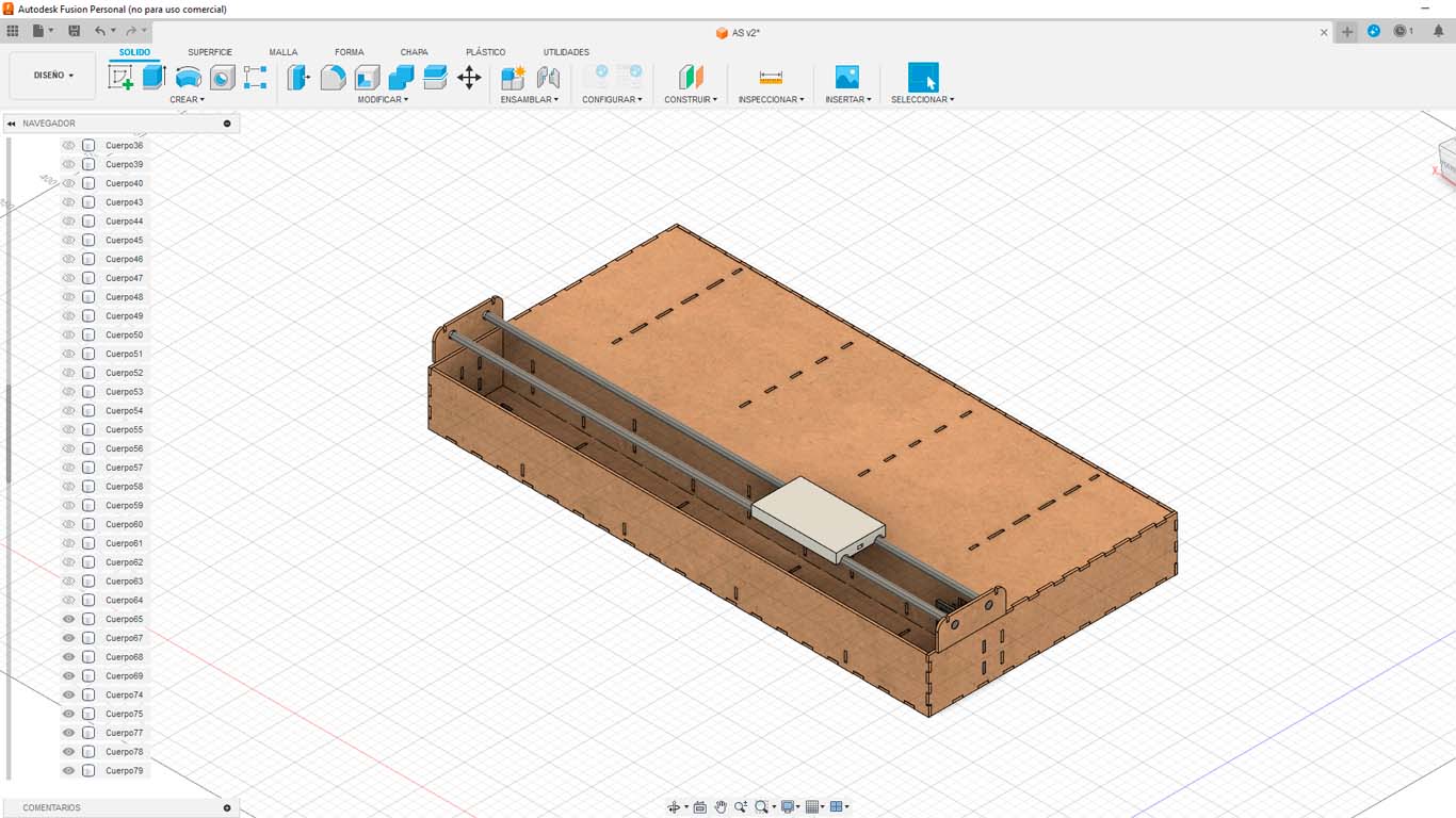
After obtaining the design of the dispenser, I went on to design the base, where we were going to have a machine on an axis that runs through the 3 stations and while it runs, it can be filled with the liquids we had. Here are some screenshots of the process and just like the dispenser, everything had to be PRESS FIT, where we also took into account the measurements of the components to be used.
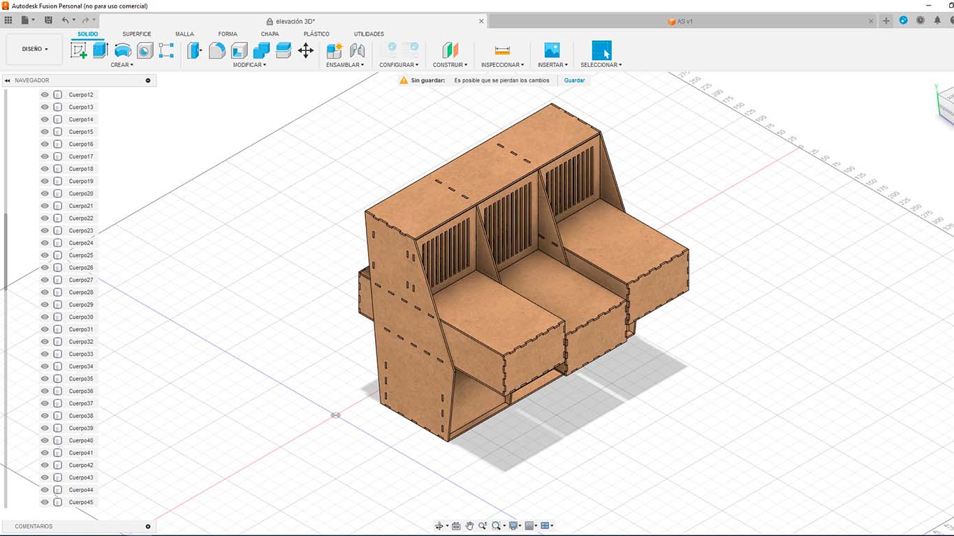
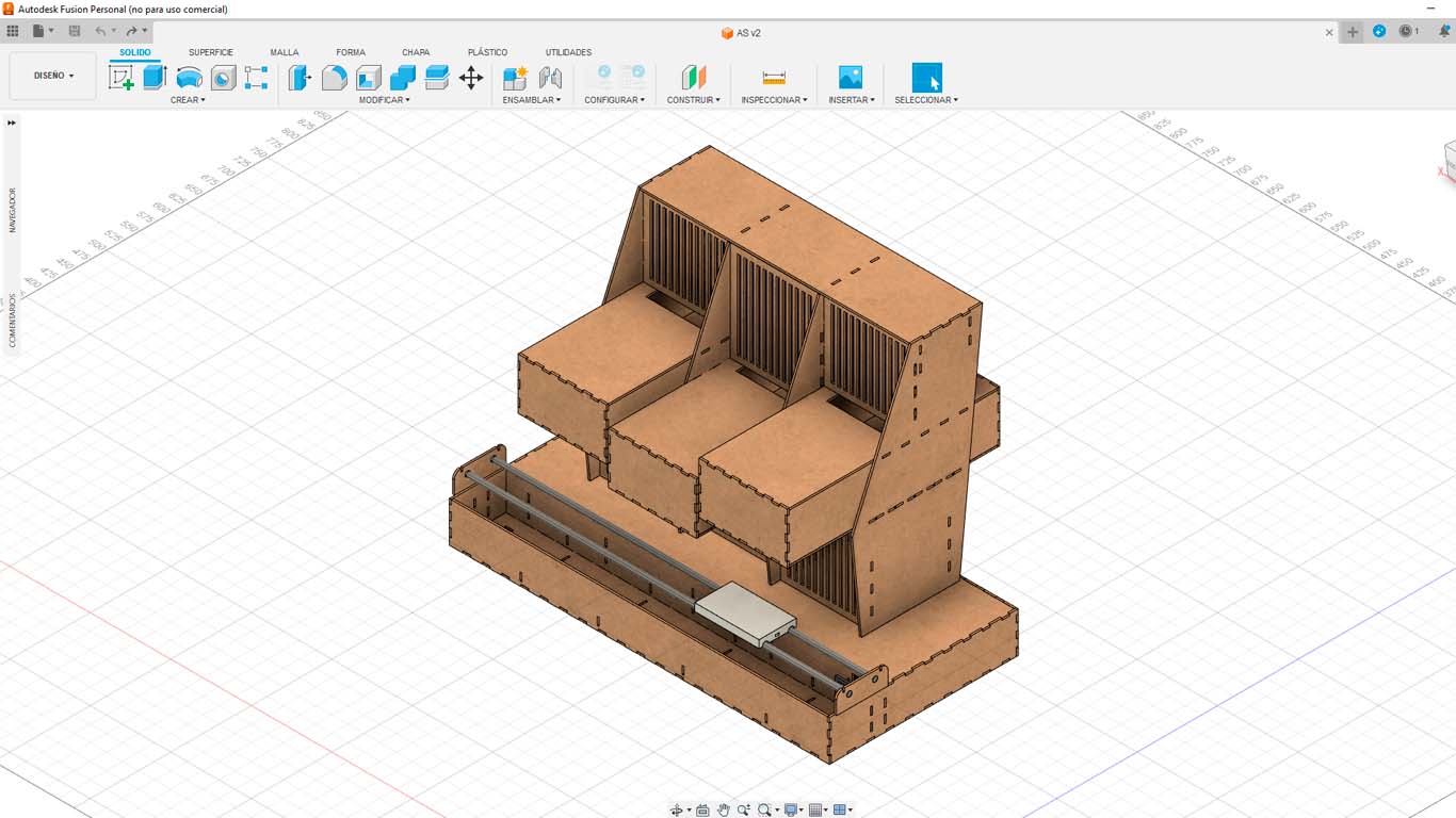
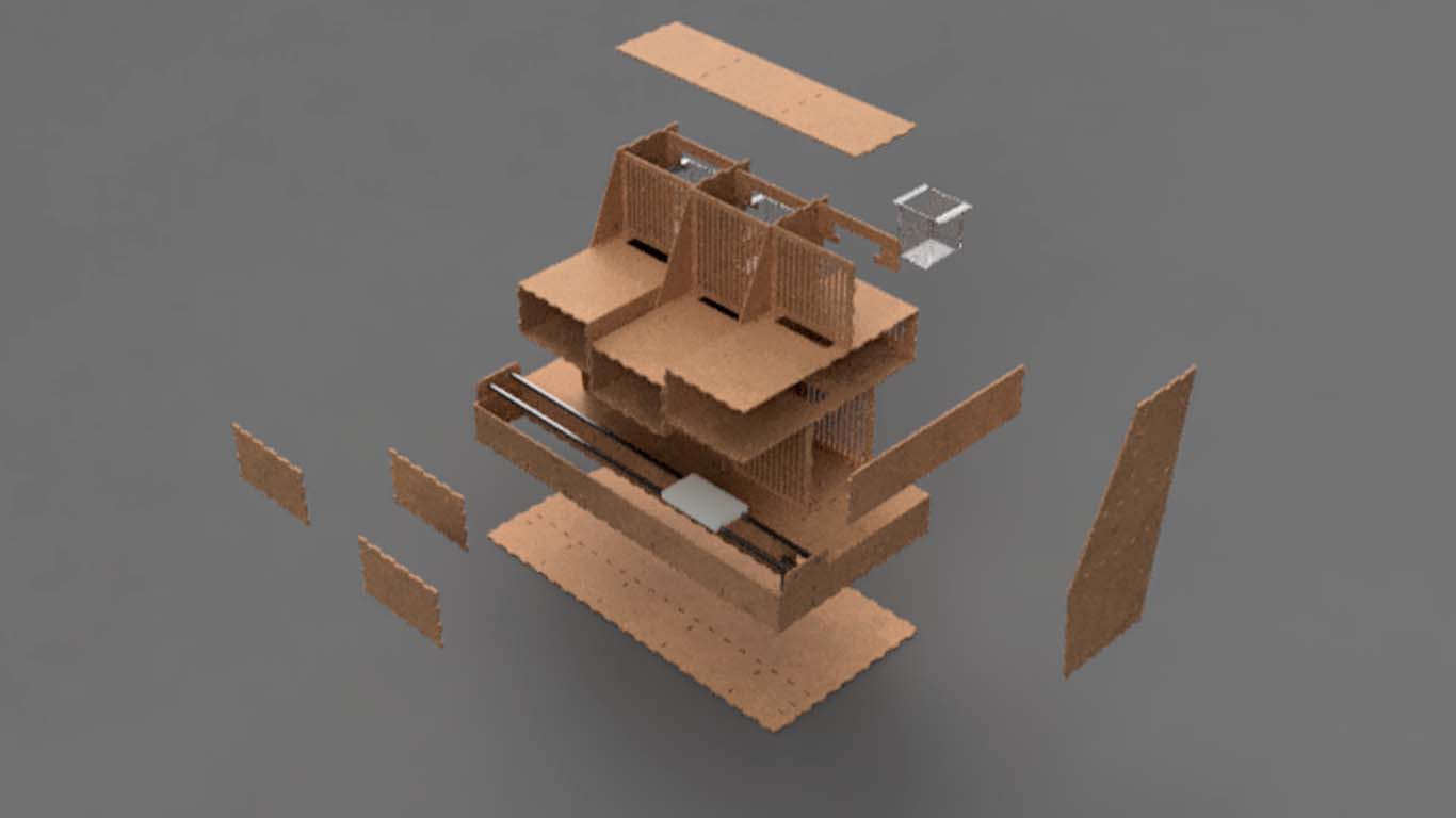
Finally, after having the design of the base where we are going to have a travel axis, we join both parts and obtain the following model. We really liked the design of how everything was going to look.
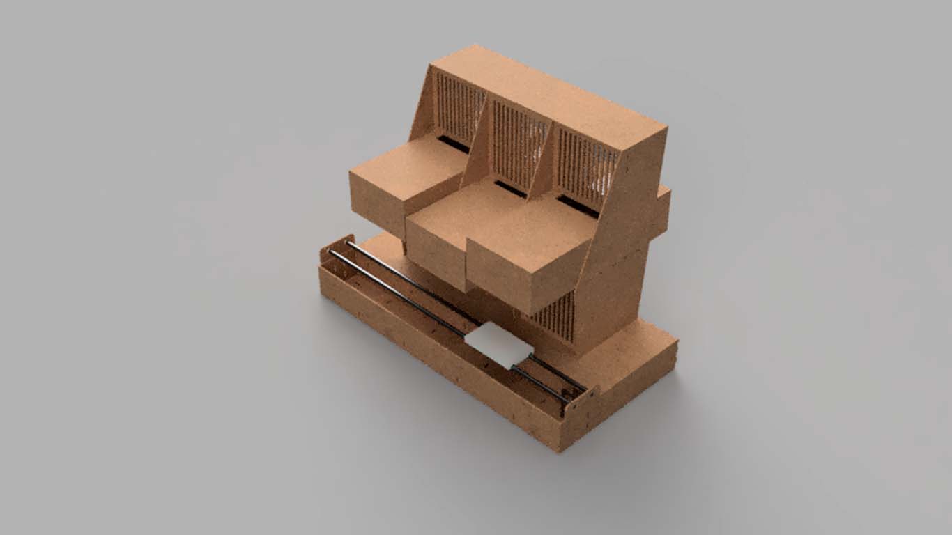
After checking the design and seeing if everything was okay. I went on to render and showed it to my colleagues so they could give me a critique of the design, some things that we were going to change and the truth is that it turned out very well. So we move on to the realization and assembly stage.
LASER CUTTING AND 3D PRINTING
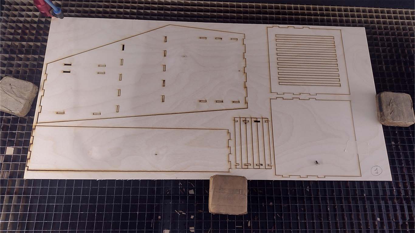
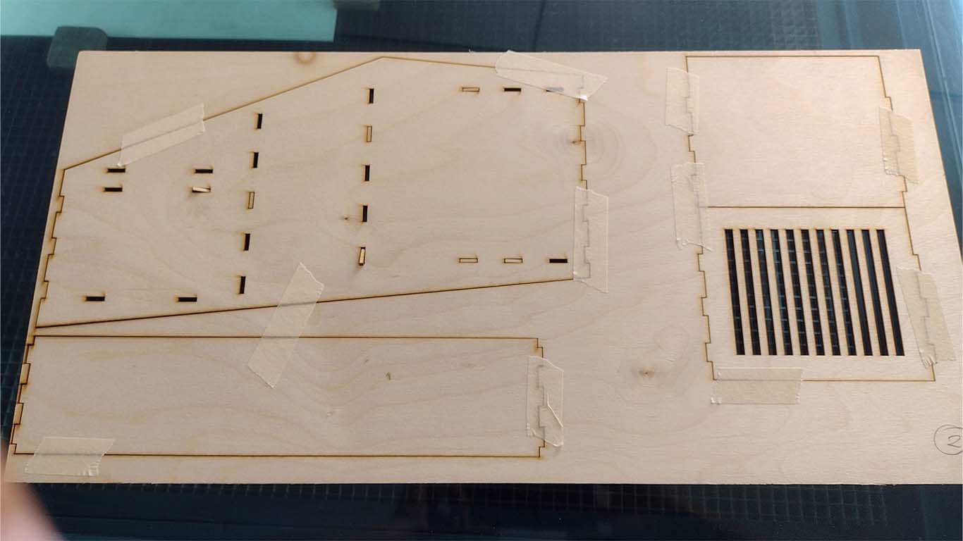
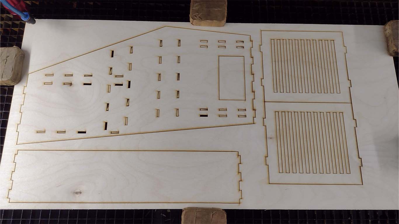
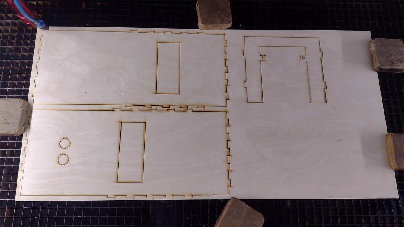
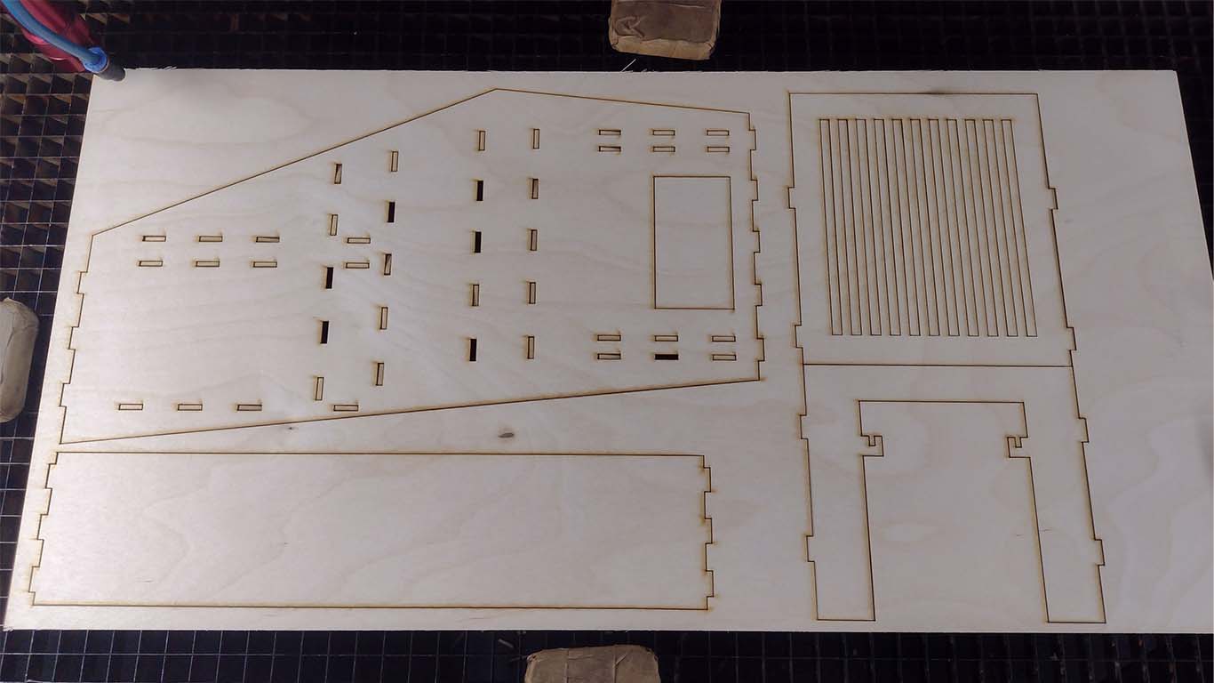
After checking that the design and the PRESS FIT were going to work, we moved on to the realization stage. For the machine we were going to need to laser cut and 3D print some components. First, I had all the pieces of the structure and base laser cut. Here are some photographs of the cuts, approximately we used 9 PLYWOOD sheets of 30 x 60 cm for the entire machine.
Here is a screenshot of the exploded view made in AUTOCAD to send it to be laser cut.

Below are some screenshots of the cuts of all the pieces of the machine developed to send it to laser cut the PLYWOOD boards.
Likewise, I had some components that we were going to need 3D printed, such as the base of the glass and the liquid containers. Here are some screenshots of the procedure.
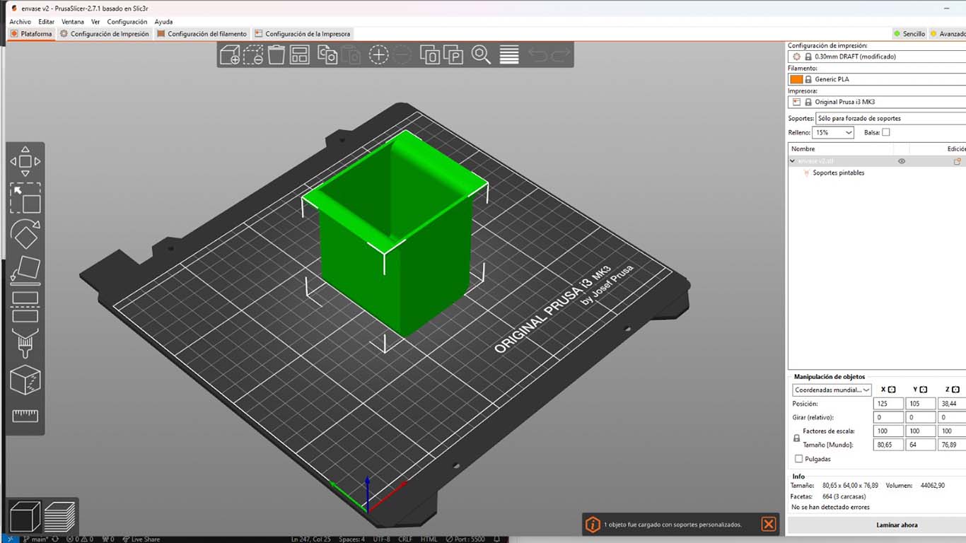
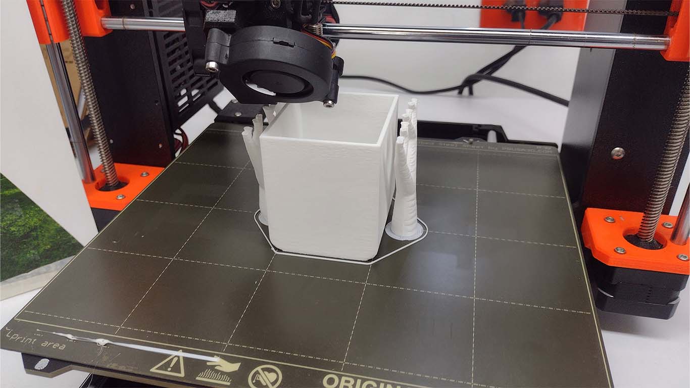
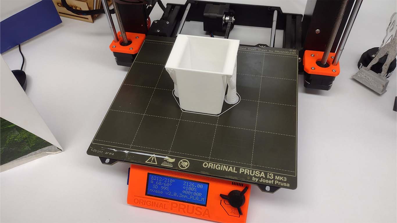
On the other hand, I also had the base where we were going to put the glasses that were going to receive the liquids to be 3D printed. This support was going to move throughout the machinery.
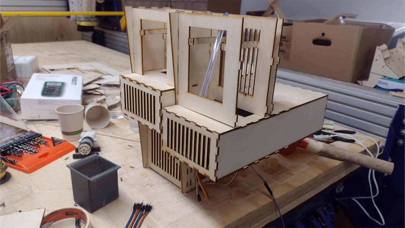
MACHINE ASSEMBLY
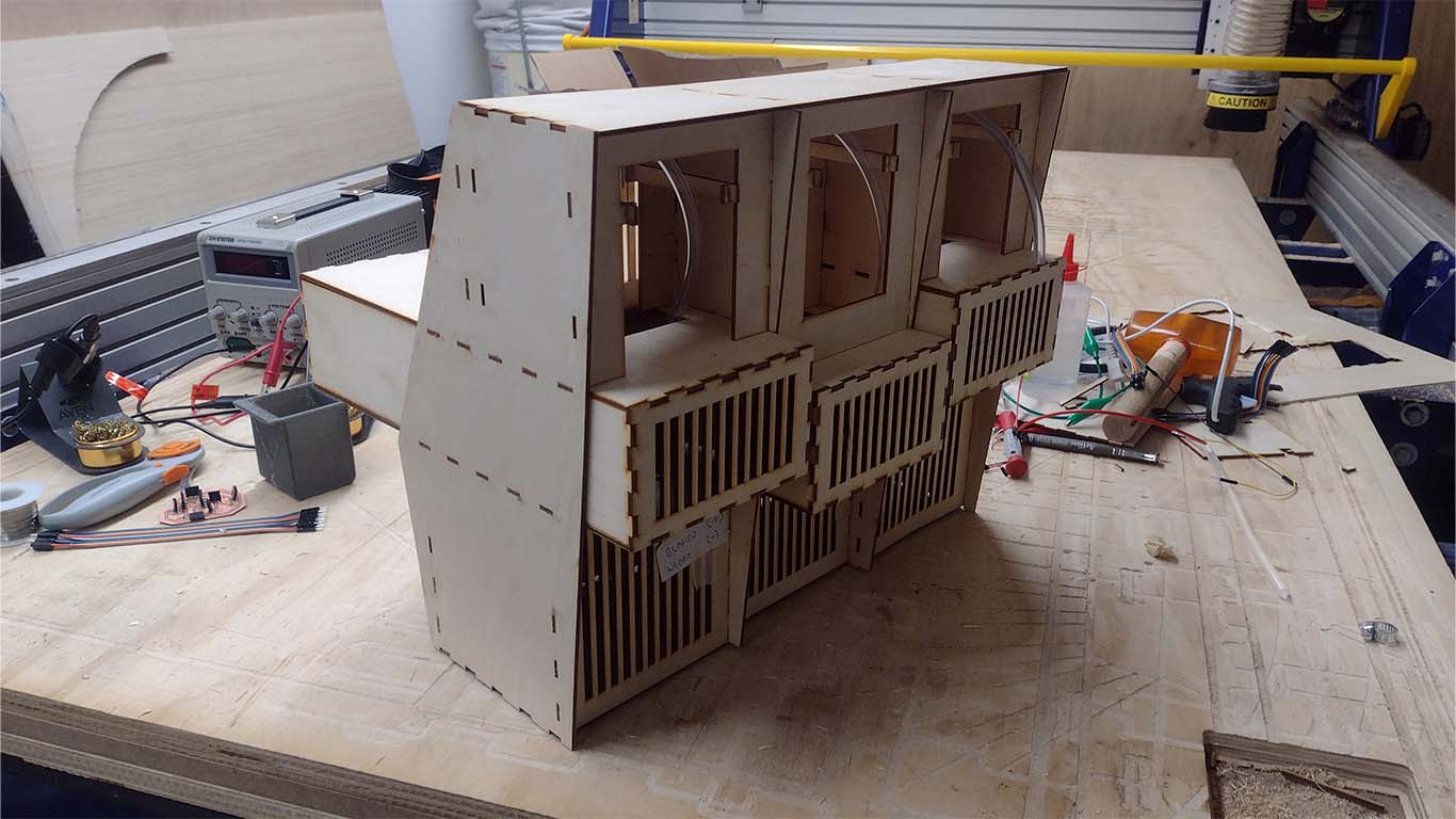
After getting all the components cut, I went on to assemble the machine to check if the PRESS FIT fit very well and that all the parts can be assembled. I had difficulties because when assembling I had some PRESS FIT problems that took me a while to solve. In addition, I took the opportunity to place the peristaltic motors, stepper motor and some circuits because they were already ready for placement. Here are some photographs of the procedure.
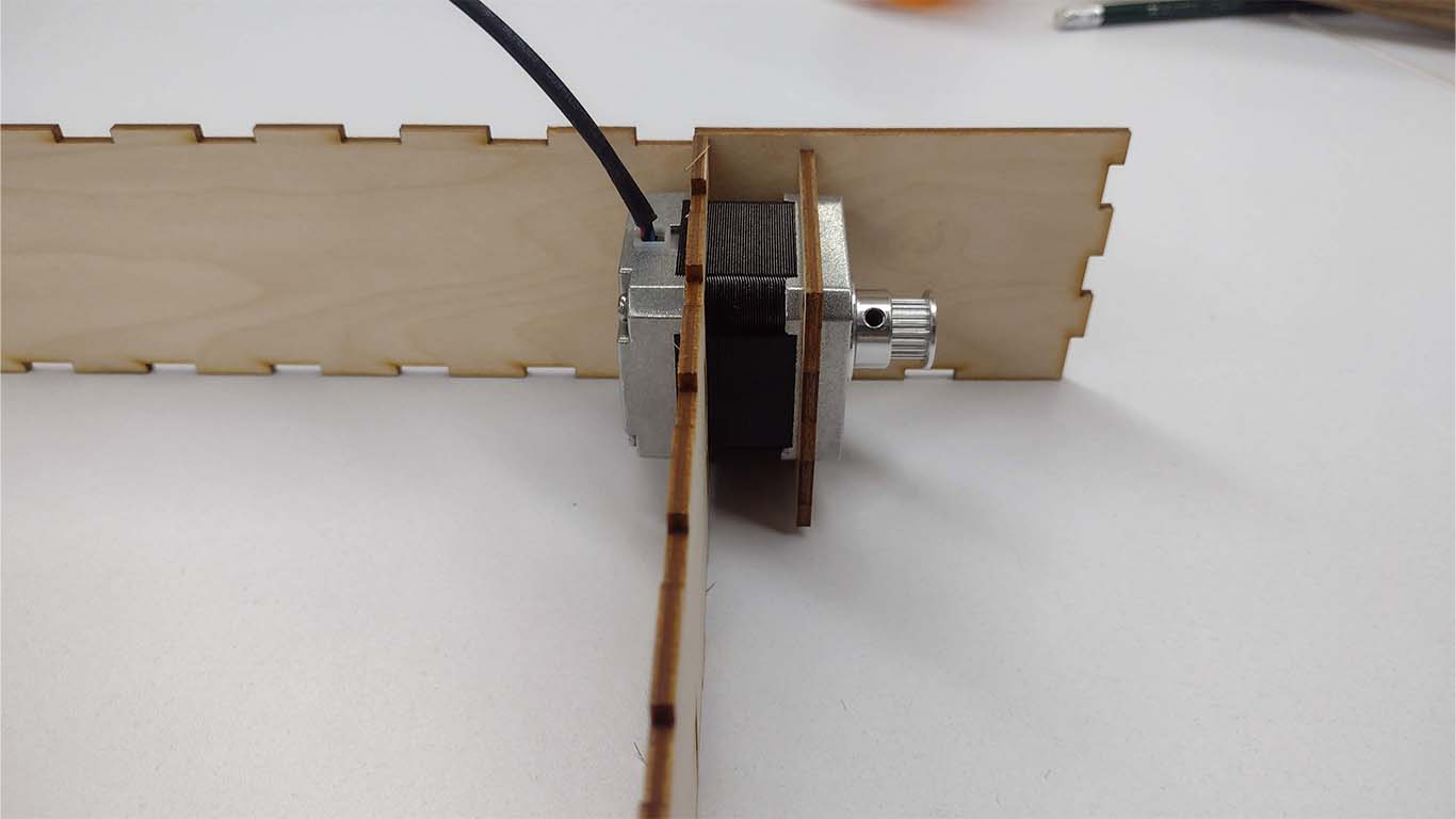
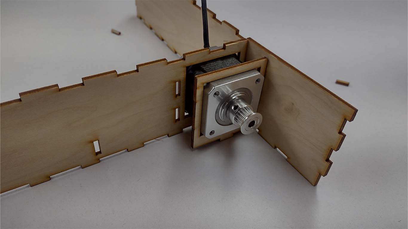
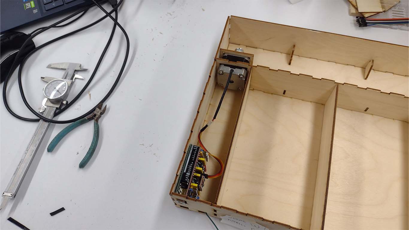
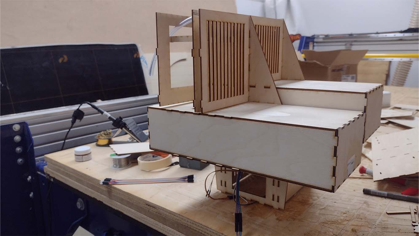
First I began to assemble the base of the machine, where I located the entire stepper motor mechanism for its operation.
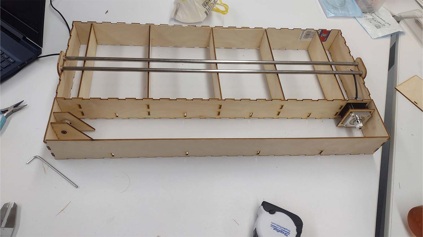
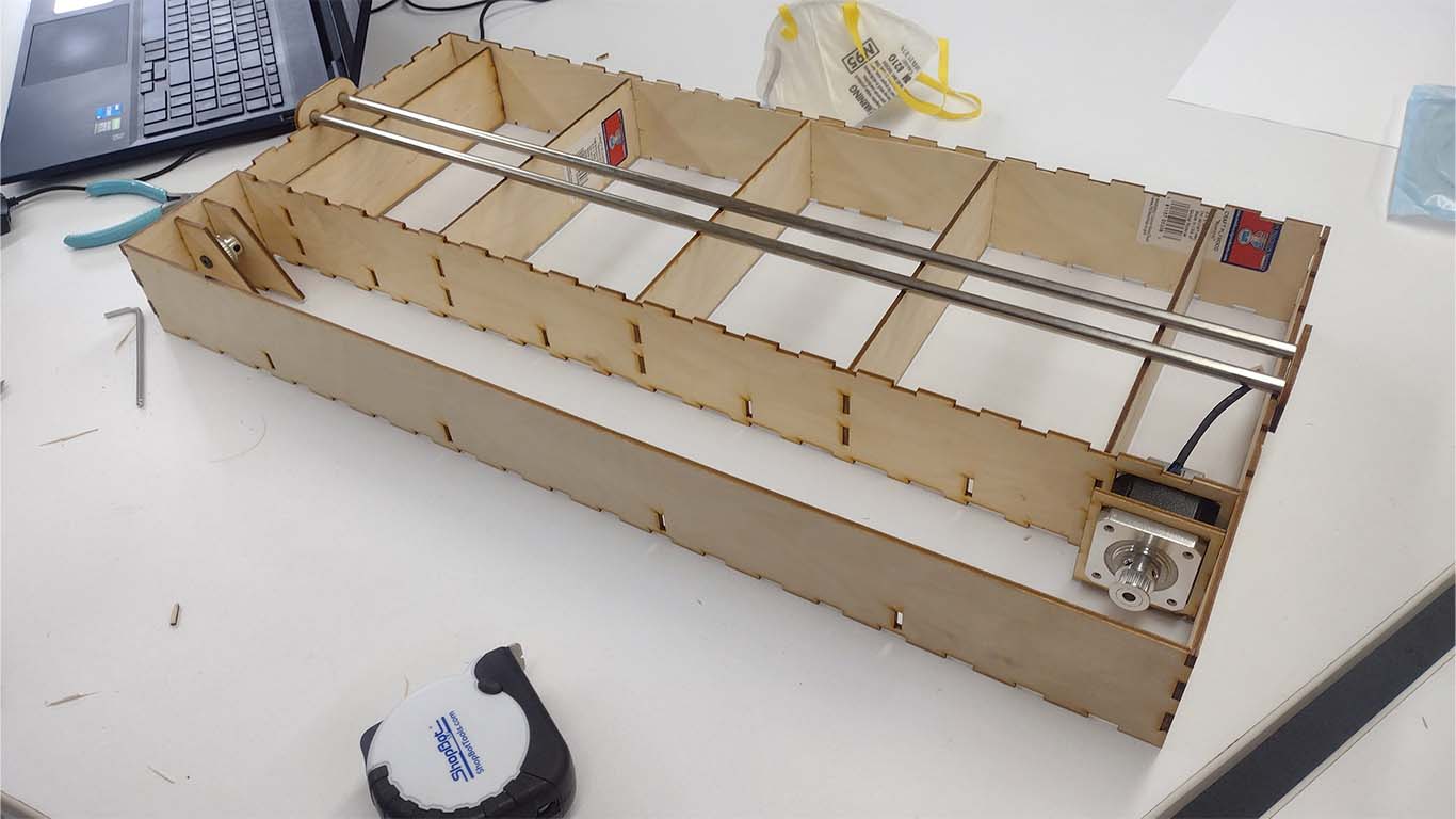
Then I assembled the entire base adding the other pieces that this part of the machine included such as supports, sides and completing the stepper motor mechanism.
Finally, as my colleague Cristian was able to advance the electronics part and the operation of the stepper motor, I began to place it on the base and fix it to begin the dispenser part.
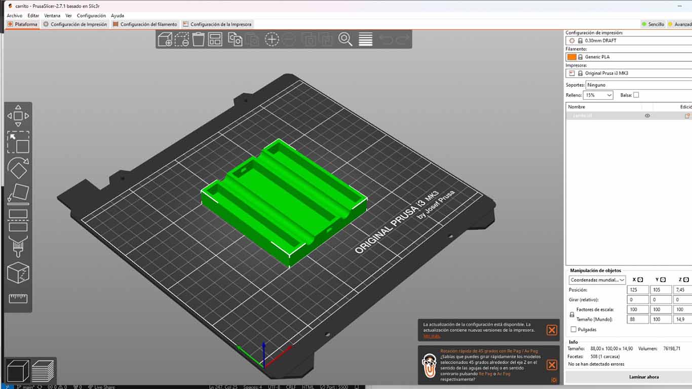
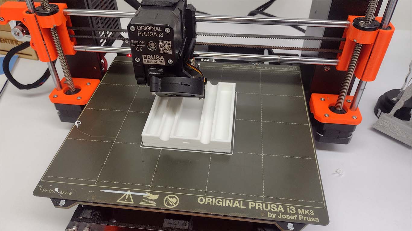
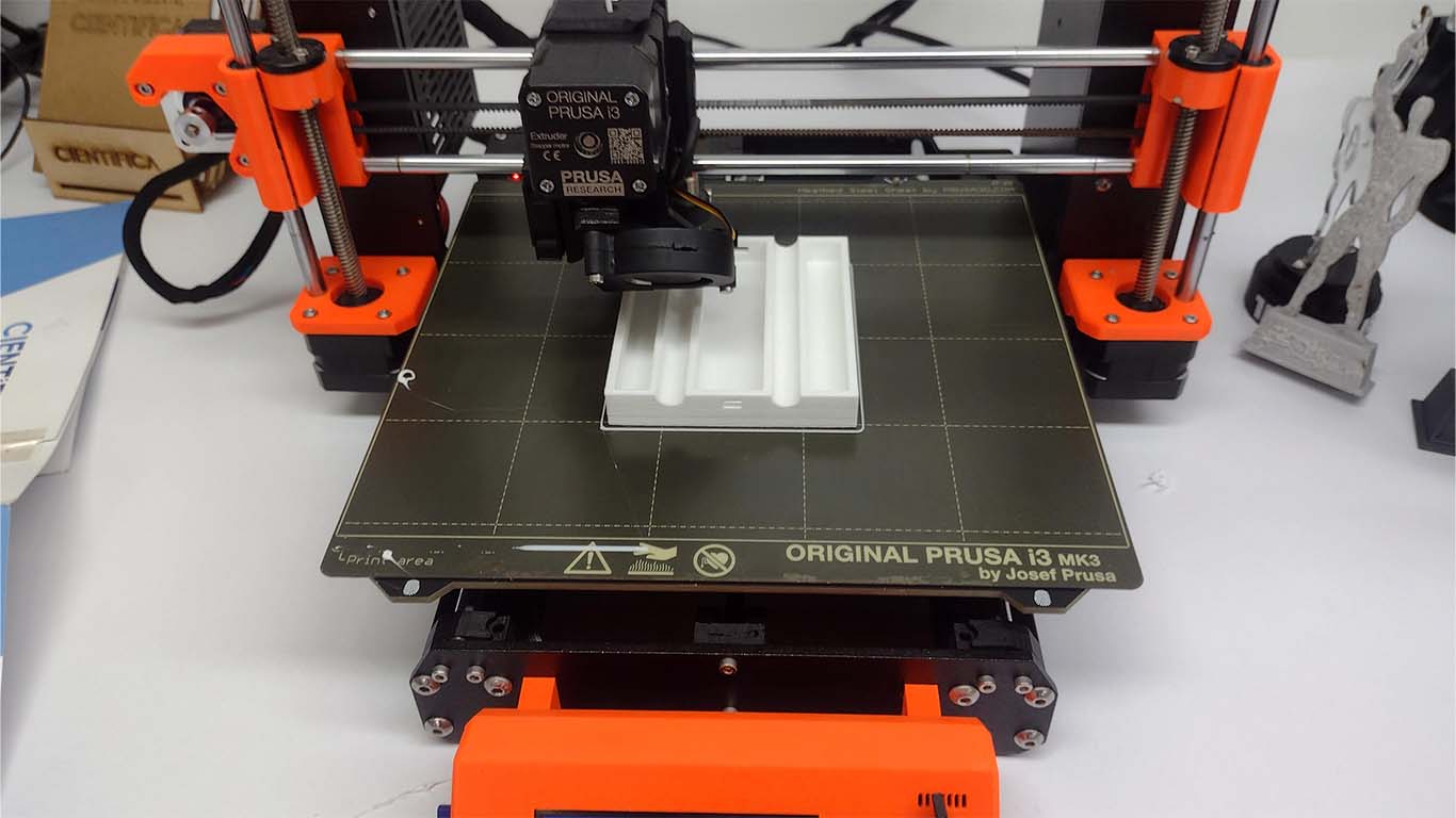
I made a small simulation model of the base that was going to move on the axis of the stepper motor so that later, with the measurements, I could make the 3D print, here is an example of testing the travel and fixing of the steel rods.
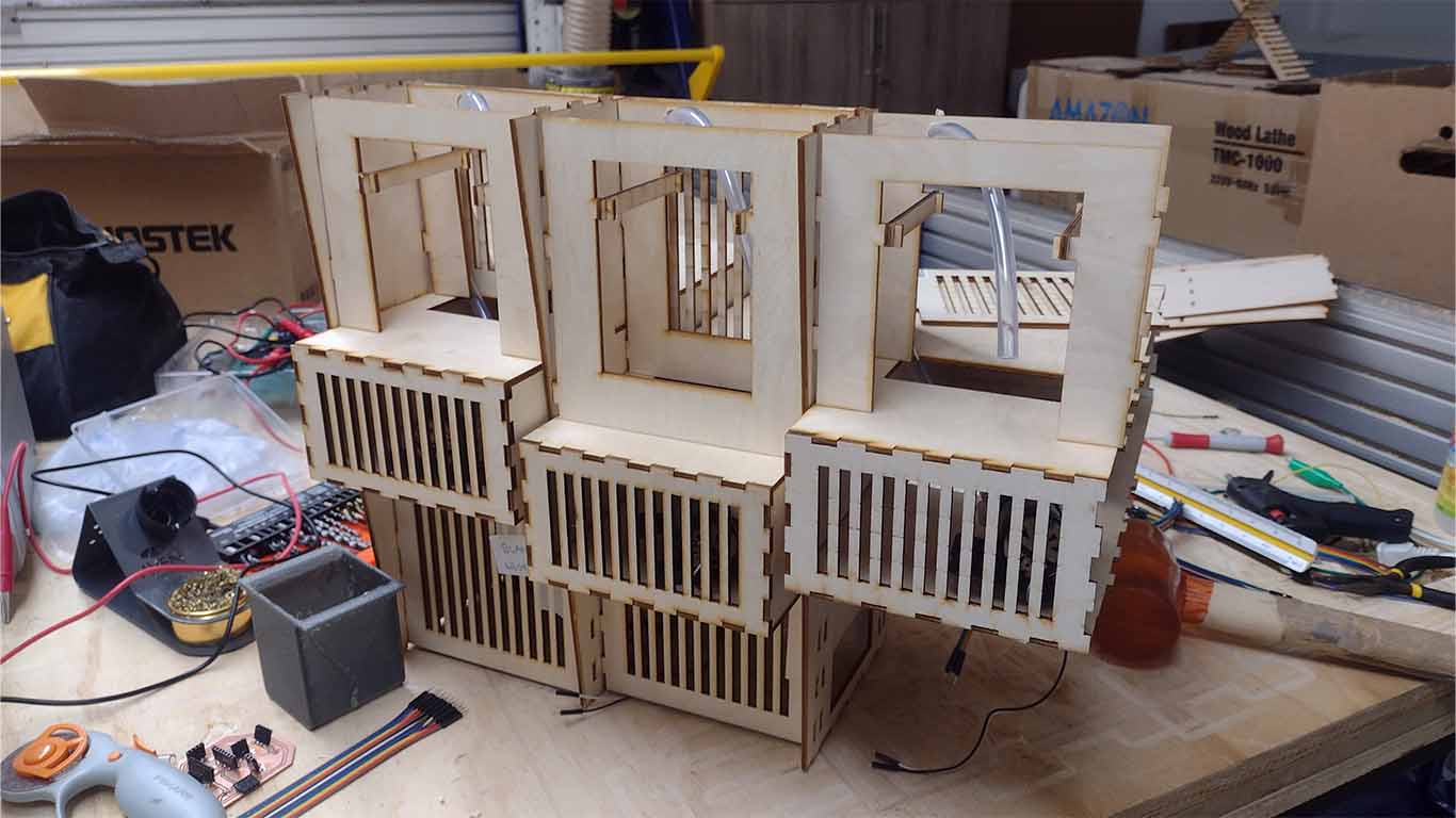
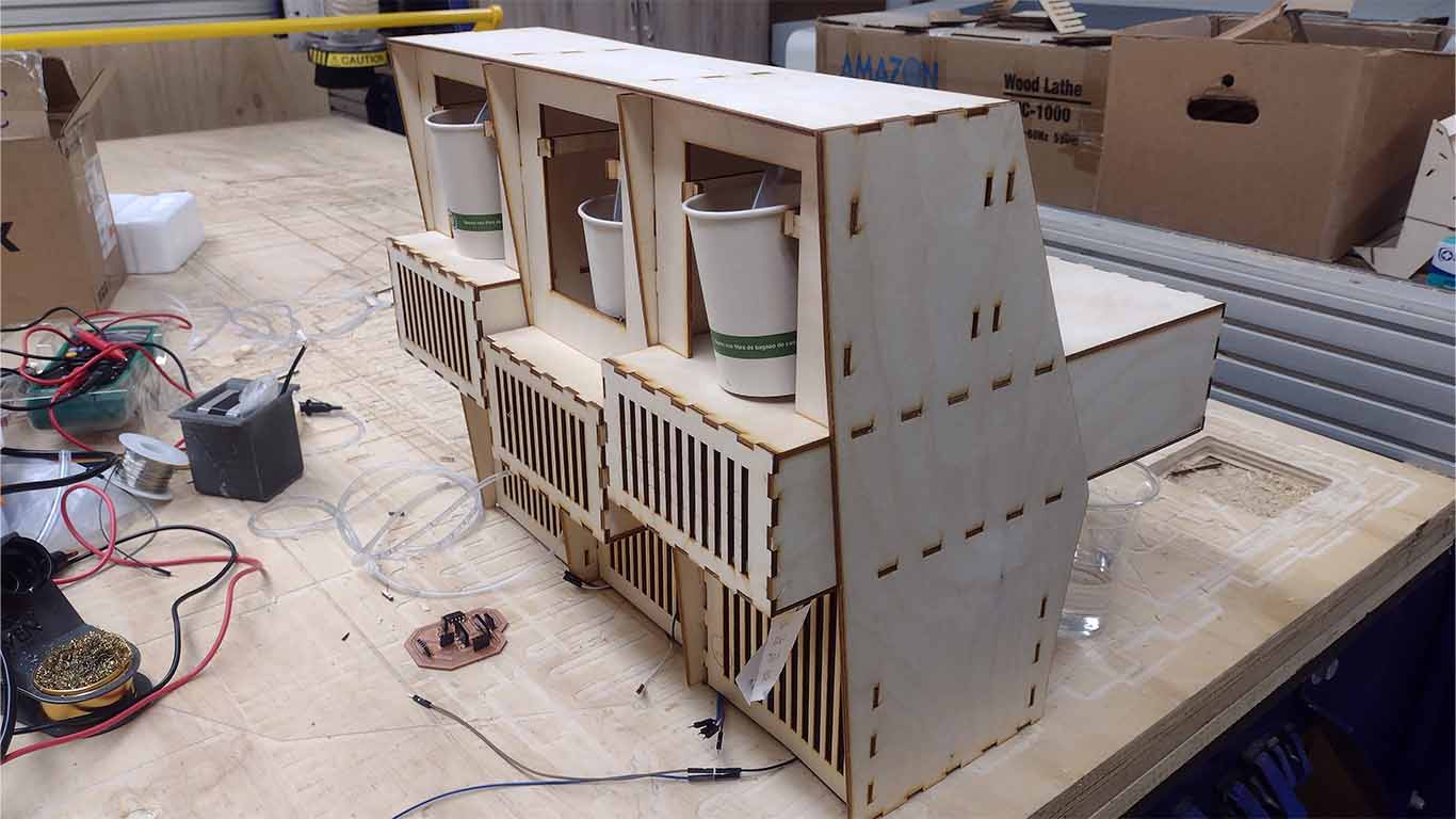
The next day, I began to develop the assembly of the machine's liquid dispenser. First I started on one of the sides, where I began to place the peristaltic pump together with its entire mechanism and I also located the ultrasounds that we used so that I could read the glass that was going to run through the machine.
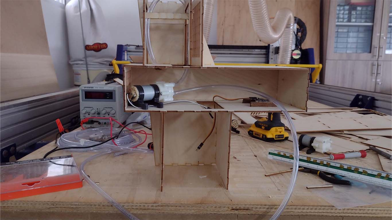
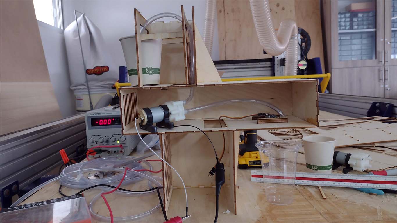
To verify that the entire operation of the liquid dispenser is working correctly, I did a small test with the pump to see if there were leaks or any problems with the mechanism, but everything was fine, here is a video of how it works.
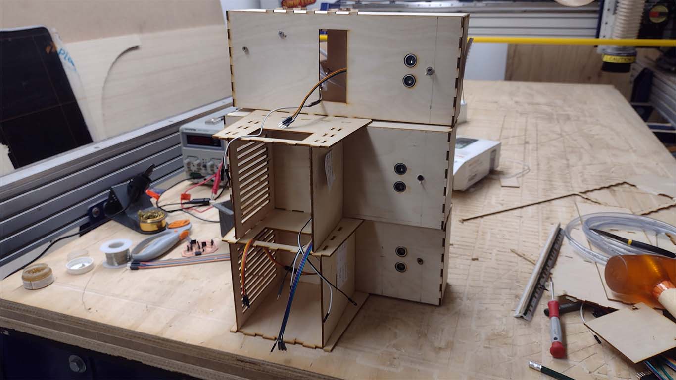
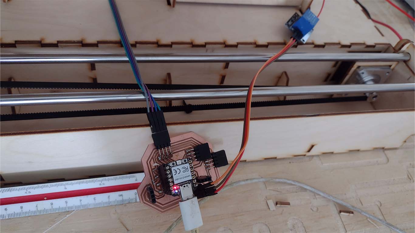
I continued assembling the machine and checking the operation of each sector of the machine. I also began to connect the pump and ultrasound circuits for the electrical part. Here are some photographs of the work.
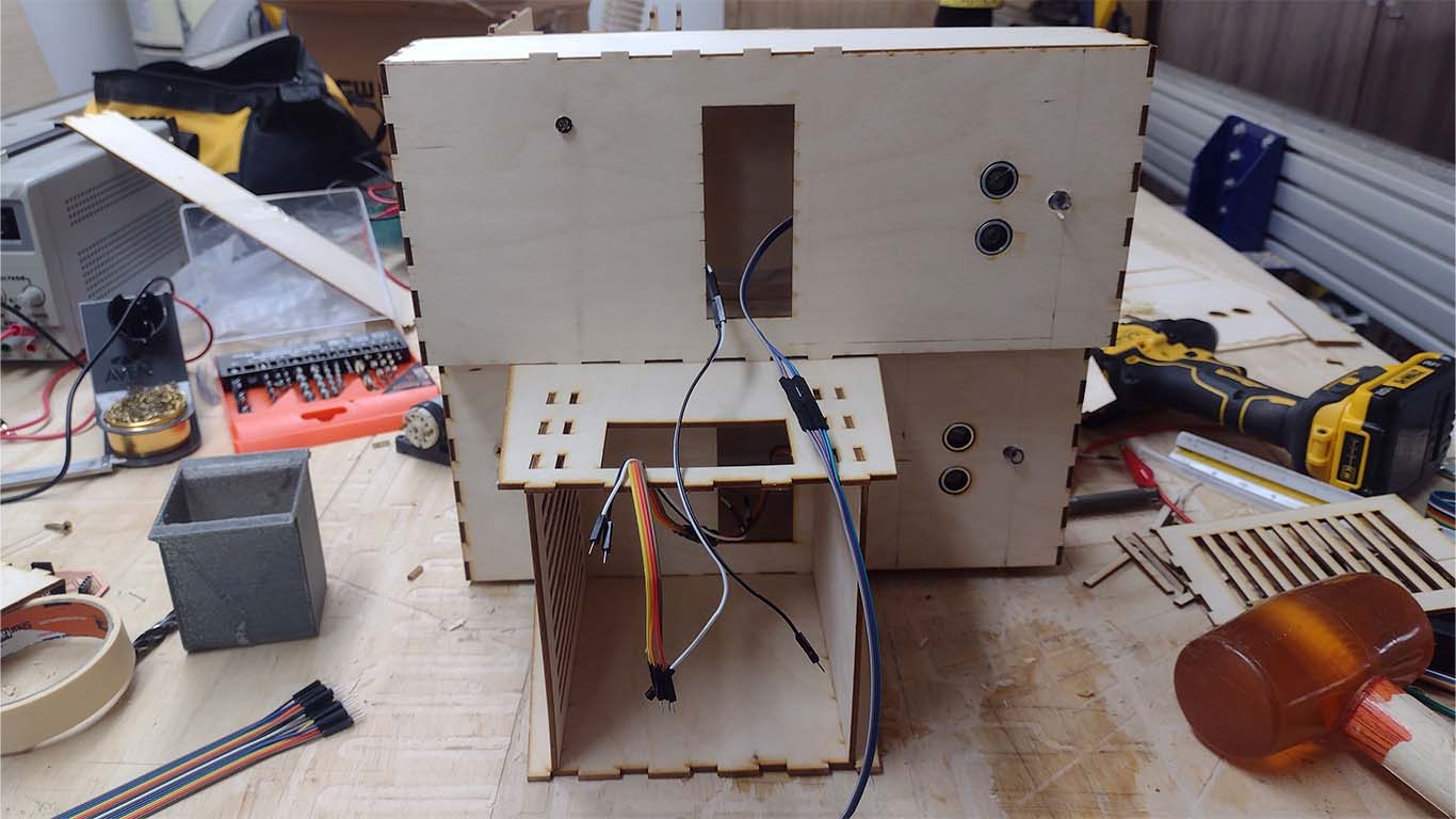
Here you can see what it looked like from the bottom of the machine dispenser, where we have 3 ultrasounds for each liquid, 3 peristaltic pumps along with their electrical connection ready.
Finally, at the end of the day I was able to finish assembling the machine, I really liked the process since I learned many things that we could improve. Now to unify both parts of the machine.
OPERATIONAL TEST
After finishing the entire assembly of the machine, I began to carry out tests with liquids from the dispenser, we have not yet tested with the built-in base to avoid damaging the circuits due to technical failures. Here are some test videos and everything worked very well.
After testing the operation of the dispenser, we moved on to testing the movement of the axis. Here is a video with my colleague Cristian testing and seeing how the mechanism works.
MACHINE DESIGN
For the second part of the group assignment, I participated together with my colleague Cristian in the automation and programming of the machine.
AUTOMATION
First, our colleague in charge of electrical design gave us the board to install and begin the automation of the machine. Here are some photographs of the electrical design connections and automation tests.
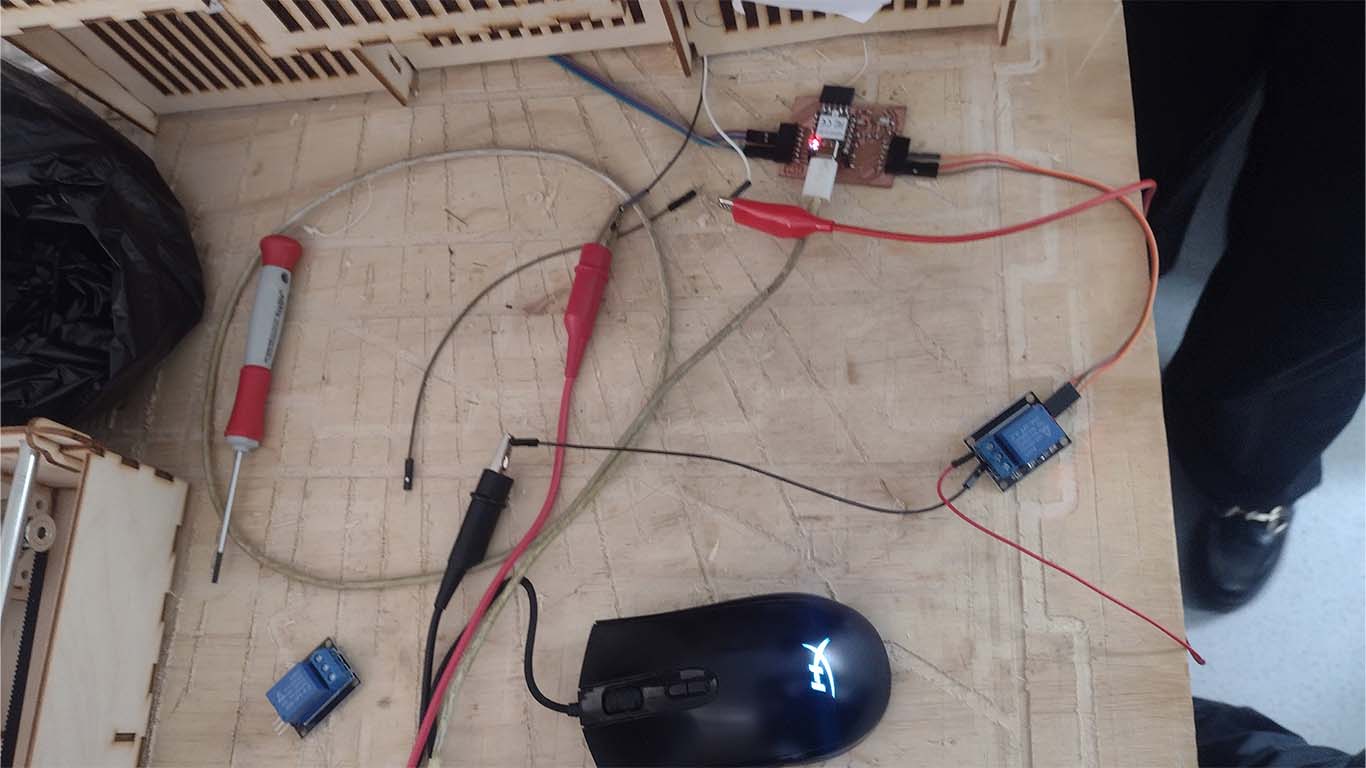
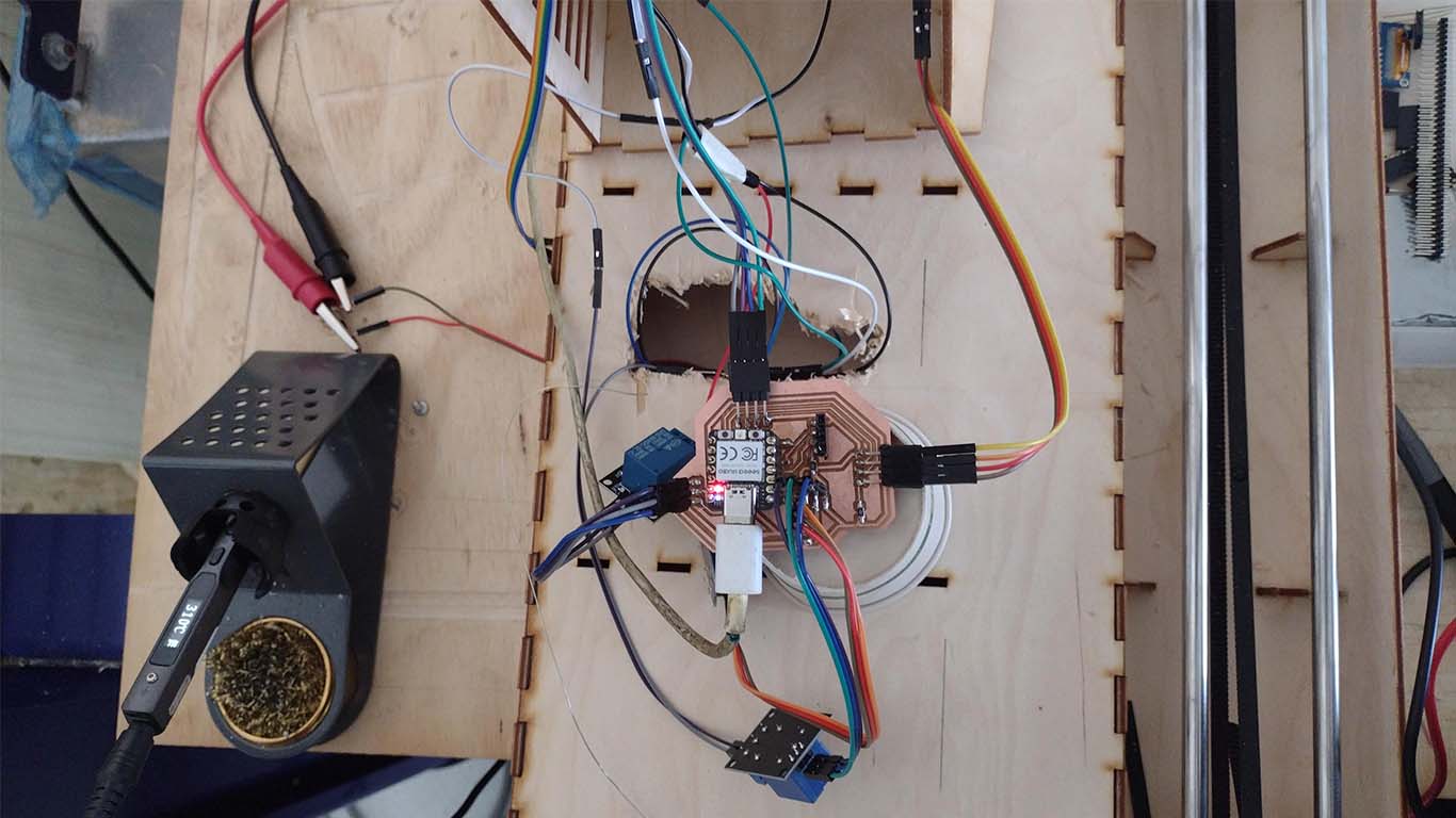
After connecting all the electrical components of the machine, we moved on to automation tests for the general operation of the machine. Here is a video of how we started programming and how it works.
Finally, we started to automate our ultrasonic sensors so we could know if they all worked and had a reading of what we wanted to achieve. Here is a video of the component testing.
FINAL TEST AND RESULT
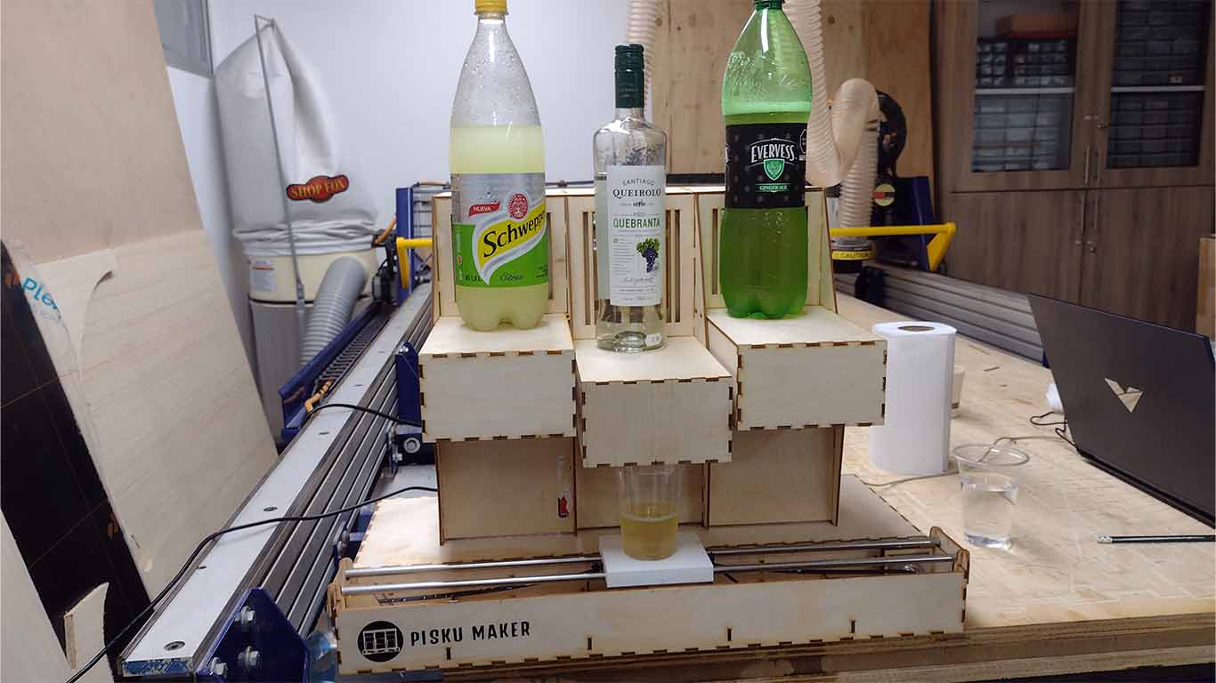
After checking all the operation, automation and programming of the machine, we proceed to carry out the last tests of the machine to achieve the objective.
We were able to observe that the machine worked well but the configuration for synchronization had small errors and the ultrasound reading was not as accurate. We reviewed the programming and automation to achieve the objective.
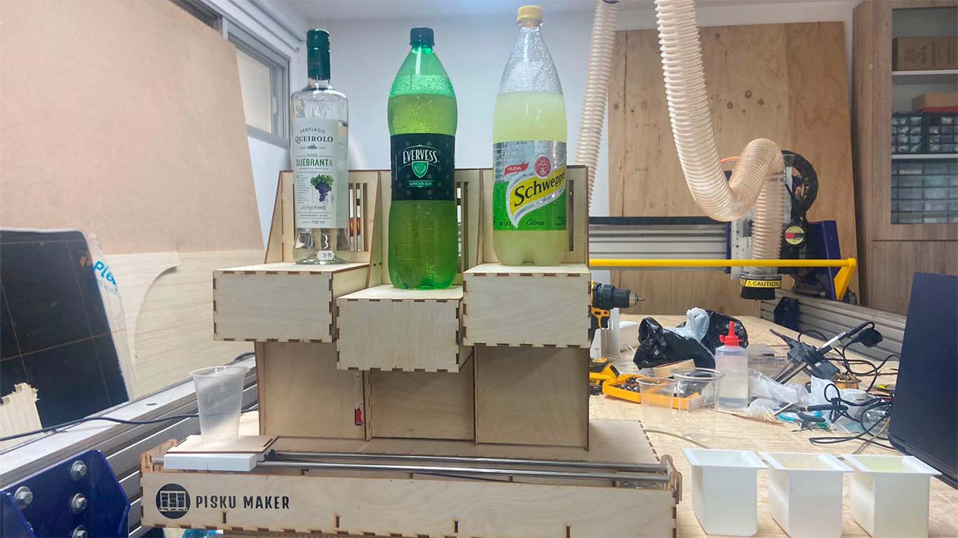
Finally, we were able to achieve synchronization, however we found some limits with the ultrasonic sensors to synchronize the reading well, but the machine was able to work and achieve the objective we wanted. A wonderful adventure, here is the video of how it works and some photos of the machine.
FILES
Here you can download all the files that I have made for the following assignment: