This week's assignment was:
- Compare as many tool options as possible.
- Write an application that interfaces a user with an input &/or output device that you made.
ORGANIZATION
Here I show how I organized myself for this week.
| Wednesday 1th: | Fab Academy classes, organization for the week and review the class. |
|---|---|
| Thursday 2th: | Review and investigation of previous documentation to understand the individual assignment. |
| Friday 3th: | My first steps in programming interfaces and applications in different programs and platforms. |
| Saturday 4th: | Enter GLOBAL OPEN TIME to show my errors and ask some questions about the assignment and develop the group assignment with my colleagues. |
| Sunday: 5th: | Carry out documentation of everything developed. |
| Monday 6th: | Review and correction of documentation. Update and changes for last commit. |
| Tuesday 7th: | Documentation and last commit of the week. |
GROUP ASSIGNMENT
Here I leave the link to go to the group assignments page.
Clic here to visit the WEEK 14 GROUP ASSIGNMENT PAGE
COMPARING MANY TOOL OPTIONS - PYTHON
For the group assignment we divided ourselves individually to investigate 1 tool that Neil recommended to us in class and other tools that our instructors mentioned to us after class. Therefore, in my case I chose PYTHON to learn much more about this tool because I always wanted to discover something more. For this occasion I will focus on TKINTER which is the PYTHON GUI toolkit. Here is my process of getting to know both tools.
INSTALLING PYTHON
To start developing, we need to download PYTHON from the official program page.
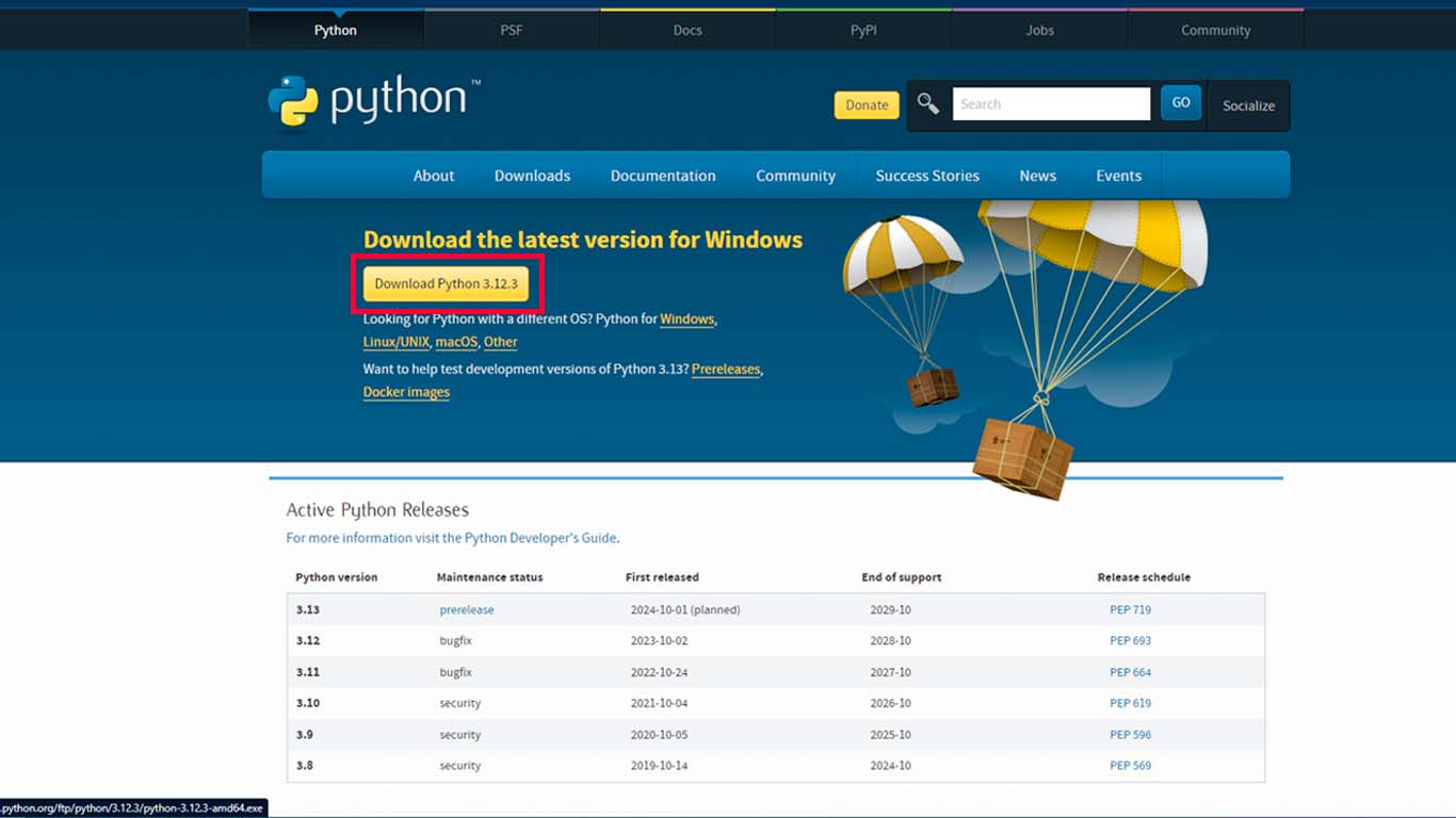
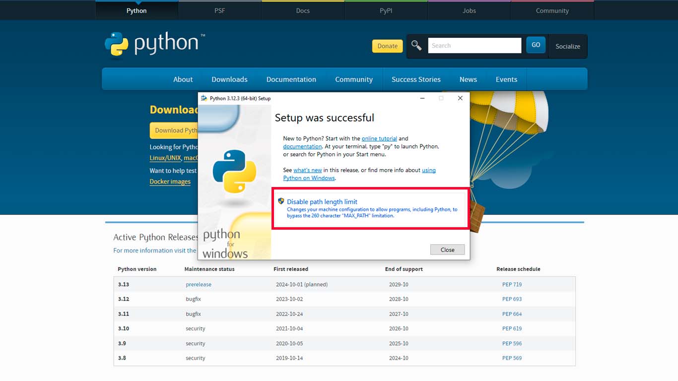
After downloading the installer and clicking on it, the following window will appear.
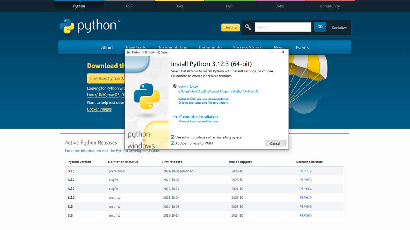
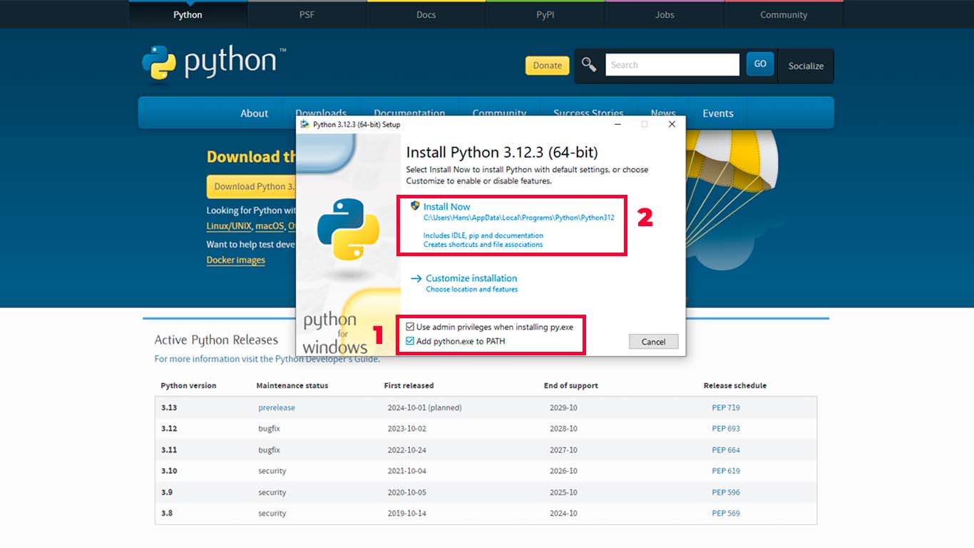
Before clicking "INSTALL" we have to activate the 2 options found at the bottom of the installer. These are important to be able to program in PYTHON and it is advisable to activate it. After activating it, we click install.
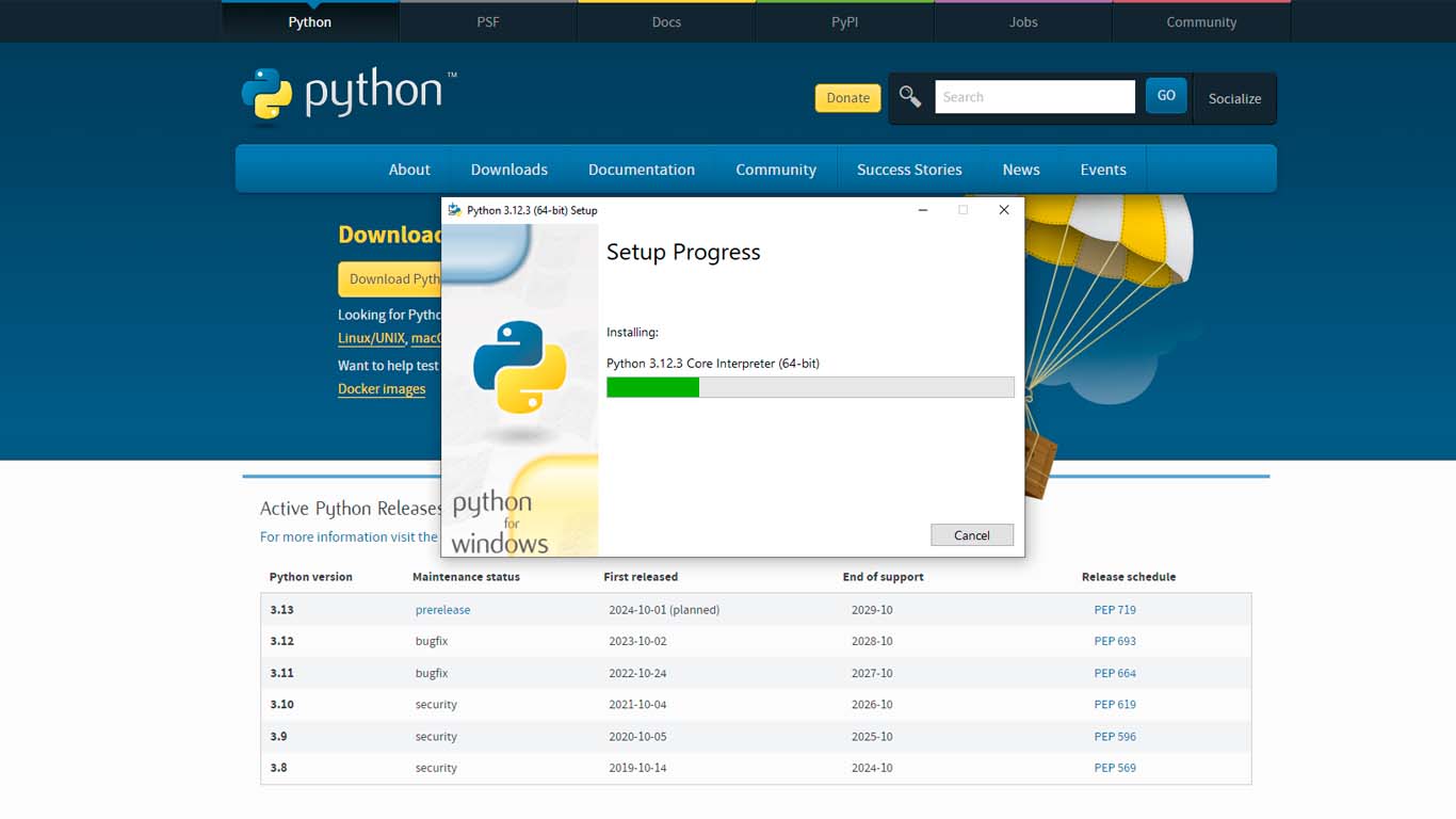
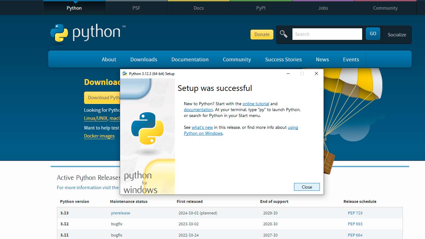
Here we only click on next until we can install it, it is not necessary to make any further modifications to the installation. Just wait for it to install.
Finally, at the end we see an option to disable and we click on it, we accept and finally the PYTHON installation is ready.
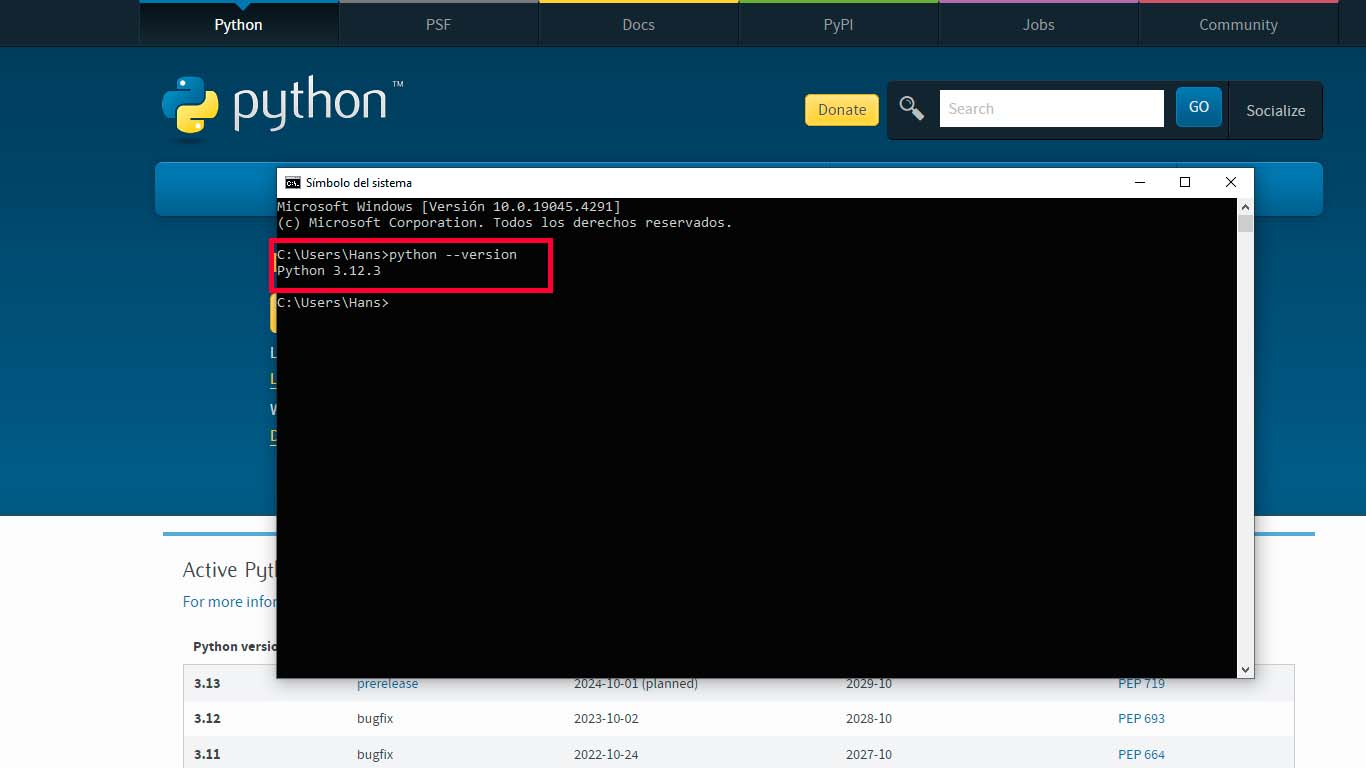
To check that the installation was successful and to know if we have the most up-to-date PYTHON, we open a "SYSTEM PROMPT". And here we write the following:
python --version
Here we should see the name of the program and the version we have, in this case I present version 3.12.3, which is the most up-to-date. With this we verify that it is fine.
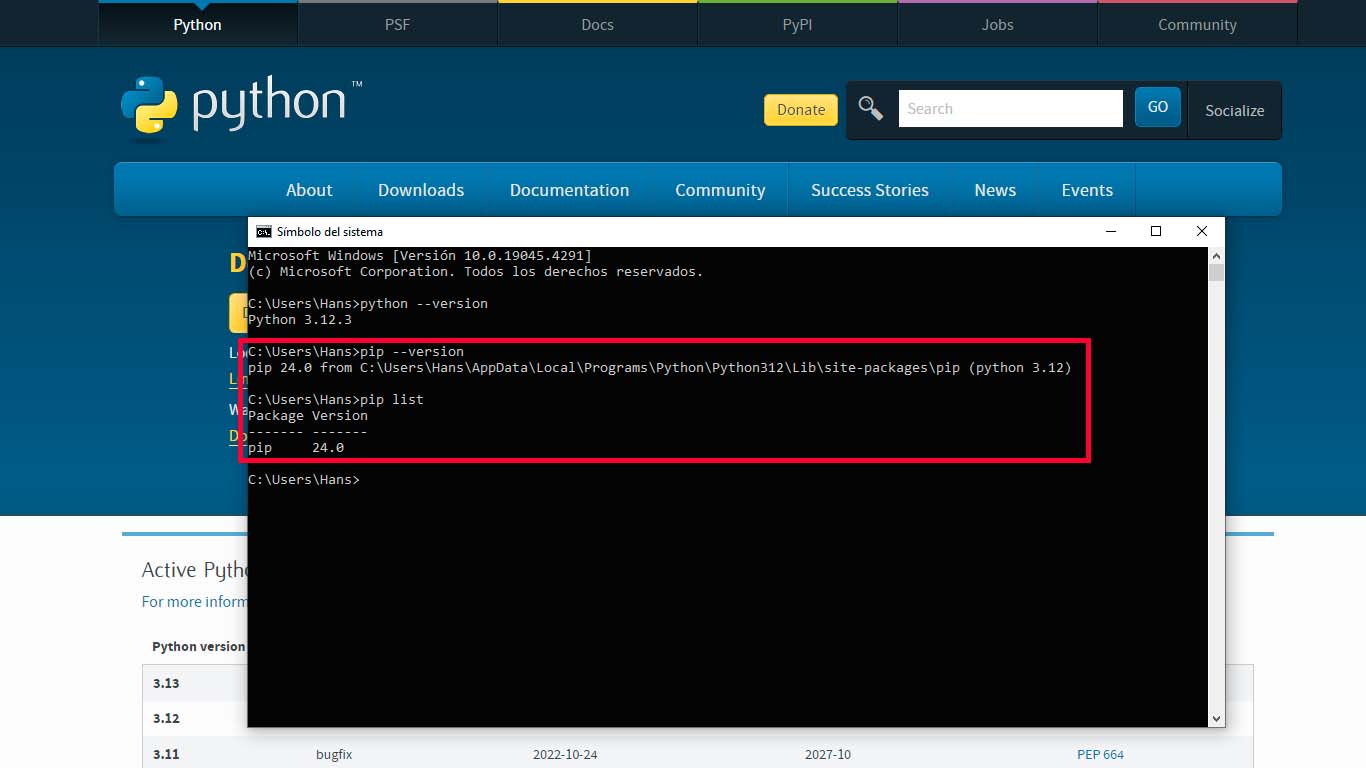
On the other hand, it is also important to check the version and packages that we have in PYTHON, to know this, just by writing these 2 codes that I will leave you below we will obtain information about it. In my case I still don't have any libraries but in the individual part I will show you what libraries can be obtained.
                             pip --version
                             pip list
PYTHON + TKINTER
To start using TKINTER, which is the most used package for creating graphical interfaces in Python. It is an object-oriented layer based on Tcl and TK. We have to open a Python IDLE.
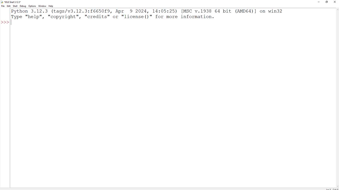
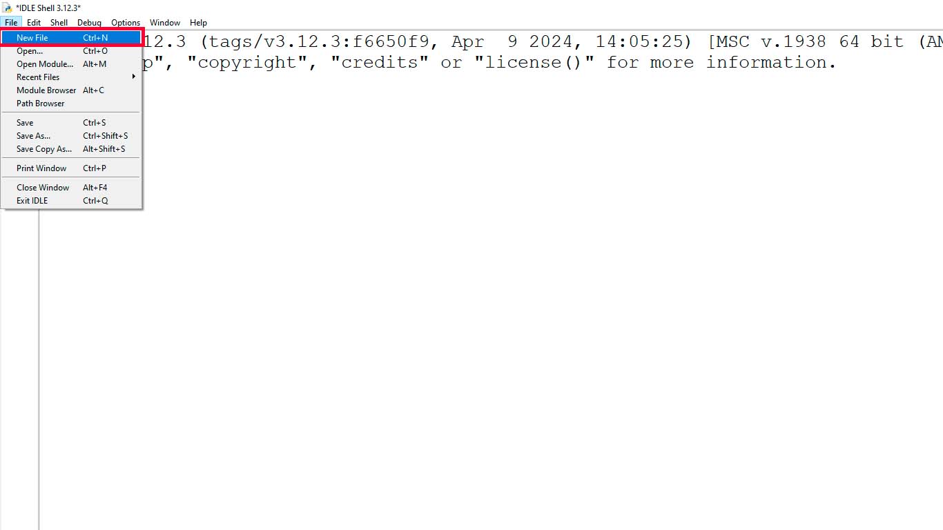
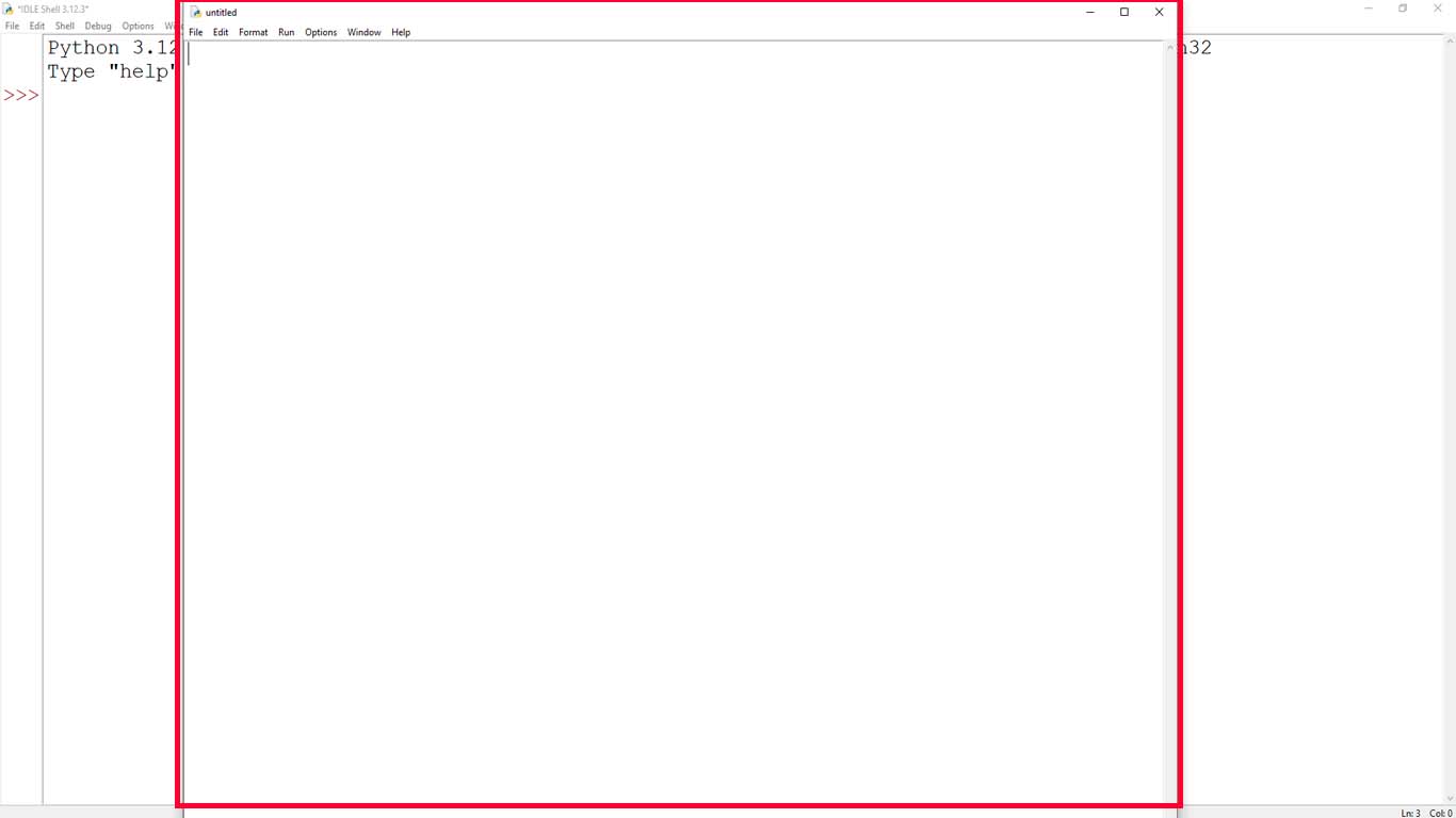
We open a new document at the top of file. And a new screen will open, here we will begin to design our test interface.
After completing the steps, we must import the TKINTER module. You can do it with the following line of code:
import tkinter as tk
Here, we have imported the tkinter module and assigned it to the tk variable. This is done to access the classes and functions provided by Tkinter more conveniently.
Once you've imported Tkinter, you can create a main window or any other widget you want to use. Here is a basic example that creates a main window:
                            import tkinter as tk

                            ventana = tk.Tk()
                            ventana.mainloop()
For this example, we will create a new main window with "tk()" and then write "mainloop()" to allow us to make the window respond to various user events.
Now we will add a title attribute for the window, so that it appears in the title bar. To rename a window in Tkinter, you can use the title attribute of the window instance. The title attribute is used to set the text displayed in the window title bar.
                            import tkinter as tk

                            ventana = tk.Tk()
                            ventana.title("Test Hans Tkinter")
                            ventana.mainloop()
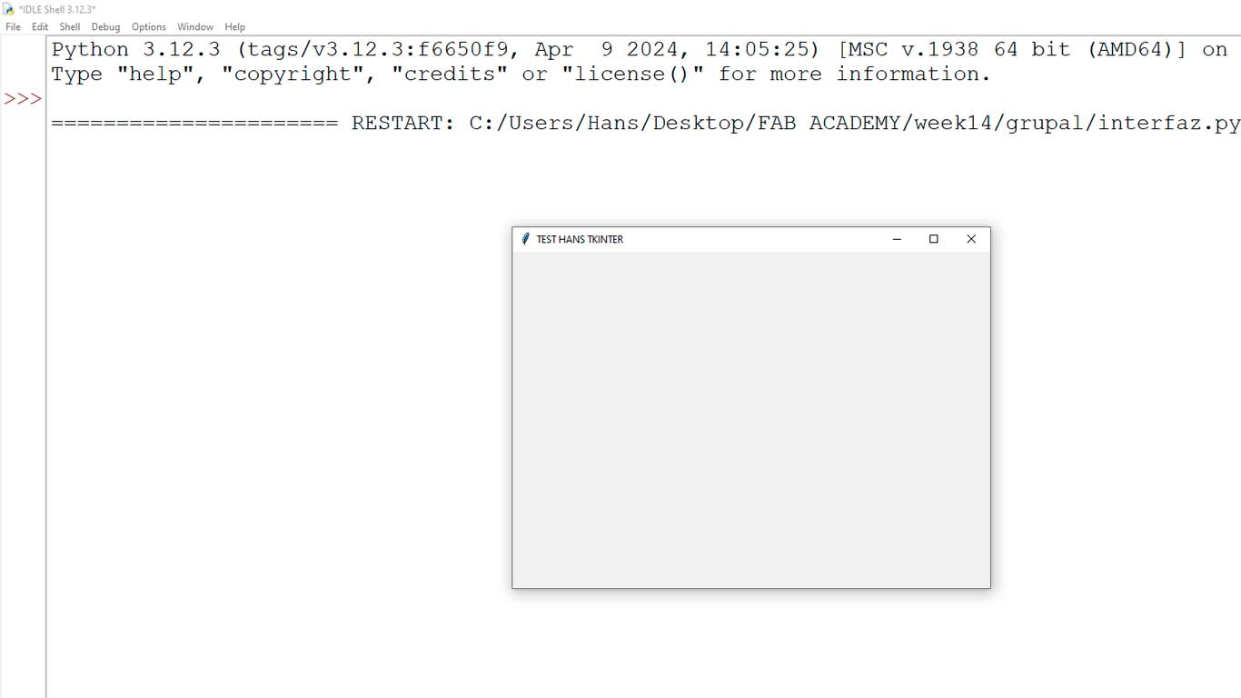
After having all the codes mentioned above, we go to "run" the code in the RUN tab and choose RUN MODULE or simply by pressing F5 on the keyboard.
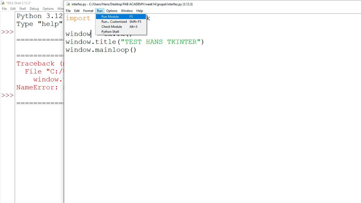
A window will appear where we can see the interface that we are designing and increasing libraries and witgets to achieve our design that we want to apply.
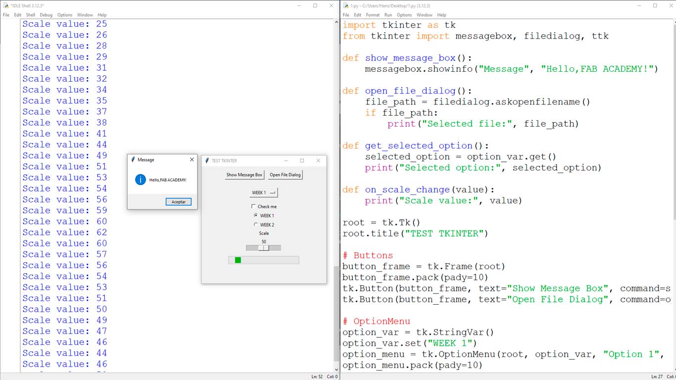
Finally, following some tutorials that I found on the web I was able to use almost all the components of the TKINTER library. Such as message buttons, options menu, list to choose a certain type and graphics. As we can see, they are basic designs that are what we can do and tools that we can use to design our interfaces with TKINTER.
COMPARING MANY TOOL OPTIONS - PROCESSING
INSTALLING PROCESSING
Before starting the installation, we have to know that PROCESSING is an open source programming language and integrated development environment based on Java, easy to use, and that serves as a means for teaching and producing multimedia and interactive digital design projects. . Here the installation process.
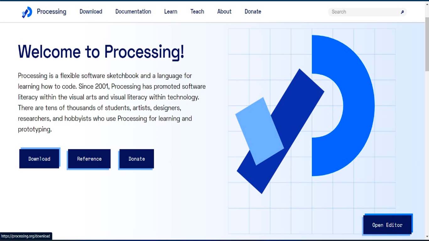
We go to the main PROCESSING page and here we will see different options where we will click on download.
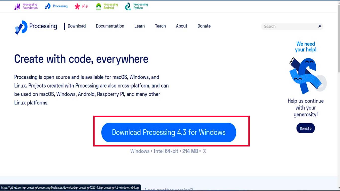
After clicking on it, it will take us to another page where we can see the version we are downloading and we just click on download as shown in the following screenshot.
Finally, we just follow the installation process since it is a very simple program to install and now I will explain my first steps with PROCESSING.
FIRST STEPS WITH PROCESSING
After installing the program and when starting. We can see that its work area is similar to that of the ARDUINO IDE. It seems to me that it has a very easy to understand and friendly interface for anyone who is starting with interface programming.
You can begin to understand the codes and by clicking on the "PLAY" symbol we can see how our interface design that we want to develop is looking.
To start with the use of processing and the tools it offers us, I was guided by the class that instructor Michael Hurtado gave us. He helped us a lot to understand the program and explained to us how we could understand each tool, what it is for and how we can use it. Here I achieved a little of what he mentioned in the class. Thank you very much teacher for teaching and sharing your knowledge.
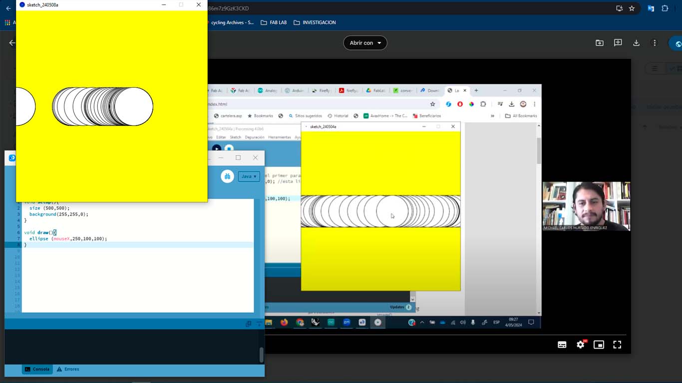
Then, by changing some settings I was able to make a small change to the template that teacher Michael left us. Here I show you how I was able to learn to modify the codes and do creative things.
                                void setup(){
                                    size (500,500);
                                    background(255,255,0);
                                  }

                                  void draw(){
                                    fill(random(255), random(255), random(255));
                                    ellipse (mouseX,mouseY,100,100);
                                  }
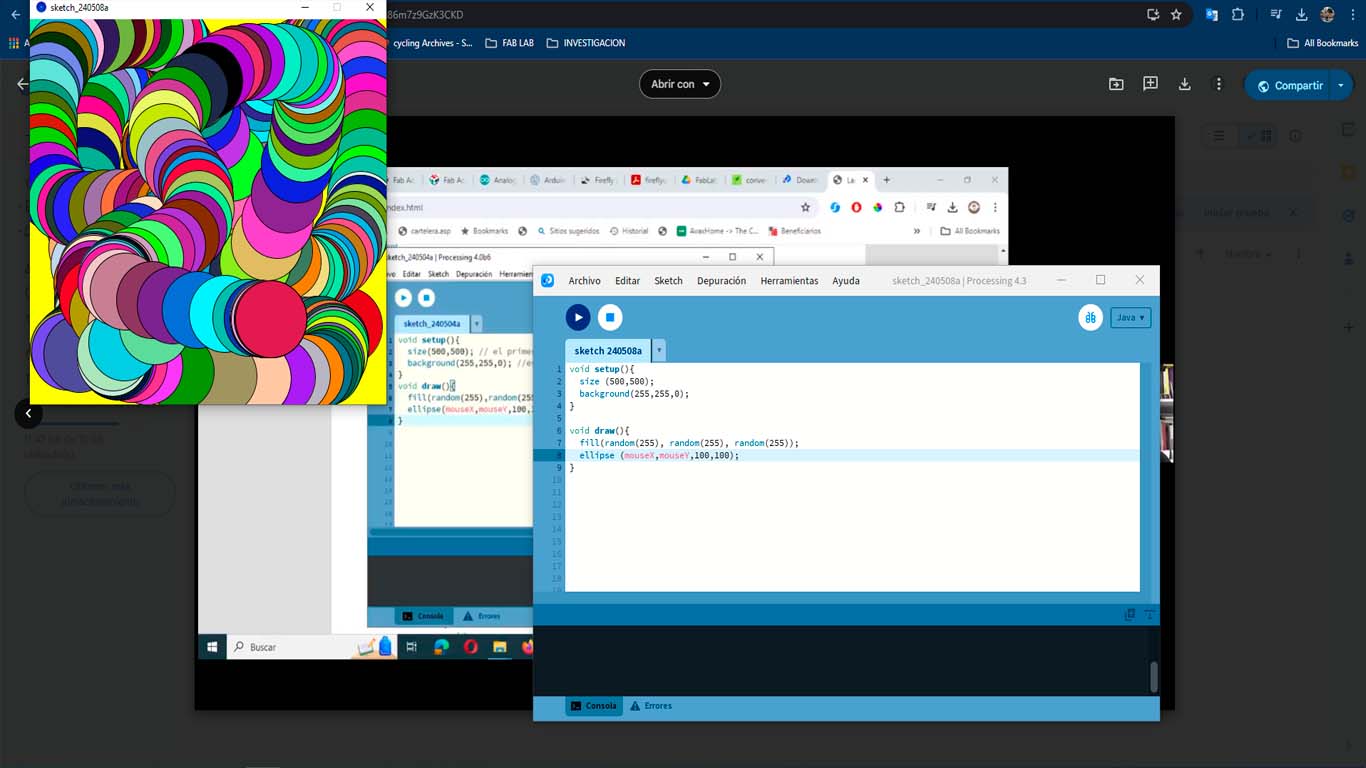
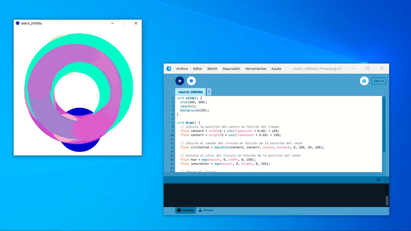
Finally, after being able to understand many tools, I was able to make a small canvas with the basic tools that processing presents to us. Here is a screenshot of what I achieved.
                                void setup() {
                                    size(500, 500);
                                    smooth();
                                    background(255);
                                  }

                                  void draw() {
                                    // Calculate the center position based on time
                                    float centerX = width/2 + sin(frameCount * 0.05) * 150;
                                    float centerY = height/2 + cos(frameCount * 0.05) * 150;

                                    // Calculate the size of the circle based on mouse position
                                    float circleSize = map(dist(centerX, centerY, mouseX, mouseY), 0, 250, 20, 100);

                                    // Calculate the color of the circle based on mouse position
                                    float hue = map(mouseX, 0, width, 0, 255);
                                    float saturation = map(mouseY, 0, height, 0, 255);

                                    // Draw the circle
                                    noStroke();
                                    fill(hue, saturation, 200);
                                    ellipse(centerX, centerY, circleSize, circleSize);
                                  }
To conclude with Processing, I could comment that the program is very easy to use for those who have never developed interfaces. It seems to me to be a friendly program that its programming helps us understand each tool or software we are using. For the individual assignment I will use both programs, that is, PYTHON and PROCESSING, but I will focus more on PROCESSING because of the way in which artistic things can be achieved in interfaces.
VIRTUAL GROUP WORK AND CONCLUSION
VIRTUAL GROUP WORK
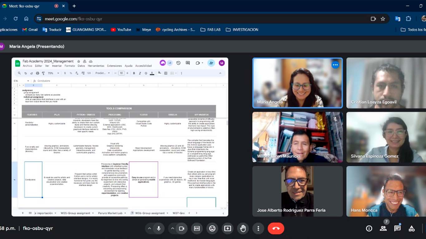
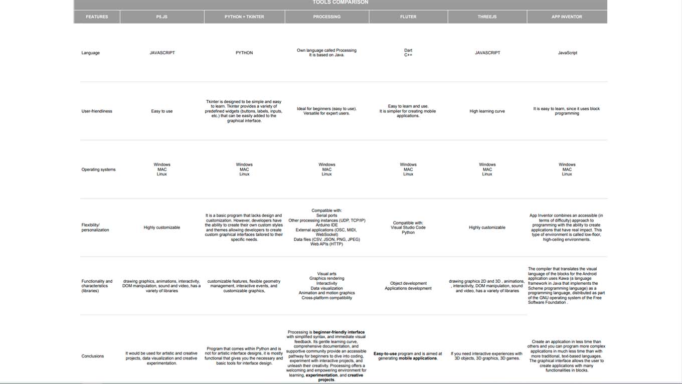
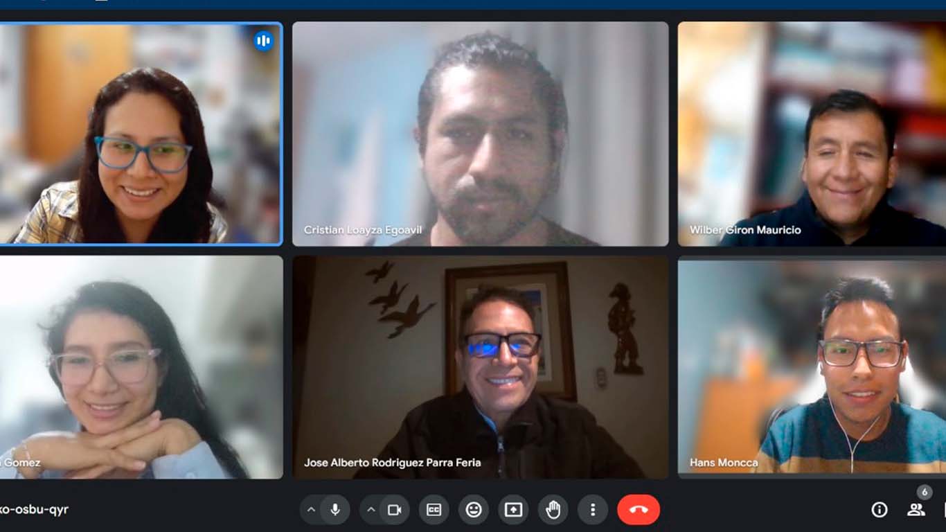
To develop the group work, each member of our node chose a tool or program that was going to investigate its uses, characteristics and give a conclusion for its use and manage to develop this week's assignment. Finally, we meet virtually to show our work and give our conclusions. Here is a screenshot developing our comparative table.
CONCLUSION
After exploring and listening to my colleagues about all the programs and tools they could research, we concluded that PROCESSING is one of the simplest tools for the assignment. Many tried other applications but had problems with the communication between the microcontroller and the interface. Therefore, we were able to conclude that PROCESSING presents a basic programming that is possible to develop many innovative interfaces. For my part, I can conclude that TKINTER is also a simple tool but is limited when it comes to achieving artistic designs unlike PROCESSING. It can be used to achieve simple interfaces such as buttons, images or lists to choose from. It has a very basic design but I understood that with liberias it could be improved but I think PROCESSING is a step forward both in the product and in the way of using the program.
Here is the link to see our conclusions: DOWNLOAD PDF FILE
Finally, I found out that this is the last FAB ACADEMY group assignment. I just realized how quickly the weeks went by and I was very pleased to meet wonderful people who shared moments that will remain to remember.
SUPPORT AND FEEDBACK
GLOBAL OPEN TIME
For this assignment I was able to join at the end of the OPEN GLOBAL TIME meeting, where Adrian, Rico and the colleagues are always explaining and supporting us to achieve the assignment. Another week that I can't have a capture with them but I was able to resolve some doubts I had about the assignment. Thank you very much and especially to teacher Adrian, who is always supporting me week after week.
MEETING WITH INSTRUCTOR
To complete this week's assignment, I met with teacher Ulises to better understand the Python program since it was the first time I had interacted with the program and I also had some problems programming. Thanks to him, I was able to understand the program better and one week more grateful to him for sharing his knowledge.
INDIVIDUAL ASSIGNMENT
LED WITH ARDUINO IDE + PYTHON + TKINTER + MQTT
For this individual assignment I am going to start with an interface developed in PYTHON and TKINTER where the idea is to turn on an LED on my board using 2 buttons and the communication protocol is MQTTX. I am using the XIAO ESP32 C3 connected via WIFI and here the process and result.
Before starting the programming we have to install the PAHO MQTT for PYTHON communication with MQTTX, this is what allows communication. Here the installation process.
In my case I will install it by SYSTEM SYMBOL - CMD in Windows, where we will write the following text that I leave below.
pip install paho-mqtt
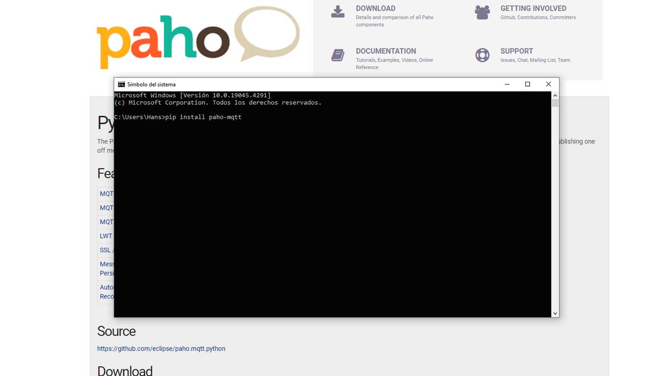
Pressing ENTER will install the PAHO MQTT.
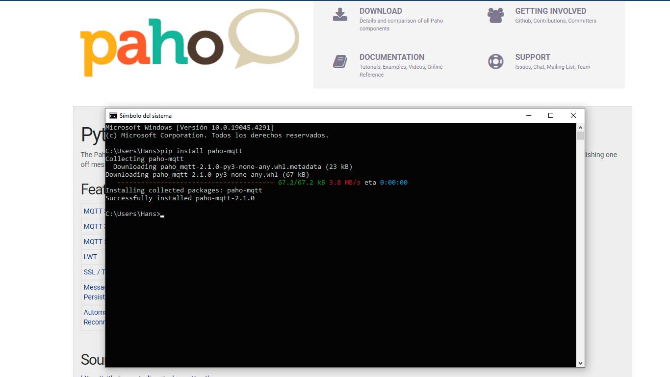
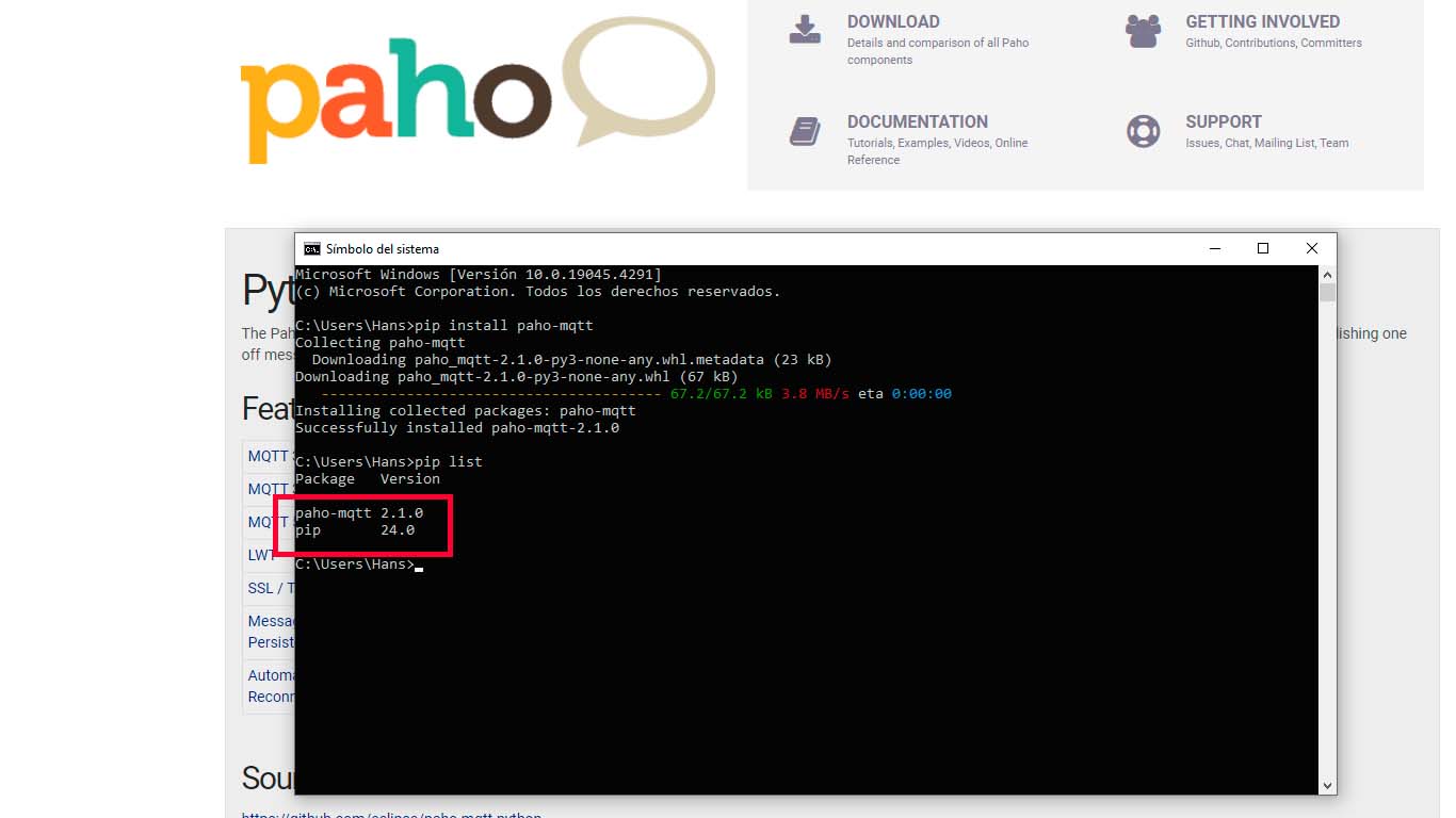
To verify that the PAHO MQTTX package was installed correctly, we can check by placing the following text that I leave below and we can see that it was installed.
pip list
After installing and verifying that everything is installed very well, we begin programming the ARDUINO IDE and PYTHON to achieve communication via MQTTX.
PROGRAMMING
For programming, we will do it in both programs, that is, ARDUINO IDE and PYTHON to achieve communication through the MQTTX protocol and we can see that the LED lights up or not, below I leave the programming codes for each one.
PYTHON PROGRAMMING
                              import tkinter as tk
                              from tkinter import ttk
                              import paho.mqtt.client as mqtt

                              broker_address = "broker.emqx.io"
                              topic = "week14/test"

                              def on_connect(client, userdata, flags, rc):
                                  print("Conectado con el código de resultado: " + str(rc))
                                  client.subscribe(topic)

                              def on_message(client, userdata, message):
                                  print("Mensaje recibido:", str(message.payload.decode("utf-8")))

                              def encender_led():
                                  client.publish(topic, "1")

                              def apagar_led():
                                  client.publish(topic, "0")

                              client = mqtt.Client()
                              client.on_connect = on_connect
                              client.on_message = on_message
                              client.connect(broker_address, 1883, 60)
                              client.loop_start()

                              root = tk.Tk()
                              root.title("HM BOARD LED")

                              # Estilo para los botones
                              style = ttk.Style()
                              style.configure('TButton', font=('calibri', 10, 'bold'), foreground='black', background='lightgray', padding=5)
                              style.map('TButton', foreground=[('active', 'black')], background=[('active', 'gray')])

                              # Creación de los botones
                              encender_button = ttk.Button(root, text="TURN ON", command=encender_led)
                              encender_button.pack(pady=10)

                              apagar_button = ttk.Button(root, text="TURN OFF", command=apagar_led)
                              apagar_button.pack(pady=10)

                              root.mainloop()
ARDUINO IDE PROGRAMMING
                            #include WiFi.h
                            #include PubSubClient.h

                              const char* ssid = "...."; // ID of your wifi
                              const char* password = "...."; // Password of wifi
                              const char* mqtt_server = "broker.emqx.io"; // SERVER OF MQTT
                              const int mqtt_port = 1883;

                              WiFiClient espClient;
                              PubSubClient client(espClient);

                              const char* topic = "week14/test";
                              const int switchPin = D2;  // Pin of XIAO ESP32-C3
                              const int ledPin = D3;    // Pin of XIAO ESP32-C3

                              void setup_wifi() {
                                delay(10);
                                Serial.println();
                                Serial.print("Conectando a ");
                                Serial.println(ssid);

                                WiFi.begin(ssid, password);

                                while (WiFi.status() != WL_CONNECTED) {
                                  delay(500);
                                  Serial.print(".");
                                }

                                Serial.println("");
                                Serial.println("Conexión WiFi establecida");
                                Serial.println("Dirección IP: ");
                                Serial.println(WiFi.localIP());
                              }

                              void callback(char* topic, byte* payload, unsigned int length) {
                                Serial.print("Mensaje recibido [");
                                Serial.print(topic);
                                Serial.print("] ");
                                for (int i = 0; i < length; i++) {
                                  Serial.print((char)payload[i]);
                                }
                                Serial.println();

                                if ((char)payload[0] == '1') {
                                  digitalWrite(ledPin, HIGH);
                                } else if ((char)payload[0] == '0') {
                                  digitalWrite(ledPin, LOW);
                                }
                              }

                              void reconnect() {
                                while (!client.connected()) {
                                  Serial.print("Intentando conexión MQTT...");
                                  if (client.connect("arduinoClient")) {
                                    Serial.println("conectado");
                                    client.subscribe(topic);
                                  } else {
                                    Serial.print("falló, rc=");
                                    Serial.print(client.state());
                                    Serial.println(" intentando nuevamente en 5 segundos");
                                    delay(5000);
                                  }
                                }
                              }

                              void setup() {
                                pinMode(ledPin, OUTPUT);
                                pinMode(switchPin, INPUT_PULLUP);
                                Serial.begin(115200);
                                setup_wifi();
                                client.setServer(mqtt_server, mqtt_port);
                                client.setCallback(callback);
                              }

                              void loop() {
                                if (!client.connected()) {
                                  reconnect();
                                }
                                client.loop();

                                static bool lastSwitchState = HIGH;
                                bool switchState = digitalRead(switchPin);

                                if (switchState == LOW && lastSwitchState == HIGH) {
                                  client.publish(topic, "1");
                                  delay(500);  // Debouncing
                                } else if (switchState == HIGH && lastSwitchState == LOW) {
                                  client.publish(topic, "0");
                                  delay(500);  // Debouncing
                                }

                                lastSwitchState = switchState;
                              }
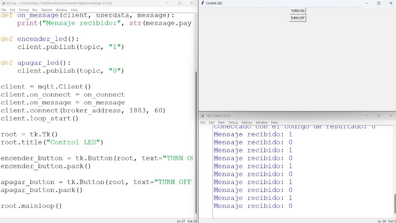
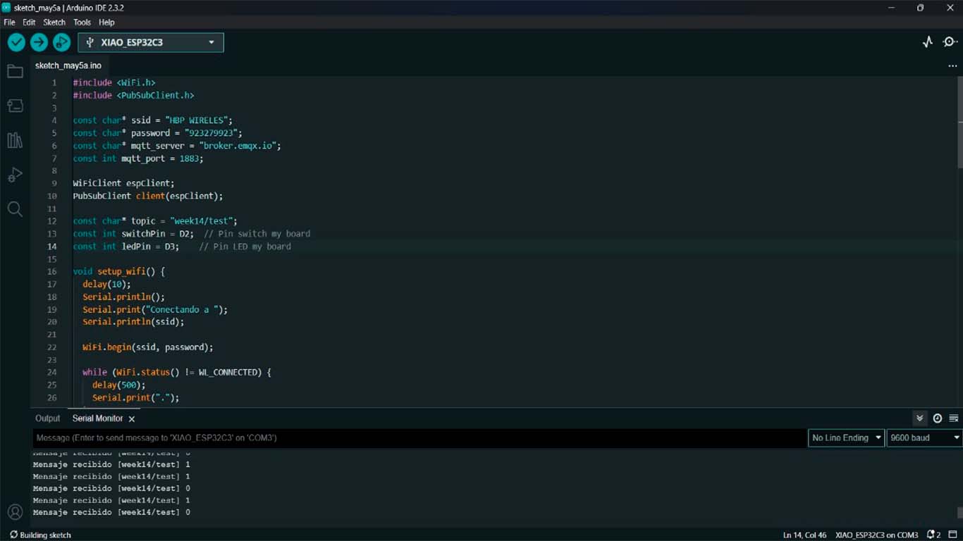
Here we can see how in serial the XIAO ESP32 C3 begins to read the messages that PYTHON sends when we press the LED on and off button.
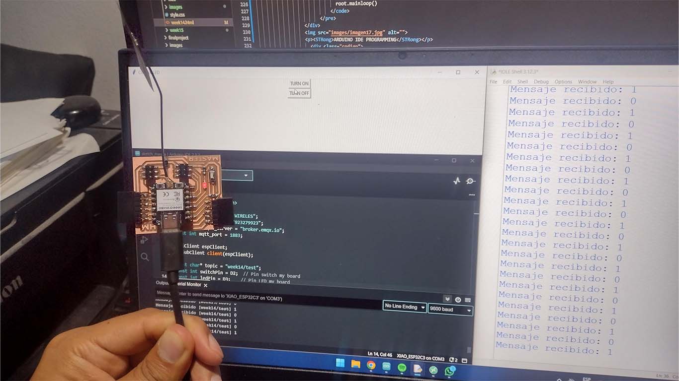
RESULT
As a result, we were able to obtain that from the interface created with the TKINTER library in PYTHON we could turn the LED on and off using MQTTX and ARDUINO IDE. Here is a screenshot and a video of how this first result was achieved.
PROCESSING + INPUTS
PROCESSING + ULTRASONIC
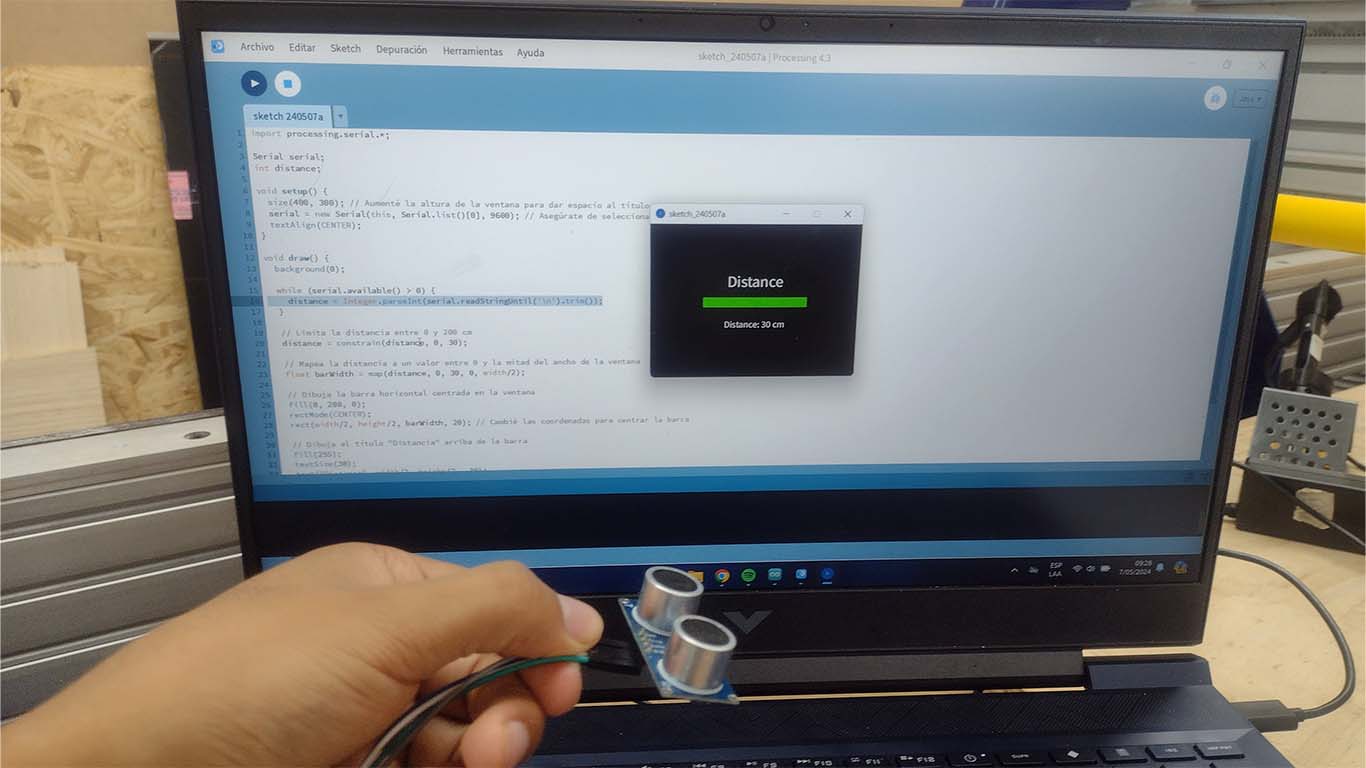
Now I wanted to try PROCESSING with some inputs and outputs that I developed in previous weeks of the FAB ACADEMY. The idea was to create a programming interface for each of them. I found PROCESSING super simple and very useful since it is very basic and at the same time gives us many tools to achieve incredible things. Here the process with an ultrasound sensor.
To start with something simple, we will try a simple interface where the PROCESSING gives us the distance that the ultrasound is measuring and shows us with a green bar that varies according to the distance that the input is measuring. Here the process.
PROGRAMMING
For programming, I first started by opening the ARDUINO IDE and programming the ultrasound. After that, I programmed the COMPRESSING so that through serial it could show me the values that the ultrasound was reflecting. Here the code in both programs.
ARDUINO IDE PROGRAMMING
                            #define TRIG_PIN 3
                            #define ECHO_PIN 4

                            void setup() {
                            Serial.begin(9600);
                            pinMode(TRIG_PIN, OUTPUT);
                            pinMode(ECHO_PIN, INPUT);
                            }

                            void loop() {
                            long duration, distance;

                            // Clear the TRIG_PIN
                            digitalWrite(TRIG_PIN, LOW);
                            delayMicroseconds(2);

                            // Send a pulse to TRIG_PIN
                            digitalWrite(TRIG_PIN, HIGH);
                            delayMicroseconds(10);
                            digitalWrite(TRIG_PIN, LOW);

                            // Measure the duration of the pulse received on ECHO_PIN
                            duration = pulseIn(ECHO_PIN, HIGH);

                            // Convert the duration into distance
                            distance = (duration * 0.0343) / 2;

                            // Print the distance to Serial Monitor
                            Serial.print(distance);
                            Serial.println();

                            delay(1000); // Wait for a second before taking the next measurement
                            }
PROCESSING PROGRAMMING
                                import processing.serial.*;

                                Serial serial;
                                int distance;

                                void setup() {
                                size(400, 300); // Increased window height to accommodate title
                                serial = new Serial(this, Serial.list()[0], 9600); // Make sure to select the correct serial port
                                textAlign(CENTER);
                                }

                                void draw() {
                                background(0);

                                while (serial.available() > 0) {
                                    distance = Integer.parseInt(serial.readStringUntil('\n').trim());
                                }

                                // Limit distance between 0 and 200 cm
                                distance = constrain(distance, 0, 30);

                                // Map distance to a value between 0 and half the window width
                                float barWidth = map(distance, 0, 30, 0, width/2);

                                // Draw horizontal bar centered in the window
                                fill(0, 200, 0);
                                rectMode(CENTER);
                                rect(width/2, height/2, barWidth, 20); // Changed coordinates to center the bar

                                // Draw title "Distance" above the bar
                                fill(255);
                                textSize(30);
                                text("Distance", width/2, height/2 - 30);

                                fill(255);
                                textSize(18);
                                text("Distance: " + distance + " cm", width/2, height/2 + 50);
                                }
RESULT
As a result I was able to obtain that the sensor reading works in the designed interface. We can see that through SERIAL we can obtain the information read by the sensor and this is represented in the designed PROCESSING interface. Here is a screenshot and a video of how the first interface design was achieved in PROCESSING.
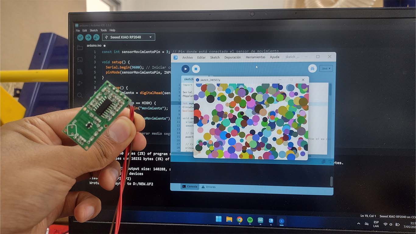
PROCESSING + MOTION SENSOR
Then I wanted to increase the programming difficulty and now I wanted to design an interface for the motion sensor. I reviewed some documentation and the one I liked the most was from Maestro Adrian, who developed an idea with circle movements in PROCESSING. Upon seeing it, I made my own interface with the inspiration he made in his documentation. Here I leave the link to his documentation where you can see how he developed his interface. I'm trying to do something similar with the motion sensor. Here the process.
LINK TO ADRIAN'S DOCUMENTATION
PROGRAMMING
To program the sensor, I first did a functional test before starting to work with both programs. After seeing that the sensor was reading, I programmed it in PIN 3 of the XIAO RP2040 and then in PROCESSING I added the SERIAL so that it could detect when it was reading movement or not. Here are the programming codes for both programs.
ARDUINO IDE PROGRAMMING
                            const int motionSensorPin = 3; // Pin where the motion sensor is connected

                            void setup() {
                            Serial.begin(9600); // Start serial communication at 9600 baud
                            pinMode(motionSensorPin, INPUT); // Configure sensor pin as input
                            }

                            void loop() {
                            int motion = digitalRead(motionSensorPin); // Read the state of the motion sensor pin

                            if (motion == HIGH) {
                                Serial.println("motion");
                            } else {
                                Serial.println("noMotion");
                            }

                            delay(500); // Wait half a second before checking again
                            }
PROCESSING PROGRAMMING
                                import processing.serial.*;

                                Serial serialPort;
                                PApplet mySketch;

                                int numCircles = 300; // Number of circles
                                Circle[] circles; // Array to store circles
                                boolean motionDetected = false; // Motion state

                                void setup() {
                                  size(800, 600); // Canvas size
                                  smooth(); // Enable edge smoothing

                                  // Initialize serial communication
                                  serialPort = new Serial(this, Serial.list()[0], 9600); // Change index if necessary

                                  // Create circles
                                  circles = new Circle[numCircles];
                                  for (int i = 0; i < numCircles; i++) {
                                    circles[i] = new Circle(random(width), random(height), random(20, 50));
                                  }

                                  // Start PApplet class
                                  mySketch = new PApplet();
                                }

                                void draw() {
                                  background(255); // White background

                                  // Update and display circles
                                  for (int i = 0; i < numCircles; i++) {
                                    if (motionDetected) {
                                      circles[i].moveRandomly();
                                      circles[i].changeColorRandomly();
                                    }
                                    circles[i].display();
                                  }
                                }

                                void serialEvent(Serial port) {
                                  String message = serialPort.readStringUntil('\n');
                                  if (message != null) {
                                    message = trim(message);
                                    if (message.equals("motion")) {
                                      motionDetected = true;
                                    } else if (message.equals("noMotion")) {
                                      motionDetected = false;
                                    }
                                  }
                                }

                                // Class to represent circles
                                class Circle {
                                  float x, y; // Position
                                  float diameter; // Diameter
                                  float velocityX, velocityY; // Velocities
                                  int colorR, colorG, colorB; // Color

                                  Circle(float x, float y, float diameter) {
                                    this.x = x;
                                    this.y = y;
                                    this.diameter = diameter;
                                    this.velocityX = random(-2, 2);
                                    this.velocityY = random(-2, 2);
                                    this.colorR = int(random(255));
                                    this.colorG = int(random(255));
                                    this.colorB = int(random(255));
                                  }

                                  void moveRandomly() {
                                    x += velocityX;
                                    y += velocityY;

                                    if (x < 0 || x > width) {
                                      velocityX *= -1;
                                    }
                                    if (y < 0 || y > height) {
                                      velocityY *= -1;
                                    }
                                  }

                                  void changeColorRandomly() {
                                    colorR = int(random(255));
                                    colorG = int(random(255));
                                    colorB = int(random(255));
                                  }

                                  void display() {
                                    fill(colorR, colorG, colorB);
                                    noStroke();
                                    ellipse(x, y, diameter, diameter);
                                  }
                                }
RESULT
The result is impressive, I was able to implement the initial idea of making the particles move and generate changes when the sensor detects movement. Here is a video of the result of the interface design with the motion sensor.
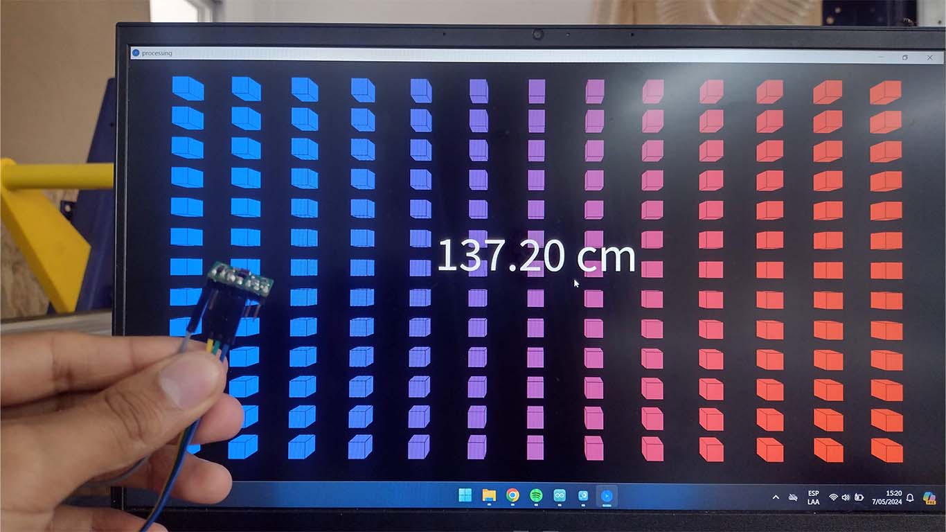
PROCESSING + TIME OF FLIGHT
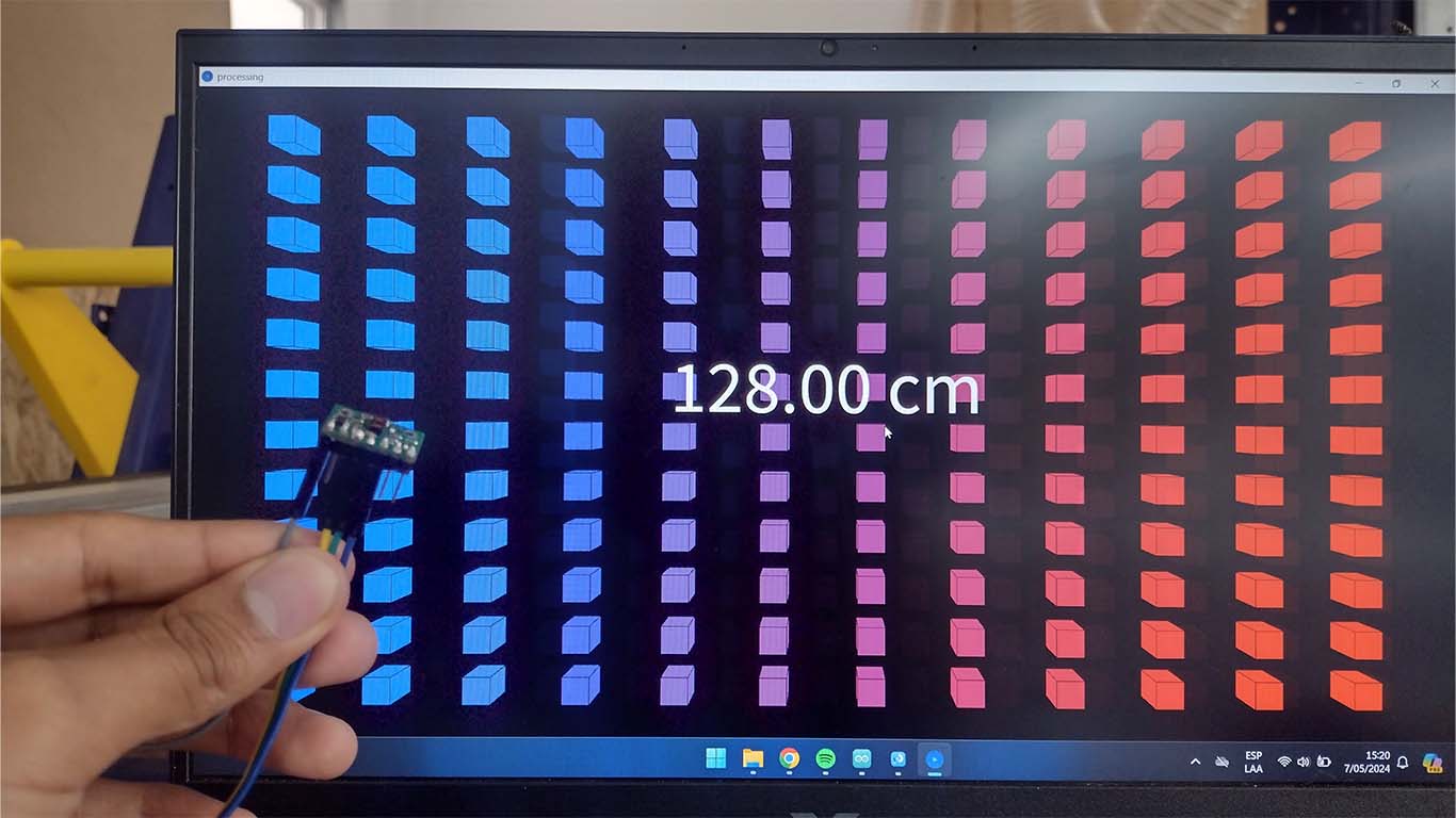
Now I designed an interface for the TIME OF FLIGHT sensor where I wanted to develop something more creative. For this reason, I wanted to make an interface that is made up of 3D cubes where it changes according to the distance measured by the sensor. At a few centimeters, there were fewer cubes and at greater distances, greater cube units. Here the programming process and result.
PROGRAMMING
For programming we have to download the POLOLU library of the VL53L1X sensor. I would recommend doing a test with the Arduino IDE serial to see if everything works very well and then synchronize with the PROCESSING. Here I leave both programming codes.
ARDUINO IDE PROGRAMMING
                            #include Wire.h
                                #include VL53L1X.h

                                VL53L1X sensor;

                                void setup() {
                                  Serial.begin(115200);
                                  Wire.begin();
                                  sensor.setTimeout(500);
                                  if (!sensor.init()) {
                                    Serial.println("Error detecting and initializing the sensor!");
                                    while (1);
                                  }
                                  sensor.setDistanceMode(VL53L1X::Long);
                                  sensor.setMeasurementTimingBudget(50000);
                                  sensor.startContinuous(50);
                                }

                                void loop() {
                                  uint16_t distance_mm = sensor.read();
                                  float distance_cm = distance_mm / 10.0;
                                  Serial.println(distance_cm);
                                  delay(100);
                                }
PROCESSING PROGRAMMING
                                import processing.serial.*;

                                Serial myPort;    // Object for serial communication
                                float distance;   // Variable to store the distance measured by the sensor
                                int numColumns;   // Number of cube columns
                                int numRows;      // Number of cube rows

                                void setup() {
                                size(1200, 900, P3D);  // Window size in 3D

                                // Specify the COM port your Arduino is connected to
                                String portName = "COM6";  // Make sure to change this to the correct port!

                                // Initialize serial port
                                myPort = new Serial(this, portName, 115200);  // Baud rate should match the setting in Arduino
                                myPort.bufferUntil('\n');  // Set up to read until a newline character is received
                                }

                                void draw() {
                                background(0);  // Black background

                                // Adjust the number of cube columns and rows based on the measured distance
                                if (!Float.isNaN(distance)) {
                                    // Limit minimum distance to 0.01 to avoid division by zero
                                    float limitedDistance = max(distance, 0.01);
                                    numColumns = int(map(limitedDistance, 0.01, 100, 1, 10));  // Map distance to number of cube columns
                                    numRows = int(map(limitedDistance, 0.01, 100, 1, 10));     // Map distance to number of cube rows

                                    float cubeSize = min(width / (numColumns * 2), height / (numRows * 2));  // Calculate cube size to fit all cubes in the window
                                    float spacingX = width / (numColumns + 1);  // Horizontal spacing between cubes
                                    float spacingY = height / (numRows + 1);    // Vertical spacing between cubes

                                    for (int i = 0; i < numColumns; i++) {
                                    for (int j = 0; j < numRows; j++) {
                                        float z = map(i * numRows + j, 0, numColumns * numRows - 1, 0.01, 1);  // Map height of each cube in the range 0.01-1
                                        float redValue = map(z, 0.01, 1, 0, 255);   // Calculate red component of color
                                        float blueValue = map(z, 0.01, 1, 255, 0);  // Calculate blue component of color
                                        fill(redValue, 0, blueValue);              // Gradient color from blue to red

                                        pushMatrix();
                                        translate((i + 1) * spacingX, (j + 1) * spacingY, 0);  // Position the cube on the plane
                                        box(cubeSize);  // Draw a cube of size cubeSize
                                        popMatrix();
                                    }
                                    }
                                }

                                // Display measured distance (in 3D)
                                fill(255);
                                textSize(100);
                                textAlign(CENTER, CENTER);
                                text(nf(distance, 0, 2) + " cm", width / 2, height / 2 - 50, 100); // Text offset upwards
                                }

                                void serialEvent(Serial myPort) {
                                // Read data from the serial port when available
                                String inData = myPort.readStringUntil('\n');
                                if (inData != null) {
                                    distance = float(trim(inData));  // Convert received data to float
                                }
                                }
RESULT
The result seems very nice and interesting to me, I was able to show the initial idea of the cubes and also show the distance measured by the sensor. Here is a video of the result.
PROCESSING + OUTPUTS
For the OUTPUTS I wanted to make interfaces that can apply an action to each of the outputs. For this assignment I used the SERVOMOTOR and the NEOPIXEL so that from the design I made in PROCESSING I could perform an action. First I will show you what was achieved with the servomotor and then the neopixel.
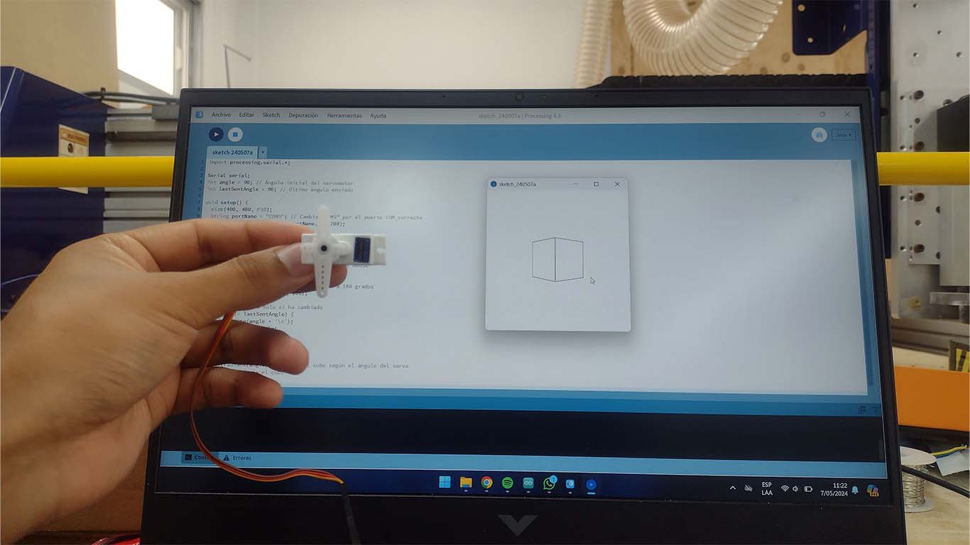
PROCESSING + SERVOMOTOR
For the design of the SERVOMOTOR interface, I reviewed many documentations with this output and I wanted to do something different. I took advantage of the design I had made with the 3D cubes to propose a design of a cube that, according to the movement made with the mouse, rotated left and right. This movement will replicate and can be displayed on the servomotor. Here the process and the result.
PROGRAMMING
For programming the servomotor, take my reference from what was done in the OUTPUT DEVICES assignment. From there I began to work on the processing and began to design the interface with a cube that provided information to the servomotor and the direction in which it rotated. Here are the programming codes.
ARDUINO IDE PROGRAMMING
                            #include Servo.h

                                #define SERVO_PIN 3

                                Servo myServo;

                                void setup() {
                                  Serial.begin(115200);
                                  myServo.attach(SERVO_PIN);
                                }

                                void loop() {
                                  if (Serial.available() > 0) {
                                    int angle = Serial.parseInt(); // Read servo angle from serial port

                                    // Limit the angle within the valid range
                                    angle = constrain(angle, 0, 180);

                                    // Move the servo to the received angle
                                    myServo.write(angle);
                                  }
                                }
PROCESSING PROGRAMMING
                                import processing.serial.*;

                                Serial serial;
                                int angle = 90; // Initial angle of the servo motor
                                int lastSentAngle = 90; // Last sent angle

                                void setup() {
                                size(400, 400, P3D);
                                String portName = "COM5"; // Change "COM5" to the correct COM port
                                serial = new Serial(this, portName, 115200);
                                }

                                void draw() {
                                background(255);

                                // Calculate angle based on mouse position
                                angle = int(map(mouseX, 0, width, 0, 180));

                                // Limit angle within the range of 0 to 180 degrees
                                angle = constrain(angle, 0, 180);

                                // Send angle only if it has changed
                                if (angle != lastSentAngle) {
                                    serial.write(angle + '\n');
                                    lastSentAngle = angle;
                                }

                                // Draw the 3D cube
                                translate(width/2, height/2, 0);
                                rotateY(radians(angle)); // Rotate the cube based on servo angle
                                box(100); // Draw the cube
                                }
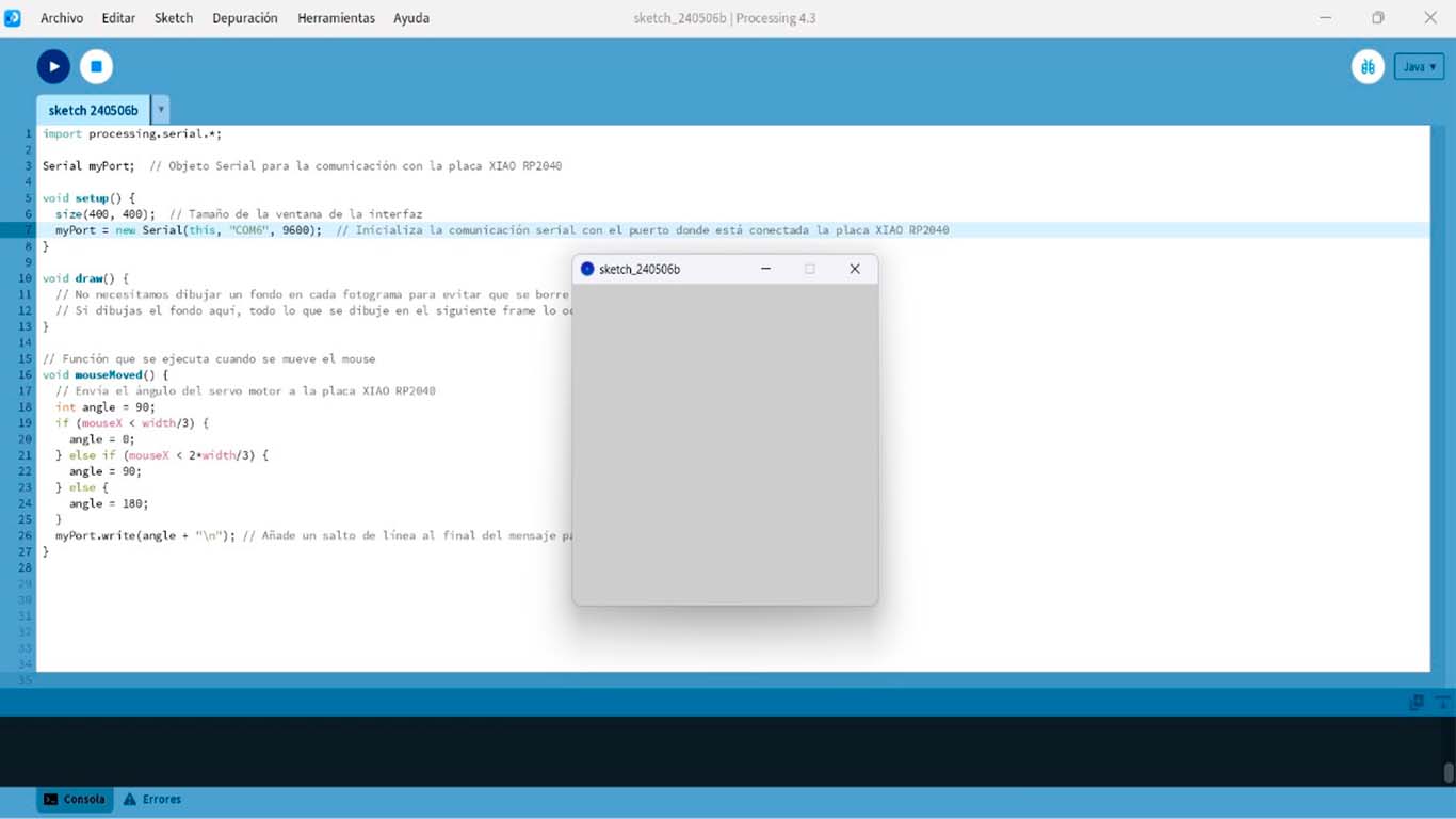
RESULT
In the video of the result we can see how the servomotor moves according to the direction in which we rotate the Processing interface cube. The development of this interface was very interesting and I didn't think it would be possible to manage an output from processing.
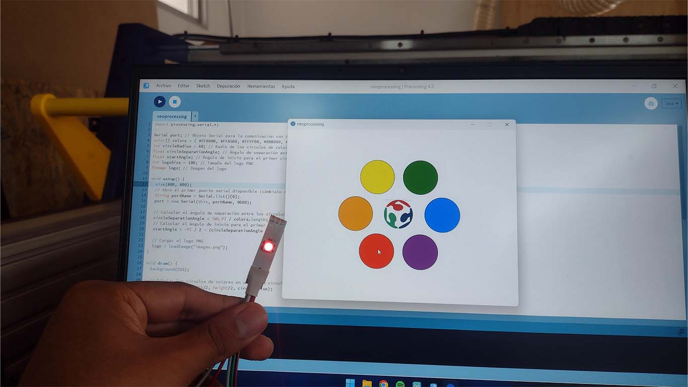
PROCESSING + NEOPIXEL
Finally, for the neopixel I wanted to develop an interface that allows me to change the color of the LED when clicking on each option I had. Additionally, I added the FAB ACADEMY logo to the center to see if it was possible to see images. Here is a screenshot of what was achieved and the process.
PROGRAMMING
In programming I had certain problems with the PROCESSING since sometimes it did not send the correct color to the one I clicked on. There was a problem with the click size that we must configure in its programming so that it can detect exactly the color we want. Here are the 2 programming codes.
ARDUINO IDE PROGRAMMING
                            #include Adafruit_NeoPixel.h

                                #define NEOPIXEL_PIN 3 // Pin to which the Neopixel is connected
                                #define NUM_PIXELS 1 // Number of Neopixels in the strip

                                Adafruit_NeoPixel strip(NUM_PIXELS, NEOPIXEL_PIN, NEO_GRB + NEO_KHZ800);

                                void setup() {
                                  strip.begin(); // Initialize the Neopixel
                                  strip.show(); // Initialize all pixels as 'off'
                                  strip.setBrightness(50); // Set brightness (0 to 255)
                                  Serial.begin(9600); // Initialize serial communication
                                }

                                void loop() {
                                  // Wait to receive data over the serial port
                                  if (Serial.available() > 0) {
                                    // Read received data until a newline character is encountered
                                    String data = Serial.readStringUntil('\n');
                                    // Print received data
                                    Serial.println("Received data: " + data);
                                    // Separate red, green, and blue values
                                    int commaIndex1 = data.indexOf(',');
                                    int commaIndex2 = data.indexOf(',', commaIndex1 + 1);
                                    int r = data.substring(0, commaIndex1).toInt();
                                    int g = data.substring(commaIndex1 + 1, commaIndex2).toInt();
                                    int b = data.substring(commaIndex2 + 1).toInt();
                                    // Set Neopixel color
                                    strip.setPixelColor(0, strip.Color(r, g, b));
                                    strip.show();
                                  }
                                }
PROCESSING PROGRAMMING
                                import processing.serial.*;

                                Serial port; // Serial object for communication with Arduino
                                color[] colors = { #FF0000, #FFA500, #FFFF00, #008000, #0000FF, #800080 }; // Rainbow colors: red, orange, yellow, green, blue, purple
                                int circleRadius = 60; // Radius of the color circles
                                float circleSeparationAngle; // Angle of separation between circles
                                float startAngle; // Starting angle for the first circle
                                int logoSize = 100; // Size of the PNG logo
                                PImage logo; // Logo image

                                void setup() {
                                size(800, 600);
                                // Open the first available serial port (change it if necessary)
                                String portName = Serial.list()[0];
                                port = new Serial(this, portName, 9600);

                                // Calculate the angle of separation between circles
                                circleSeparationAngle = TWO_PI / colors.length;
                                // Calculate the starting angle for the first circle
                                startAngle = -PI / 2 - (circleSeparationAngle * (colors.length - 1)) / 2;

                                // Load the PNG logo
                                logo = loadImage("images.png");
                                }

                                void draw() {
                                background(255);

                                // Draw the color circles in a circular pattern
                                drawColorCircles(width/2, height/2, circleRadius);

                                // Draw the logo in the center
                                imageMode(CENTER);
                                image(logo, width/2, height/2, logoSize, logoSize);
                                }

                                void mouseClicked() {
                                // Check if one of the color circles was clicked
                                for (int i = 0; i < colors.length; i++) {
                                    float angle = startAngle + circleSeparationAngle * i;
                                    float x = width/2 + cos(angle) * 150; // Outer circle radius
                                    float y = height/2 + sin(angle) * 150; // Outer circle radius
                                    if (dist(mouseX, mouseY, x, y) < circleRadius) {
                                    sendColor(colors[i]);
                                    break;
                                    }
                                }
                                }

                                void sendColor(color c) {
                                // Send color to Arduino via serial port
                                port.write(red(c) + "," + green(c) + "," + blue(c) + "\n");
                                }

                                void drawColorCircles(float centerX, float centerY, int radius) {
                                for (int i = 0; i < colors.length; i++) {
                                    float angle = startAngle + circleSeparationAngle * i;
                                    float x = centerX + cos(angle) * 150; // Outer circle radius
                                    float y = centerY + sin(angle) * 150; // Outer circle radius
                                    fill(colors[i]);
                                    ellipse(x, y, radius * 2, radius * 2);
                                }
                                }
RESULT
As a result we can see that all the colors shown in the neopixel are correct according to those found in the Processing interface. Here is the video demonstrating what was achieved.
CONCLUSIONS
I consider it to be a very fun and stressful week at the same time, because there are many tools to learn about and work with. In my case, I worked with PYTHON + TKINTER and it seems like a very simple but basic program, you can't make many innovative designs, maybe if we want something basic and simple, we can use the program. On the other hand, PROCESSING is a program that allows you to achieve many very interesting interface designs and the truth is that I really like it because it is easy to link with the ARDUINO IDE that I use for programming. In time I would have liked to learn more tools but I recommend both.
REVIEW OF THE CLASS
During the review of this class I volunteered in the minute 1:28:30
Clic here to 20240508 review from Academany on Vimeo.
FILES
Here you can download all the files that I have made for the following assignment: