This week's assignment was:
ASSIGNMENT
- Develop a plan for dissemination of your final project.
- Prepare drafts of your summary slide (presentation.png, 1920x1080) and video clip (presentation.mp4, 1080p HTML5, < ~minute, < ~10 MB) and put them in your root directory.
ORGANIZATION
Here I show how I organized myself for this week.
| Wednesday 29th: | Fab Academy classes, organization of the week and I begin to carry out my dissemination plan and review some references from colleagues about how they worked on the invention of their project. |
|---|---|
| Thursday 30Th: | I start making my dissemination plan and I also start designing my slide. |
| Friday 31th: | Development of the first 3 questions of the assignment and development of my final project. |
| Saturday 01th: | Advance in my video of the final project |
| Sunday: 02th: | Preview of my final project, layout of the slide and my final project video. |
| Monday 03th: | Review and correction of documentation. Update and changes for last commit. |
| Tuesday 04th: | Documentation and last commit of the week. |
ASSIGNMENT
INVENTION
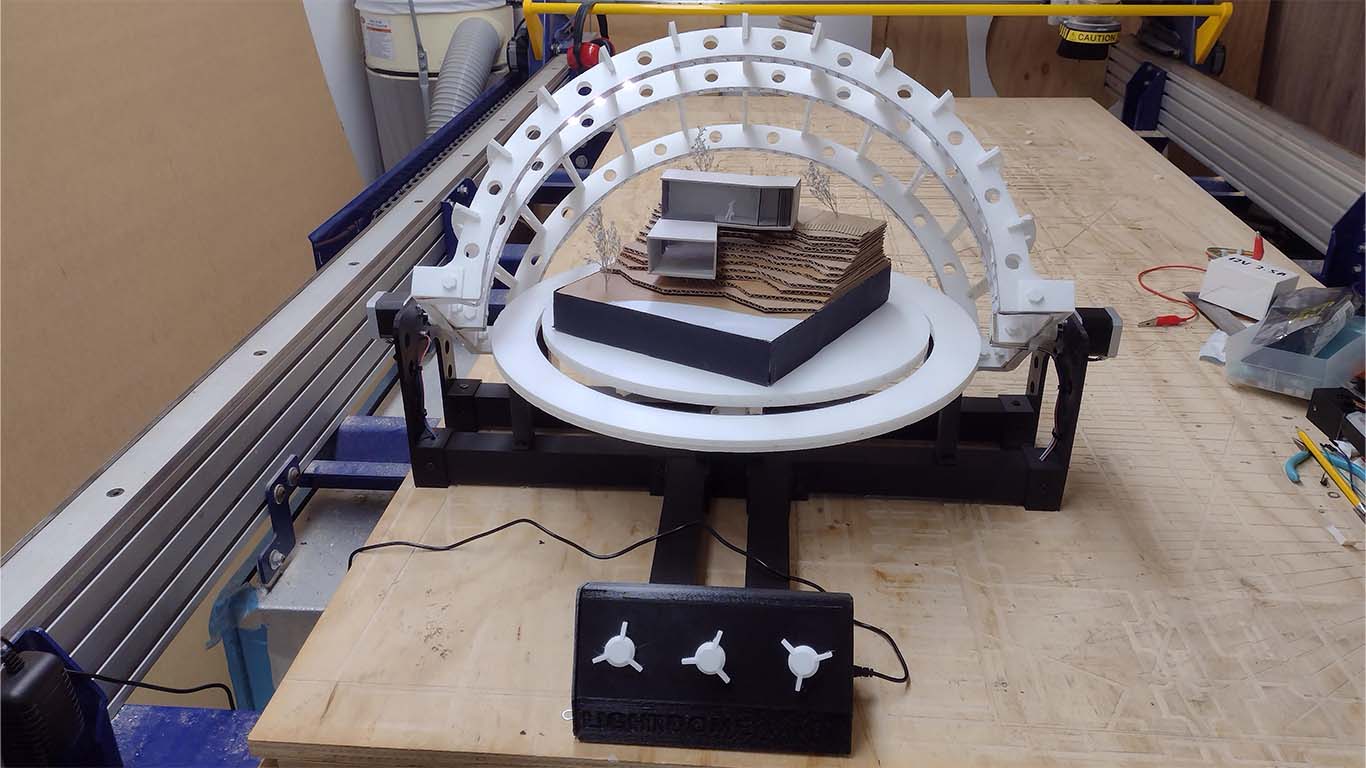
LIGHTDOME is the name of my project, it is an artifact inspired by the heliodon. The Heliodon is an instrument that is used to simulate the path of the sun in architectural models and is very useful for architecture students and professionals in the design process and analysis of the sun's incidence in architectural projects to achieve adequate orientation. LIGHTDOME is mainly composed of the word LIGHT which means light, and DOME for dome, both make up the word that is inspired by the characteristics and shape of heliodons.
For the FAB ACADEMY 2024, my idea was to make a heliodon that would serve as an artifact for the students and professors of the architecture program at the Scientific University of the South with the aim of improving the teaching methodology about the trajectory and solar incidence in architecture as part of bioclimatics. Therefore, thanks to the FAB ACADEMY week after week I was able to experiment and learn many processes that allowed me to innovate the way I wanted to approach the project.
LIGHTDOME presents different processes, where the structural part was made with light materials so that any student or professional can develop it quickly and using laser cutting, where each part was designed and manufactured by myself. The electronic part, the idea is to use basic components that we can get in any electronic store as well as the 3D printed joints and bases, which were manufactured by me. All of this can be used and downloaded without restrictions, but they are exclusive objects and I would do their sale or distribution myself.
INTELLECTUAL PROPERTY
Regarding intellectual property, both the students who are part of the FAB ACADEMY and myself, our work carried out is supported by the MIT LICENSE, which is characterized by being OPEN SOURCE, that is, that anyone who enters my site website can see, copy, test, modify, improve and merge without restrictions my documentation prepared for the FAB ACADEMY.
Everything done in the FAB ACADEMY is for public use, in my case I used the CREATIVE COMMONS license, which in the following LINK we can easily answer a questionnaire that allows us to obtain the result of the license to which our project best adapts
In my case, I plan to use the following license:
This work is licensed under a Creative Commons Attribution-NonCommercial-ShareAlike 4.0 International
These are the characteristics of why I choose this type of license:
BUSINNESS MODELS
The way in which I would like to disseminate my project and the knowledge obtained at the FAB ACADEMY would be through an article or be part of the magazine of the Cientifica del Sur University, showing the digital manufacturing techniques with their respective processes that were carried out. to achieve my project.
Additionally, I could create an instruction manual where users can build LIGHTDOME following the steps, cutting and 3D printing the parts that compose it and following the steps in my documentation. However, with the electrical board, you could send manufacturing to any PCB production house so that we can build the electrical boards along with their components so that the device can work without any inconvenience and manufacturing would be faster.
Finally, I would like to share my project with other people from the FAB LAB NETWORK who can work on artifacts for education and specifically for teaching in architecture or technologies that can be applied in it. I feel that it is the beginning of something very big and this project is part of this beautiful beginning that I feel proud to have achieved.
SLIDE AND VIDEO CLIP OF MY FINAL PROJECT
To design my slide for the presentation of my final project I used the PHOTOSHOP program, where I began to place some photographs that I had of my progress of my final project for this final sketch. I started to diagram and show all the components that are necessary for the slide.
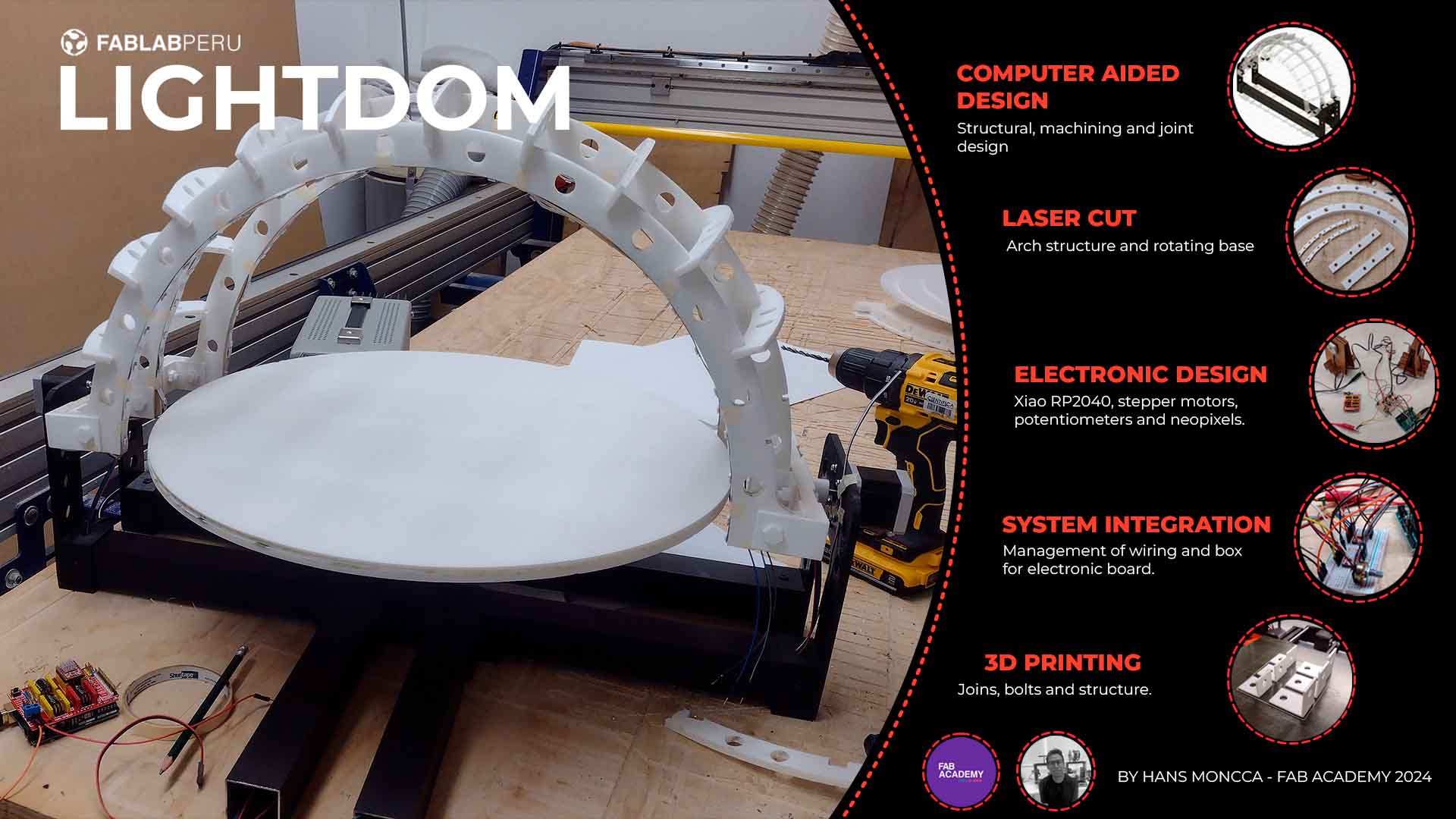
On the other hand, I also began to develop my video for my final project in the DAVINCI RESOLVE program, where I began to separate the seconds that were necessary to explain the reason, the process and the result. Here I attach a video of my first progress until this week, for the final delivery I hope to have everything ready for my presentation.
FINAL PROJECT
THIRD SPIRAL
For week 18 and the last week I had to develop my final project, it was the hardest because I had many problems with programming and 3D printing, but little by little I was able to solve each problem that came along the way. For this spiral the idea was to close each process carried out that included my project. Here is the process developed in the last week of the FAB ACADEMY of my final project.
LASER CUTTING
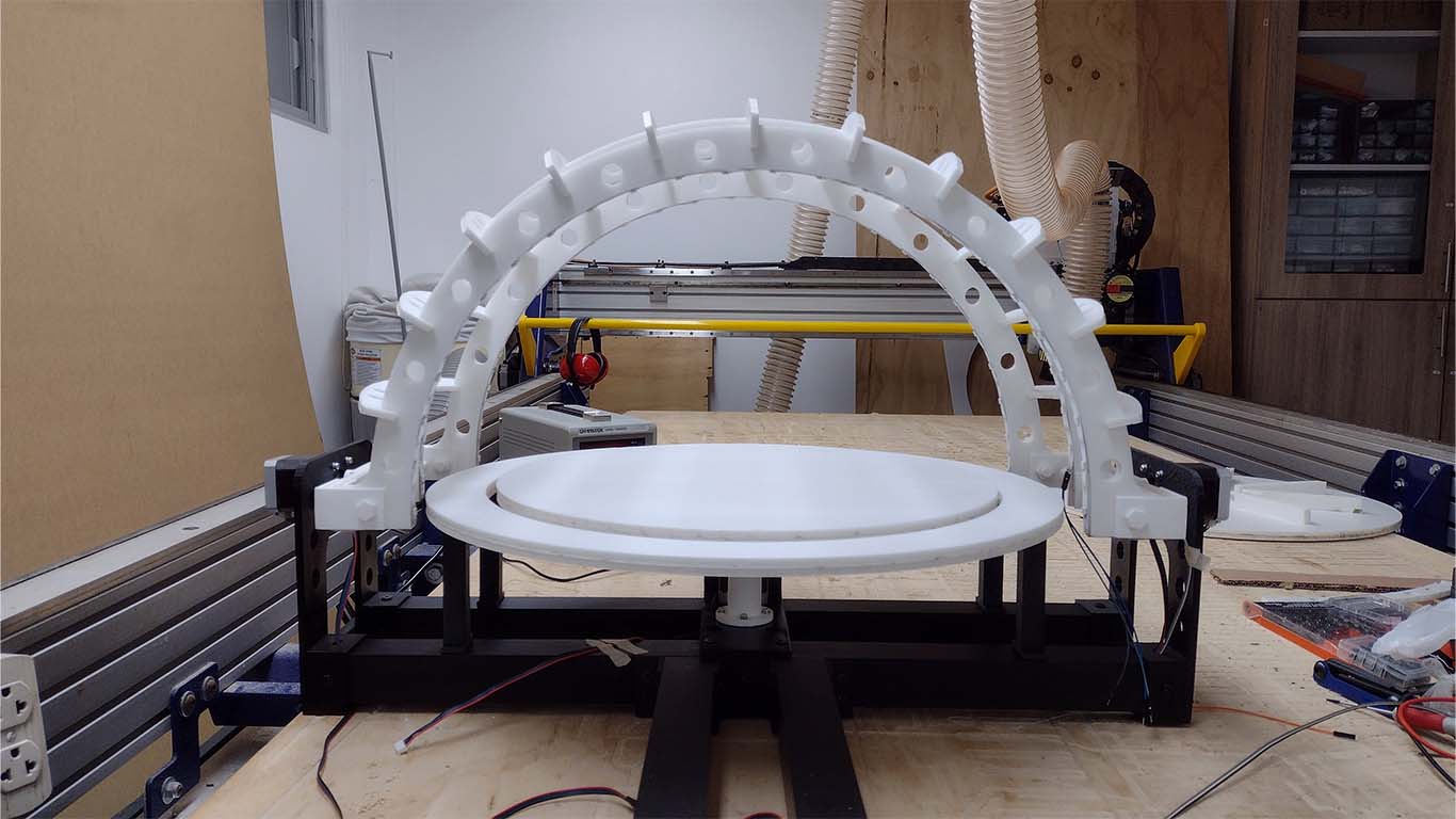
For this week I had ready the design and cutting of the foam for my arch structure, which was all laser cut. Thanks to the progress of the previous spirals I was able to carry out and complete the process. Here is a photograph of the completed process.
3D PRINTING
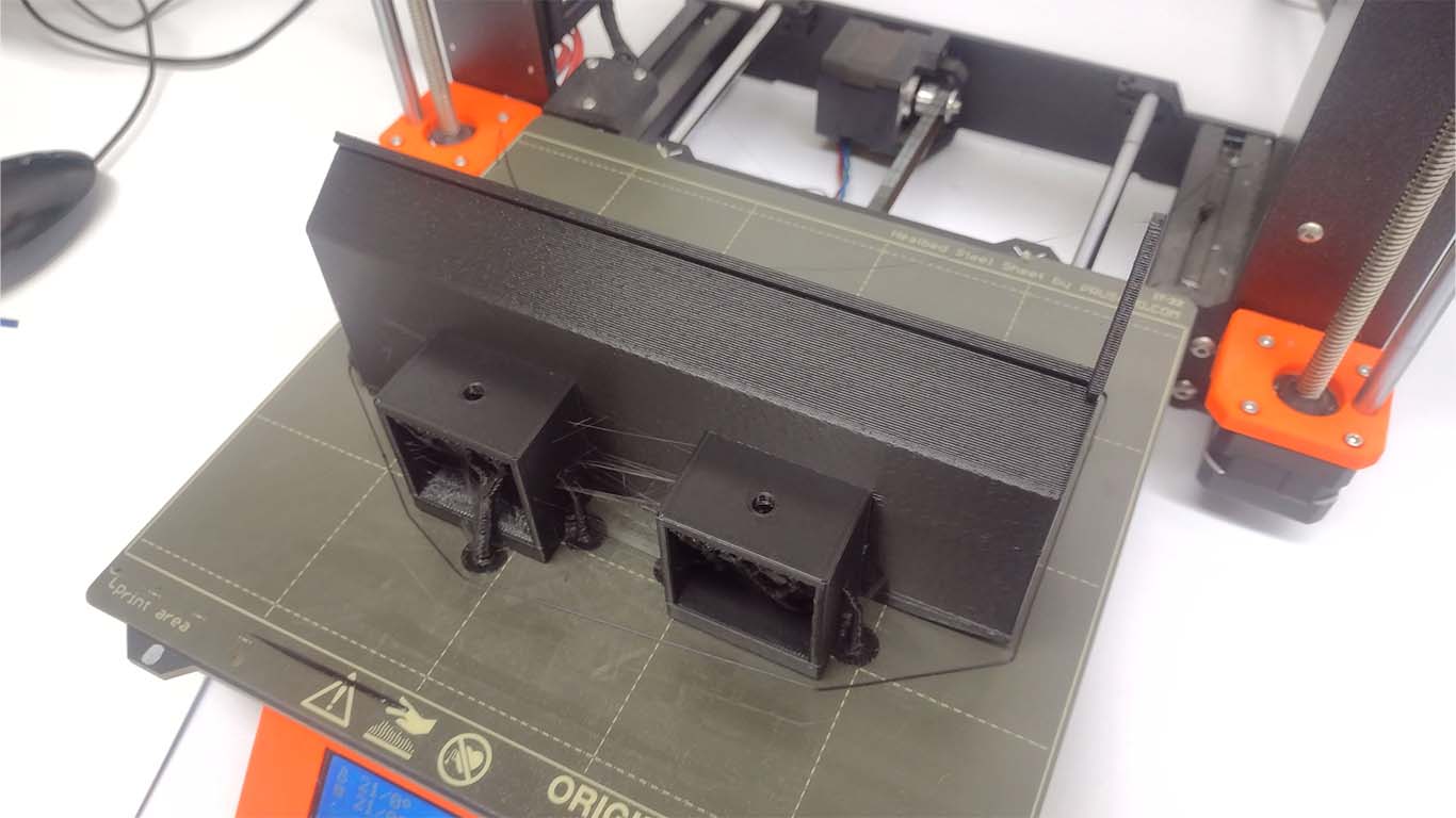
For what comprises 3D printing, I made all the pieces that include the arches, I made the side supports and I only needed to make the control box where the project's electronic board and the command control would be located so that the user could use the artifact. Here is a screenshot of the last pieces to print for this week.
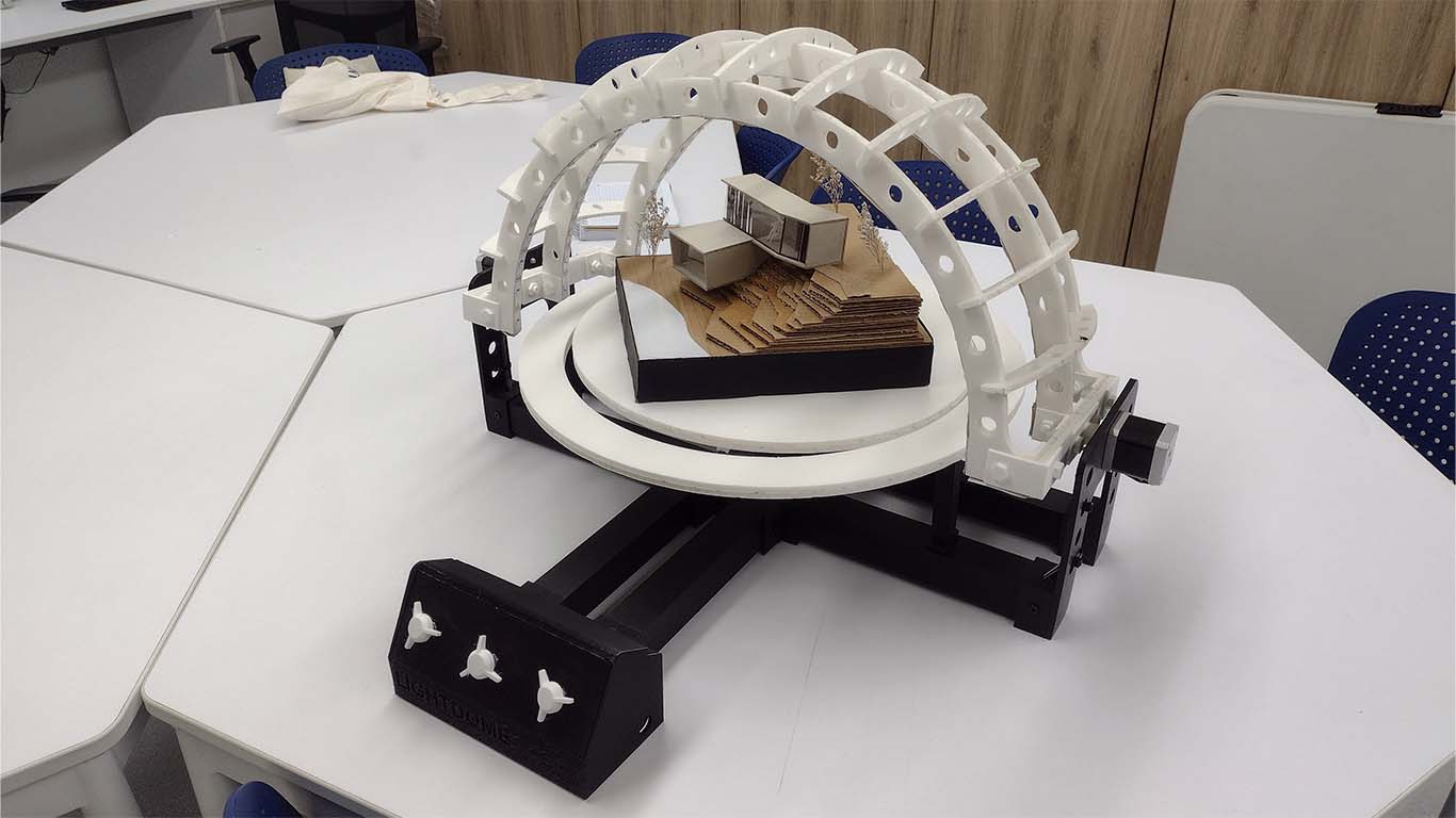
Finally, after everything was ready, assembly began to be completed and everything ready for final delivery. Here is a screenshot of the project along with the missing control box and was carried out this week.
ELECTRONIC DESIGN
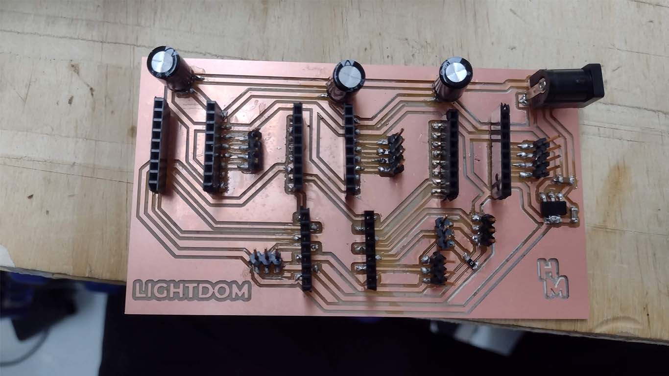
On the other hand, I started to design my own board for my final project where it is more specified on my PROJECT DEVELOPMENT page, where the design was made in KICAD, all the electrical components were milled and soldered. This was the last stage of my electronic design that I was missing.q
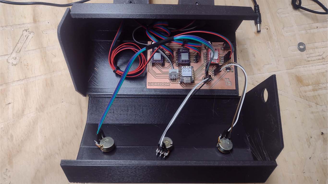
Here is a photograph of all the soldered components and the drivers for the stepper motors in place. Obviously during the week the programming was worked on to be able to program the final board.
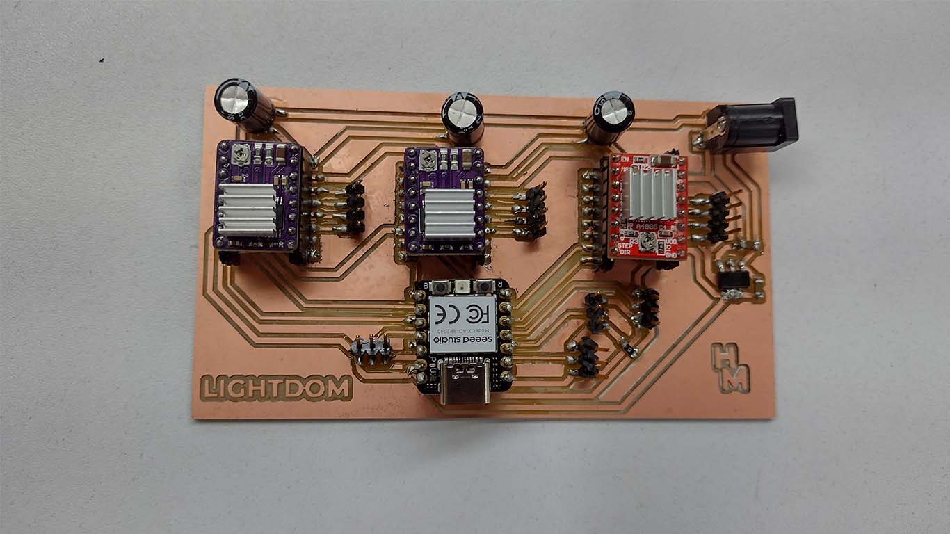
Finally, then I proceeded to connect all the input and output devices that included my project and it was located in its integrated systems box where everything was designed for its correct location and operation. Everything was achieved this week happily.
RESULT
To conclude the third spiral I can say that everything done works, where each process was very difficult to achieve and that spiral after spiral could come true. These last weeks were difficult since time was a pressure to move forward and there were moments where I felt that nothing was progressing, but it is part of the process and the idea was achieved. I am very happy to have achieved the goal of completing my project for the final delivery. You can see my presentation on the PRESENTATION page.
