This week's assignment was:
- Characterize your lasercutter's focus, power, speed, rate, kerf, joint clearance and types.
- Document your work to the group work page and reflect on your individual page what you learned.
- Design, lasercut, and document a parametric construction kit, accounting for the lasercutter kerf, which can be assembled in multiple ways.
- Cut something on the vinyl cutter.
ORGANIZATION
Here I show how I organized myself for this week.
| Wednesday 7th: | Fab Academy classes |
|---|---|
| Thursday 8th: | Group order progress and software research for both machines. |
| Friday 9th: | Laser cutting of combs for group order and documentation 1 of the advanced. |
| Saturday 10th: | Parametric figure cutting for individual order and assembly of figures. |
| Sunday: 11th: | Documentation and commit of the advanced. |
| Monday 12th: | Design and cutting of vinyl for individual orders. |
| Tuesday 13th: | Review of all documentation and last commit of the week. |
GROUP ASSIGNMENT
Here I leave the link to go to the group assignments page.
Clic here to visit the WEEK 3 GROUP ASSIGNMENT PAGE
LASER CUTTING
LASER CUTTER
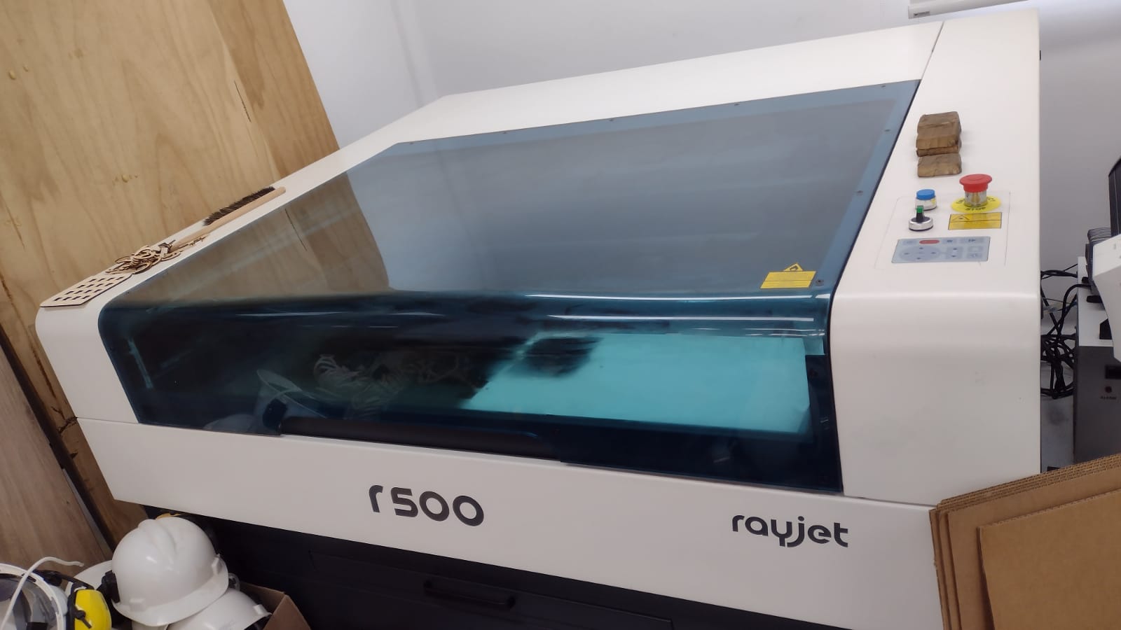
The laser cutter that we have at the Universidad Cientifica del Sur is the RAYJET R500. Which has the following technical specifications:
| WORK SURFACE | 1300 x 900 mm |
|---|---|
| LASER POWER | SEALED LASER CO2 DC 60 / 100 / 120 W |
| LASER SYSTEM POWER CONSUMPTION | 100 - 250V, 1100 - 1500 W |
| MAX PROCESSING SPEED | 1 m/s |
The laser cutter is used to cut materials such as cardboard, wood, acrylic and foam. Materials that are used by students who are studying architecture at the university. I learned to use the machine last year from my friend Maryori who taught me how to use it, but we always had doubts about the cutting configuration of the machine with the different materials, so we will take advantage of this assignment to have our value test for the different materials we use.
The materials that I will use to develop the task that is related to the laser cutter will be 3mm PLYWOOD, which is a sheet of wood and CARDBOARD of 4 mm.
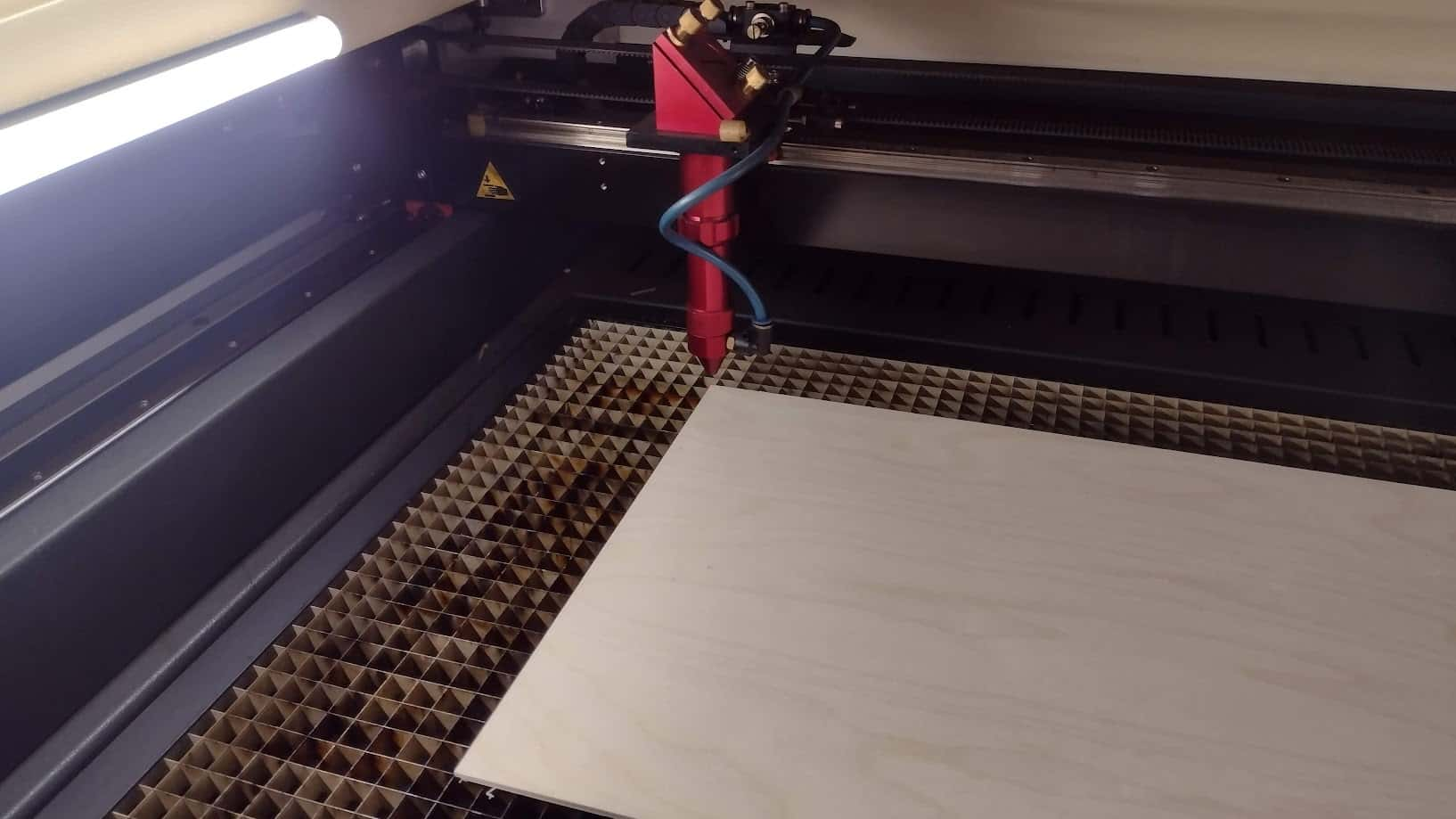
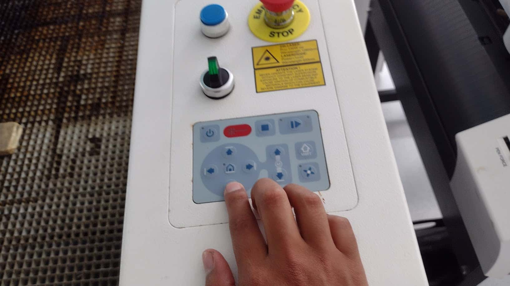
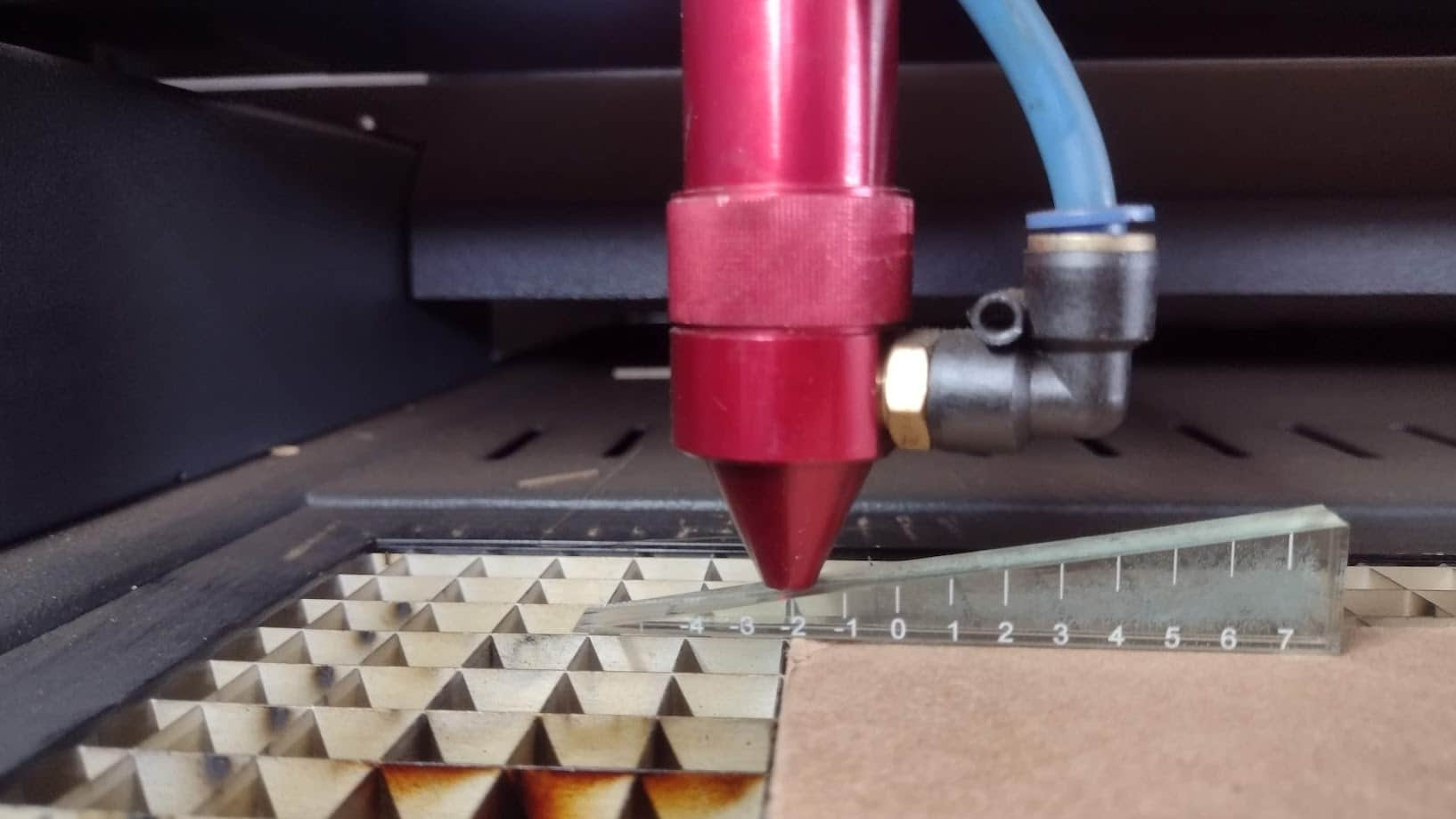
STEP 1: POWER ON AND HORIZONTAL AND VERTICAL CALIBRATION
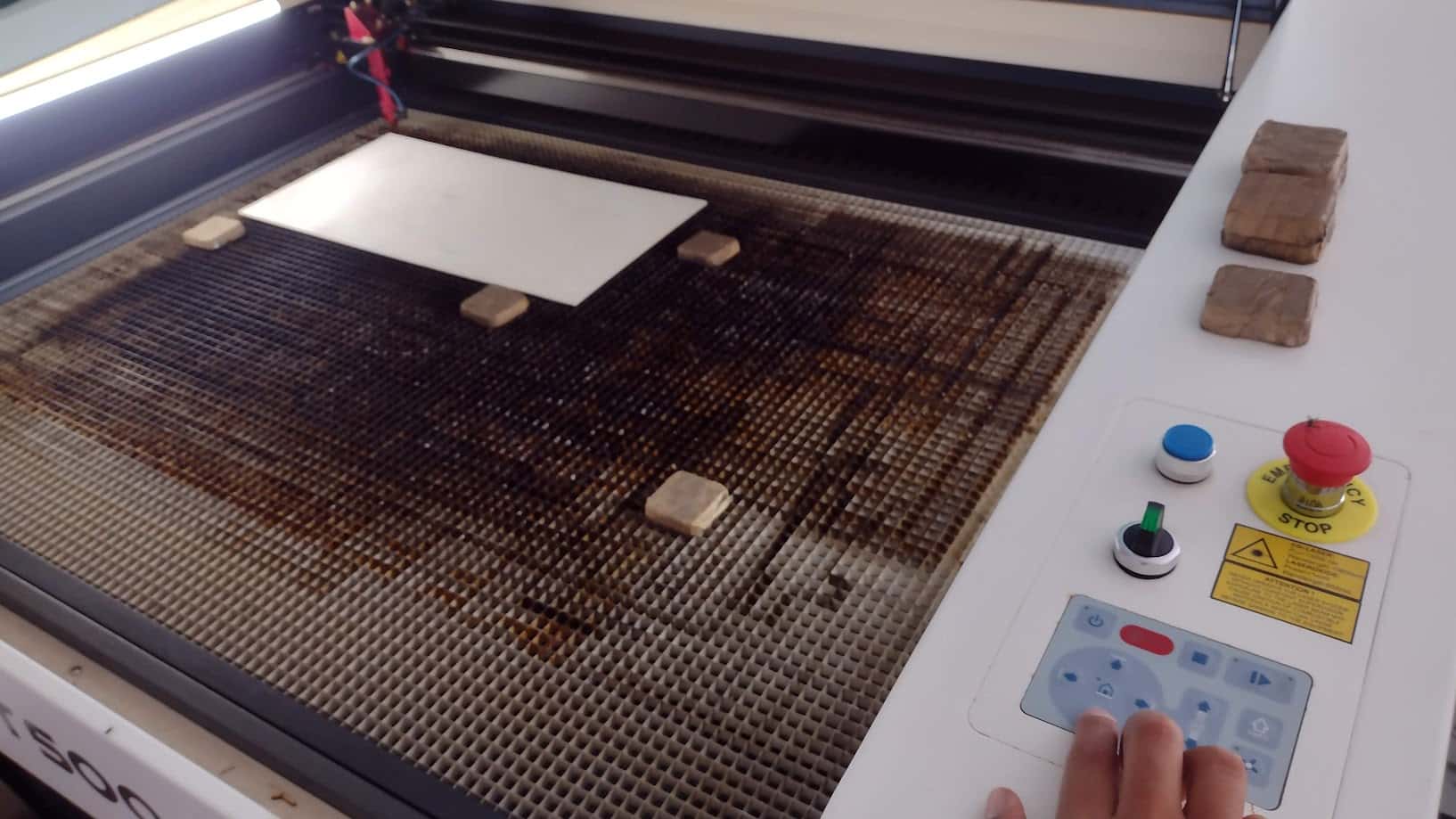
To start using the machine it is necessary to calibrate the location of the laser because the laser point is located where the previous work was done.
Therefore, for the machine to be calibrated in location again, we have to close the safety cover and it returns to the point x=0 and Y=0 that it has programmed.
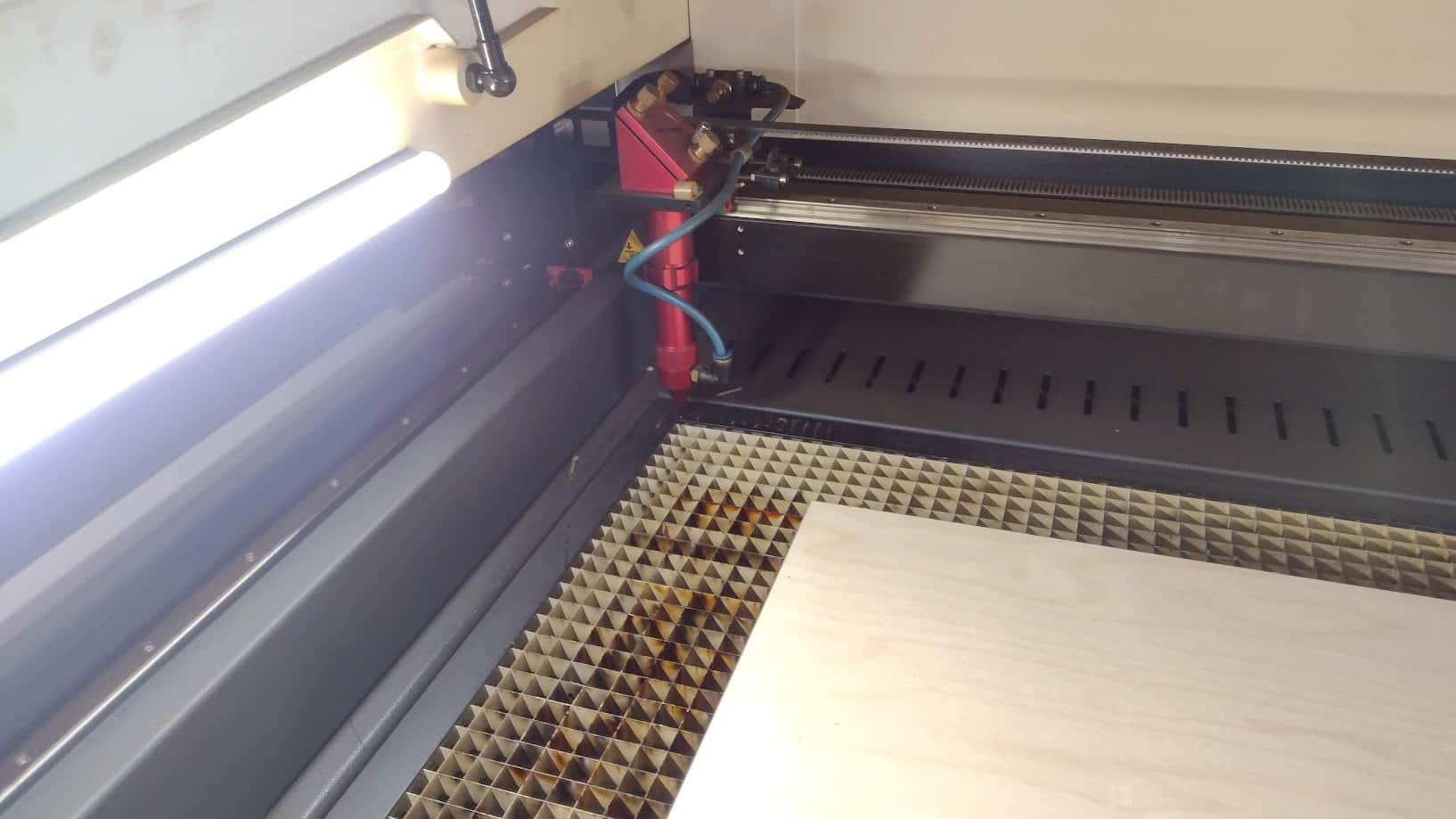
From that moment on, the user can move it manually with the buttons to the point where they consider it convenient to start working with the materials.
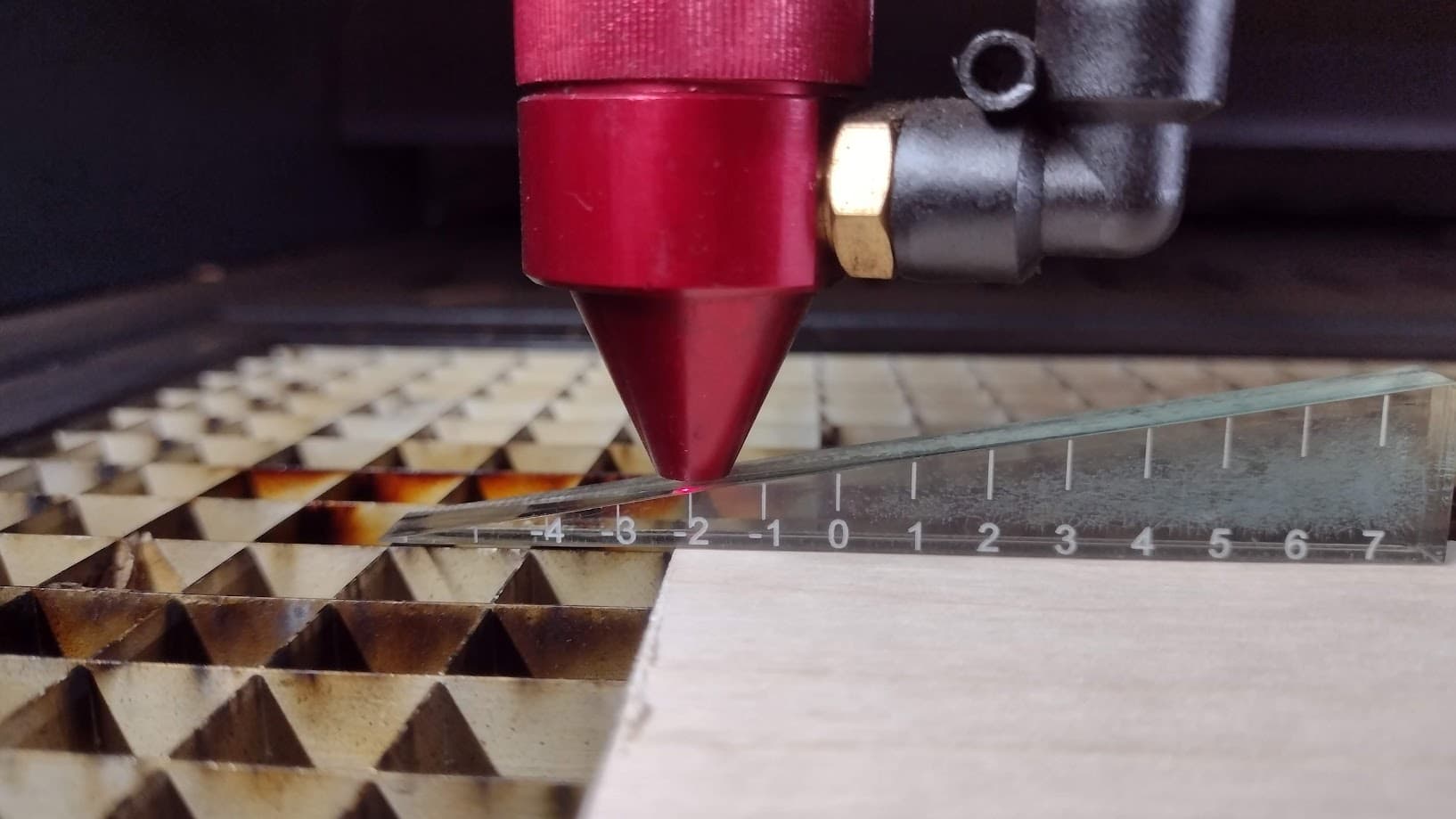
Finally, we have to calibrate the height of the laser, so using a triangular tool we can analyze the distance that the laser cut will have with the material. In this case we will use 2 distance units for correct work on both materials as recommended by the supplier.
STEP 2: CUTTING AND ENGRAVING TEST
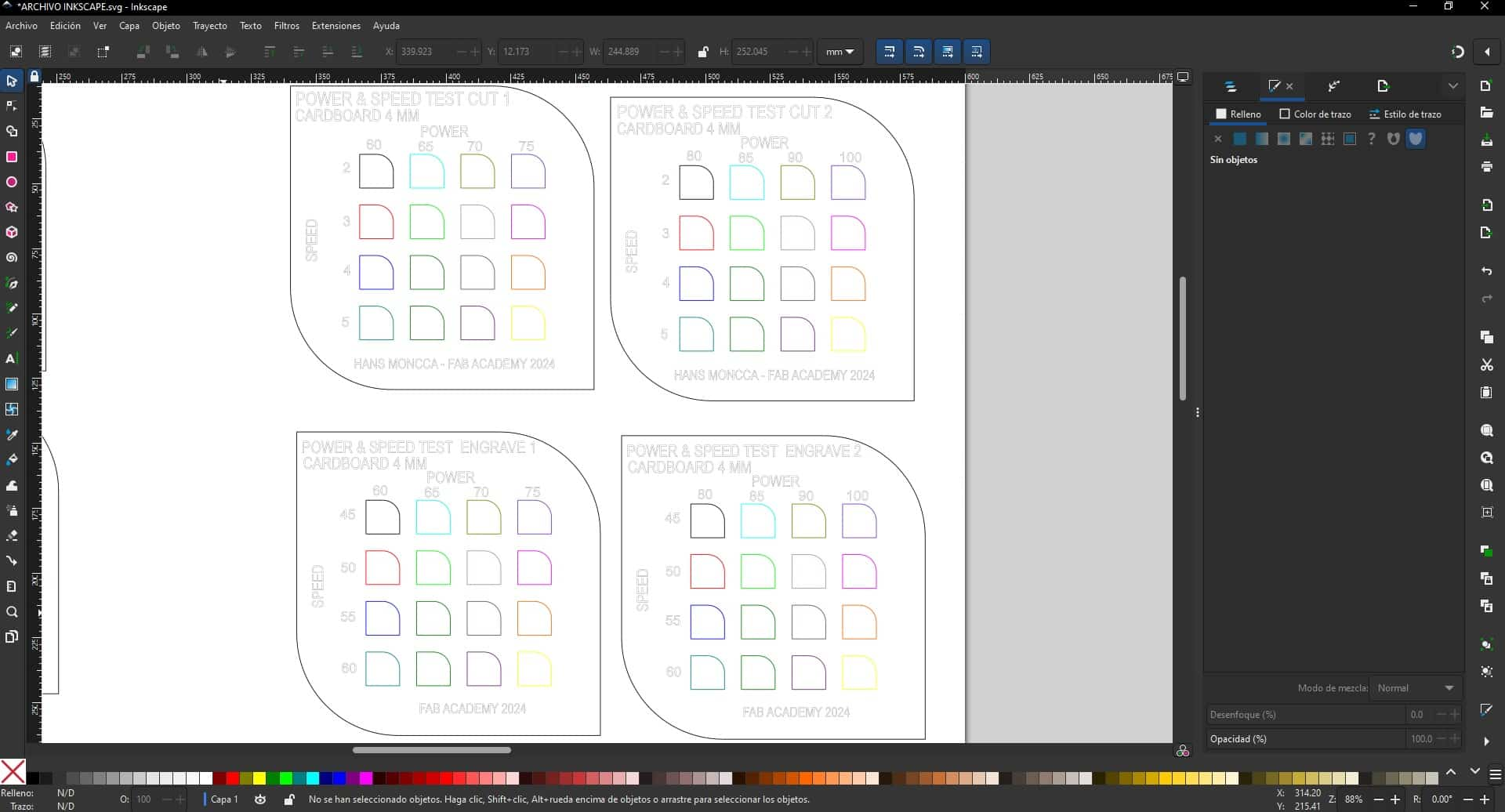
To draw the table of values that is made up of the power and speed of the laser, I started working on it in AUTOCAD a software that I use and it became easier for me to design the table.
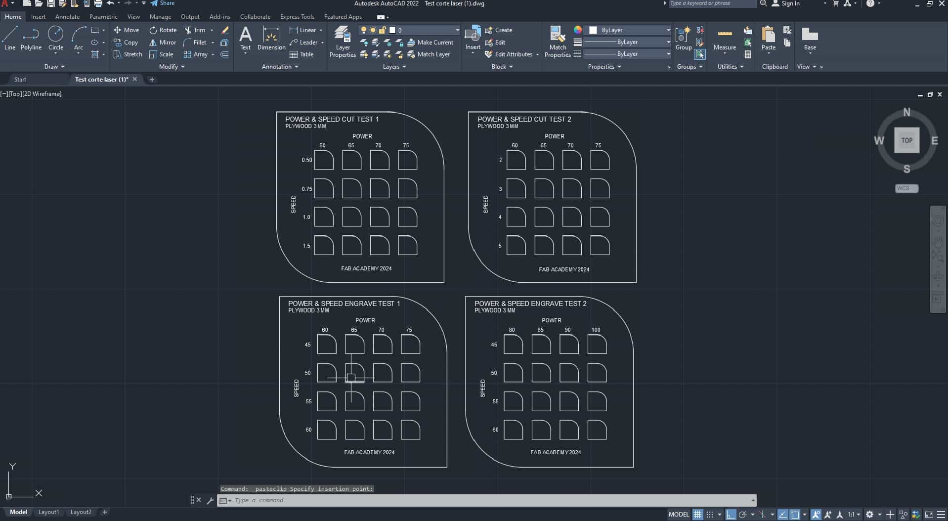
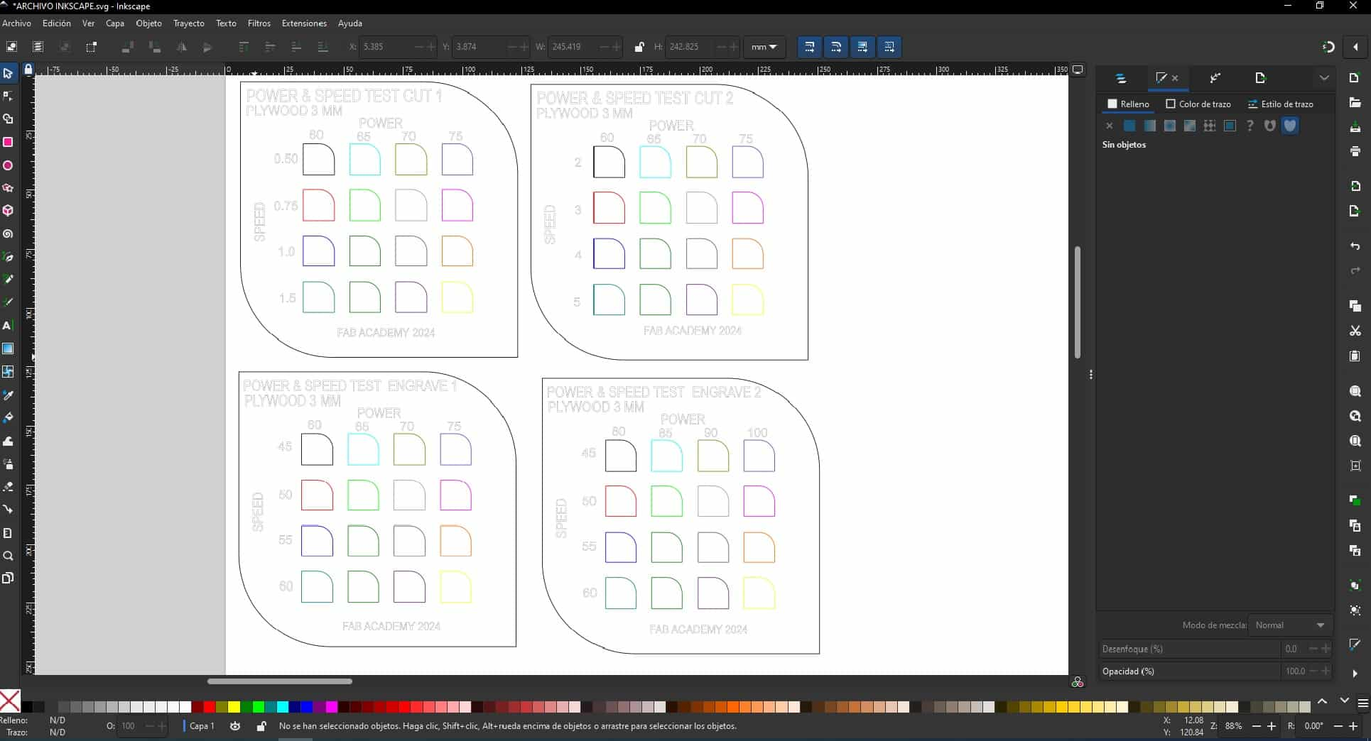
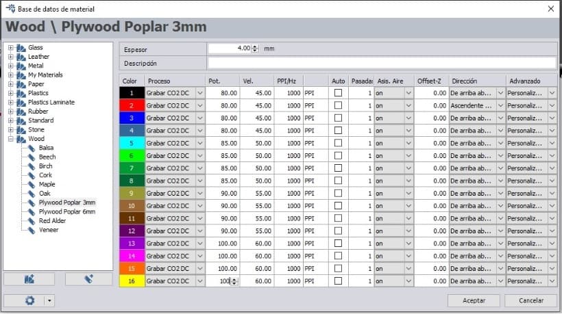
After, we export to INKSCAPE to be able to place the respective colors on each frame that is composed according to the power and speed. Different colors will be used so that the laser cutter software can read and we can configure the power and speed according to the settings we have in the software.
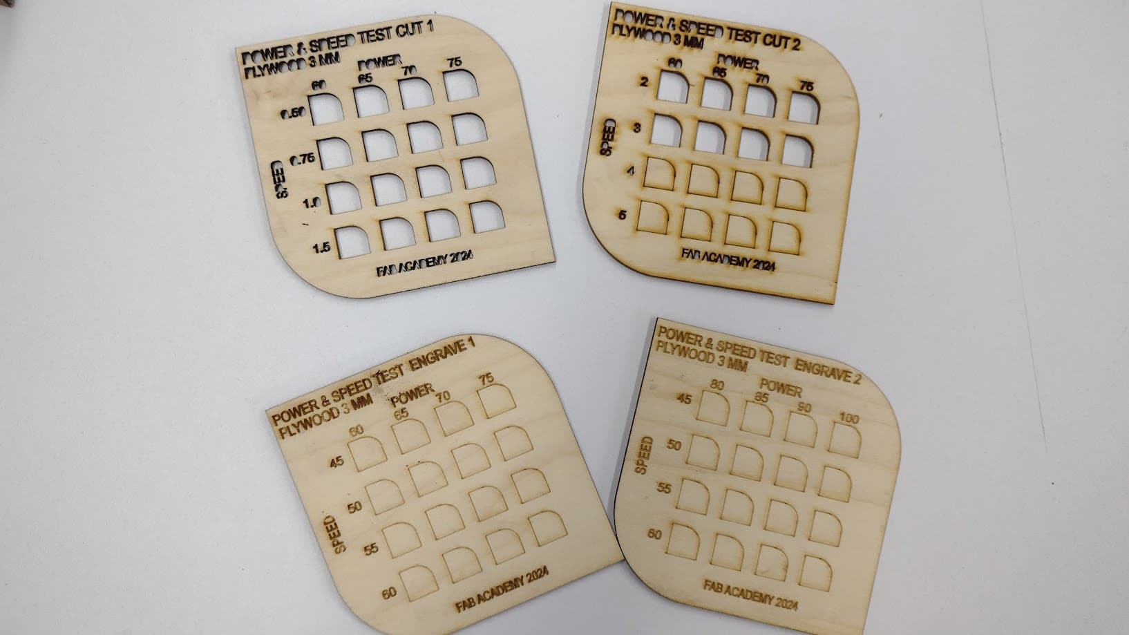
First we started working with PLYWOOD where we configured heir respective values for each board to see the difference between them in cutting and engraving.
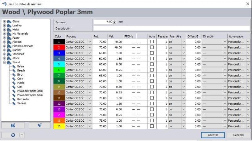
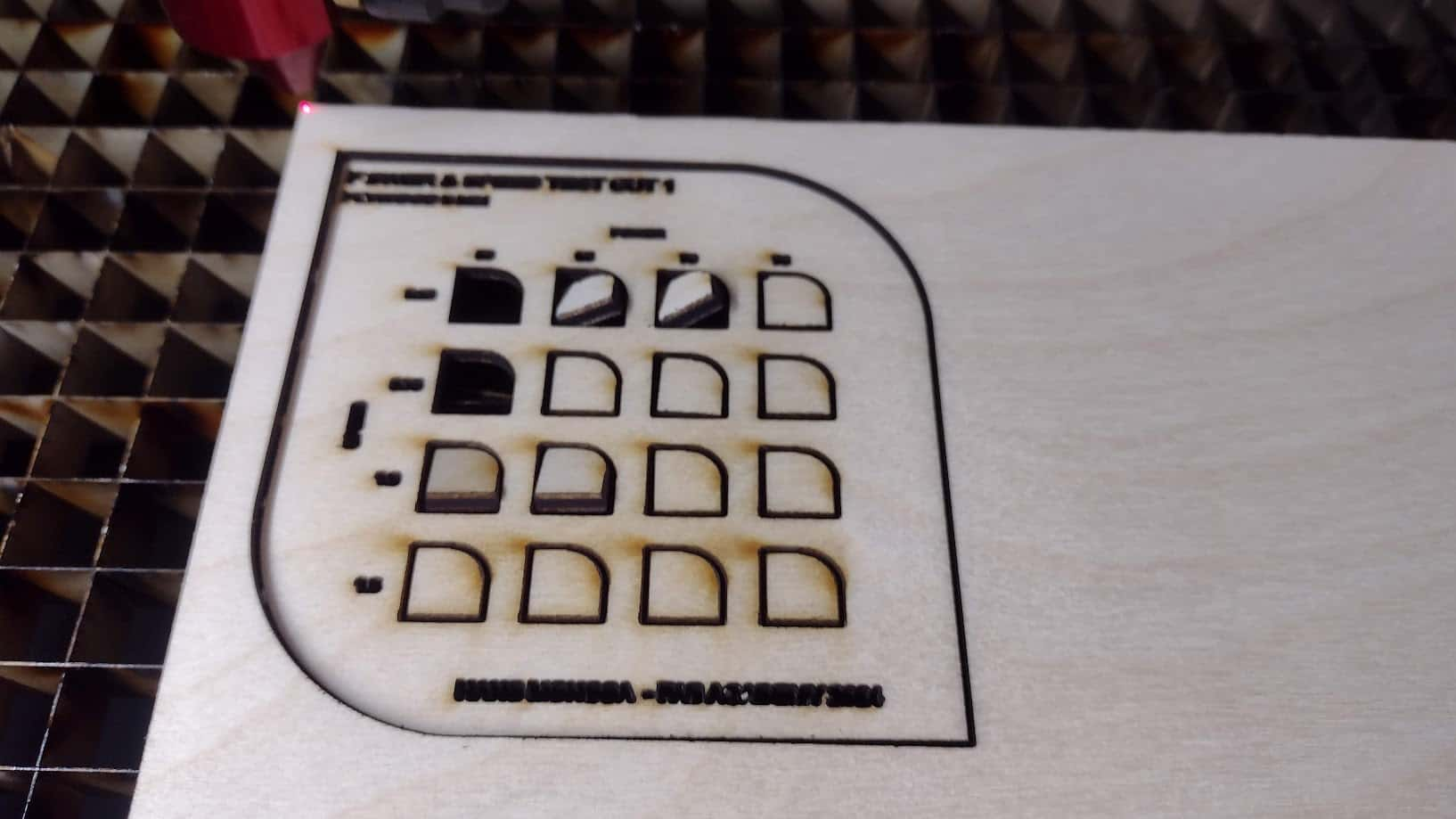
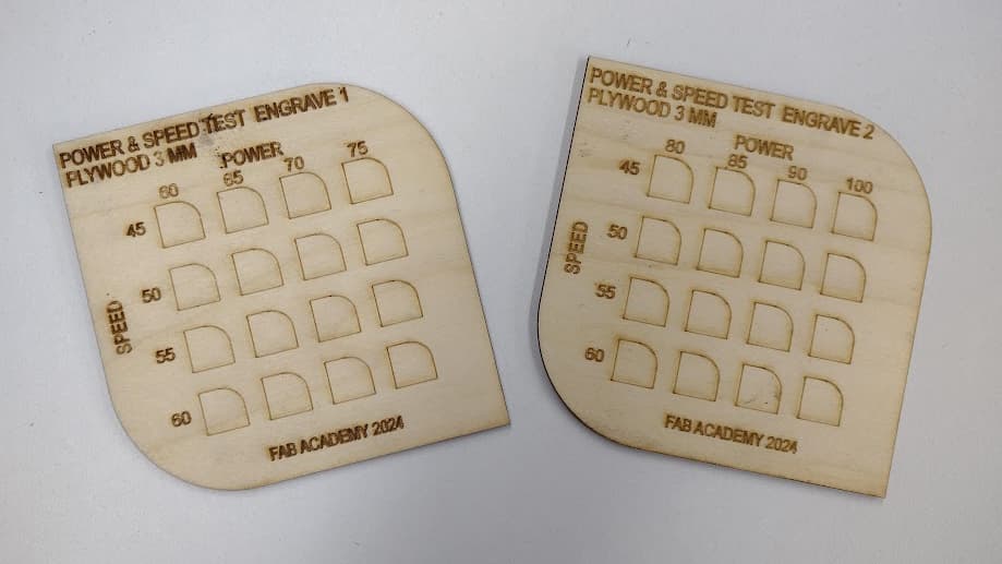
After configuring each value table, we can see the results of the laser cutting and engraving in each of them. At first, we had problems with the scale since the board was very small and the letters did not come out well. So we had to enlarge the tables and configure everything again. Here is a photo of the first test.
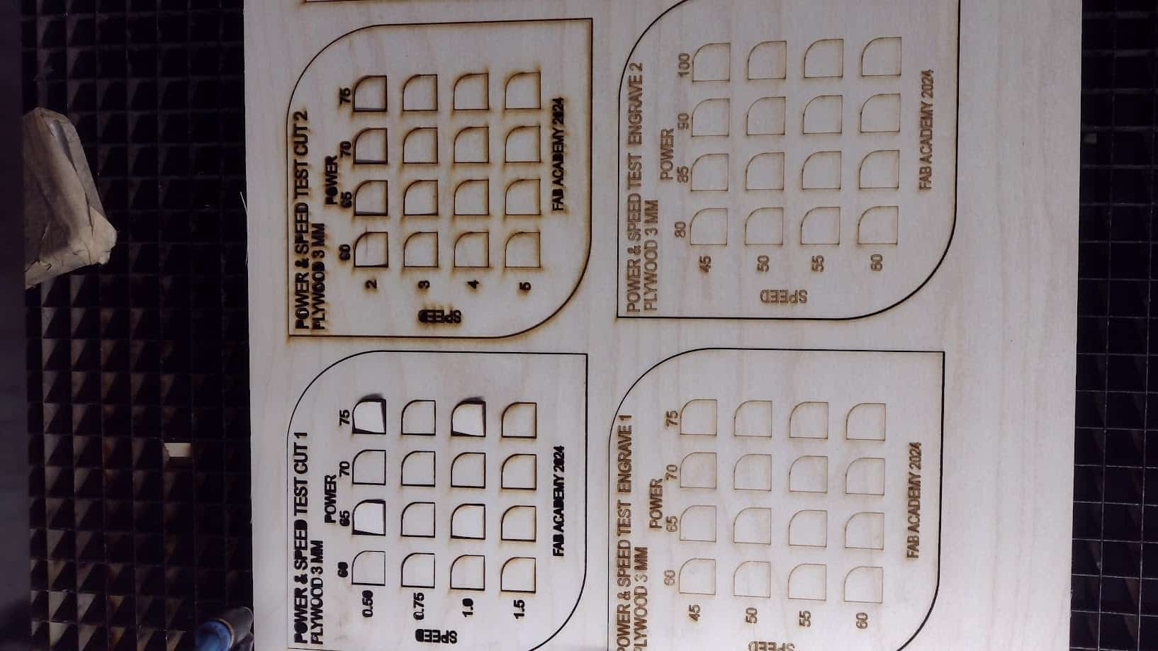
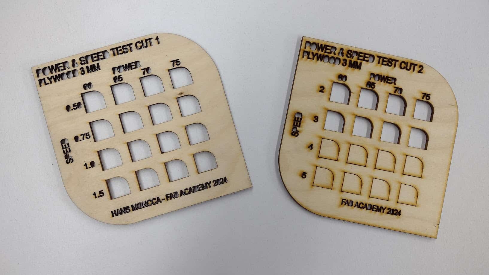
After changing the entire table configuration, we started cutting again and this time it turned out the way we wanted. It can be seen that the tables now do not present errors and the data is visible.
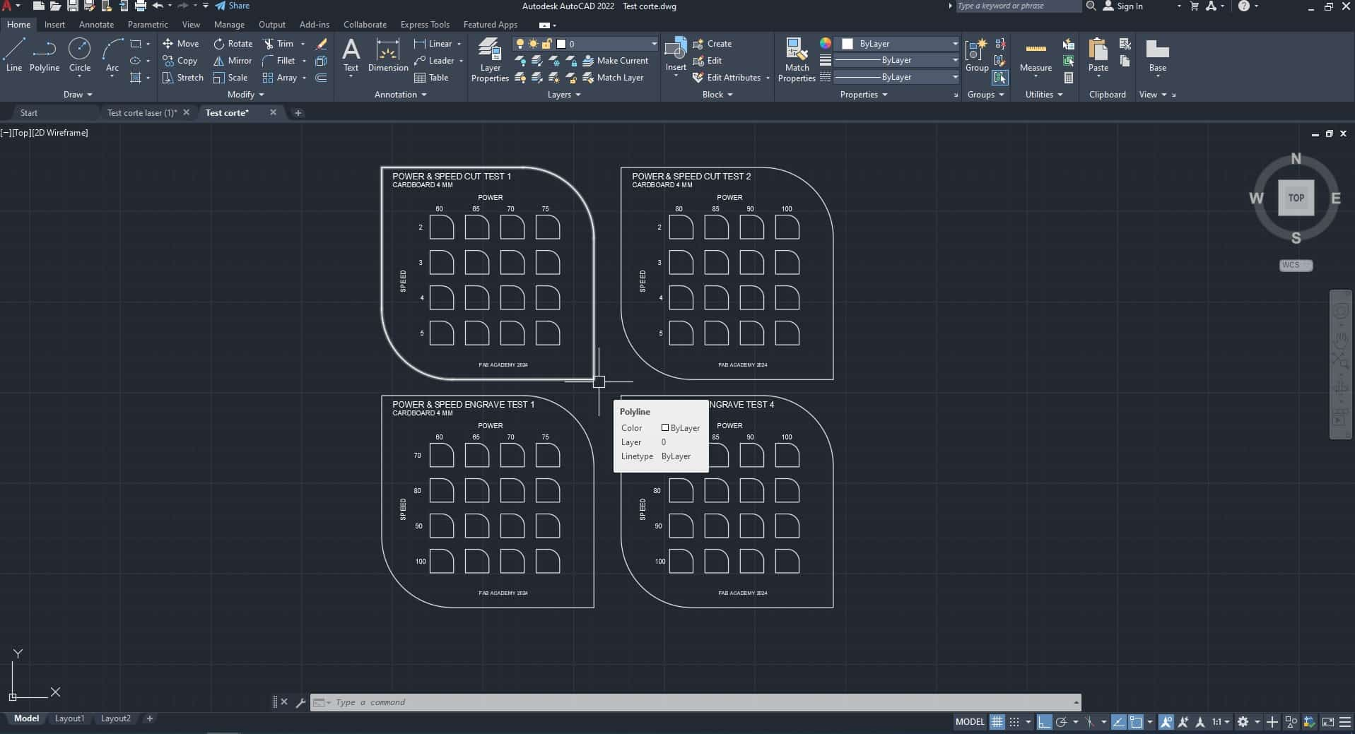
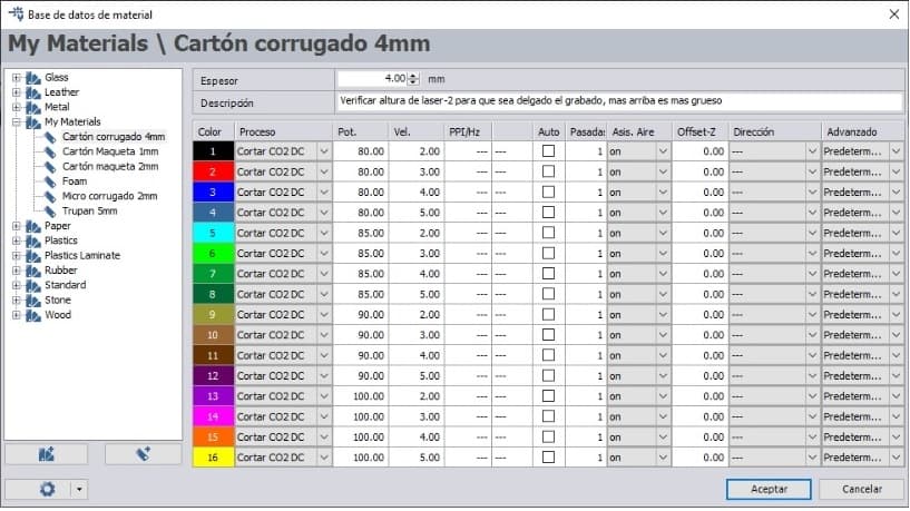
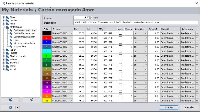
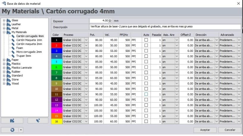
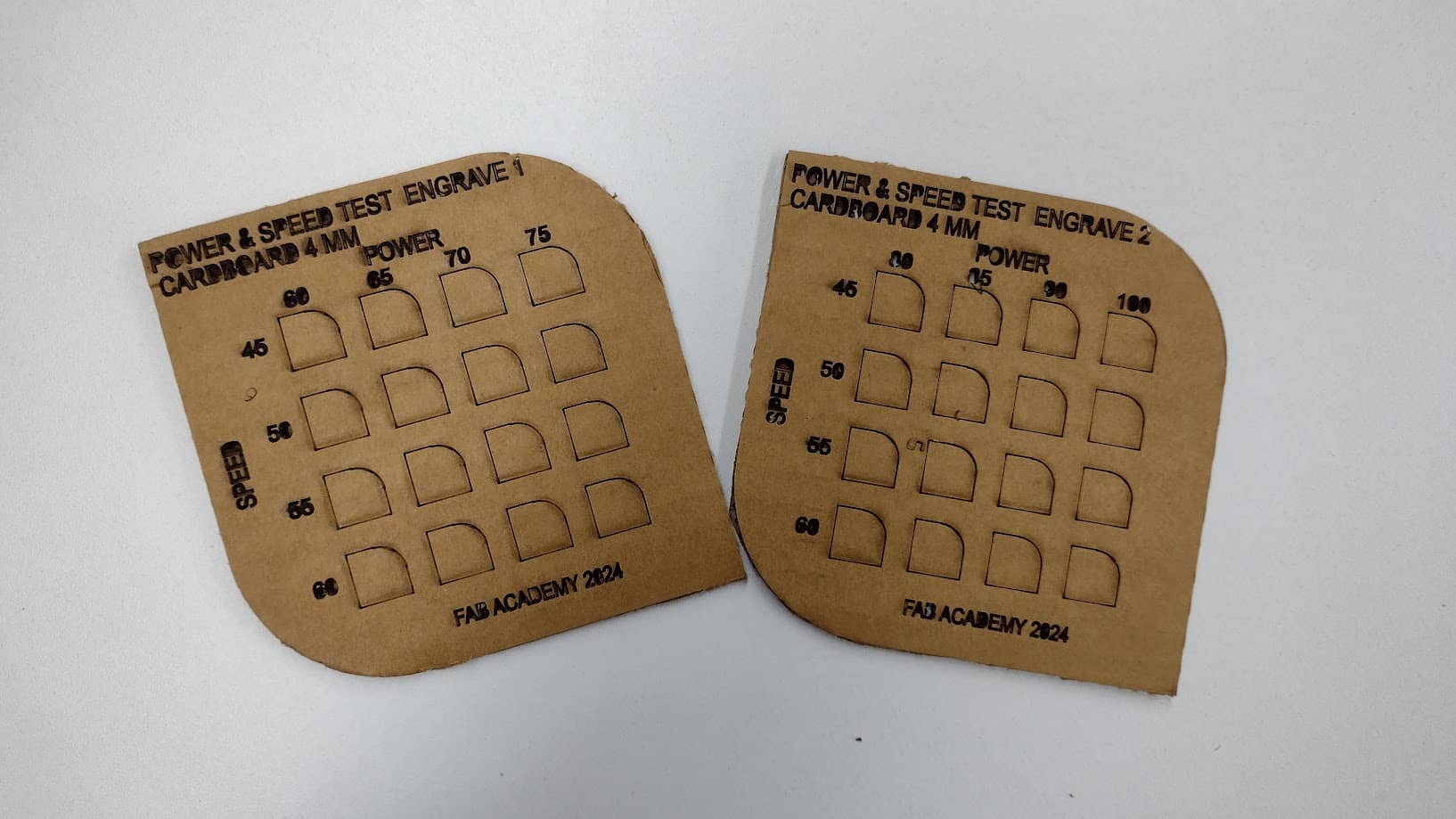
Now we start working with the 4 mm CARDBOARD where we configure their respective values for each board to see the difference between them in cutting and engraving.
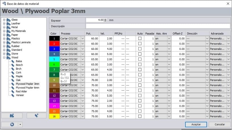
Here we had a problem, when cutting with these laser power and speed characteristics, suddenly we started to smell smoke and the cardboard was on fire. The very slow machine and the very high power meant that the cardboard caught fire, here is proof of it.
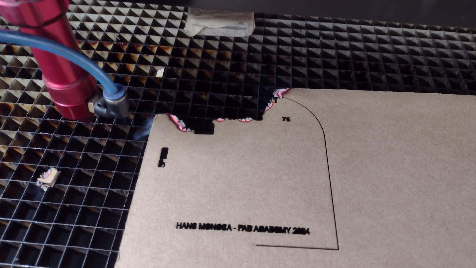
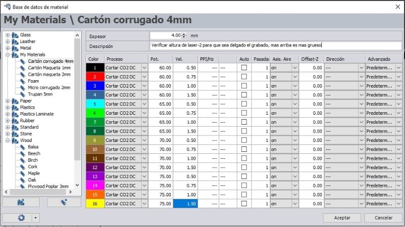
So we had to change all the board settings and increase the speed further to avoid fires in the FAB LAB. So now I show you the screenshots of the values that were used for the 4 mm CARDBOARD.
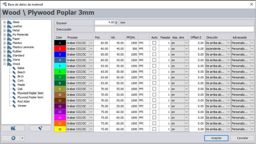
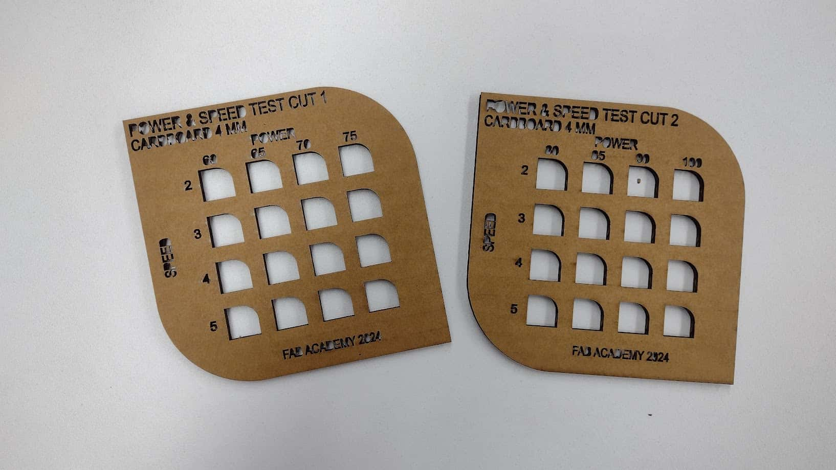
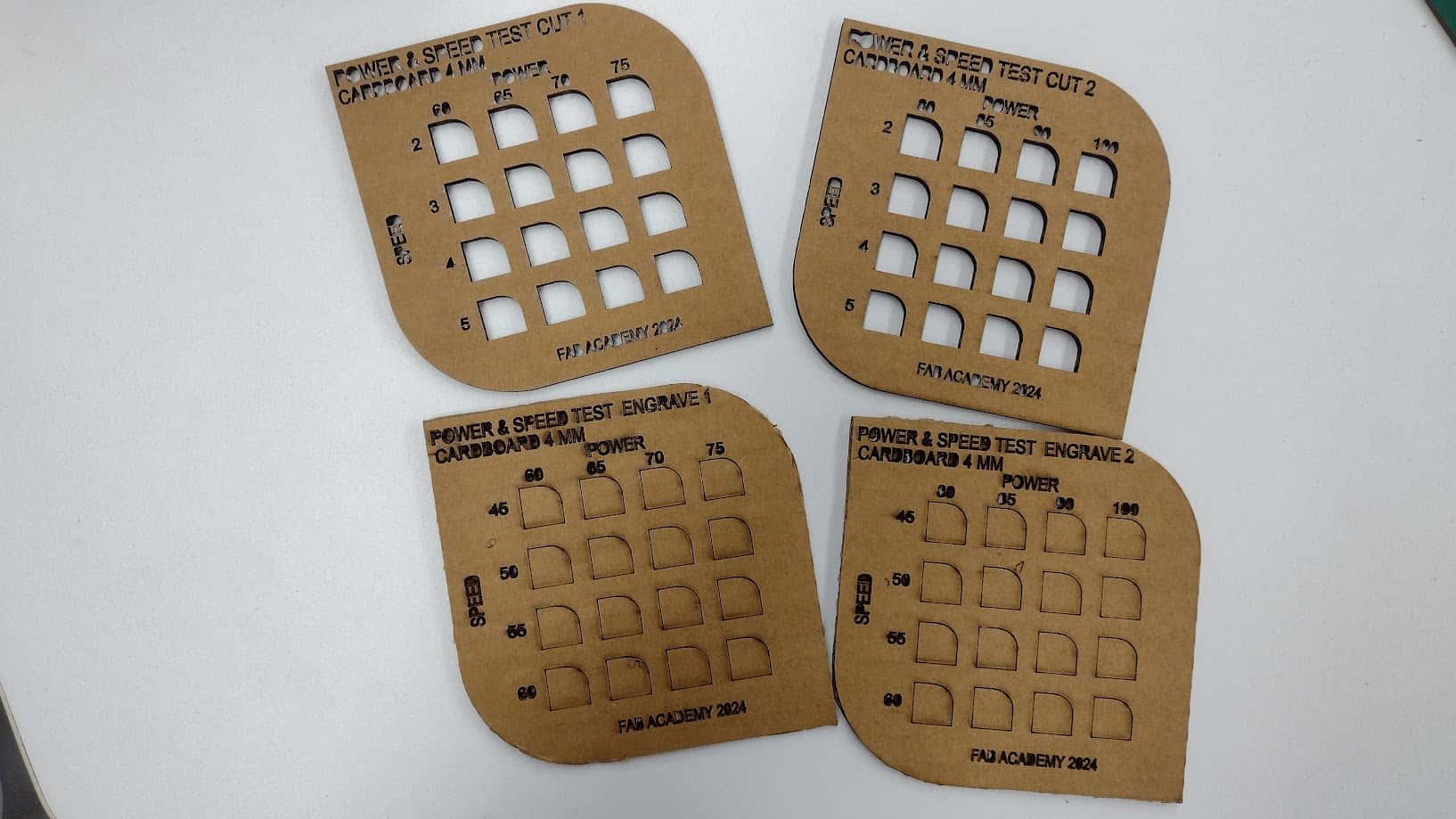
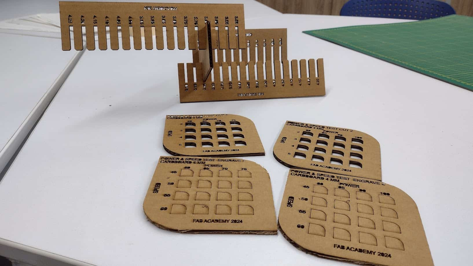
After having all the configuration ready, we proceed to cut and engrave each table according to the characteristics and values indicated. Here the results:
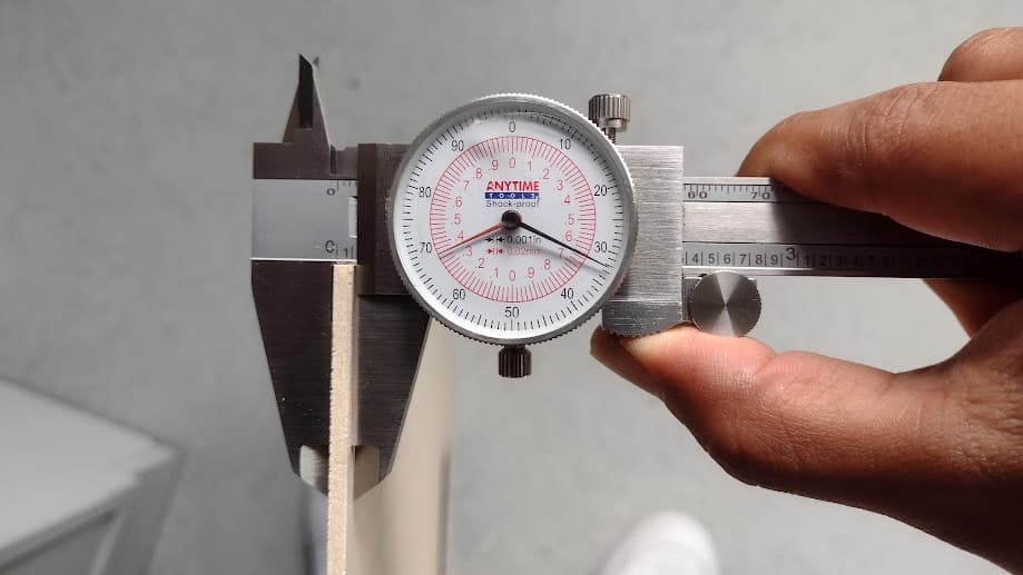
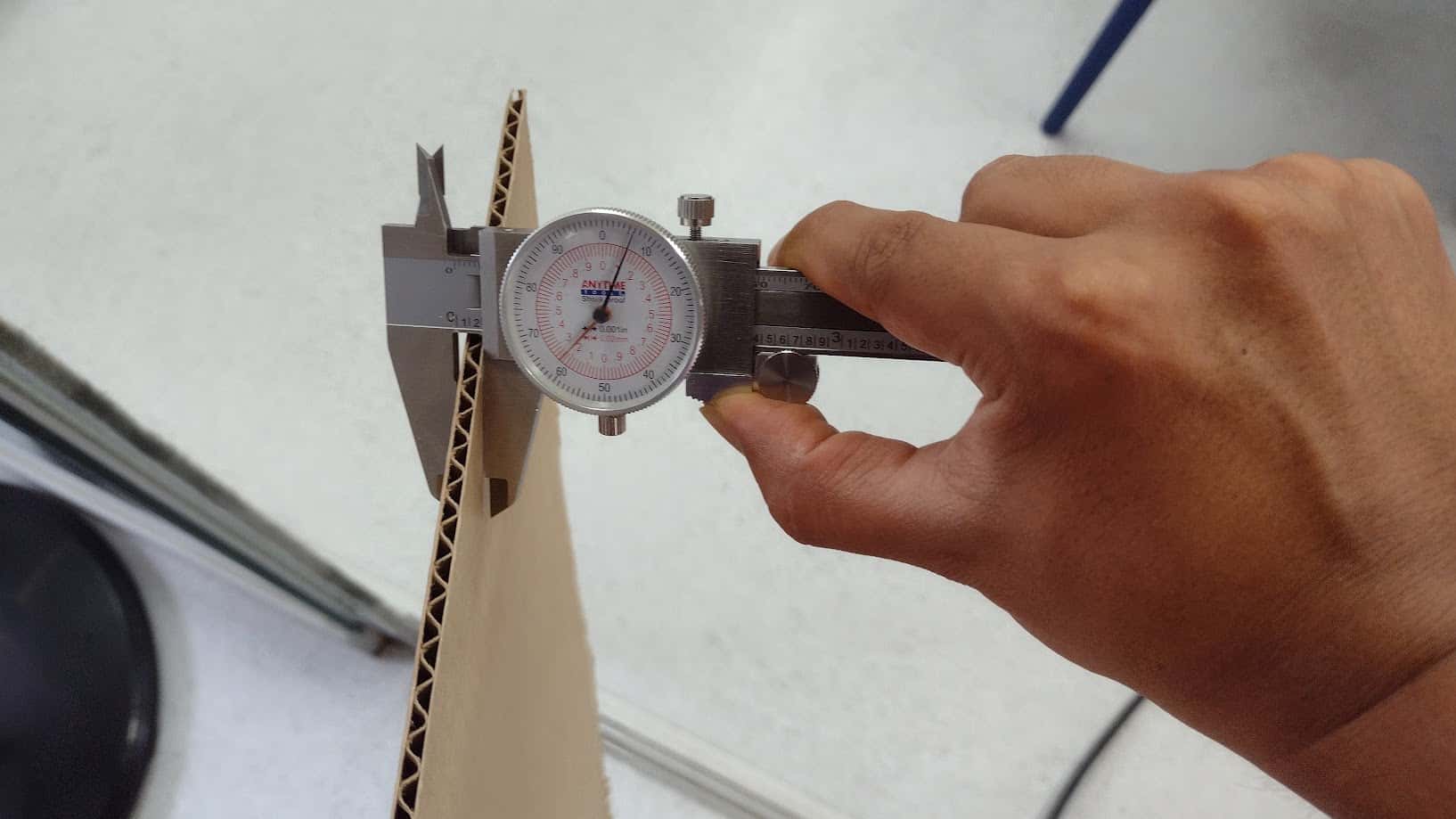
STEP 3: PRESSURE TEST AND KERF
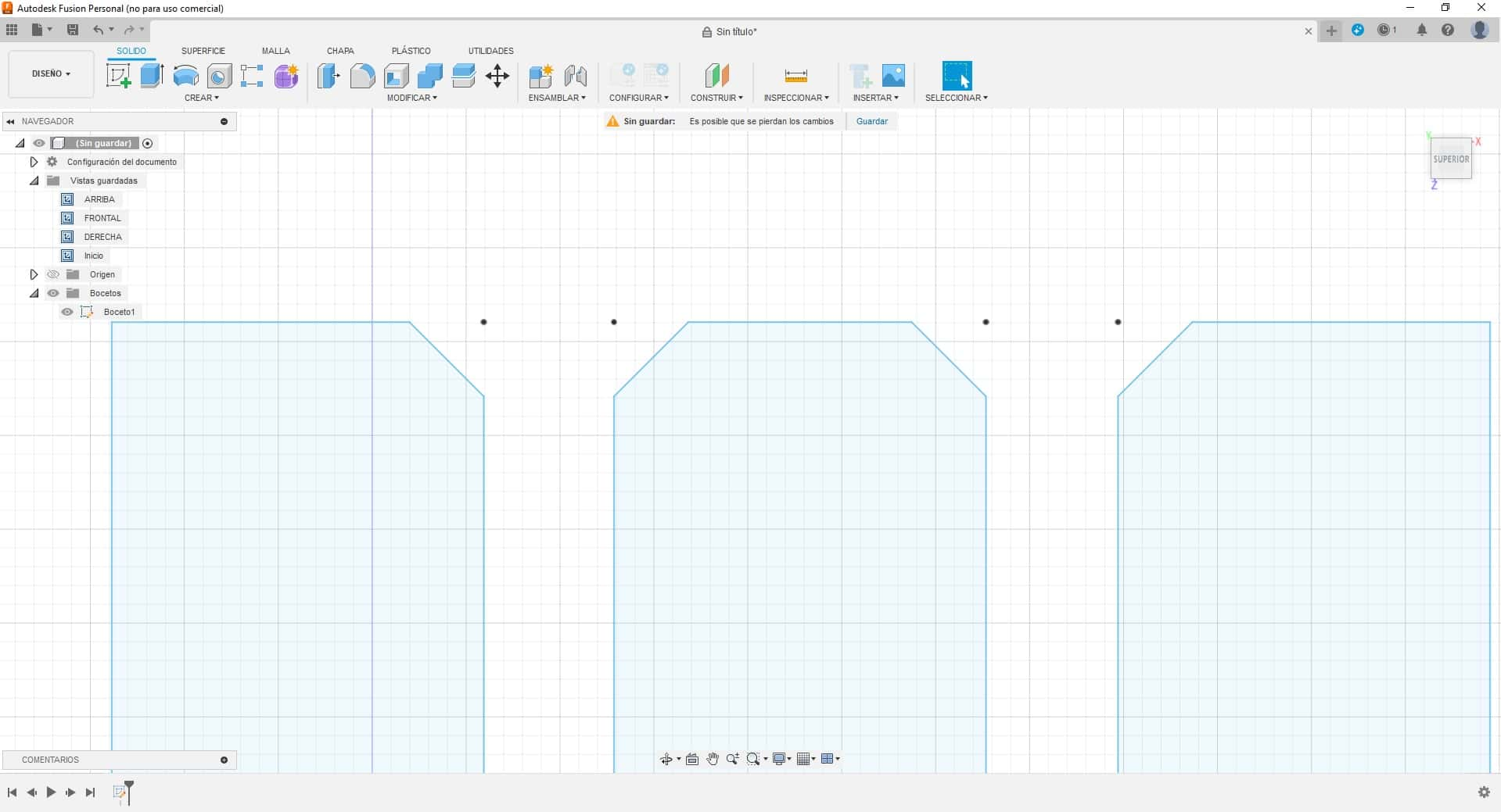
Now we will do the pressure test of cardboard and plywood. To do this, we design the piece with FUSION 360, where we make a template with several sockets of different sizes. The actual measurement of the cardboard is 4 mm and the plywood is 3 mm. Now we will make “the comb” that goes a few millimeters more and less according to the width of the material to find the exact width to achieve the pressure of each material.
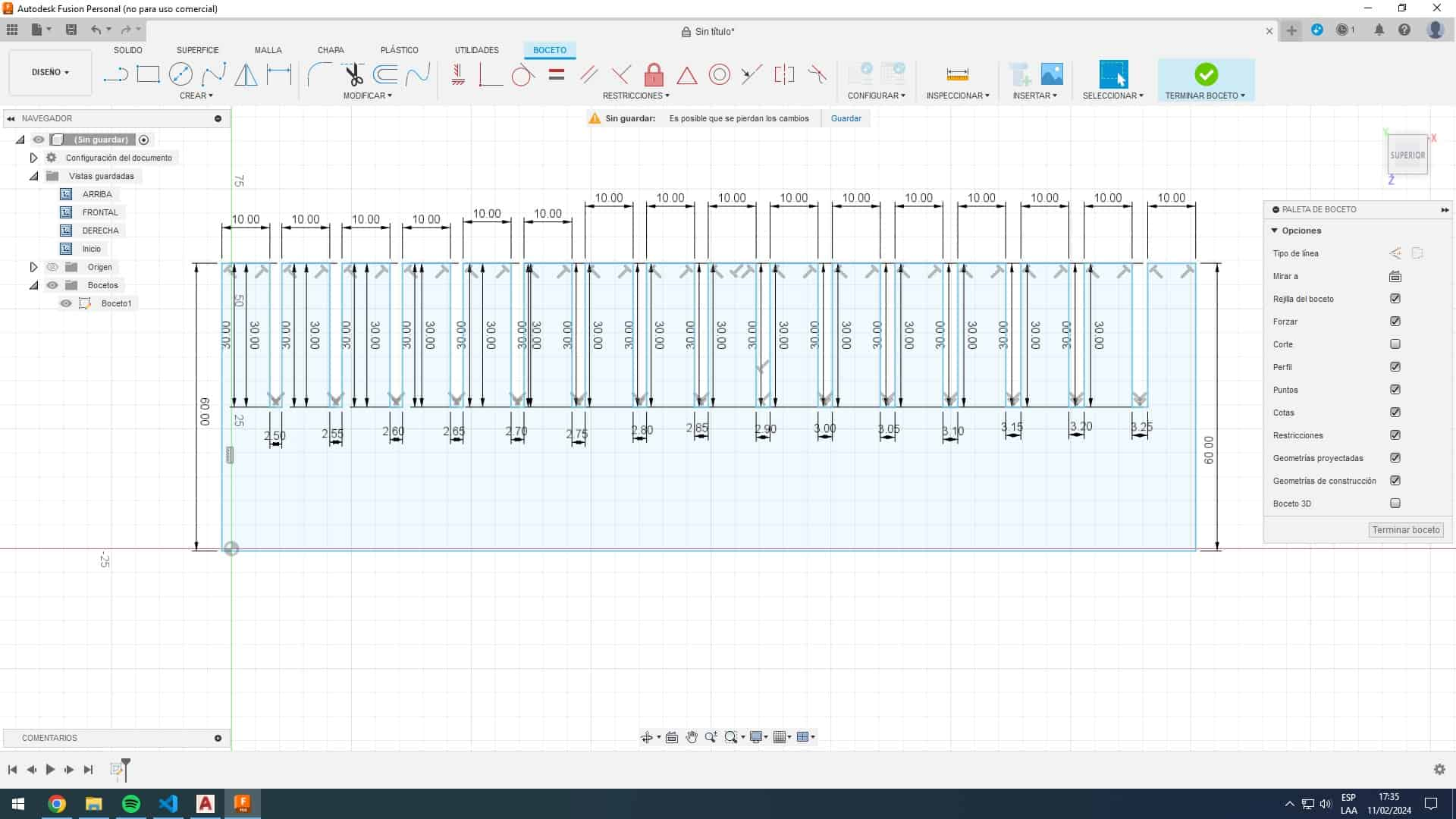
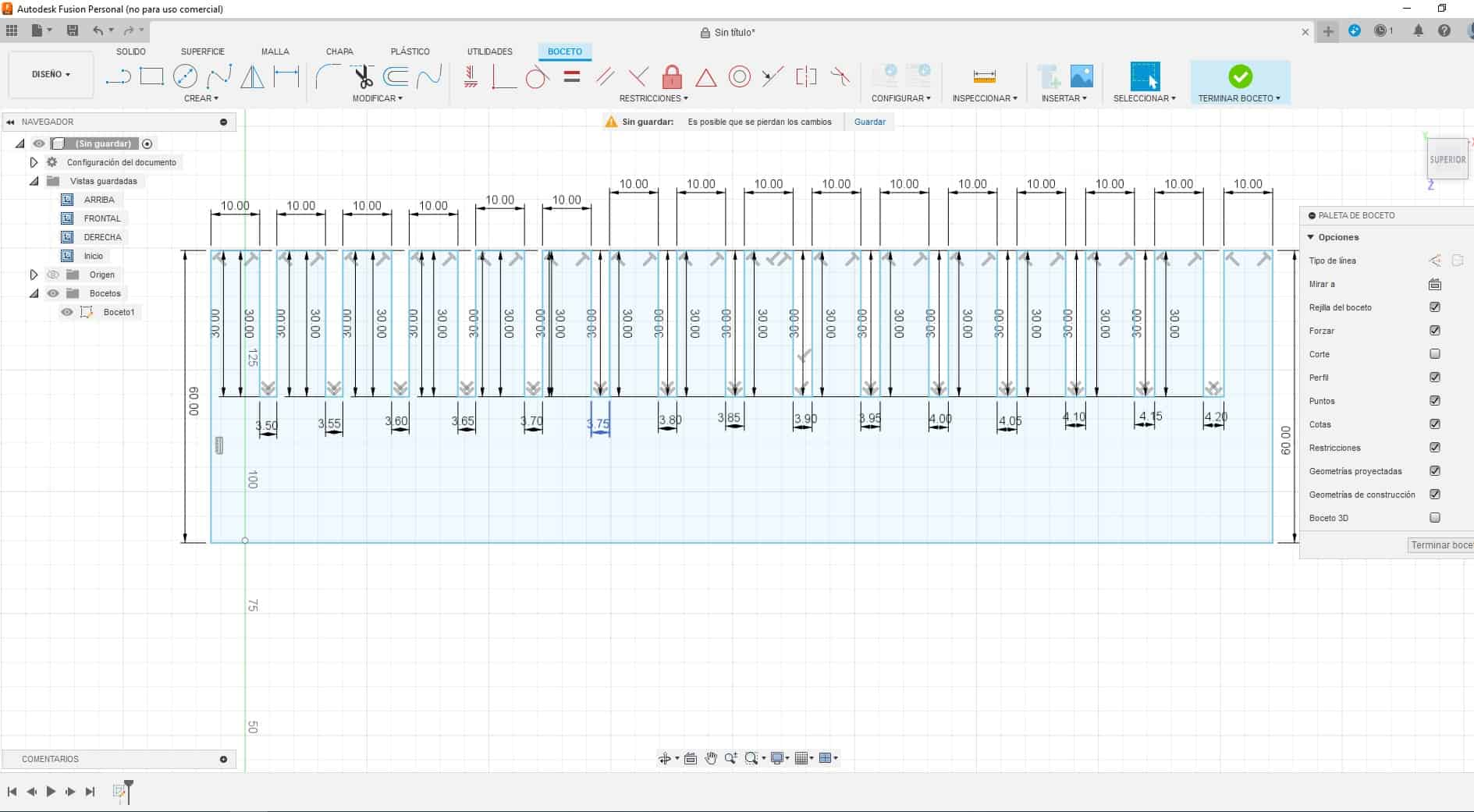
After modeling each “COMB” according to the material we are going to work with, we went to the INKSCAPE program to place the numbers that belong to each cut and be able to laser cut.
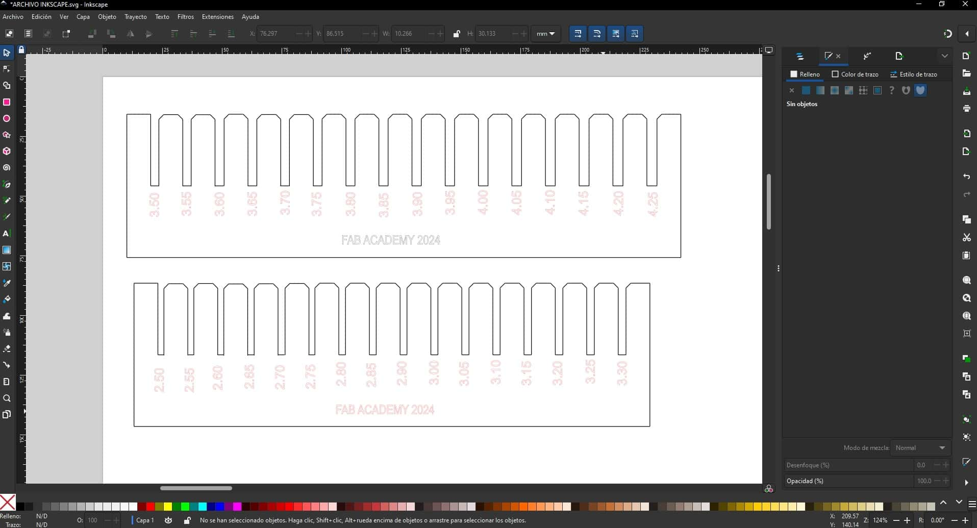
Let's remember that we have to make a “CHAMFER” in the corners so that when testing the pressure and the kerf, the material is not damaged and the tips are not damaged quickly. For this reason, it is advisable to make a “CHAMFER” in the corners.
Here I show the achieved cut of the KERF of the laser cutter to know the true adjustment of each material and thus be able to carry out the following assignment of the parametric design.
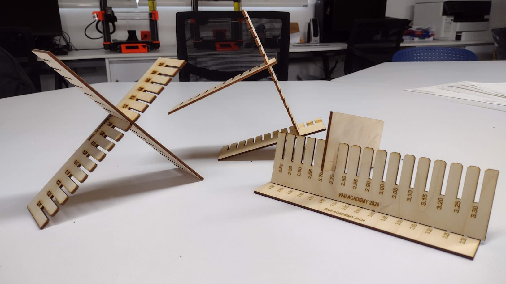
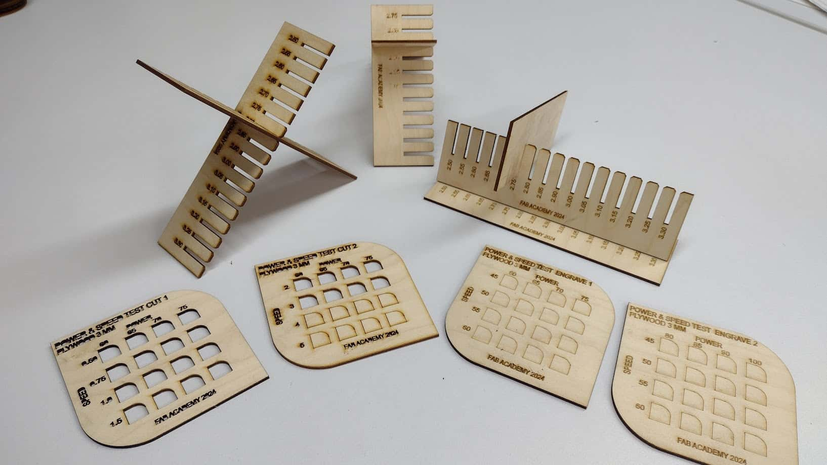
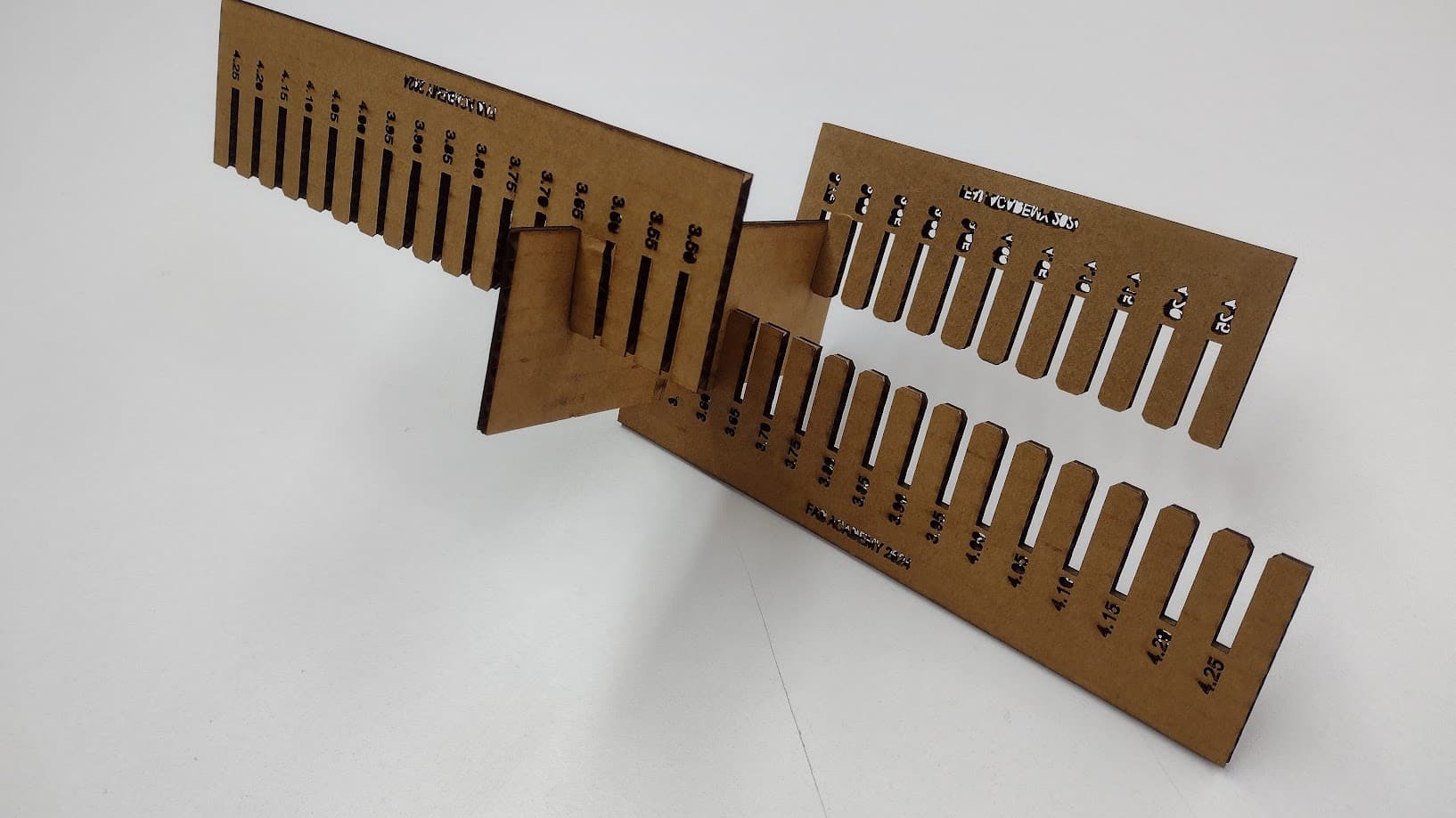
There were some problems with the KERF tests since we had problems with the engraving mainly of the section numbers and therefore we had to laser cut several “COMBS” but in the end we were able to find the fit of each material. Where we can conclude that:
Actual plywood thickness: 3.00 mm - actual fit: 2.75 mm = PLYWOOD cut: 0.25 mm
Actual cardboard thickness: 4.00 mm- actual fit: 3.65 mm = CARDBOARD cut: 0.35 mm
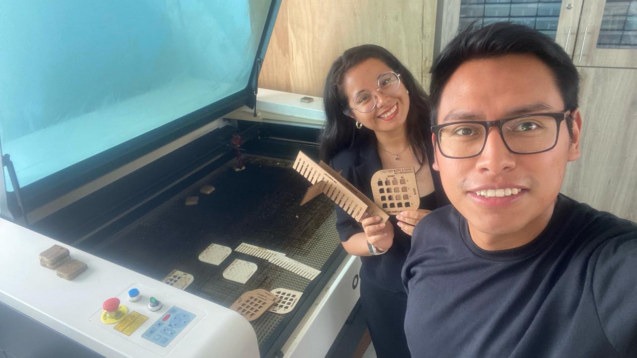
Here are some photos of the group work with my friend Maryori, where it was a day of learning, with mistakes and successes to achieve the grupal assignment.
INDIVIDUAL ASSIGNMENT
PARAMETRIC DESIGN
PARAMETRIC DESIGN WITH FUSION 360
For the individual task we will use 4 mm CARDBOARD as material and the FUSION 360 software, since it provides us with a table to modify the parameters of what we draw as a sketch and from there, we modify according to the values obtained such as the KERF value that in this material it is 3.65 mm.
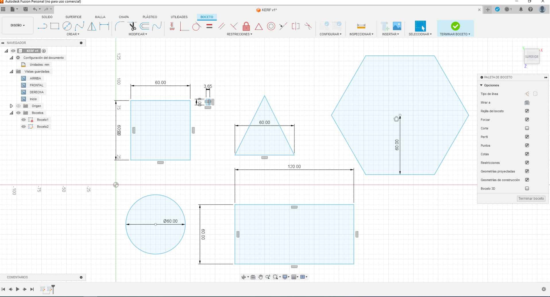
After drawing the basic shapes of the parametric design, the pressure cut is made, with a width of 3.65 in accordance with the evaluation made in what was explained above and the “CHAMFER” is also made so that when playing with the figures they can have a better grip and we do not have problems when using it or the corners deteriorating.
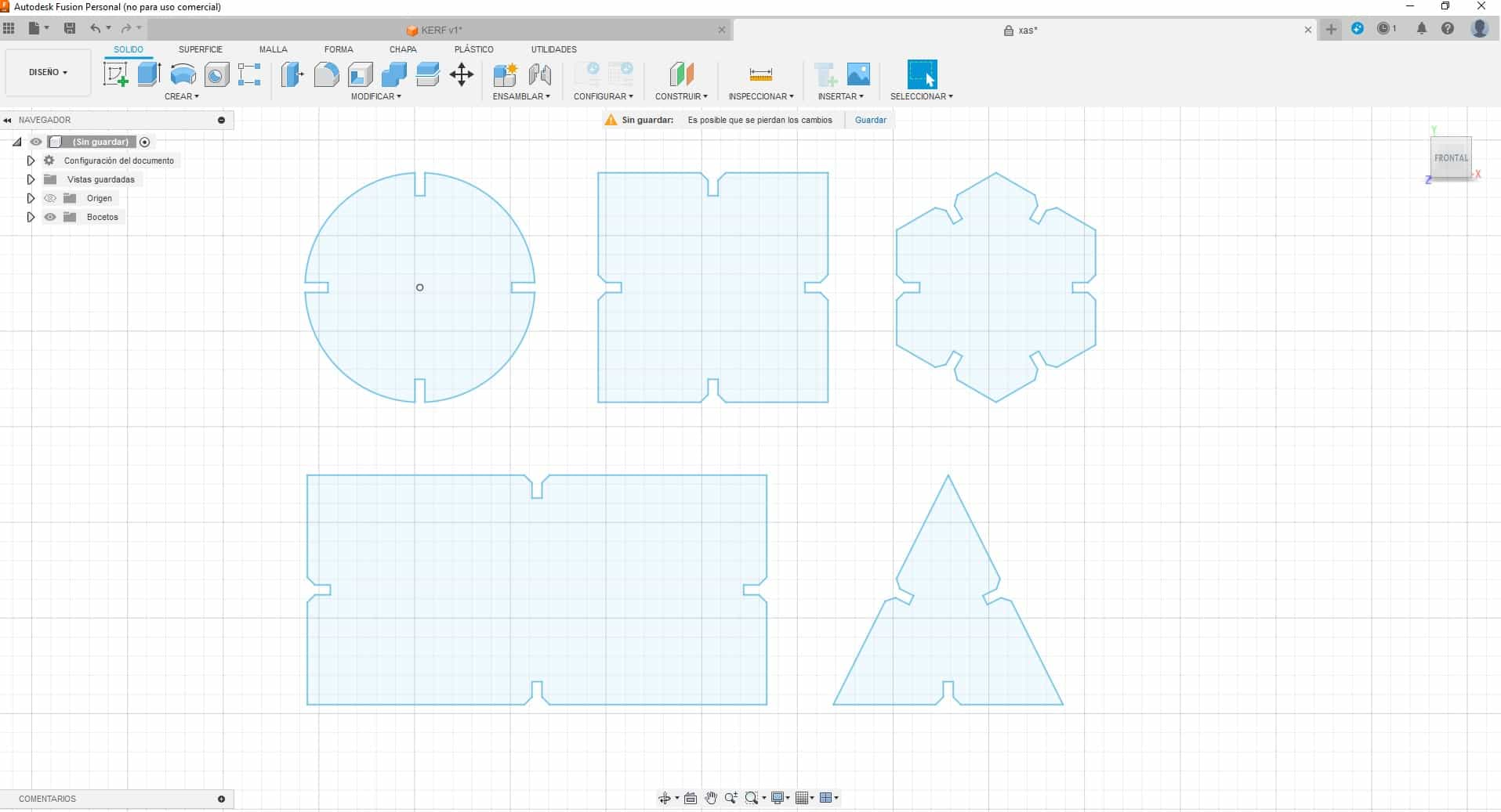
Now we proceed to export as a DXF file since in AutoCAD it is easier to multiply the objects and then be able to laser cut the figures with the required dimensions.
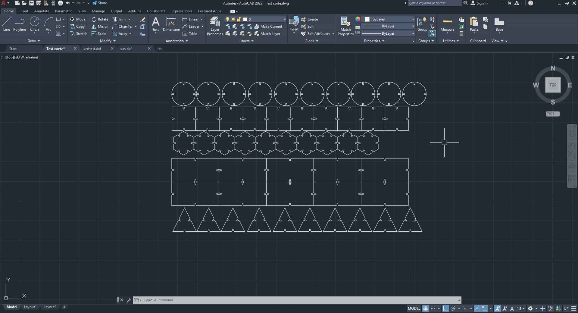
We proceed to laser cut and we can see that, with the values test carried out previously, one of them was chosen to be placed as power and speed and thus achieve a clean cut. Here I show the section of the parametric figures.
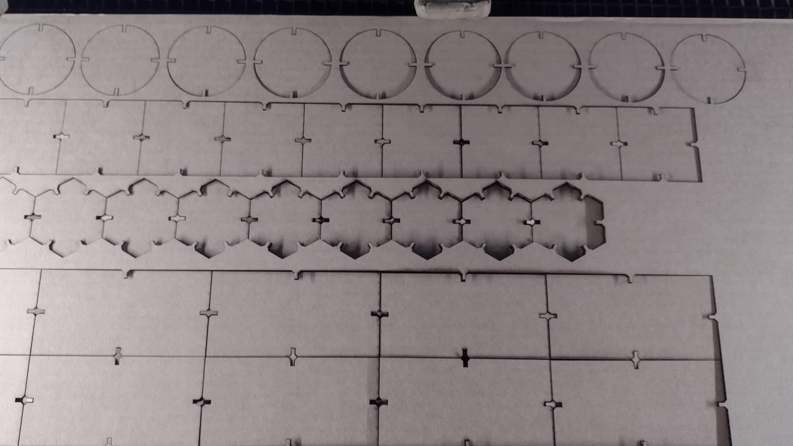
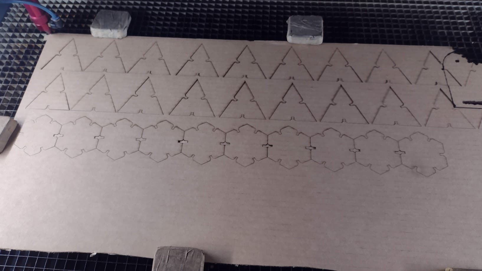
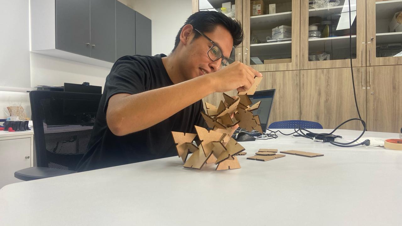
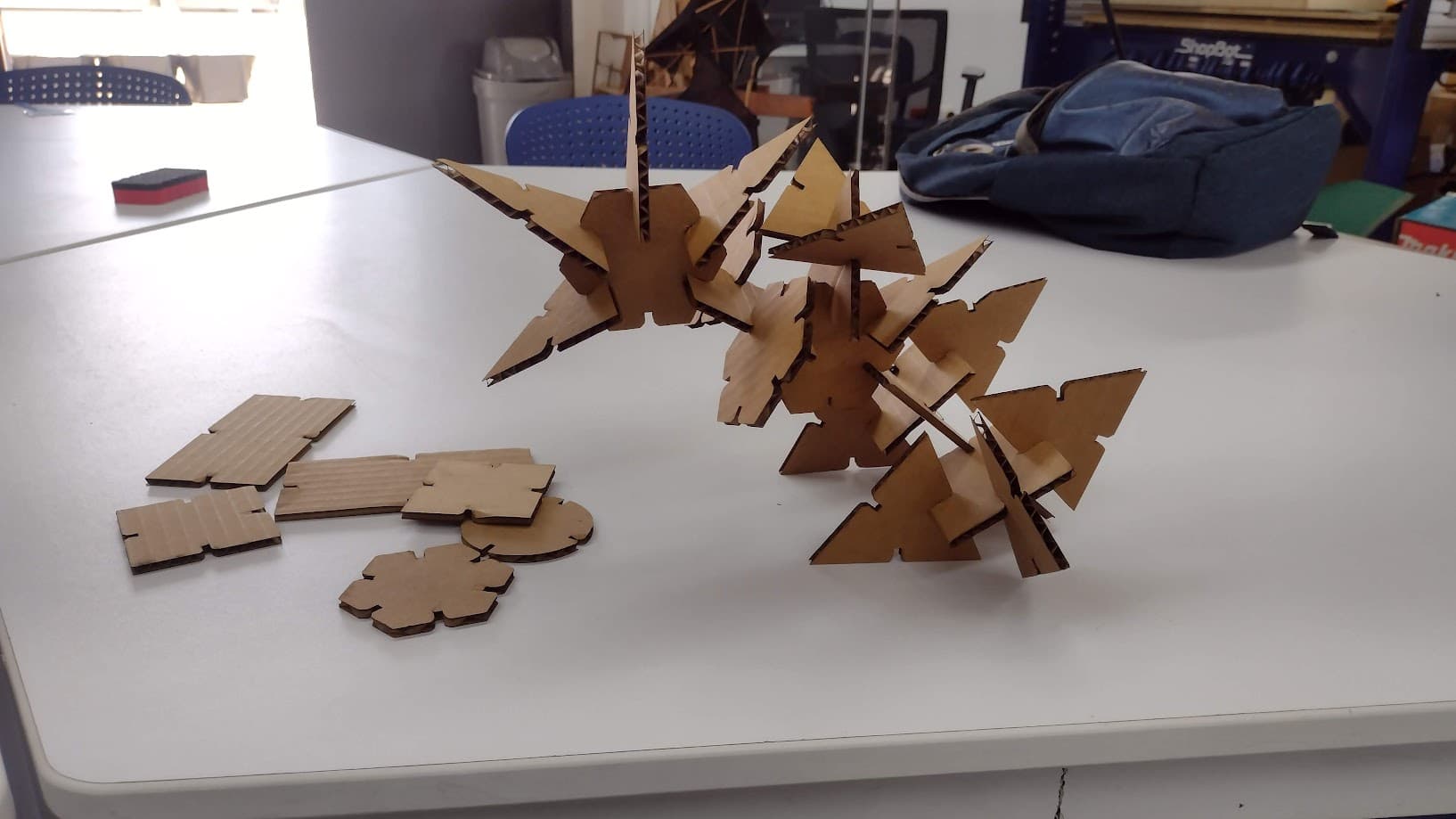
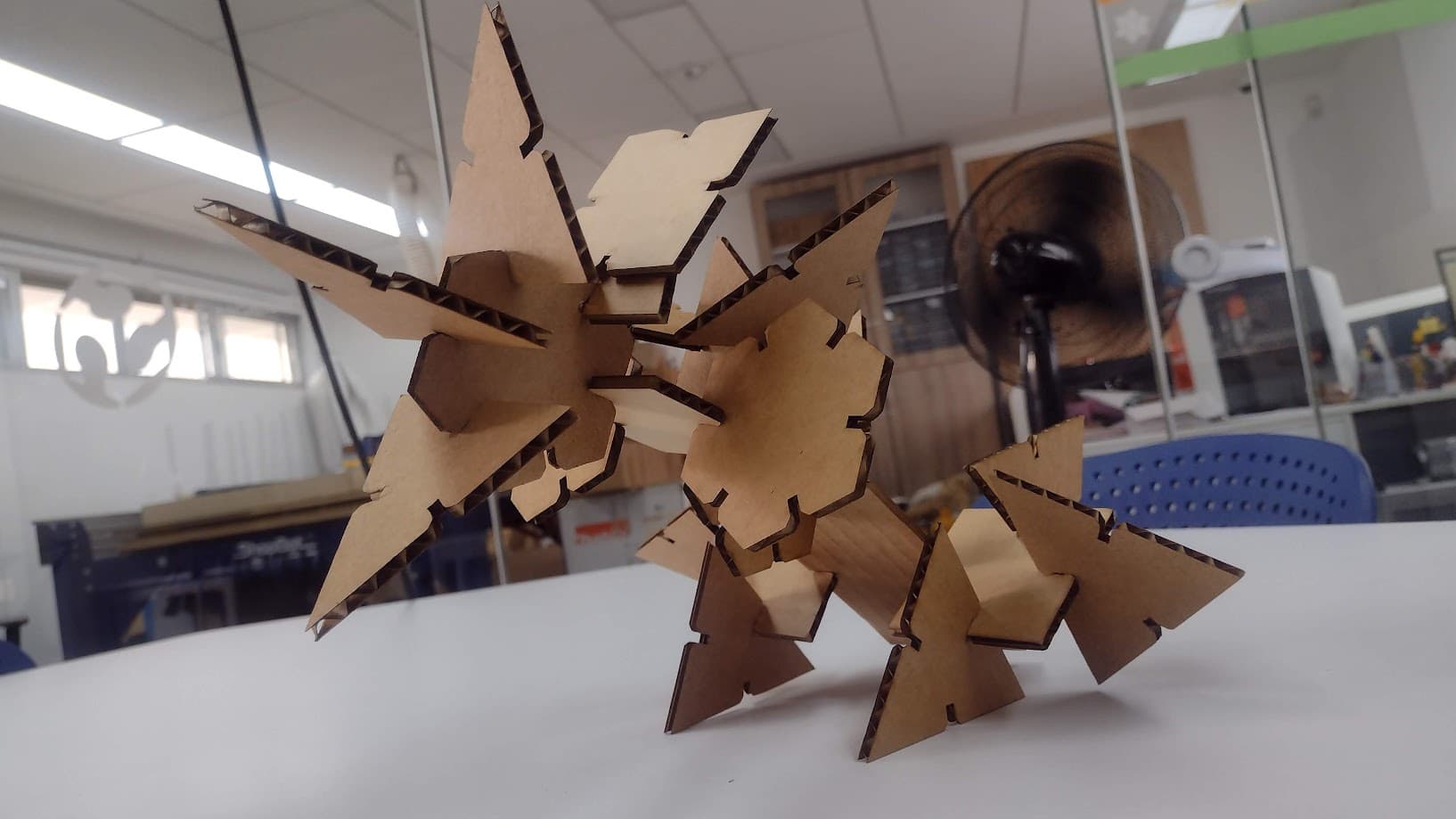
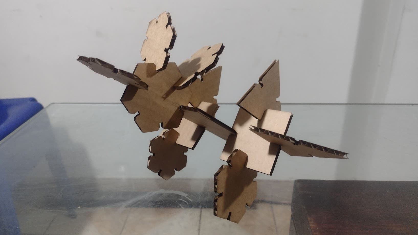
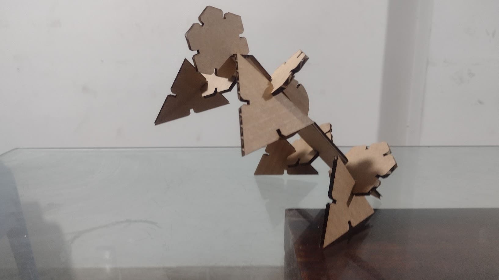
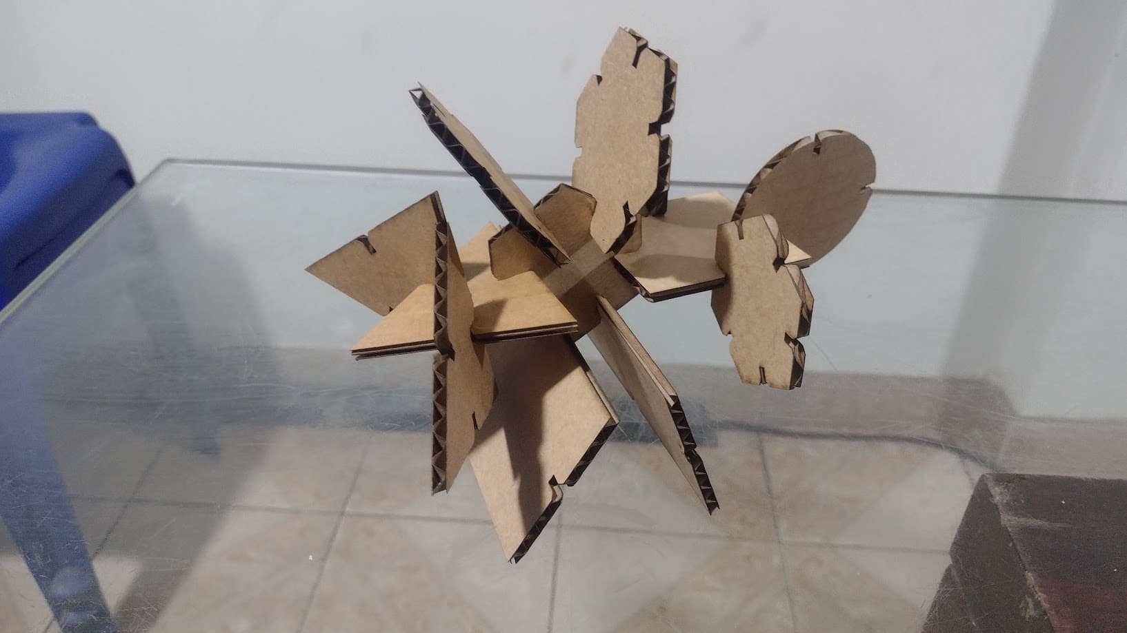
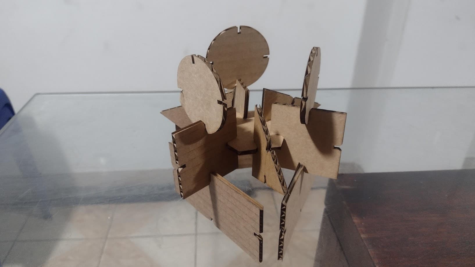
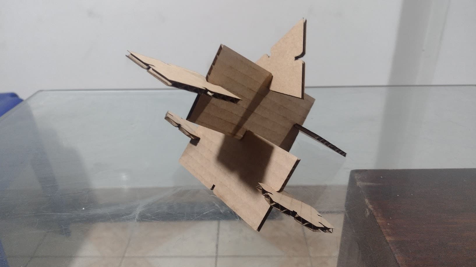
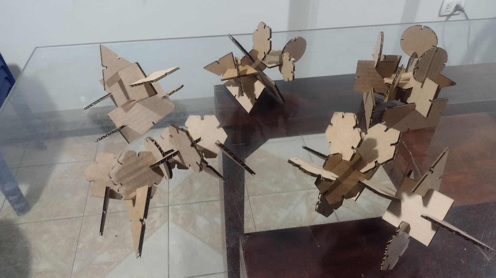
And with these figures the idea is to manage to create different shapes or objects that we can achieve. Here I show a gallery of the figures that I was able to achieve with these parametric shapes. Some cousins supported me here because when I took them home, they wanted to play with the figures and we were able to make different shapes with a lot of imagination.
VINYL CUTTING
VINYL CUTTER
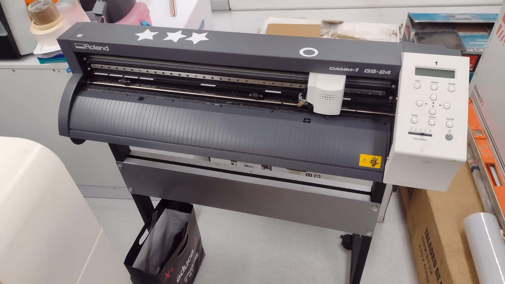
The vinyl cutter that we have at the Universidad Cientifica del Sur is the ROLAND GS 24. Which has the following technical specifications:
| CUTTING SPEED | 10 - 850 mm/s |
|---|---|
| CUTTING FORCE | 30 - 500 gf |
| CUTTING WIDTH | 584 mm |
| CUTTING LENGTH | 25 m |
LOGO FAB ACADEMY - WHITE
To start making vinyl cuts I wanted to start with a simple, monochromatic design. Therefore, I chose the FAB ACADEMY logo in white. The idea is to understand the configuration of both the machine and the software. In this case we will use INKSCAPE to have the images in vectors and be able to make the cuts.
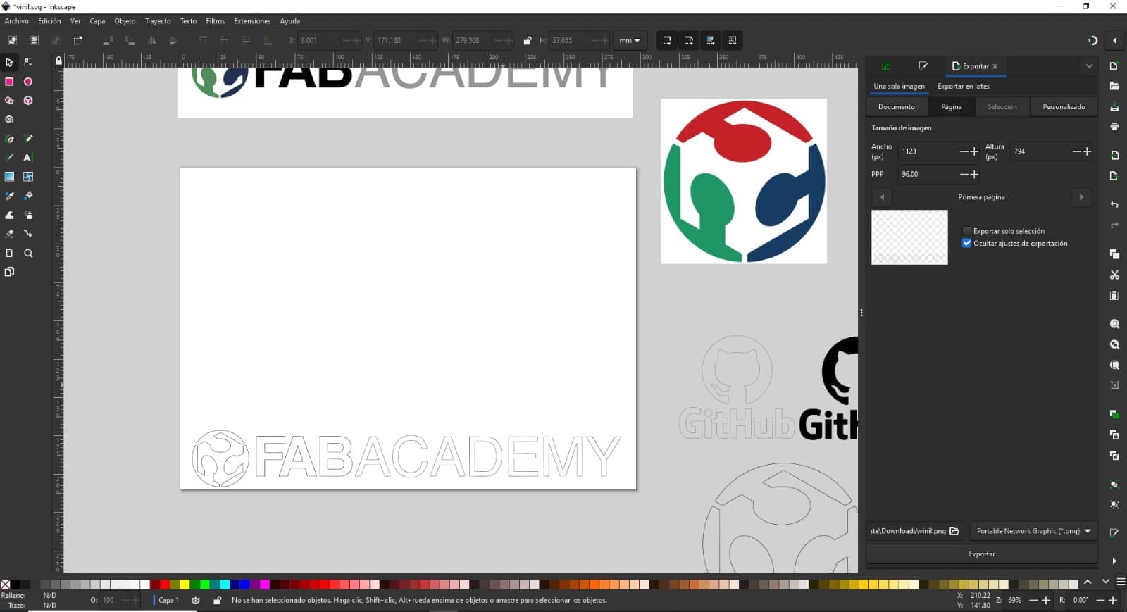
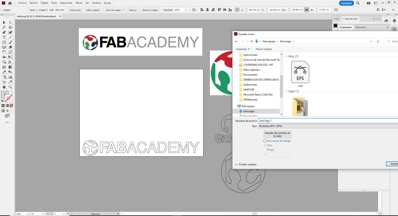
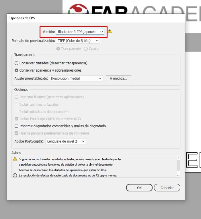
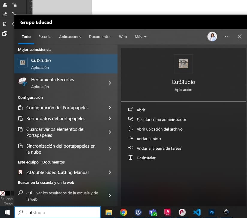
However, we had a problem with exporting the INKSCAPE file to the machine program called CUTSTUDIO. For this reason, we prefer to send the vector image to ILLUSTRATOR and from there export the image to CUTSTUDIO.
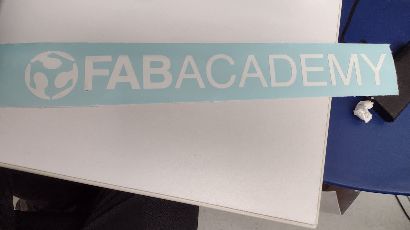
We have the FABACADEMY logo cut on the machine to see if the blade pressure is correct.
The result was good, we were able to "PEEL" the vinyl cut and obtain "CLEAN" the complete FAB ACADEMY logo.
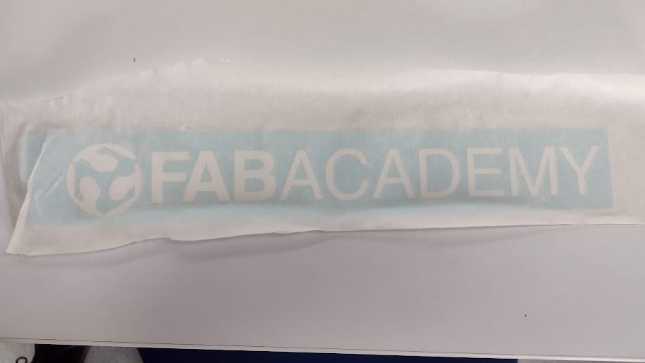
Now we paste the “TRANSFER PAPER” to obtain the logo and be able to paste it on any surface. Here with my friend Maryori we decided to make a complete logo to be able to paste on the university where we work since the objective is to turn it into a new FAB ACADEMY node.
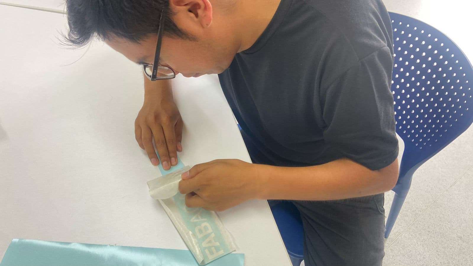
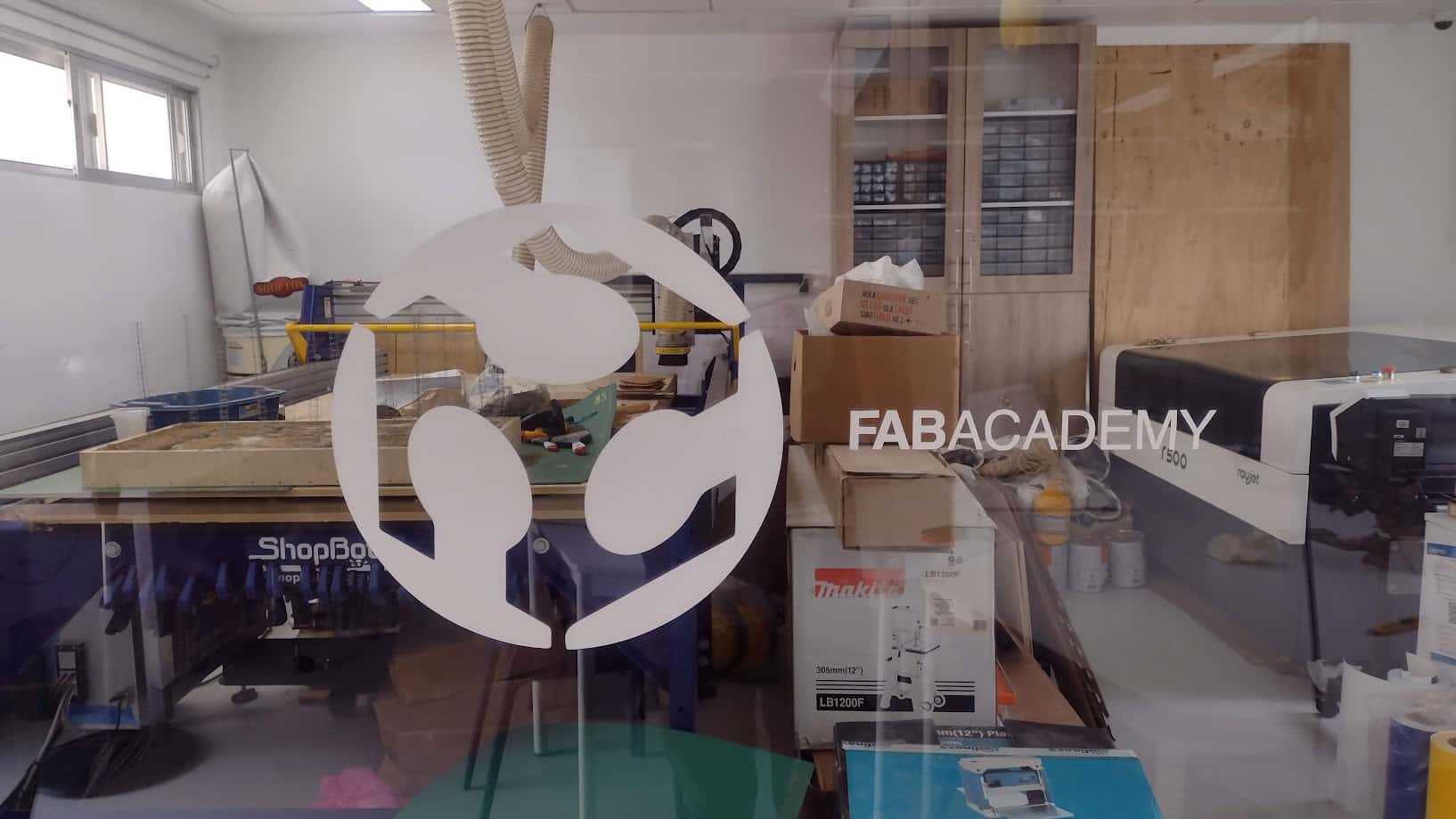
Now from the TRANSFER PAPER we can paste on any surface we want. We decided to stick it on the screen of the machinery area since it is an attractive area and here we can see the process and the result that together with my friend we were able to do.
LOGO FOR AGENDA
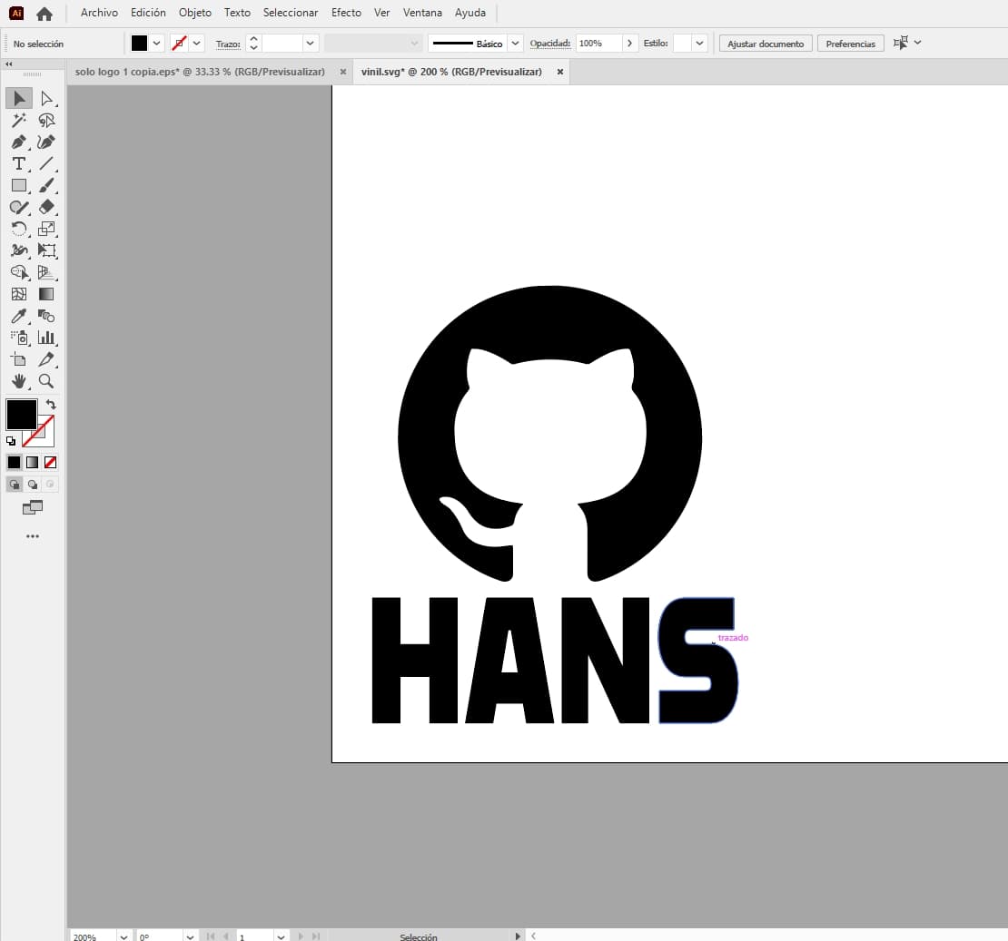
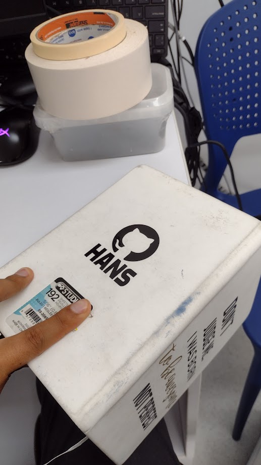
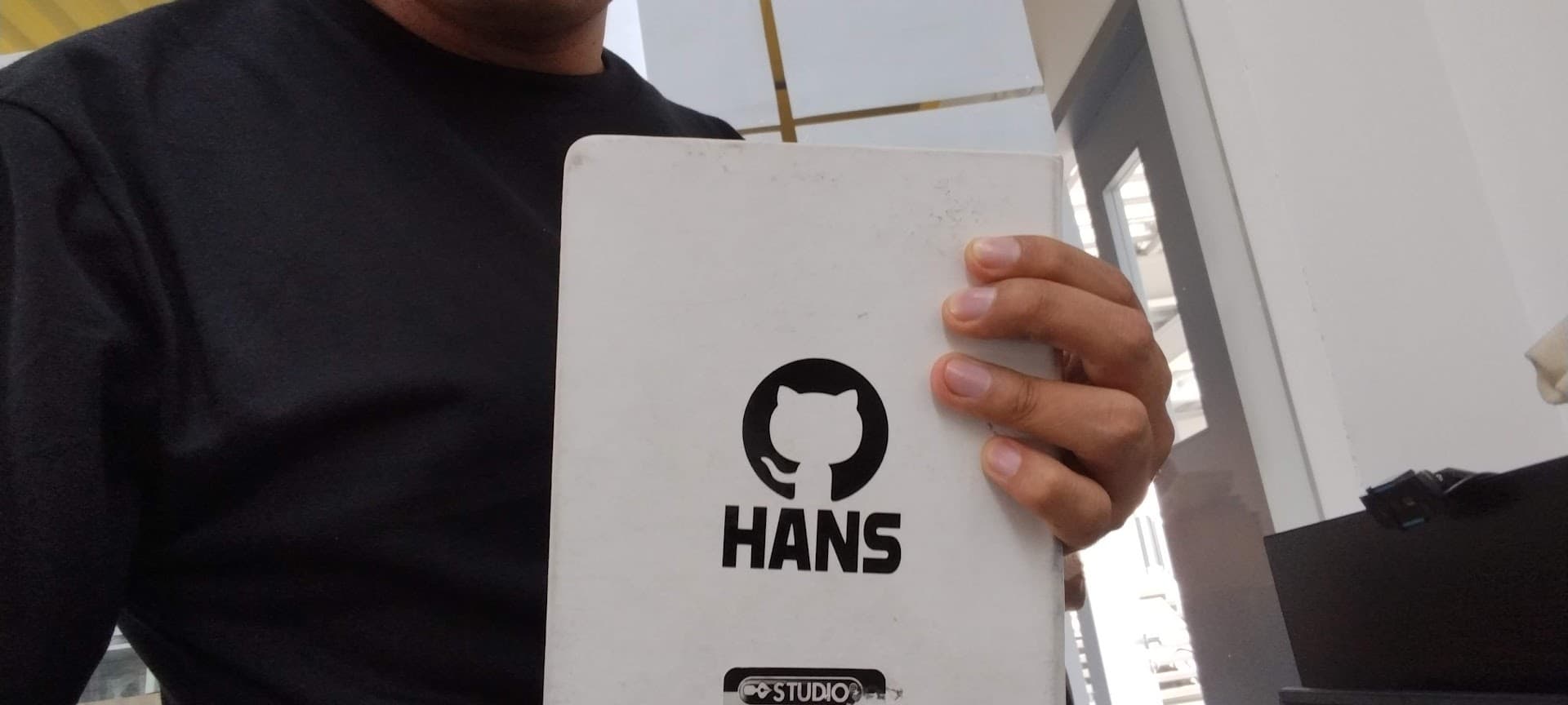
Now I wanted to make a more personal logo so I could stick it in my agenda. For this reason, I decided to take the GITLAB logo because I think the cat it has as a logo is cute. And I wanted to add my name to see if it looked good and I think it does.
First we design the logo in ILLUSTRATOR and then send it to the vinyl machine program.
Now we proceed to cut and remove all the excess vinyl to obtain the logo we designed.
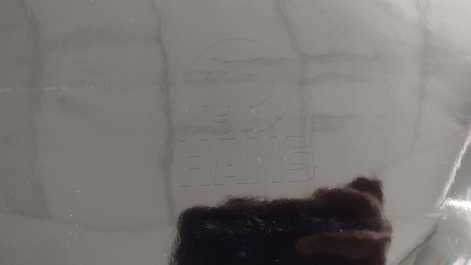
Finally, here we can see the results of the vinyl cutting that I wanted for my agenda. It looks great and the machine cuts very well to achieve the detail you are looking for.
FILES
Here you can download all the files that I have made for the following assignment: