5. Electronics production
This week’s assignment was to make and test a microcontroller development board.
Individual assignment
Make and test a microcontroller development board
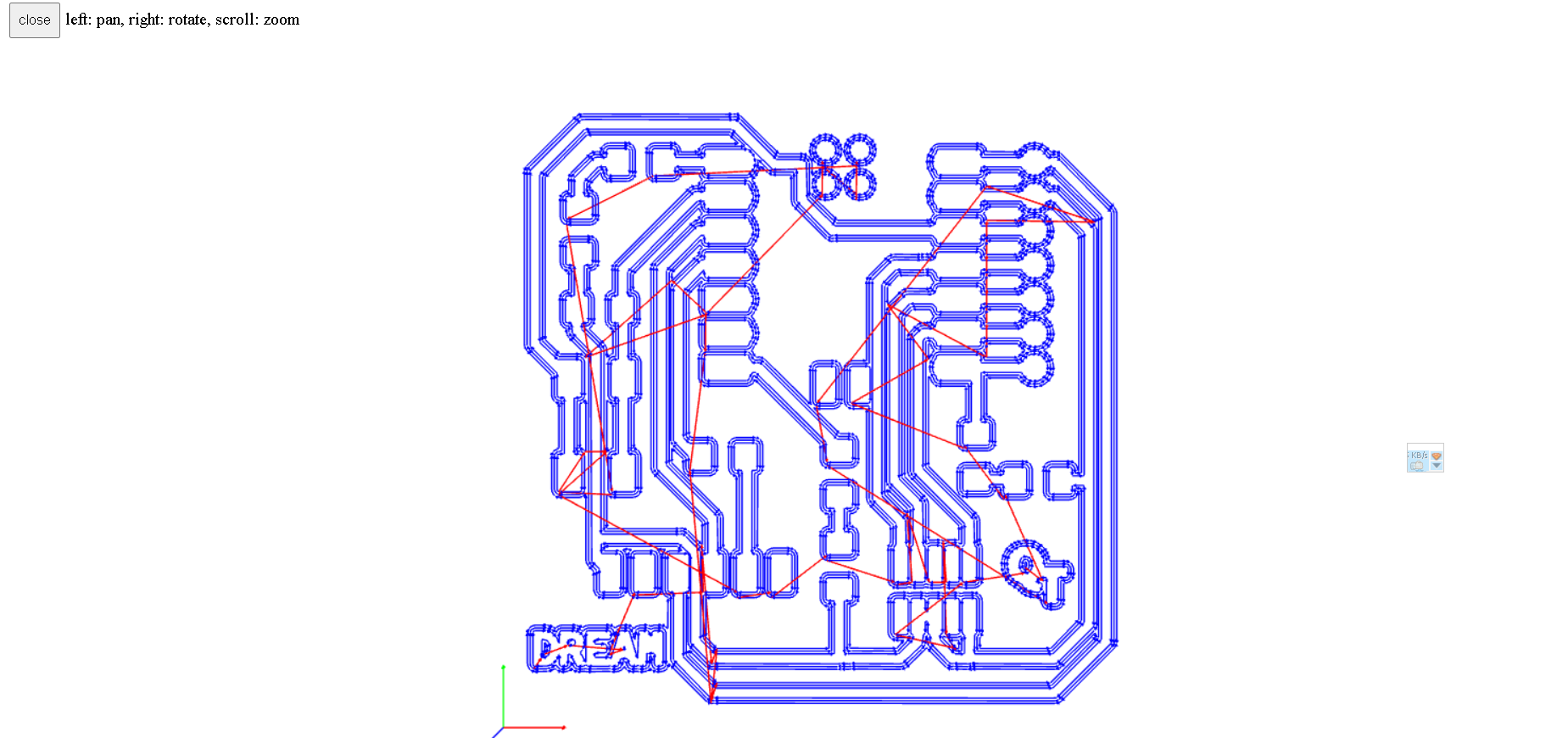
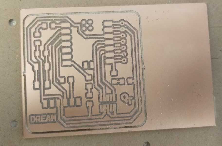
The first step was to download the three pictures of the printed circuit board (Quentorres)․ I made a very small change by adding the word dream, which excites me.
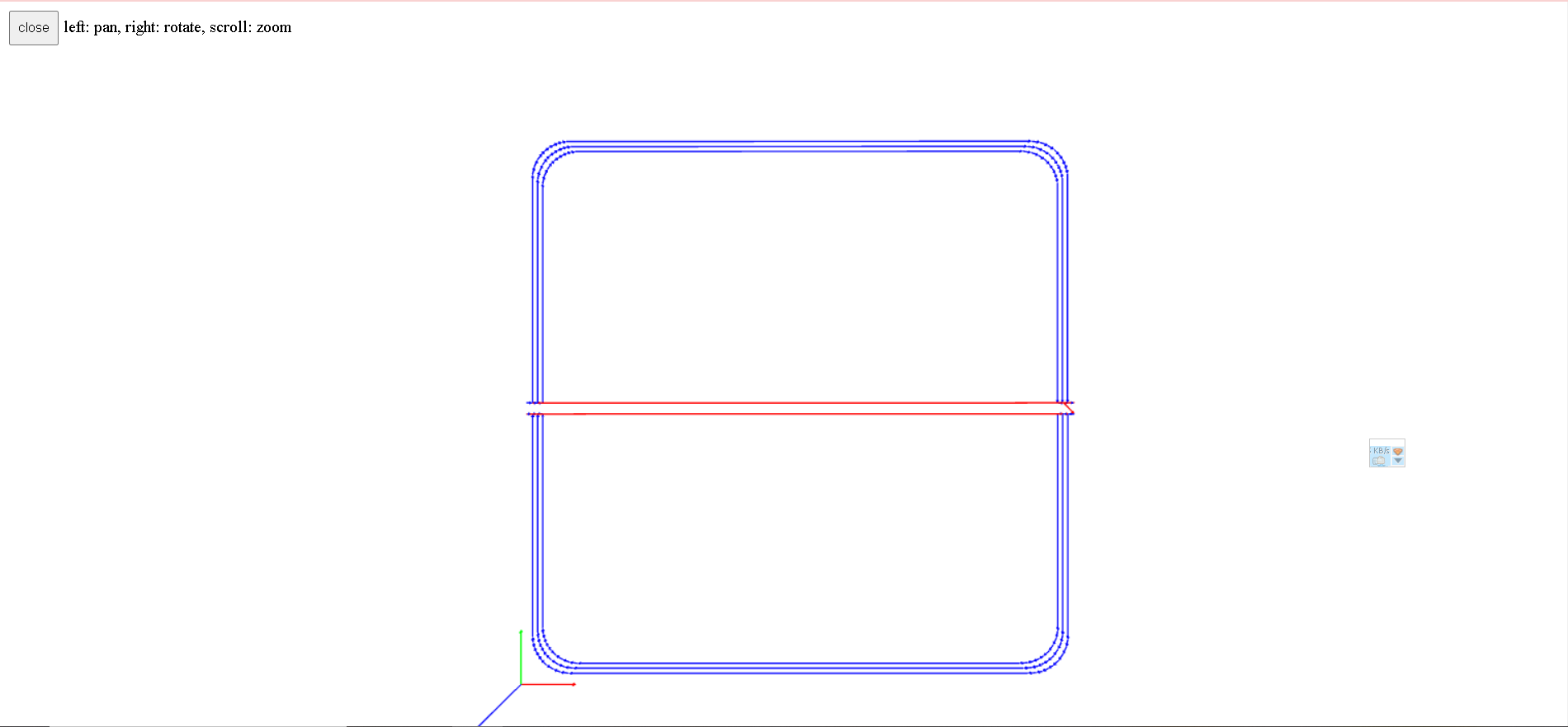
Gcode generation
Designing a PCB requires three Gcode files (drills,traces,interrior)․ I generated gcode using modsproject website․
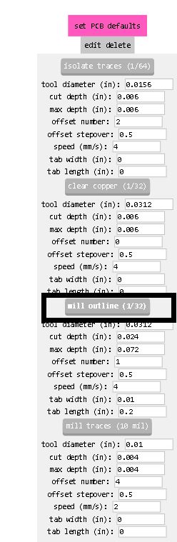
Here are the steps for trace.

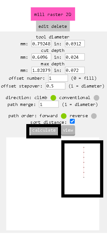
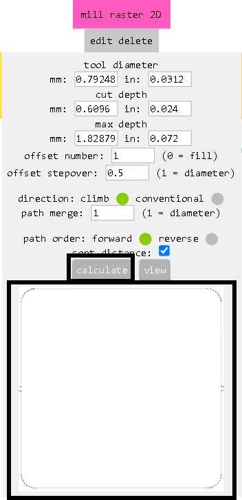
Here are the steps for drills and interior. The first 4 steps are the same as for trace.
After that I started PCB milling process. It is used in the fabrication of (PCBs) printed circuit boards . It involves the use of a milling machine to remove unwanted copper from a copper-c lad substrate to create the desired circuit pattern. This process is typically used when producing low-volume or prototype PCBs, as it offers flexibility and precision in creating complex circuit designs. Milling allows you to create fine traces, isolate different circuit elements, and drill the holes for through-hole components. It’s a key step in the PCB manufacturing process, offering a cost-effective solution for small-scale production or rapid prototyping. At Dilijan FabLab, we use the Roland SRM-20 milling machine. We utilize various thicknesses of end mills, such as 1/64 and 1/32, for tasks like isolating traces, drilling holes, and cutting out the PCB.
Milling process
Here are the steps involved in the milling process:
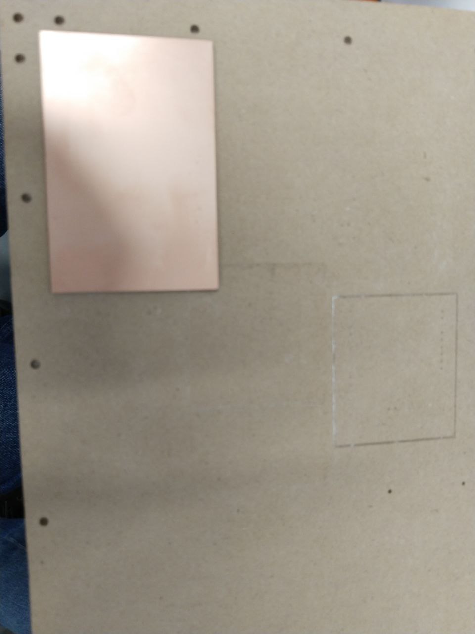
I used FR-1 copper for my PCB .
First, I use strong two sided tape to stick the copper onto the milling machine’s bed. I put tape under the entire board and pressed it down using clamps.
After that, I repositioned it in the machine and adjusted the screws to ensure its stability.
Next, I carefully insert the cutting bit into the spindle chuck and tightened securely to prevent any movement during operation.
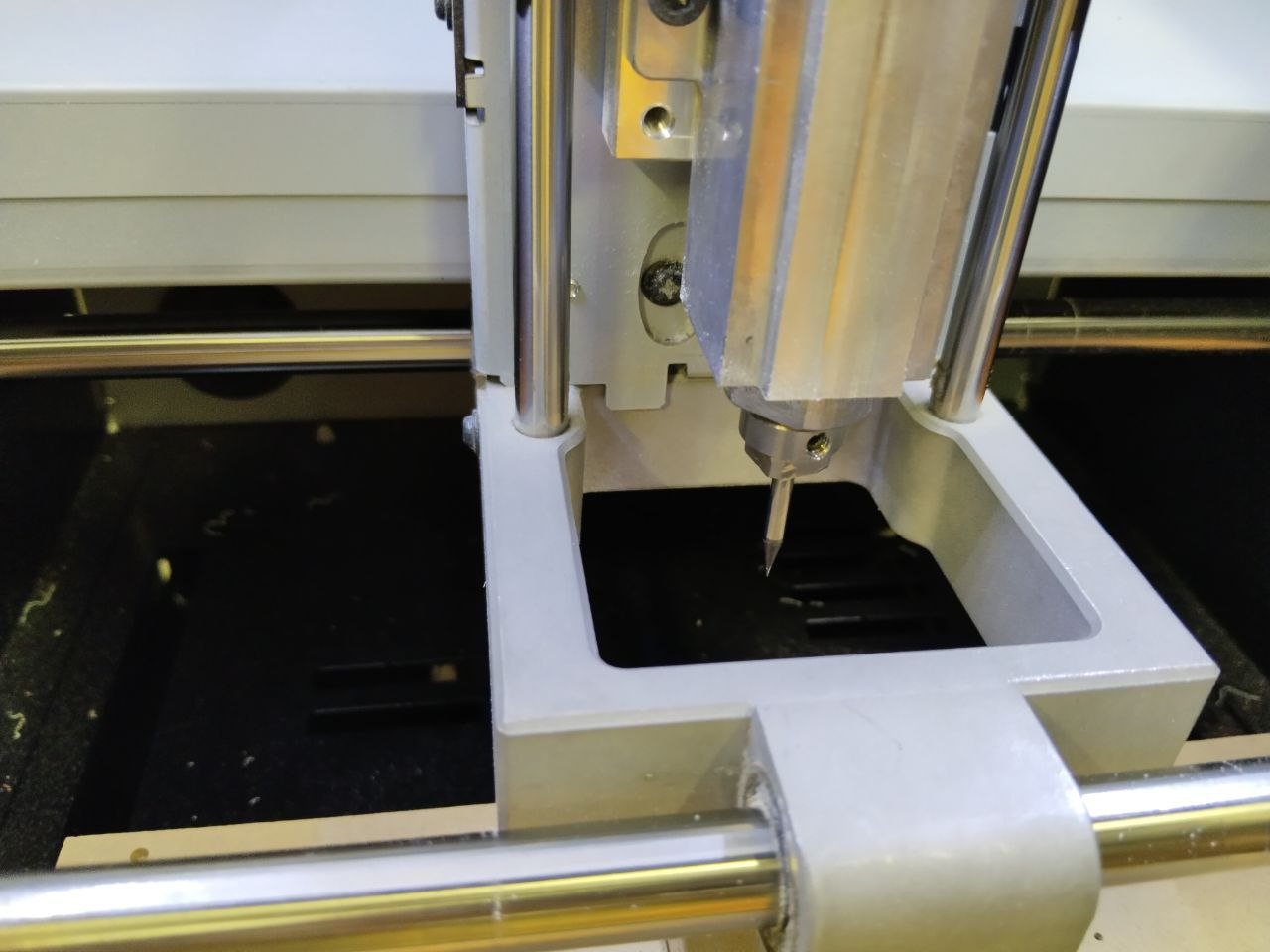
I used the SRM-20’s VPanel controller software that provides a simple interface for adjusting tool position and moving the cursor to set the milling starting point. The VPanel also allows easy control of feed rate and spindle speed with pause and resume operation, plus tracking of X,Y,Z axis milling with a numeric readout in millimeters or inches.
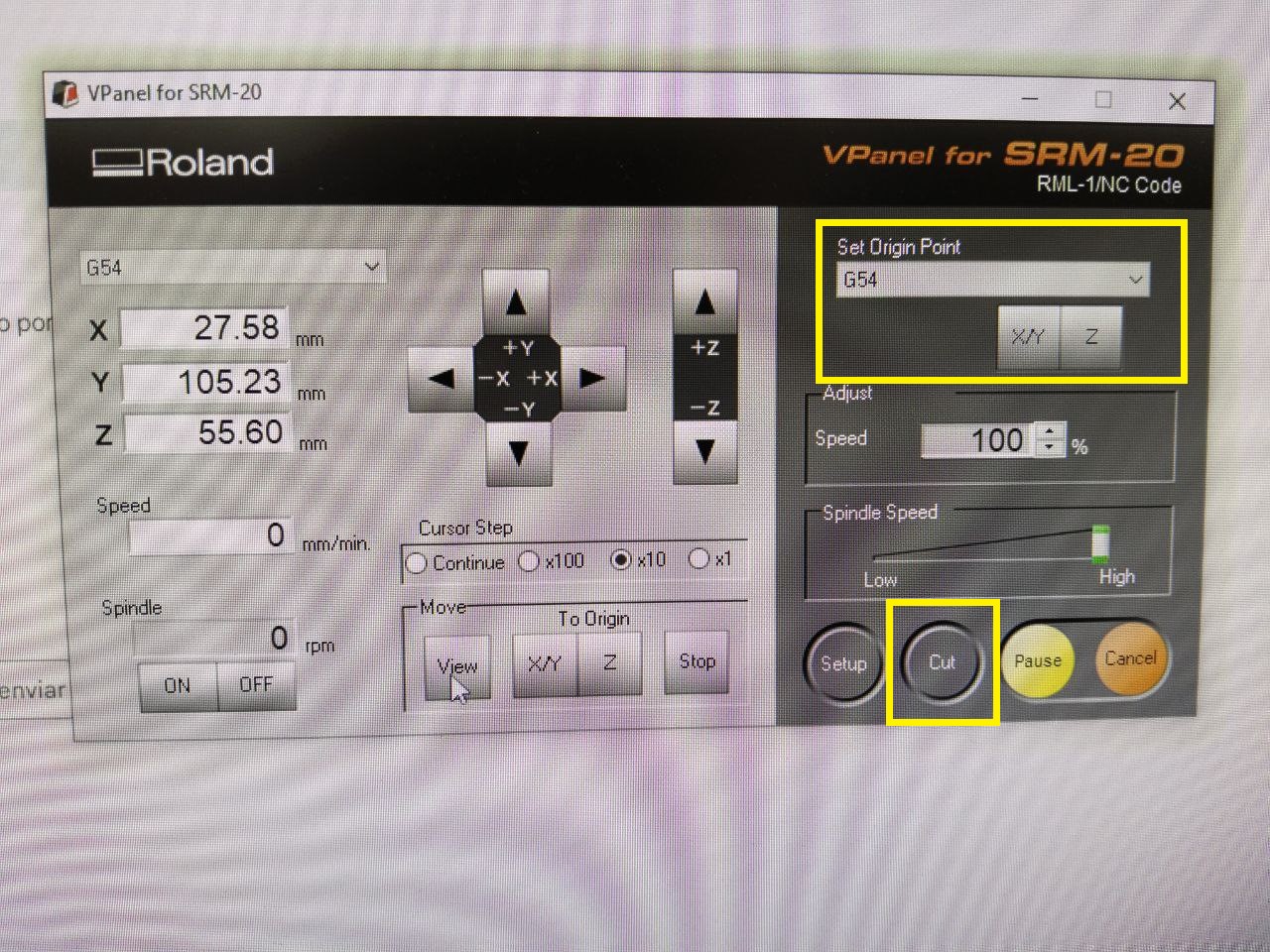
I need to set the origin points for the machine.
Setting the initial X and Y coordinates was easy, but adjusting the Z-axis was more challenging as there was a risk of damaging the milling end drill. I lowered the machine’s cutting tool, it almost touched the material. Then, I untighted the mill and let it touch the surface. Once it touched, I tightened the cutting bit .This position becomes the starting point for the Z axis.
After that I Set origin points for X/Y and Z axis from VPanel.
Another way to set the Z axis using a multimeter to adjust it. For that we need to connect the probes. I connected the multimeter probes to the cutting bit and the material surface. The cutting bit should be electrically conductive, allowing the multimeter to establish a connection. That provides a precise method for setting the cutting depth on my milling machine, ensuring accurate and consistent results.

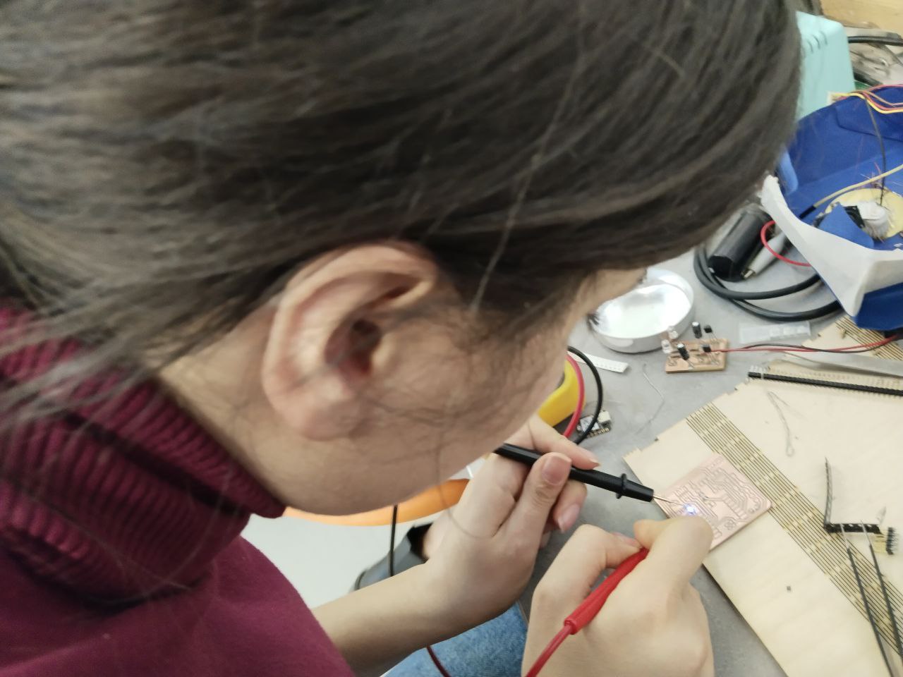
After milling PCB I needed to find components for PCB. I did it with Elen. Because we hadn’t done it before, we started training on old circuits and just then we started soldering( it need to be shiny) our PCBs and after that I checked it with multimeter to understand if I had shorts in circuit.
At first I was afraid to put iron tip on my board because of damaging risk, but Maxime encouraged me and showed me the right way to do it.
 In this PCB I used Xiao RP2040 microcontroller.
It supports multiple languages including C / MicroPython / CircuitPython.
In this PCB I used Xiao RP2040 microcontroller.
It supports multiple languages including C / MicroPython / CircuitPython.

PCB testing
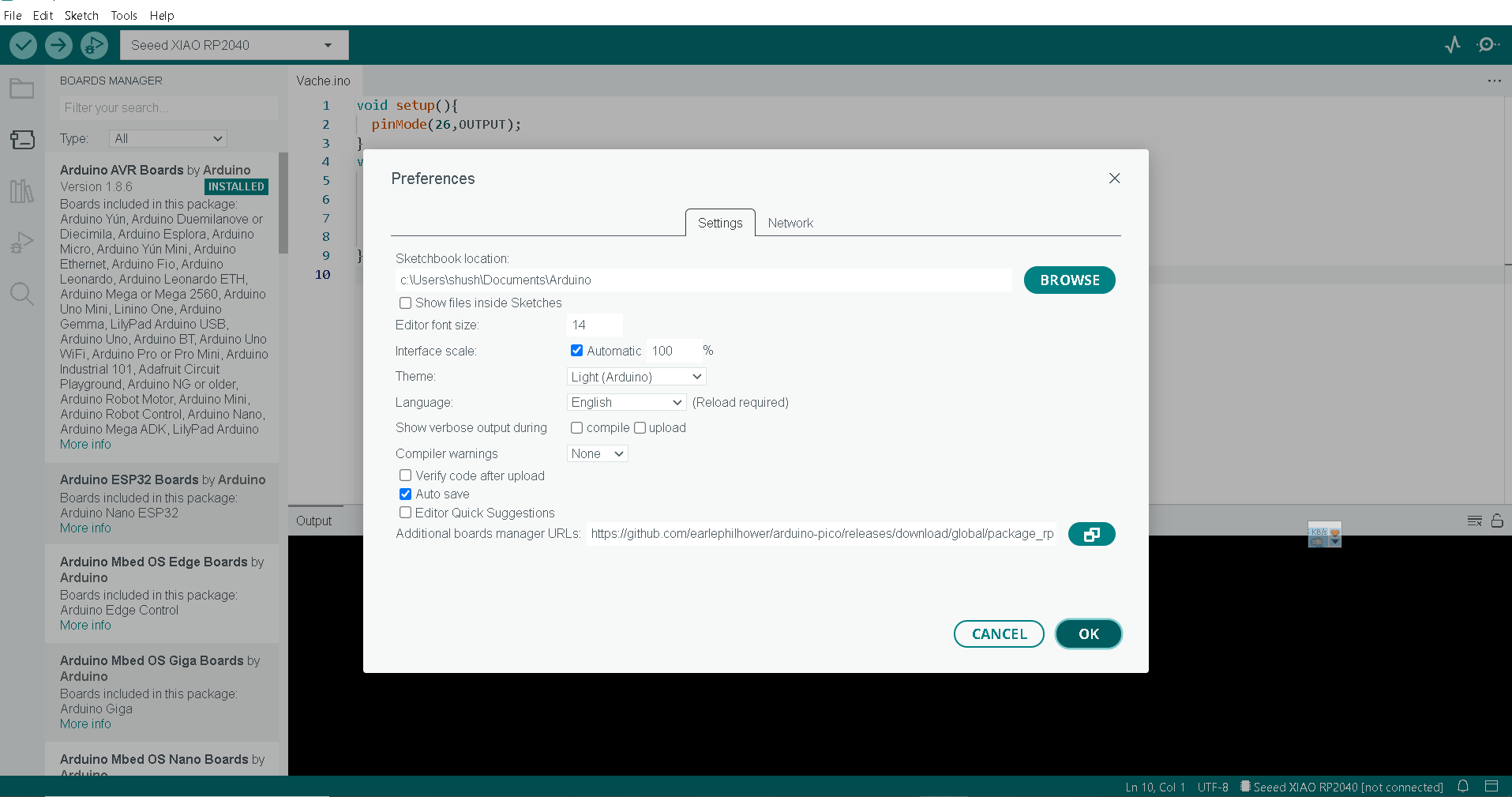
After PCB design I tested it. For that I used Arduino IDE, here are the steps.
- I Added Seeed Studio XIAO RP2040 board package to my Arduino IDE
File -> Preferences->Additional board manager URLs-> https://github.com/earlephilhower/arduino-pico/releases/download/global/package_rp2040_index.json
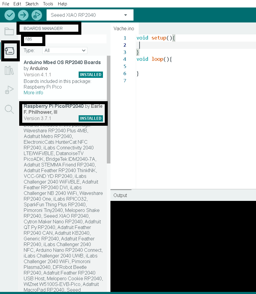
- Board Manager -> Raspberry Pi Pico->Install
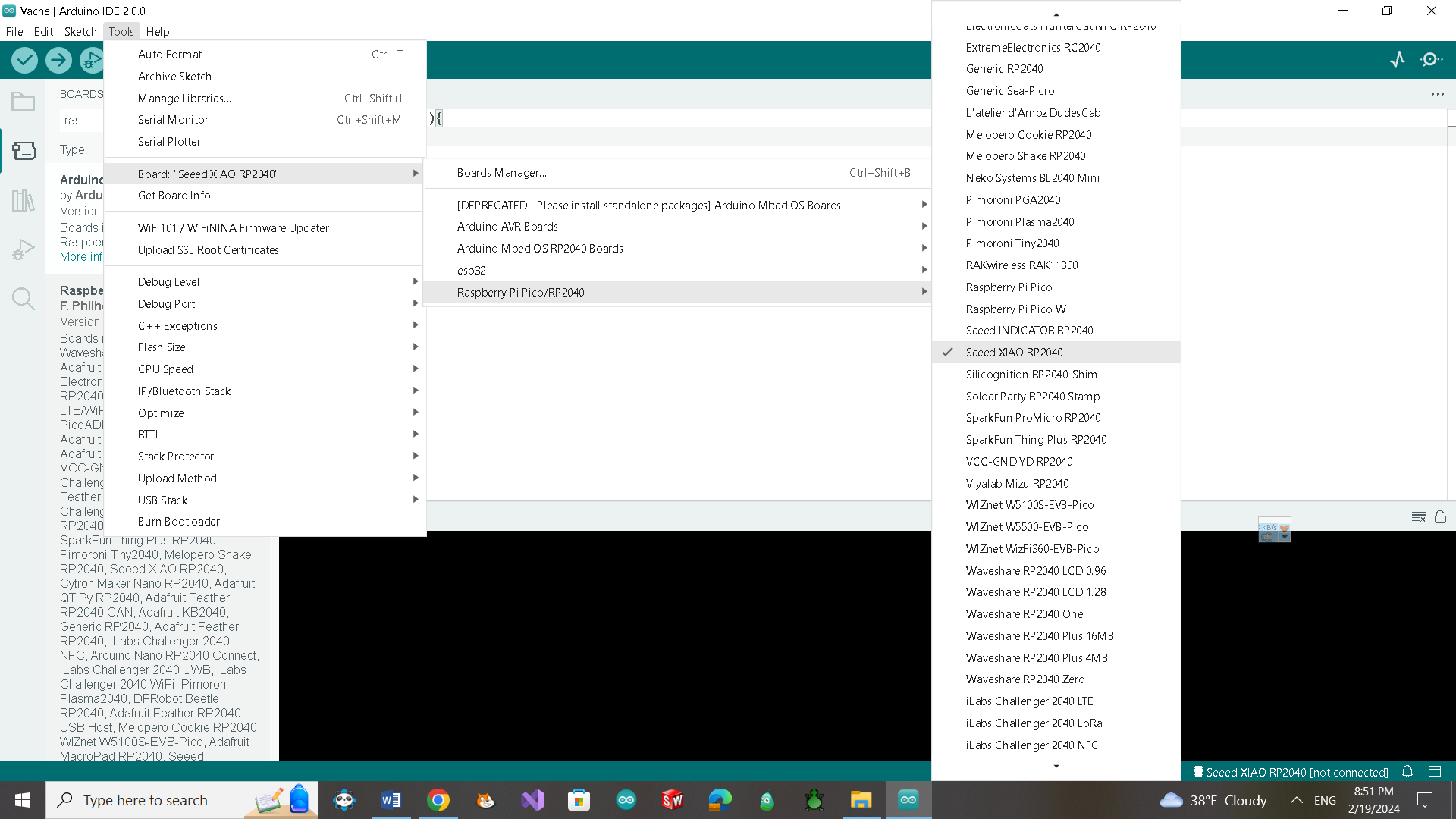
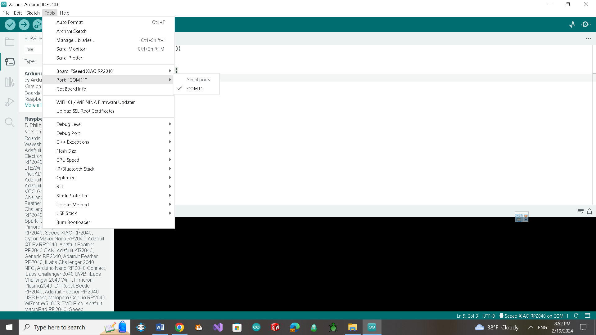
- I selected my board and port.
 I tried to upload Blink code but it failed.
I held “BOOT” button and then clicked the “RUN” button. Seeed Studio XIAO RP2040 entered boot mode. But i couldn’t upload the Arduino program again.
The solution was holding Reset and Boot buttons at the same time. This opened the mass storage.
I downloaded “blink.ino.elf.uf2” file from this link blink file
and dragged it into the mass storage.
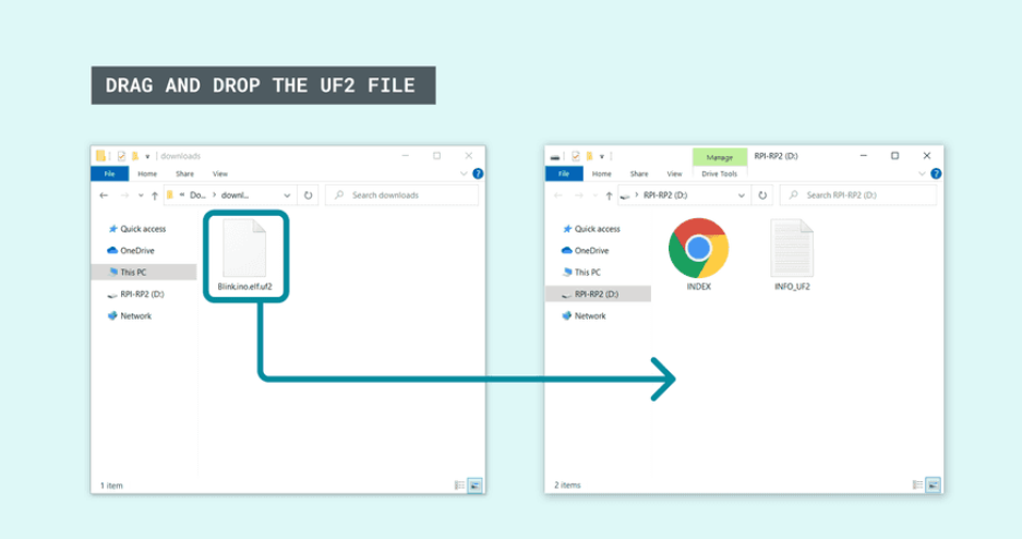 After that I could finally upload program to my board.
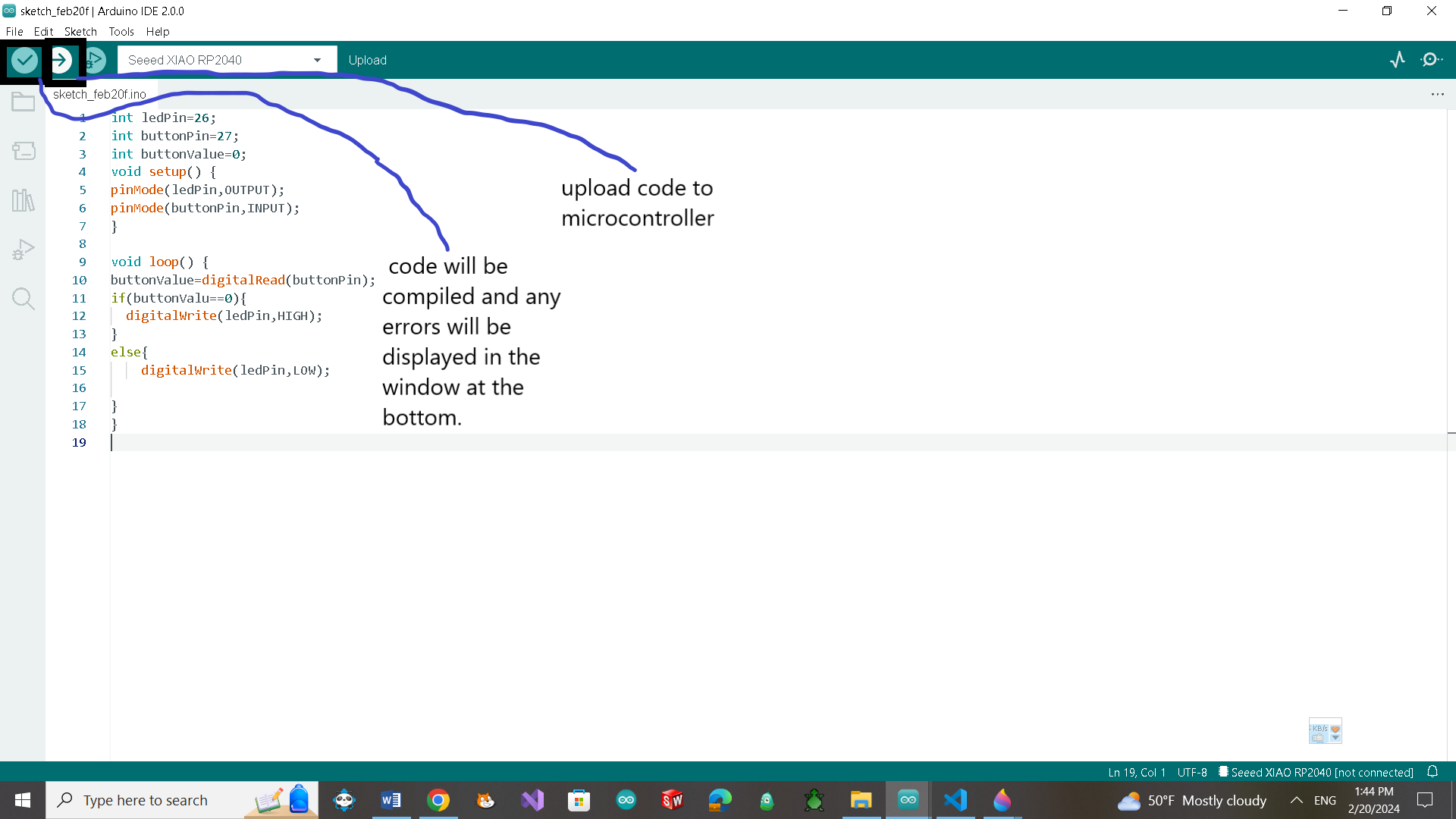
Here are codes that I tested. Led Control with button
int ledPin=26;
int buttonPin=27;
int buttonValue=0;
void setup() {
pinMode(ledPin,OUTPUT);
pinMode(buttonPin,INPUT);
}

void loop() {
buttonValue=digitalRead(buttonPin);
if(buttonValue==0){
  digitalWrite(ledPin,HIGH);
}
else{
    digitalWrite(ledPin,LOW);

}
}
Led brightness control with button
// Define the pin numbers for the LED and button
const int ledPin = 26;
const int buttonPin = 27;
// Variable to store the current state of the button
int buttonState = 0;
// Variable to store the previous state of the button
int lastButtonState = 0;
// Variable to store the brightness of the LED
int brightness = 0;
// Variable to store the step size for brightness change
int fadeAmount = 5;
void setup() {
  // Initialize the LED pin as an output
  pinMode(ledPin, OUTPUT);
  // Initialize the button pin as an input
  pinMode(buttonPin, INPUT);
}

void loop() {
  // Read the state of the button
  buttonState = digitalRead(buttonPin);
  // Check if the button is pressed
  if (buttonState != lastButtonState) {
    // Increment the brightness if the button is pressed
    if (buttonState == HIGH) {
      brightness = brightness + fadeAmount;
      // Ensure brightness stays within bounds (0 to 255)
      brightness = constrain(brightness, 0, 255);
    }
  }
  // Update the LED brightness
  analogWrite(ledPin, brightness);
  // Update the last button state
  lastButtonState = buttonState;
}
Button to Toggle an LED
// Define the pin numbers for the LED and button
const int ledPin = 26;
const int buttonPin = 27;
int buttonState = 0;
int lastButtonState = 0;
void setup() {
  // Initialize the LED pin as an output
  pinMode(ledPin, OUTPUT);
  // Initialize the button pin as an input
  pinMode(buttonPin, INPUT);
}
void loop() {
  // Read the current state of the button
  buttonState = digitalRead(buttonPin);
  // Check if the button state has changed
  if (buttonState != lastButtonState) {
    // If the button is pressed
    if (buttonState == LOW) {
      // Toggle the LED state
      digitalWrite(ledPin, !digitalRead(ledPin));
    }
    // Save the current button state for the next loop iteration
    lastButtonState = buttonState;
  }
}
Group assigment
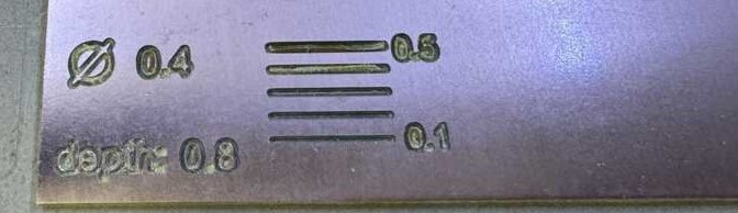
For our group assignment, we conducted tests on a V-bit mill. Our goal was to determine its diameters at various depths and to understand how to configure the parameters for different thicknesses. To begin, we designed a simple test pattern in Inkscape. We then prepared the mill and initiated the engraving process on these lines. We assumed a fictitious tool diameter of 0.4 because we were unsure of its actual diameter at each depth. Starting with a depth of 0.8, we proceeded to engrave several lines with thicknesses ranging from 0.1 to 0.5 mm.
We opted to create a single line that would progressively deepen over a set distance, allowing us to measure it accurately. To achieve this, we needed the mill to spin and follow a single axis while incrementally increasing the depth. This led to an intriguing experiment facilitated by Ashot’s skill in manually generating a g-code.
%
G17
G21
G40
G49
G54
G80
G90
G94
S11000
G00Z2.0000
M03
G00Z2.0000
G00X0.0000Y0.0000Z2.0000
G01 Z0 F100
G01 X40 Z-1.6
Z50
M05
M30
%
G-code explanation.
- G17: This command specifies that the XY plane is the active plane for machining. It means that movements and coordinates will be interpreted in the XY plane.
- G21: This command sets the units to millimeters. It indicates that subsequent coordinates and distances are in millimeters.
- G40: This command cancels the cutter radius compensation. It ensures that the tool follows the exact path specified without any additional offset due to the tool’s radius.
- G49: This command cancels any tool length compensation. It ensures that the tool’s length is not adjusted during machining.
- G54: This command selects the coordinate system (work offset) G54. Different coordinate systems can be used for different workpieces or setups.
- G80: This command cancels any canned cycle (such as drilling or tapping cycles).
- G90: This command sets the machine to operate in absolute mode. All subsequent coordinates are interpreted as absolute positions from the origin.
- G94: This command sets the feed rate mode to units per minute (G93 would set it to units per revolution).
- S11000: This sets the spindle speed to 11,000 RPM (revolutions per minute).
- G00 Z2.0000: Rapid move to Z-coordinate 2.0000 (moves the tool quickly to a safe height).
- M03: This command starts the spindle (clockwise rotation).
- G00 Z2.0000: Another rapid move to Z-coordinate 2.0000 (still at a safe height).
- G00 X0.0000 Y0.0000 Z2.0000: Rapid move to the XY origin (X=0, Y=0) at Z-coordinate 2.0000.
- G01 Z0 F100: Linear move (feed rate of 100 mm/min) to Z-coordinate 0 (lowering the tool).
- G01 X40 Z-1.6: Linear move to X-coordinate 40 and Z-coordinate -1.6 (machining a specific path).
- Z50: This appears to be a standalone Z-coordinate move to 50 (without specifying an X or Y coordinate).
- M05: This command stops the spindle (turns it off).
- M30: This is the program end command.
In summary, this G-code snippet sets up the machine, specifies the spindle speed, moves the tool to various positions, and ends the program.
We were drawing mill’s shape with sizes and tried to solve it mathematically.
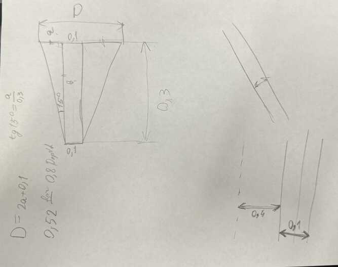
Since we lacked knowledge about the tip diameter of the V-bit mill, we assumed it to be 0.2. Areg derived a formula to calculate the necessary parameters for our experiment.
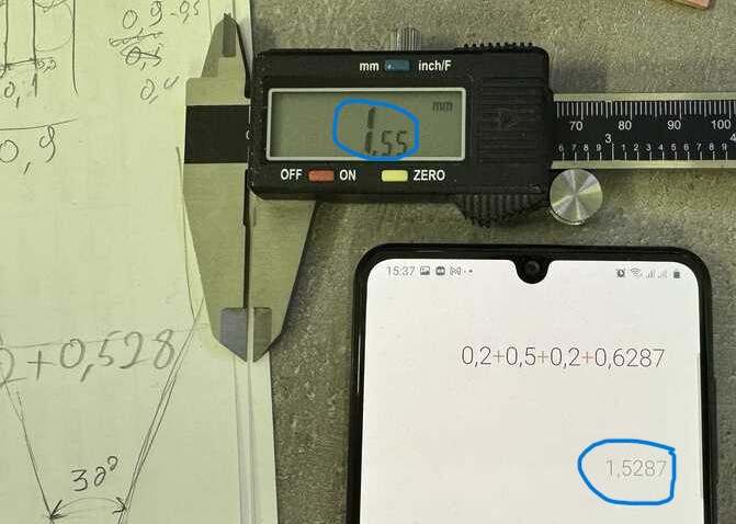
Since we were uncertain about the tip diameter, we initially set it to 0.1. However, it’s worth noting that we also have the option to adjust other parameters if we assume a tip diameter of 0.2. Consequently, we couldn’t achieve perfect results due to potential inaccuracies stemming from parameters like the tip diameter and machine vibrations. Nevertheless, theoretically, for a 30-degree angled mill, we devised a method to determine the depth and thickness using this parametric drawing in SolidWorks.
Conclusion
This week has been really interesting for me because I tried making a PCB for the first time. It’s amazing that I can create my own custom board. Honestly, soldering seemed quite complicated at first, but with the help of the instructors’ advice, it became incredibly easy. Their guidance made a big difference, breaking down the steps and making everything clear.Also I learned about different types of endmills their application, I got aquatinted to the Gcode and how to generate it. Moreover I learned how to manually edit the Gcode. Overall, this experience has been eye-opening, and I’m excited to continue learning and improving in electronics fabrication.