12. Input devices
This week’s assignment was to measure something: add a sensor to a microcontroller board that I have designed and read it.
Group assigment
This week group assigment was probe an input device(s)’s analog levels and digital signals. We tested Sharp GP2Y0A21YK0F(analog sensor) and HC-SR04 Ultrasonic Sensor(digital sensor).
HC-SR04 Ultrasonic Sensor
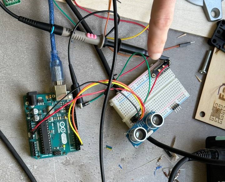 We wrote code with NewPing.h library and without it for HC-SR04 Ultrasonic Sensor.
What was interesting for me was that this sensor doesn’t work with fabric materials.
Then we found out that the sensor needed a pretty solid object to bounce sound for these walls are good but cloth absorbs the sound wave and the echo never bounces back.
Here are the codes we used.
We wrote code with NewPing.h library and without it for HC-SR04 Ultrasonic Sensor.
What was interesting for me was that this sensor doesn’t work with fabric materials.
Then we found out that the sensor needed a pretty solid object to bounce sound for these walls are good but cloth absorbs the sound wave and the echo never bounces back.
Here are the codes we used.
First without library.
const int trigPin = 9;
const int echoPin = 10;

float duration, distance;

void setup() {
  pinMode(trigPin, OUTPUT);
  pinMode(echoPin, INPUT);
  Serial.begin(9600);
}

void loop() {
  digitalWrite(trigPin, LOW);
  delayMicroseconds(2);
  digitalWrite(trigPin, HIGH);
  delayMicroseconds(10);
  digitalWrite(trigPin, LOW);

  duration = pulseIn(echoPin, HIGH);
  distance = (duration*.0343)/2;
  Serial.print("Distance: ");
  Serial.println(distance);
  delay(100);
}
With NewPing.h library.
#include <NewPing.h>
#define TRIGGER_PIN 12 // Arduino pin connected to the sensor's trigger pin
#define ECHO_PIN 11    // Arduino pin connected to the sensor's echo pin
#define MAX_DISTANCE 200 // Maximum distance to measure (in centimeters)

NewPing sonar(TRIGGER_PIN, ECHO_PIN, MAX_DISTANCE);

void setup() {
    Serial.begin(9600);
}

void loop() {
    delay(50); // Wait for sensor stability
    unsigned int distance = sonar.ping_cm();
    Serial.print("Distance: ");
    Serial.print(distance);
    Serial.println(" cm");
}
We also tested the sensor with the oscilloscope.
Here is the result.

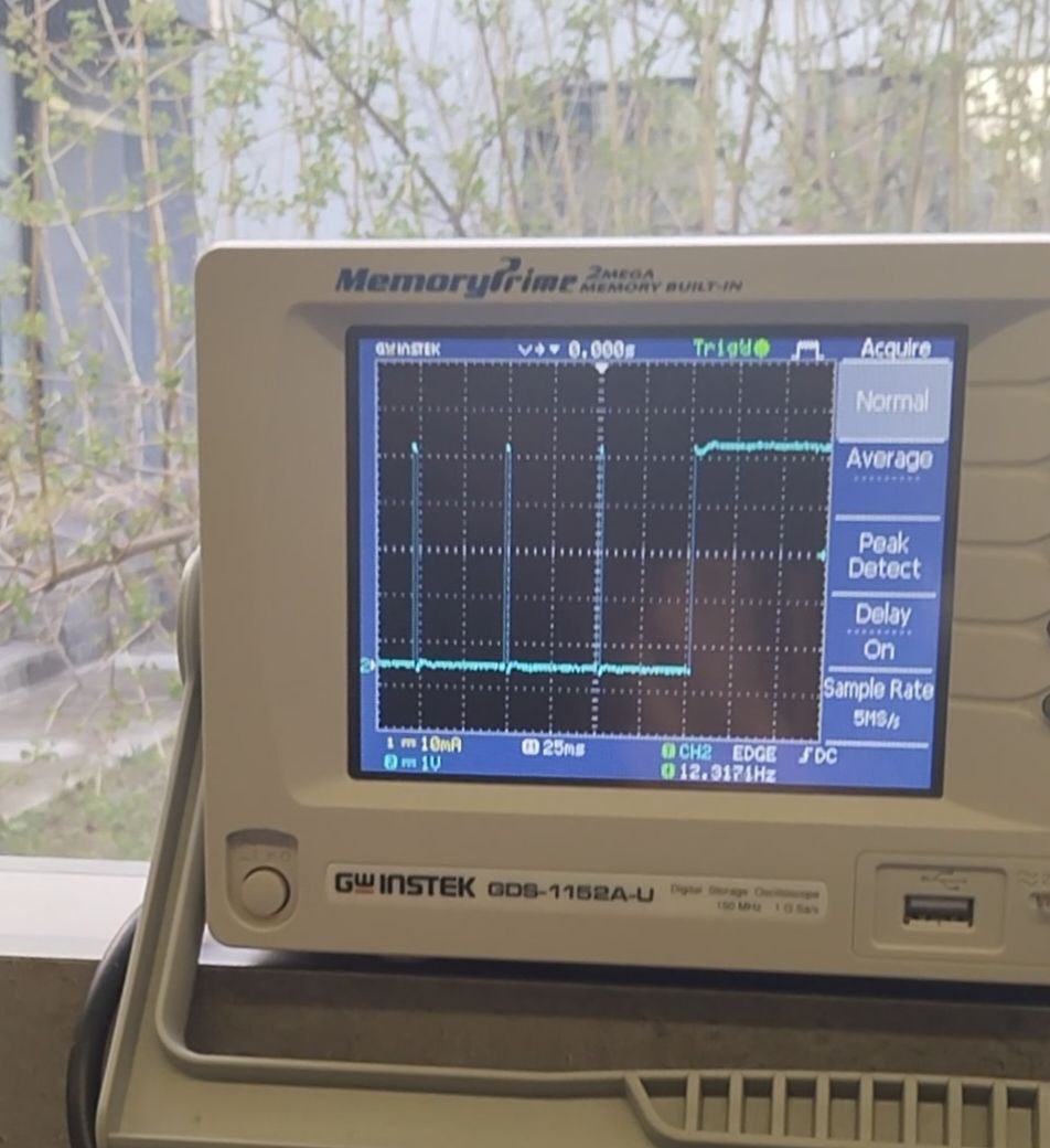 When the distance between the sensor and the detected object is smaller waves in the oscilloscope become smaller.
The Sharp GP2Y0A21YK0F IR sensor
After that, we used a Sharp GP2Y0A21YK0F sensor. The Sharp GP2Y0A21YK0F is an infrared (IR) distance sensor that uses infrared light to measure distances. The sensor emits an infrared beam toward an object. When the beam reflects off the object, it reaches a light detector (Position Sensing Device or PSD). The position of the reflected beam on the PSD changes as the object’s position changes. The sensor’s built-in signal processing circuit calculates the distance based on the position of the optical spot on the PSD. It outputs an analog signal that corresponds to the object’s distance in front of the sensor. First, we wired the sensor wrote the code that was given as the sensor, and started manually measuring it.
#define IR_SENSOR_PIN A0

void setup() {
    Serial.begin(9600);
}

void loop() {
    int sensorValue = analogRead(IR_SENSOR_PIN);
    Serial.println(sensorValue);
}
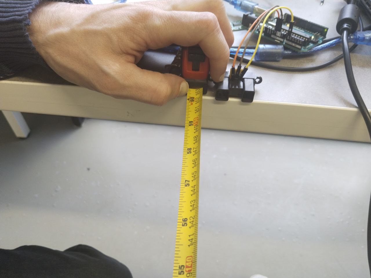
After that, we wrote the results in Excel and made a table that had two columns analog values and distance that we measured and made the chart with Excel.

The relationship between the sensor’s analog output voltage and the distance is often nonlinear as we can see in our example. In the case of the GP2Y0A21YK0F, this relationship is approximated by an exponential function.

In the code, we forgot a minus sign but we corrected it and it worked. In our case function was 145712x^-1.05 We wrote code using our results.
int irsensor=A0;
int sensorValue;
void setup(){
  pinMode(irSenor,INPUT);
  Serial.begin(9600);
}
void loop(){
  sensorValue=analogRead(irSensor);
  float distance= 145712*pow(sensorValue,-1.05);
  Serial.println(sensorValue);
  delay(500);
}
It worked but was not very accurate. Maybe because of ambient light, and noise or we needed to do more measurements.
After that, we wrote the code that worked more accurately from this webpage.
const int sensorPin = A0;
const long referenceMv = 5000;

void setup() {
  Serial.begin(9600);
  pinMode(ledPin, OUTPUT);
}

void loop() {
  //reading the voltage
  int val = analogRead(sensorPin);
  int mV = (val * referenceMv) / 1023;
  int cm = getDistance(mV);


  //display values on the screen
  Serial.print(mV);
  Serial.print(",");
  Serial.println(cm);

  delay(1000);
}

//interpolation of distance at 250mV intervals
const int TABLE_ENTRIES = 12;
const int INTERVAL  = 250;
static int distance[TABLE_ENTRIES] = {150,140,130,100,60,50,40,35,30,25,20,15};

int getDistance(int mV) {
  if (mV > INTERVAL * TABLE_ENTRIES - 1)      return distance[TABLE_ENTRIES - 1];
  else {
    int index = mV / INTERVAL;
    float frac = (mV % 250) / (float)INTERVAL;
    return distance[index] - ((distance[index] - distance[index + 1]) * frac);
  }
}

Individual assigment
Research for filament runout sensor
This week I decided to use the input device that I needed in my final project the filament runout sensor. I did research and found some ways that I could make it.
The common way that I found was with the end switch. I wanted to test a sensor that worked with capacitive touch. Maxime sent me useful links to understand how it works.
Step Response board
After that, I read Adrian’s documentation and it helped me a lot.
Adrinan’s documentation
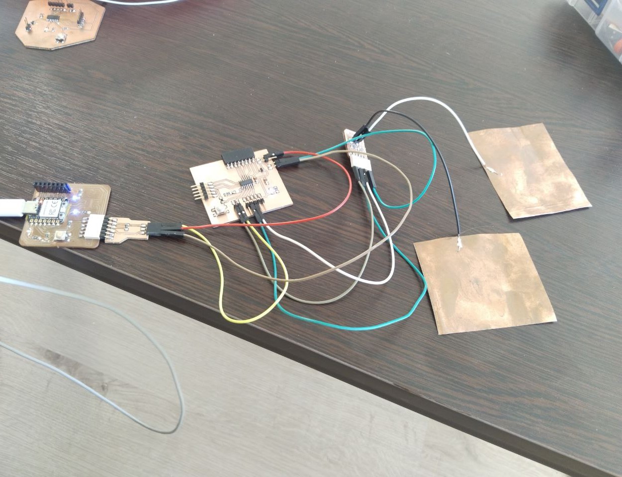
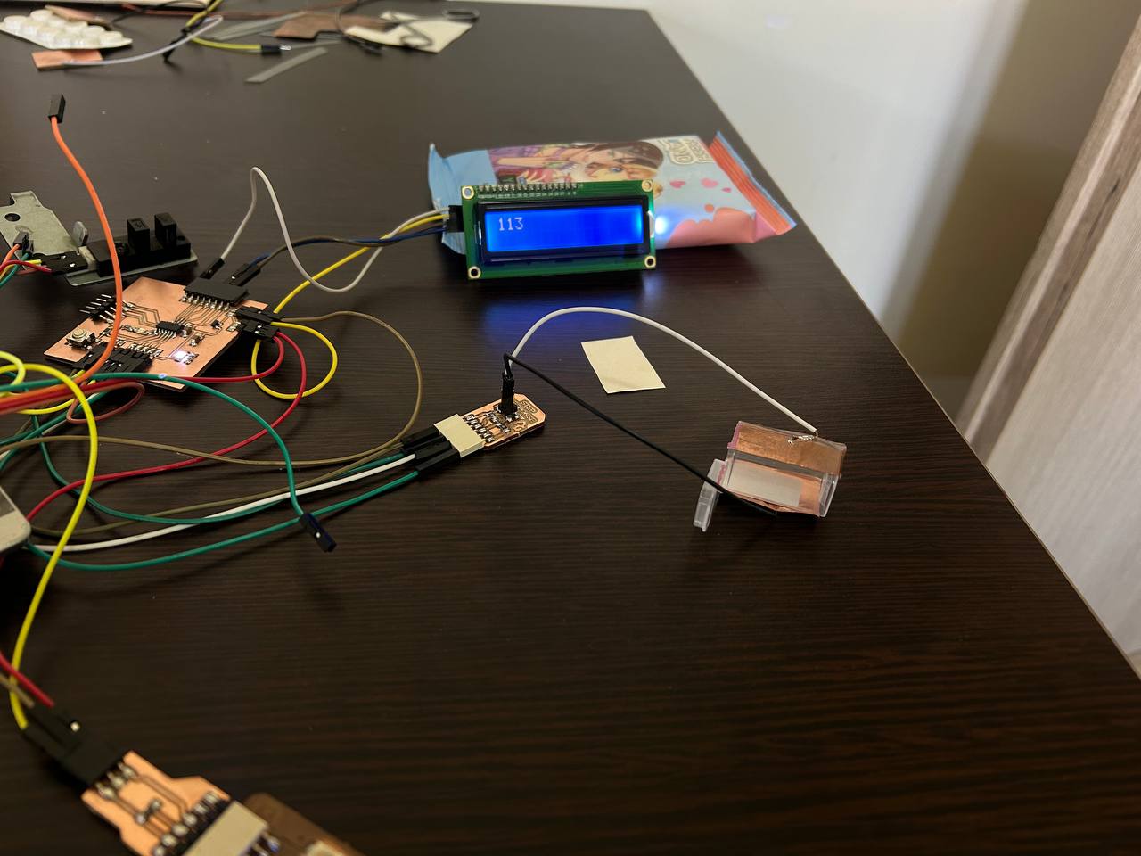
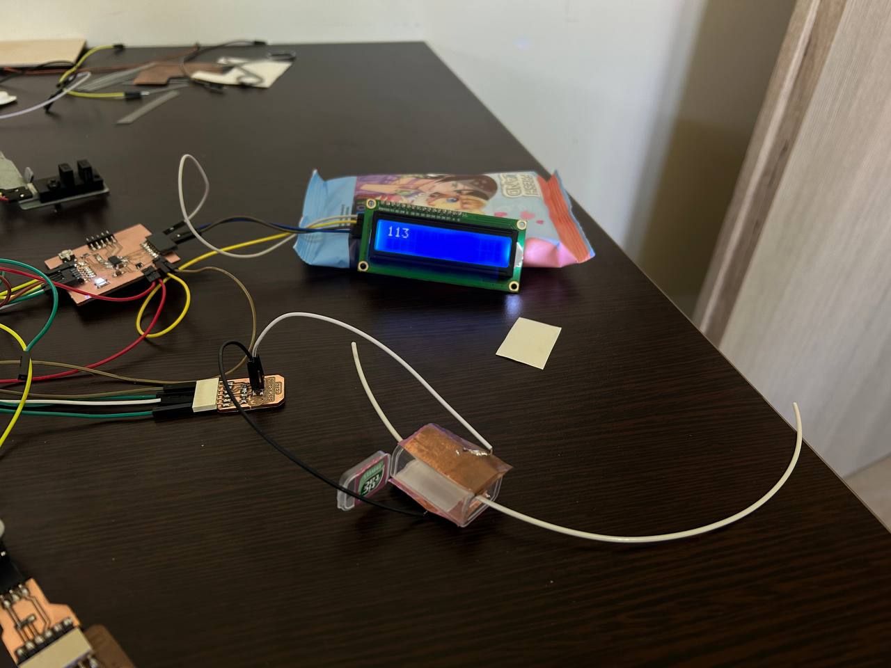
I decided for testing make Adrian’s Step Response board and tested it to understand if it would work with filament or not.
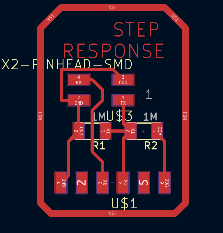

After that, I connected it with my board.
Programming
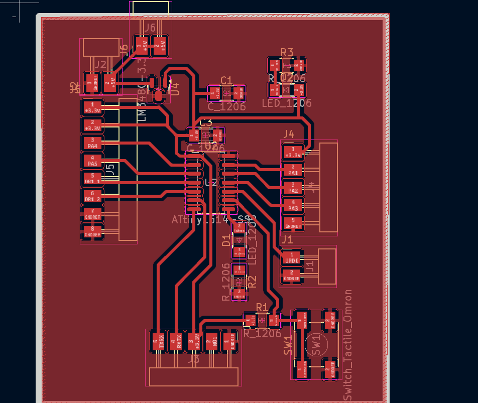
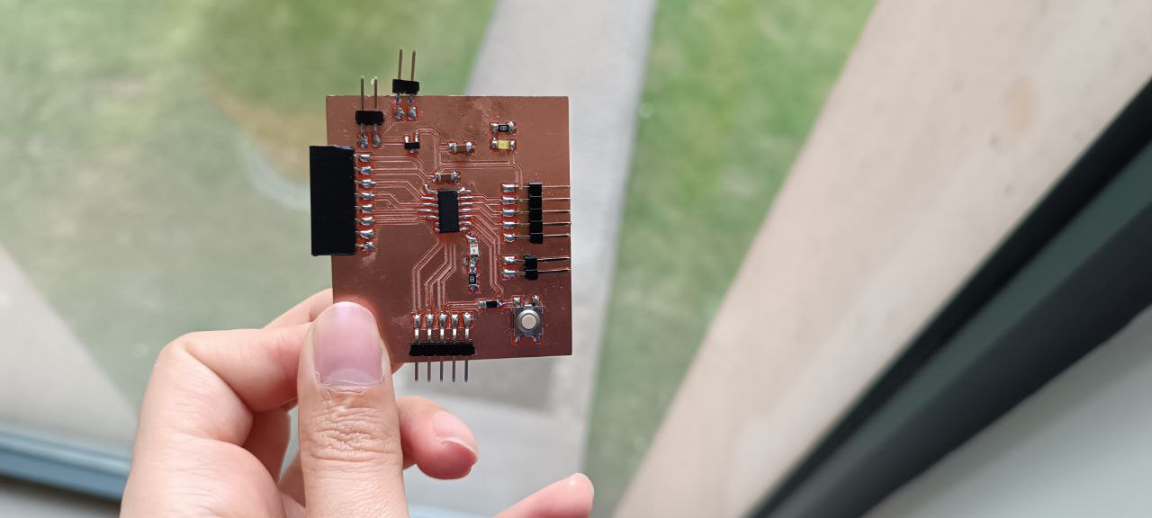
Then I wrote the code and uploaded it to the board that I made this week I modified my Output week board and added a pin for 5V output, because in Output week because of that I had to use a breadboard.
but in Serial monitor didn’t print any results.
I also tried to upload other code with CapasitiveSensor.h library but it didn’t work either because I used UPDI Serial programming.

That’s why I decided to add an LCD screen for monitoring results. In my board, I used SCL and SDA pins to connect the SMD LED and button and that helped me find the solution to how at the software level I can make other digital pins to SDA and SCL. I used SoftwareWire.h and hd44780.h libraries. I found this solution in the Arduino Forum. Arduino forum solution After that I rewrite code.
#include <SoftwareWire.h>
const int sda = 0, scl = 1;
SoftwareWire Wire(sda, scl);
#include <hd44780.h>
#include <hd44780ioClass/hd44780_I2Cexp.h>
hd44780_I2Cexp lcd; // declare lcd object and let it auto-configure everything.
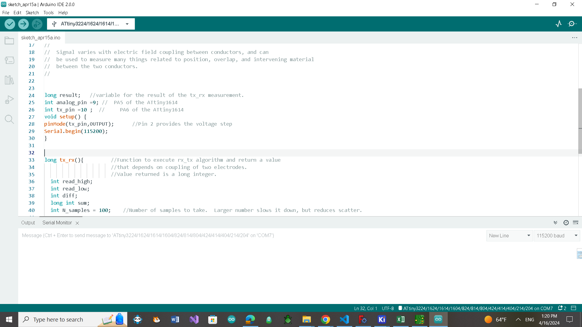
long result; //variable for the result of the tx_rx measurement.
int analog_pin = 10; // PA5 of the ATtiny1614
int tx_pin = 9;
void setup() {
int istatus;
istatus = lcd.begin(16, 2);
if (istatus) {
// LCD initalization failed.
// handle it anyway you want
if (istatus < 0)
istatus = -istatus;
lcd.fatalError(istatus); // blinks error if LED_BUILTIN is defined
}
pinMode(tx_pin, OUTPUT); //Pin 2 provides the voltage step
Serial.begin(9600);
}
long tx_rx() { //Function to execute rx_tx algorithm and return a value
//that depends on coupling of two electrodes.
//Value returned is a long integer.
int read_high;
int read_low;
int diff;
long int sum;
int N_samples = 100; //Number of samples to take. Larger number slows it down, but reduces scatter.
sum = 0;
for (int i = 0; i < N_samples; i++) {
digitalWrite(tx_pin, HIGH); //Step the voltage high on conductor 1.
read_high = analogRead(analog_pin); //Measure response of conductor 2.
delayMicroseconds(100); //Delay to reach steady state.
digitalWrite(tx_pin, LOW); //Step the voltage to zero on conductor 1.
read_low = analogRead(analog_pin); //Measure response of conductor 2.
diff = read_high - read_low; //desired answer is the difference between high and low.
sum += diff; //Sums up N_samples of these measurements.
}
return sum;
} //End of tx_rx function.
void loop() {
result = tx_rx();
result = map(result, 8000, 11000, 0, 1023); //I recommend mapping the values of the two copper plates, it will depend on their size
lcd.print(result);
delay(400);
lcd.clear();
}
Testing
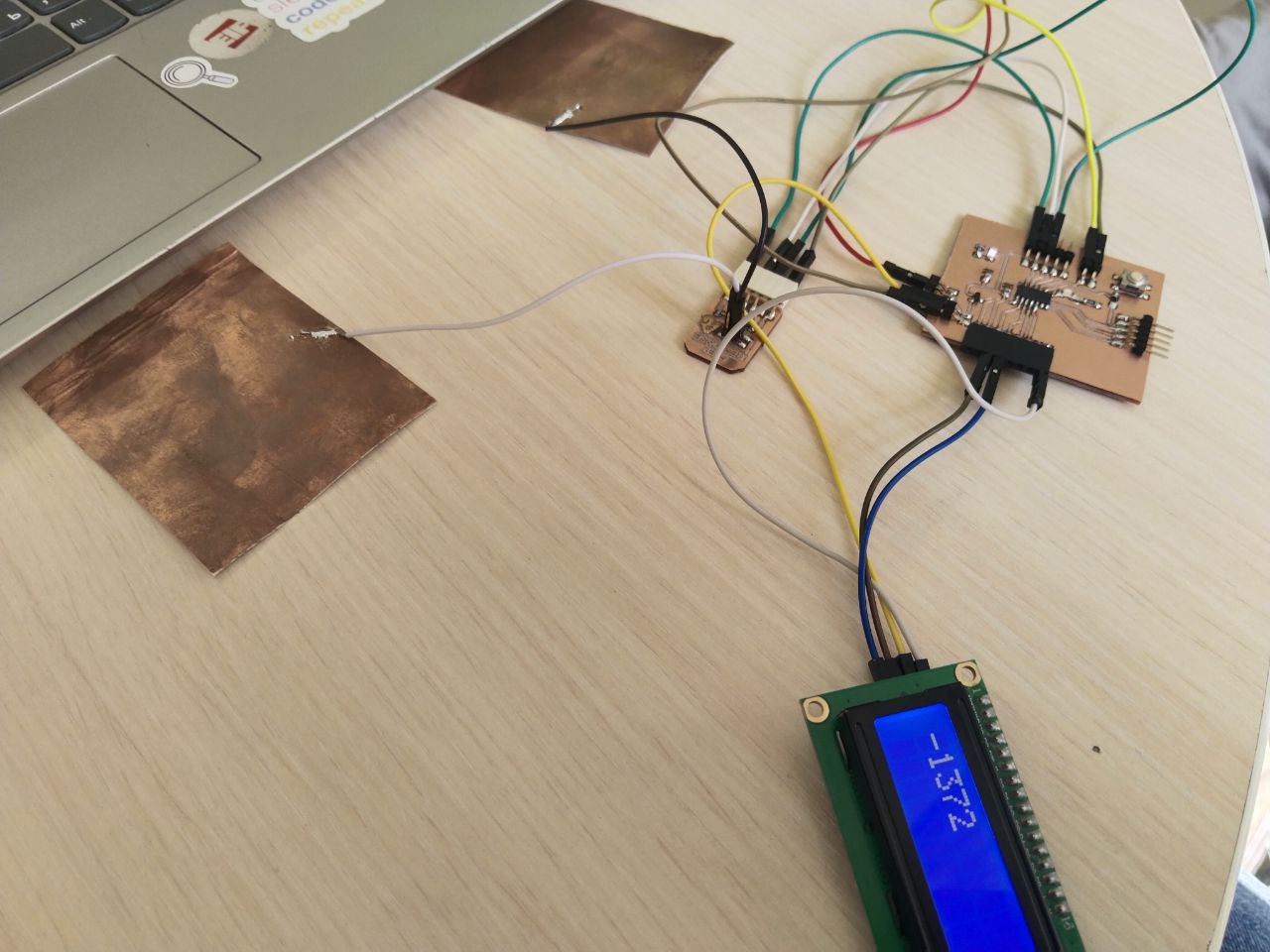
Here are the first test results.
At first, I just tried to understand how they work and didn’t consider the distance between two plates also the size of the plates.
Here is the result when the plates were far from each other and I didn’t touch them.
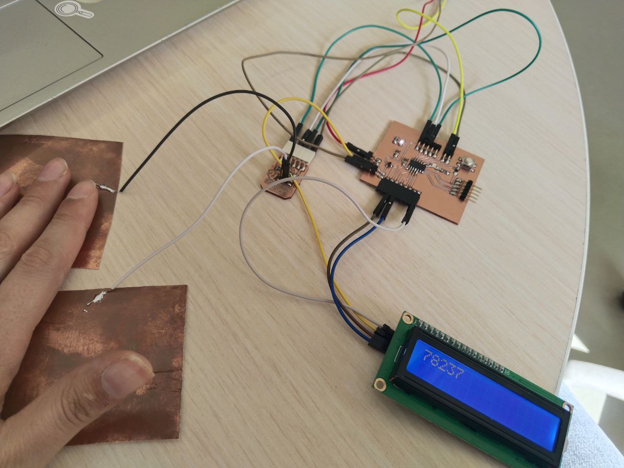
Here when I touch the plate I connect the Tx pin.

And here when I touched two plates at the same time.
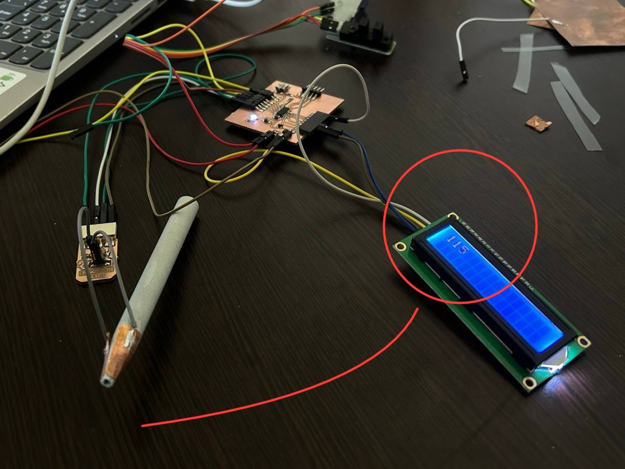
After the first test, I realized that I could change the values of the mapping for not getting the result with a minus sign. result = map(result, 3500, 8000, 0, 1023);
It helped but again the values that I got changed their range very fast.
Because the difference in result was huge I tried modifying the code a little bit.
#include <SoftwareWire.h>
const int sda = 0, scl = 1;
SoftwareWire Wire(sda, scl);
#include <hd44780.h>
#include <hd44780ioClass/hd44780_I2Cexp.h>
hd44780_I2Cexp lcd;   // declare lcd object and let it auto-configure everything.
long result;          //variable for the result of the tx_rx measurement.
int analog_pin = 10;  //  PA5 of the ATtiny1614
int tx_pin = 9;
void setup() {
  int istatus;

  istatus = lcd.begin(16, 2);
  if (istatus) {
    // LCD initalization failed.
    // handle it anyway you want
    if (istatus < 0)
      istatus = -istatus;
    lcd.fatalError(istatus);  // blinks error if LED_BUILTIN is defined
  }
  pinMode(tx_pin, OUTPUT);  //Pin 2 provides the voltage step
  Serial.begin(9600);
}
long tx_rx() {  //Function to execute rx_tx algorithm and return a value
                //that depends on coupling of two electrodes.
                //Value returned is a long integer.
  int read_high;
  int read_low;
  int diff;
    digitalWrite(tx_pin, HIGH);          //Step the voltage high on conductor 1.
    read_high = analogRead(analog_pin);  //Measure response of conductor 2.
    delayMicroseconds(100);              //Delay to reach steady state.
    digitalWrite(tx_pin, LOW);           //Step the voltage to zero on conductor 1.
    read_low = analogRead(analog_pin);   //Measure response of conductor 2.
    diff = read_high - read_low;         //desired answer is the difference between high and low.
  return diff;
}


void loop() {

  result = tx_rx();
  lcd.print(result);
  delay(400);
  lcd.clear();
}
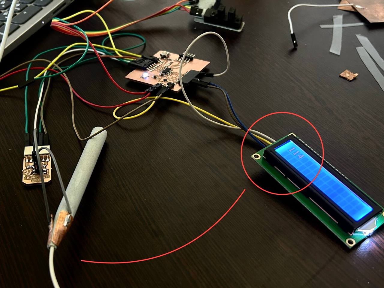
I removed for loop and test it with a single sample.
The values that I got again changed fast. After that again I modified a code and added a code that count average of result that got from 100 samples.
#include <SoftwareWire.h>
const int sda=0, scl=1;
SoftwareWire Wire(sda,scl);
#include <hd44780.h>
#include <hd44780ioClass/hd44780_I2Cexp.h>
hd44780_I2Cexp lcd; // declare lcd object and let it auto-configure everything.
long result;   //variable for the result of the tx_rx measurement.
int analog_pin =10; //  PA5 of the ATtiny1614
int tx_pin =9 ;
void setup()
{
int istatus;

  istatus = lcd.begin(16,2);
  if(istatus)
  {
 // LCD initialization failed.
 // handle it anyway you want
 if(istatus < 0)
 istatus = -istatus;
 lcd.fatalError(istatus); // blinks error if LED_BUILTIN is defined
  }
  pinMode(tx_pin,OUTPUT);      //Pin 2 provides the voltage step
Serial.begin(9600);

}
long tx_rx(){         //Function to execute rx_tx algorithm and return a value
                      //that depends on coupling of two electrodes.
                      //Value returned is a long integer.
  int read_high;
  int read_low;
  int diff;
  long int sum;
  int N_samples = 100;    //Number of samples to take.  Larger number slows it down, but reduces scatter.

  sum = 0;

  for (int i = 0; i < N_samples; i++){
   digitalWrite(tx_pin,HIGH);              //Step the voltage high on conductor 1.
   read_high = analogRead(analog_pin);        //Measure response of conductor 2.
   delayMicroseconds(100);            //Delay to reach steady state.
   digitalWrite(tx_pin,LOW);               //Step the voltage to zero on conductor 1.
   read_low = analogRead(analog_pin);         //Measure response of conductor 2.
   diff = read_high - read_low;       //desired answer is the difference between high and low.
 sum += diff;                       //Sums up N_samples of these measurements.
 }
  return sum/N_samples;
}                         //End of tx_rx function.


void loop() {

result = tx_rx();
//result = map(result,3500,8000, 0, 1023);  //I recommend mapping the values of the two copper plates, it will depend on their size
lcd.print(result);
delay(400);
lcd.clear();
}
This time I got more accurate results.
As I wanted to make a filament runout sensor sensor for my final project I started to test it wit filament. At first I just inside 2 coppers but it was not a good idea because I didn’t manage to fix it properly. After that I tested it pen case I stuck it to the plates outside of the case.
The difference between values was 1. But I think it isn’t enough to make a sensor with a step sensor. I also cut a little bit big 2 plates and put them outside of a little plastic box for testing.
At first, I thought it would work, but after a few seconds, the result on the screen reverted to the same value it displayed when it was empty.

Areg and Maxime helped me a lot giving ideas of different ways of testing and testing it with me. All versions didn’t work well. Rudolf suggested using Transmissive photointerrupter (1A05 Sharp) first I tested it with an oscilloscope. After that, I wrote code to test it and it worked.
#include <SoftwareWire.h>
const int sda = 0, scl = 1;
SoftwareWire Wire(sda, scl);
#include <hd44780.h>
#include <hd44780ioClass/hd44780_I2Cexp.h>
hd44780_I2Cexp lcd;
void setup() {
  pinMode(8, INPUT);
  Serial.begin(9600);
  int istatus;

  istatus = lcd.begin(16, 2);
  if (istatus) {
    // LCD initialization failed.
    // handle it anyway you want
    if (istatus < 0)
      istatus = -istatus;
    lcd.fatalError(istatus);  // blinks error if LED_BUILTIN is defined
  }
}
int counter = 0;
void loop() {
  int sensorVal = digitalRead(8);
  if (sensorVal != 0) {
    counter++;
    lcd.clear();
    lcd.print(counter);
    delay(500);

  }
}
Conclusion
This week I tried to do something that will help my final project, I did a lot of research and learned a lot of new things about capacitive sensors and how they work. I corrected my board and added 5V for the sensor but again I forgot to correct I2C pins that’s why I again added an additional program for I2C pins. I had a lot of failures but in the end, I found the sensor that I can use for my final project as a filament runout sensor.