9. Electronics Design
The assignment for this week was to use an EDA tool to design a development board to interact and communicate with an embedded microcontroller, produce it, and test it.
Group assignment
This week Onik explained us basics of electronics .We understood what a electricity, current, voltage, power. We learnt different protocols and also about PWM signal.
We talked about I2C, SPI, UART protocols. About MOSI,MISO,TX,RX, SCL,SDA, CS, SS pins.
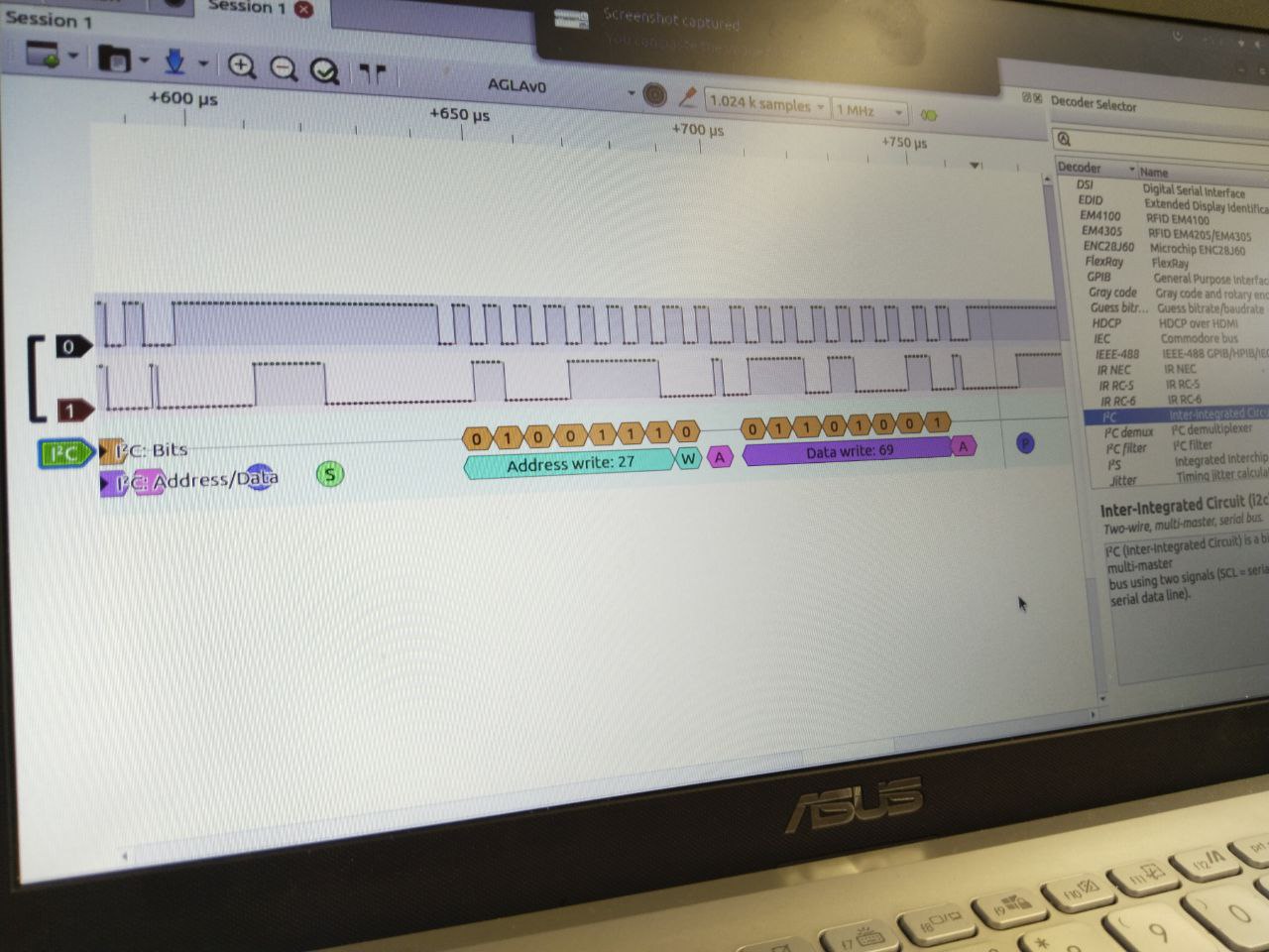
This week we created logic analyzer with Arduino and read the I2C signal from microcontroller to LCD I2C display.
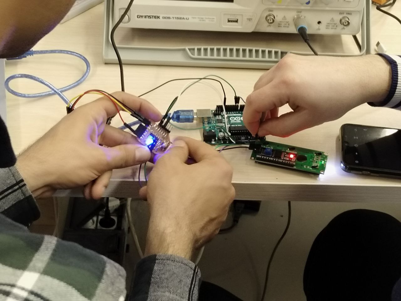
We also saw how PWM signal looked in Oscilloscope.
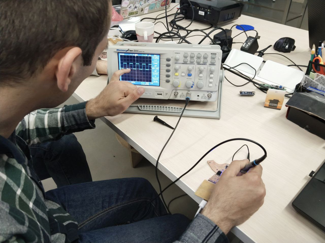
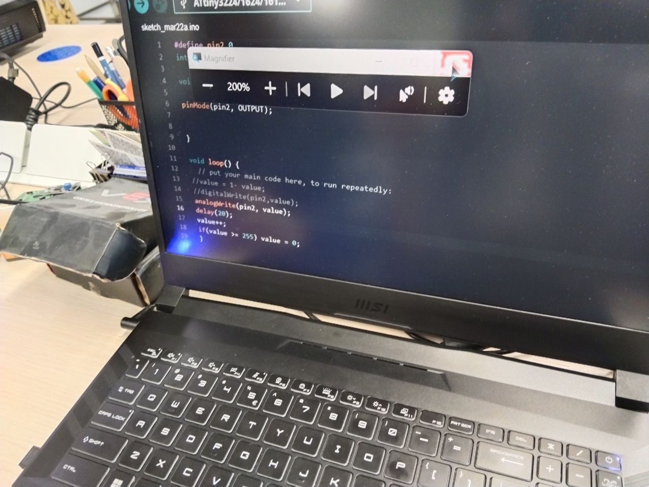
We wrote a program that increases the pin2 (PWM pin) value every 20 milliseconds until the value reached the 255. When it became 255 we changed the value to 0.
Individual assignment
PCB design
Since I was not familiar with the KiCad program, I needed to familiarize myself with the interface first, so I found the KiCad 8 documentation․ Here is the link. - KiCad 8 I had KiCad 7 installed in my computer. I downloaded and installed the Fab library. But with 7.0 version library didn’t work that’s why I installed KiCad 8. Here is the steps of downloading and installing the library. 1. I downloaded the library.

- Stored the folder in C:\Program Files\KiCad\8.0 in this location.
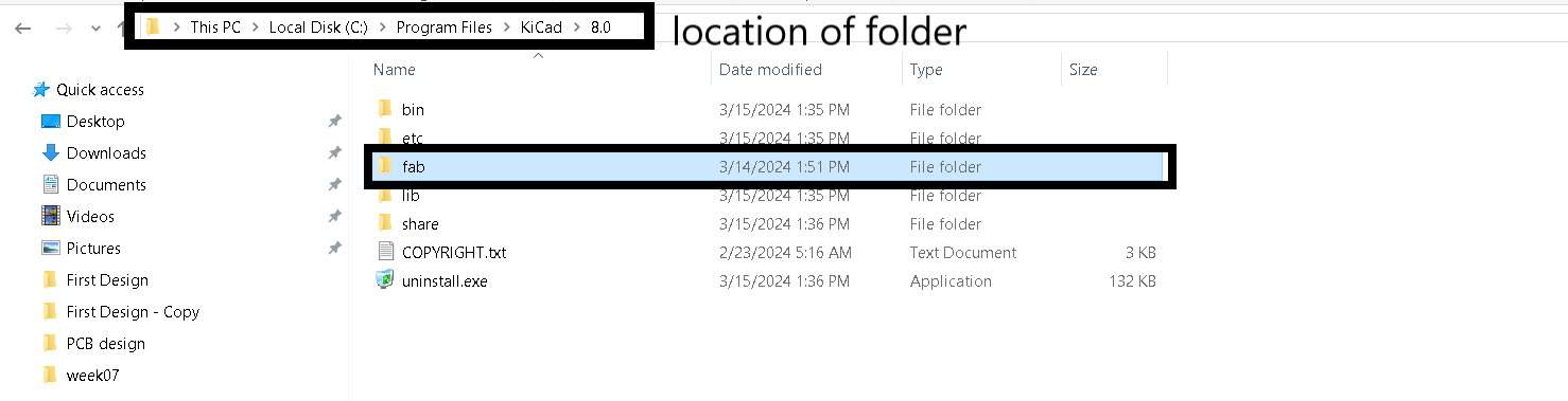
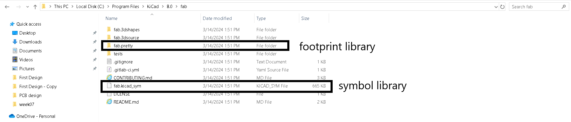
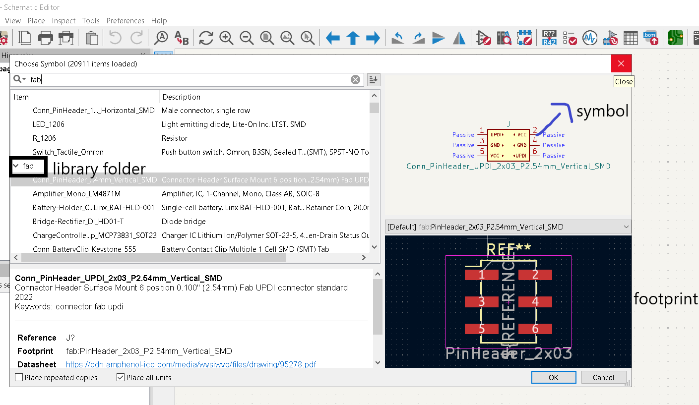
- In this folder are the this symbol library file and footprint library folder.
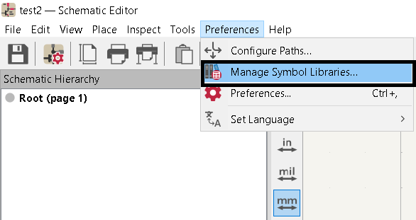
- After that I added the libraries in KiCad. First I added symbol library.

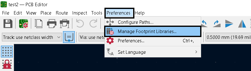
Then I added footprint library.
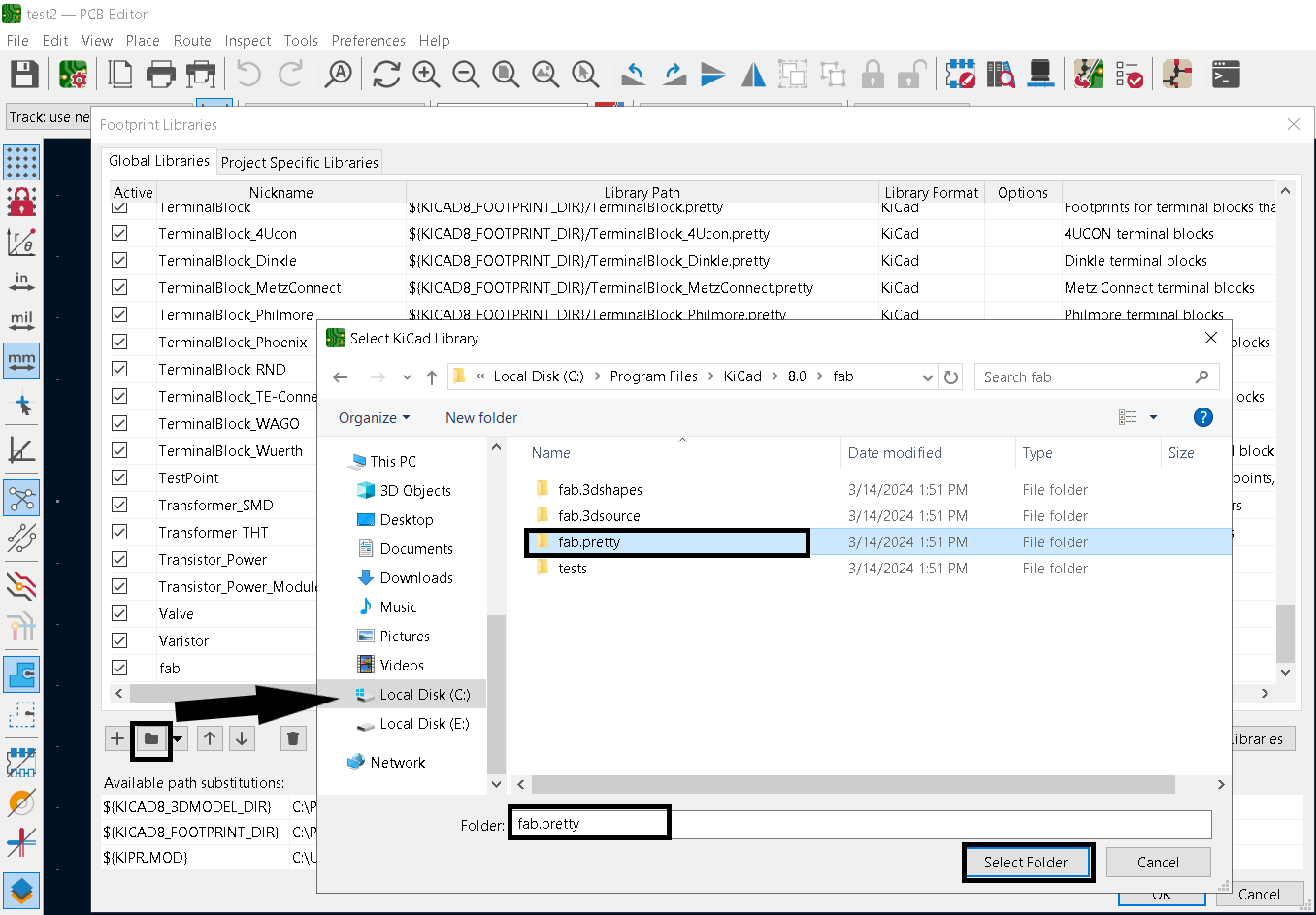
- Then I checked if the libraries were added correctly.
At first, I thought of designing such a board to which I could connect stepper motors and added pins for drivers in the original circuit, but since it was my first experience working with KiCad, the routing was difficult for me.
After realizing that it was going to be hard I temporarily removed driver from my schematic(I will put them back when I design my second board).
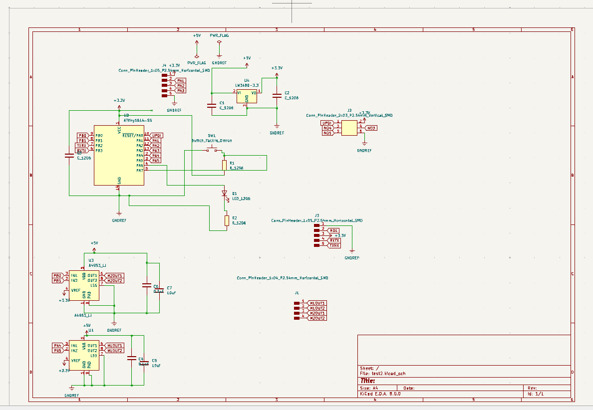
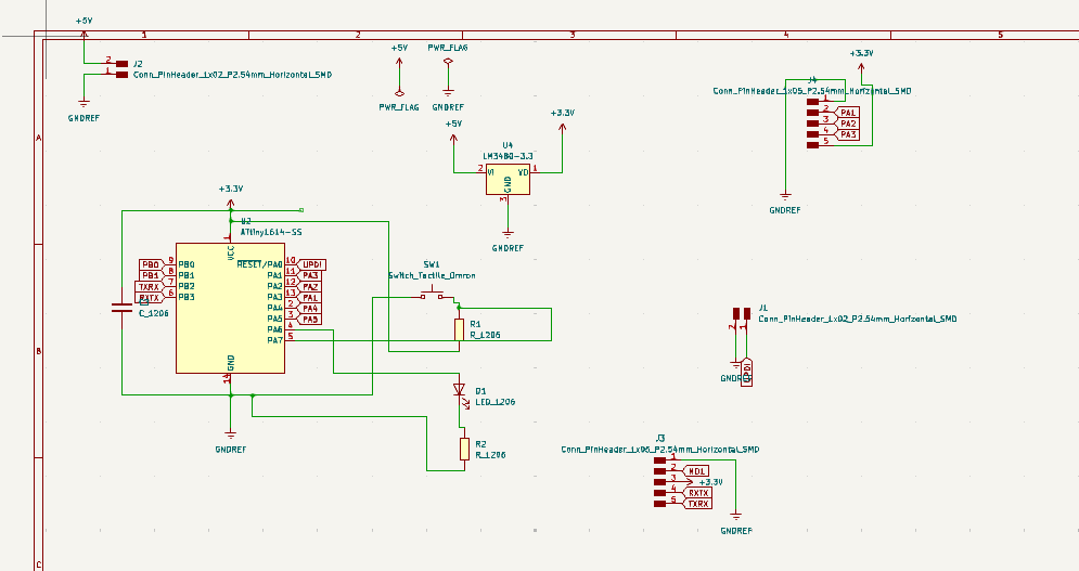
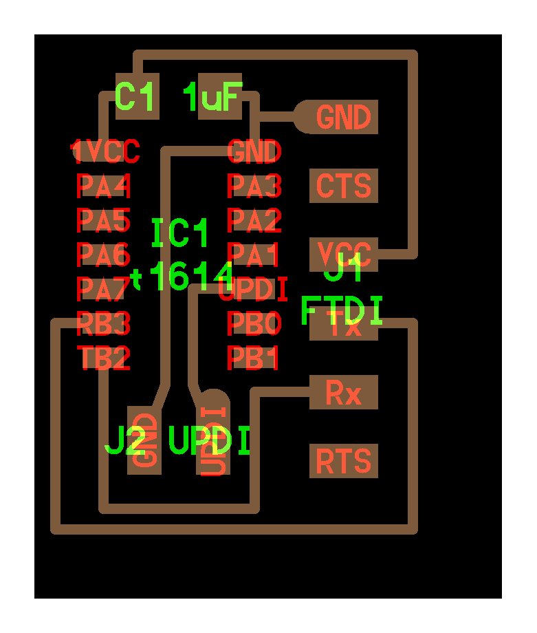
Here is my board schematic for this week.
Here is my board footprint for this week.
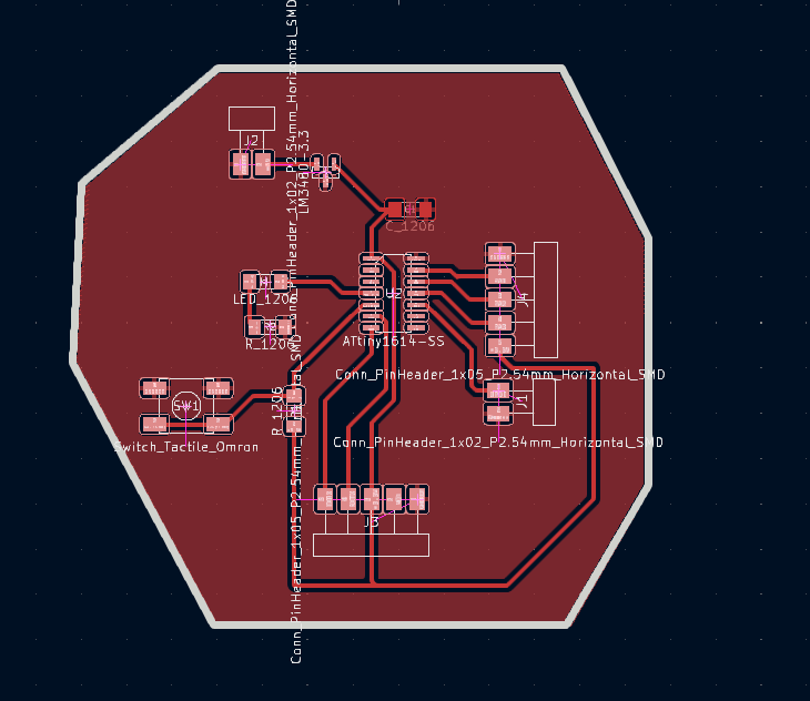
Here are the steps how I designed.
First I decided the components that basic board should contain
-
a microcontroller and its capacitor
-
a voltage regulator with an LED and its resistor and the corresponding capacitors
-
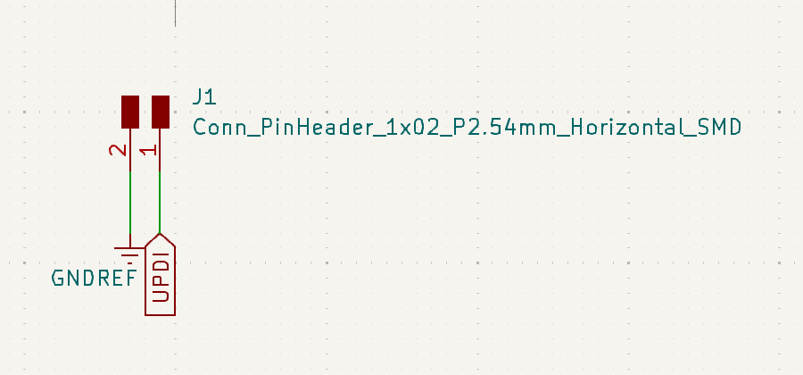
pinheader for programming (UPDI for ATTINY1614)
-
port for Serial communication (FTDI for ATTINY1614)
-
pinheaders for the In/Out pins
-
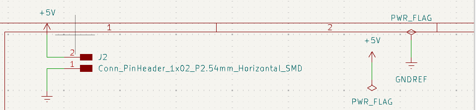
some pinheaders for the Ground and VCC
This list of components was provided by Maxime from Neil’s resource.
I used Attiny 1614 microcontroller. For that I found pinout of the board.
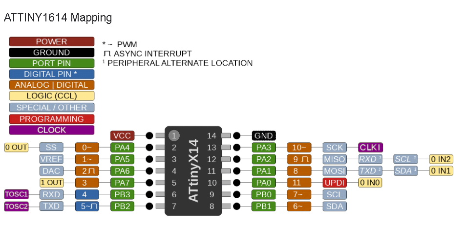
After that I started to add components.
- Microcontroller Attiny 1614.

- Pinheaders for the In/Out pins

-
Pinheaders for programming
-
Pinheaders for Serial communication

- Pinheaders for power supply
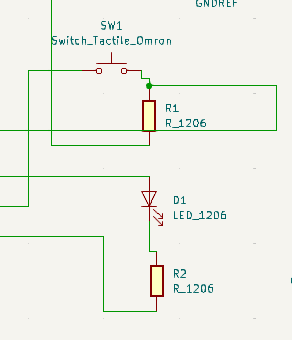
- Led, switch, resistors
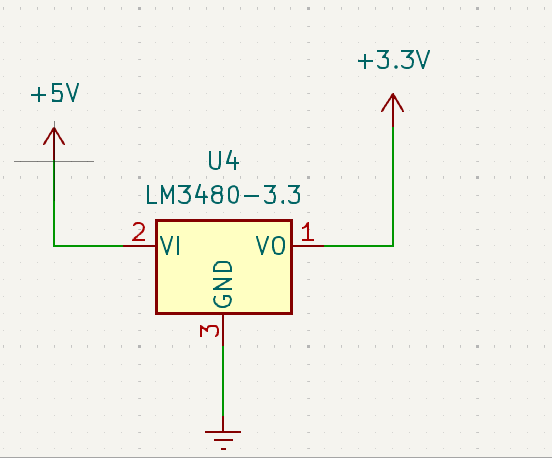
- Voltage regulator
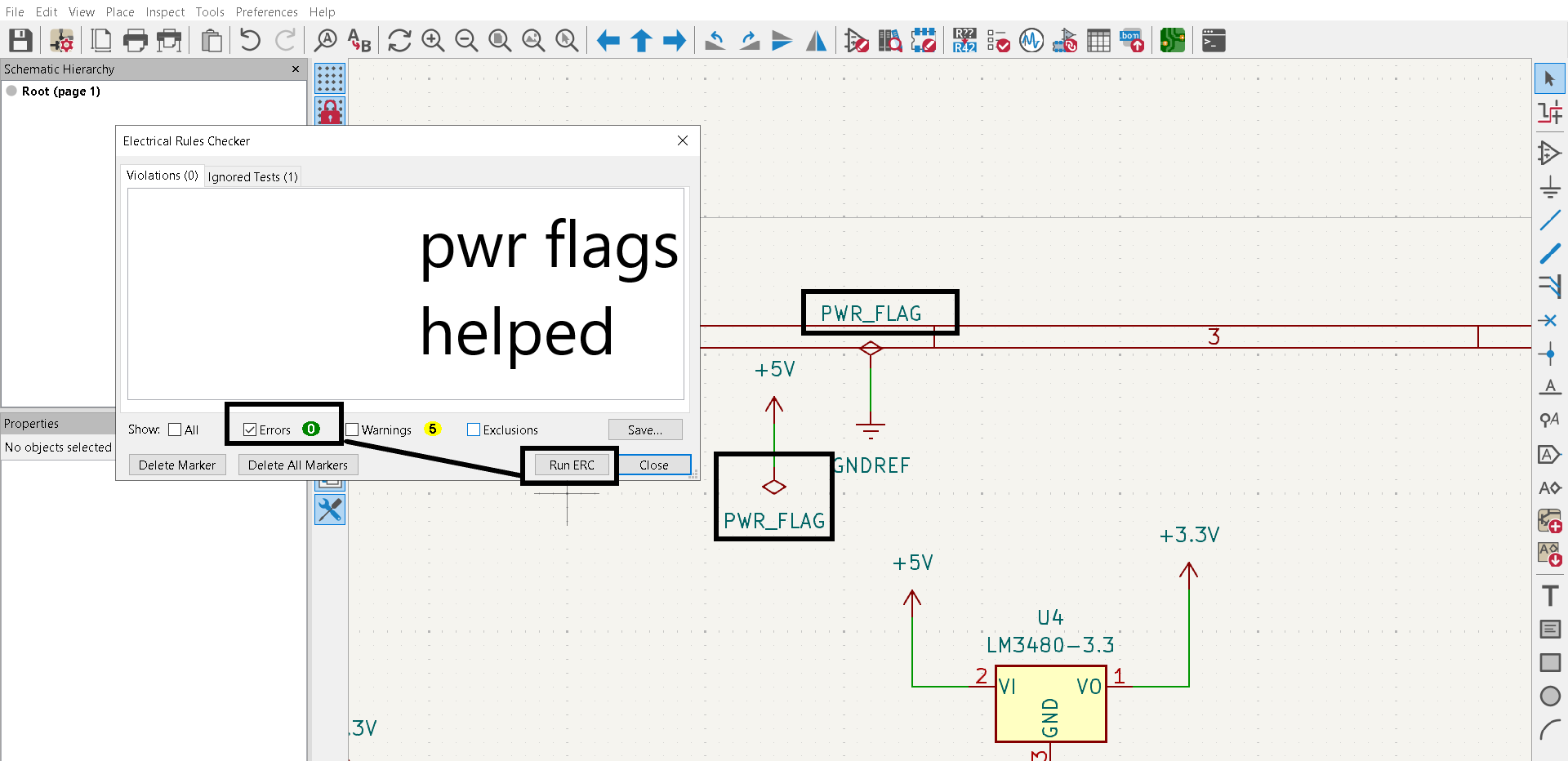
After adding all components and wiring them I did Electrical rule check and found that it had 2 errors.
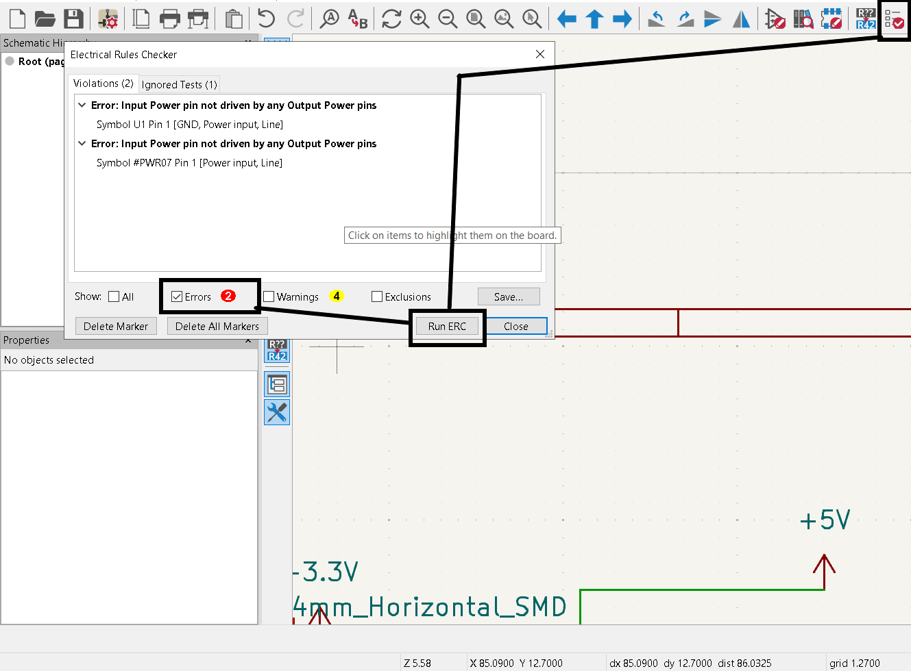
I added power flag for 5V and GND and it helped to solve this problem.
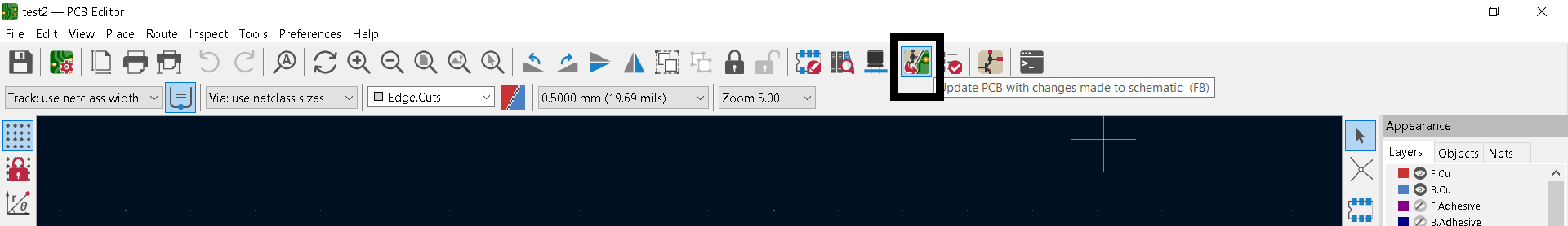
After that I added my schematic in footprint editor with this option.
And after that I needed to connect all components. At first it was really hard and I spent a lot of time but after that I managed to connect all components.

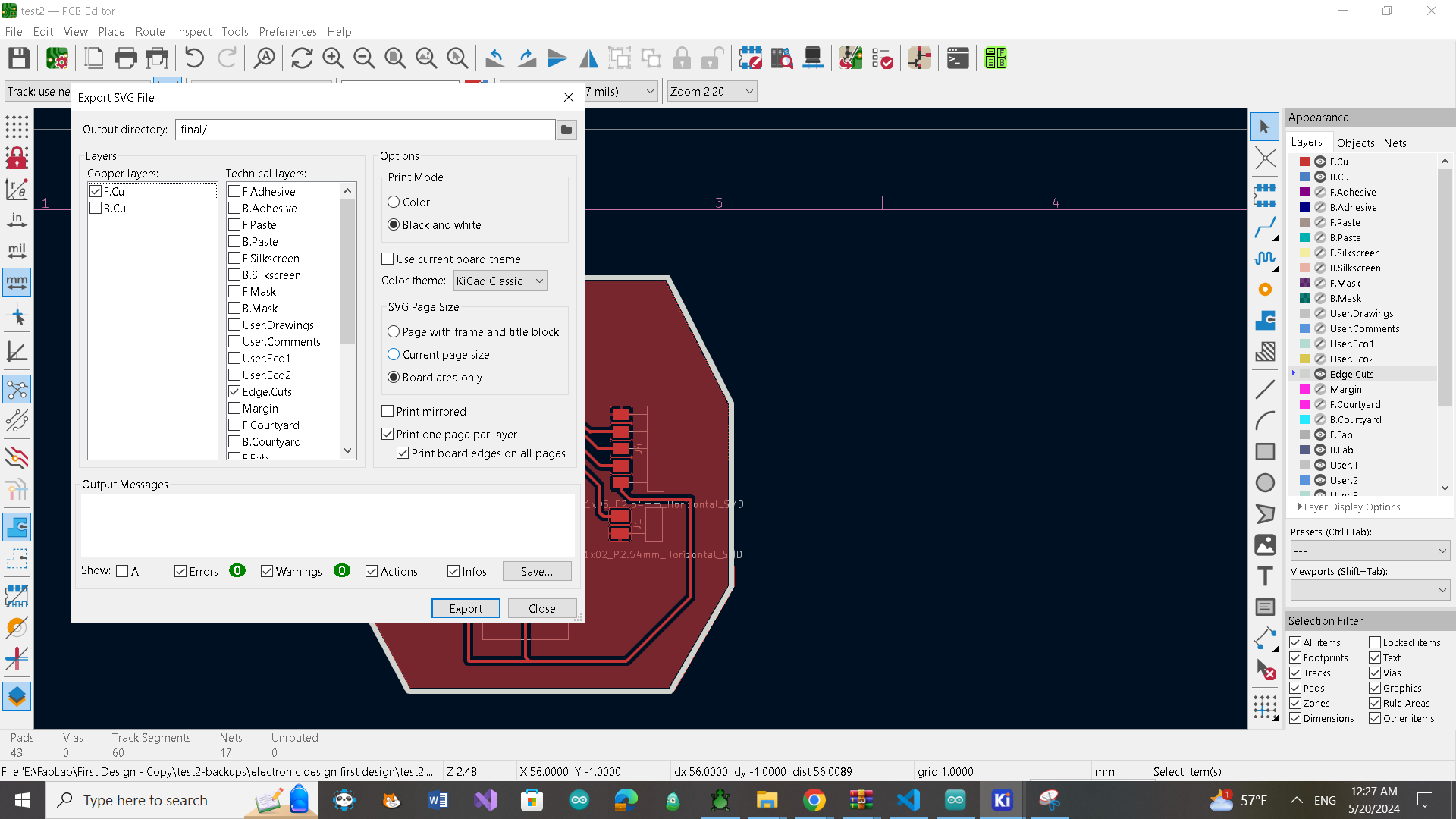
After that I exported SVG files for generating gcode for cutting my board.
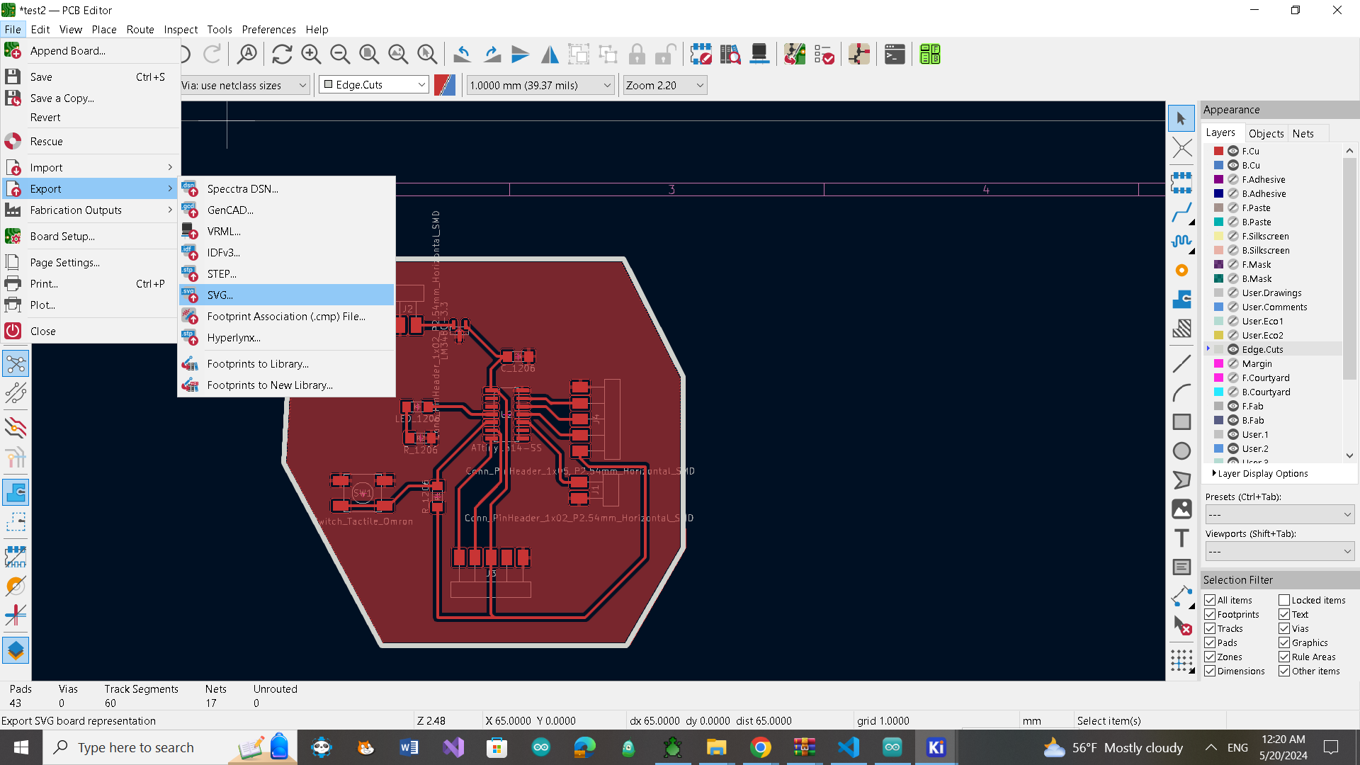
I chose at first copper front layer for making traces and also from technical layer edge cut for making outlines and select the location where I wanted to save.
After exporting files in SVG format I opened modsproject webpage for generating gcodes.
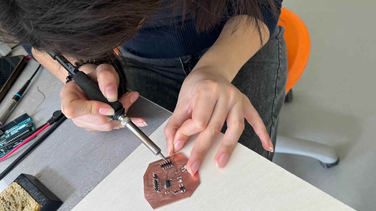
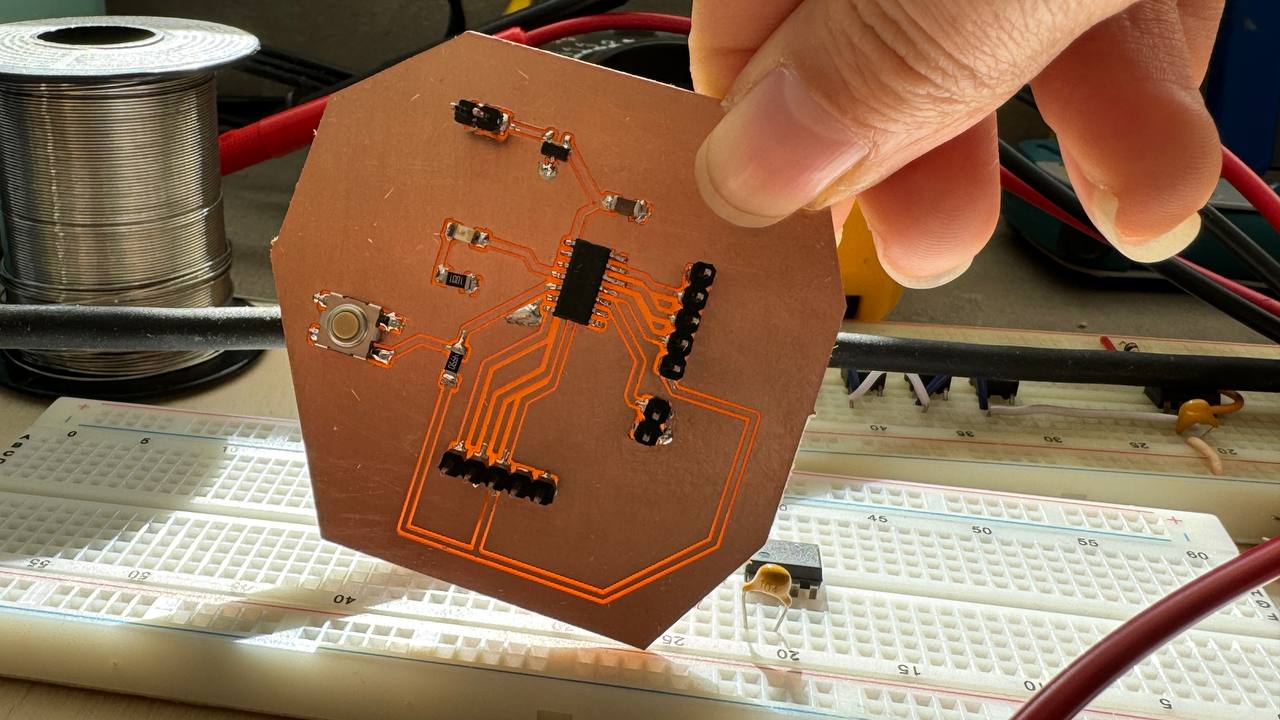
PCB production and soldering
I did the same steps that I describe in Electronic production week. When my board was ready I started to look for all components I needed and started soldering.
Programming
Programming it with Atmel programmer was impossible because the Port of the board can not be found in Arduino IDE.
 I downloaded Microchip studio program but it didn’t help and I found 2 solution.
First solution was program it with Arduino. I found a tutorial UPDI Programmer using Arduino Uno for ATtiny that was really helpful I followed the steps and it worked.
I wrote code for blinking led for testing my board.
I downloaded Microchip studio program but it didn’t help and I found 2 solution.
First solution was program it with Arduino. I found a tutorial UPDI Programmer using Arduino Uno for ATtiny that was really helpful I followed the steps and it worked.
I wrote code for blinking led for testing my board.
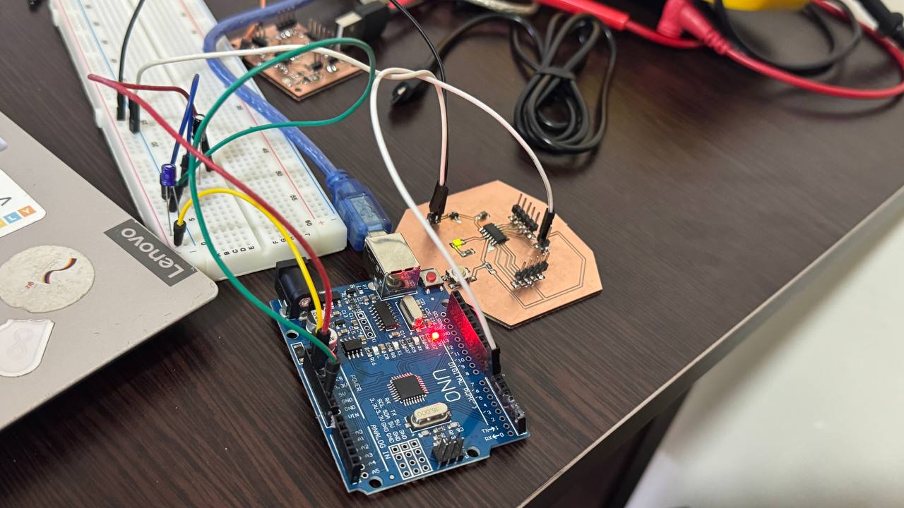
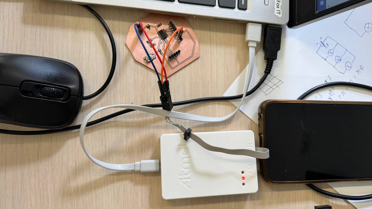
I also programed it with Quentorres board. I tested it with Quentorres and it was much easier because for programming with Arduino Uno board I needed also breadboard for wiring capacitor and resistor. Here are steps how I did it.
-
I opened the preferences window from the Arduino IDE. Go to File -> Preferences.
-
On the preferences window, locate the “Additional Board Manager URLs” text box and I entered http://drazzy.com/package_drazzy.com_index.json into the field as shown below and click the OK button

-
Next, I opened the Arduino board manager, then tools->Boards->Boards manager
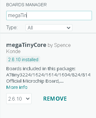
-
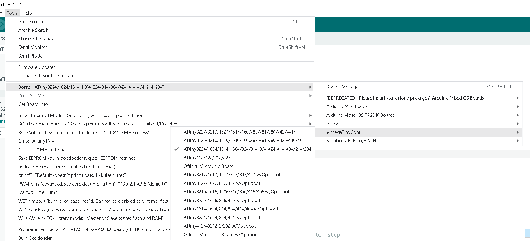
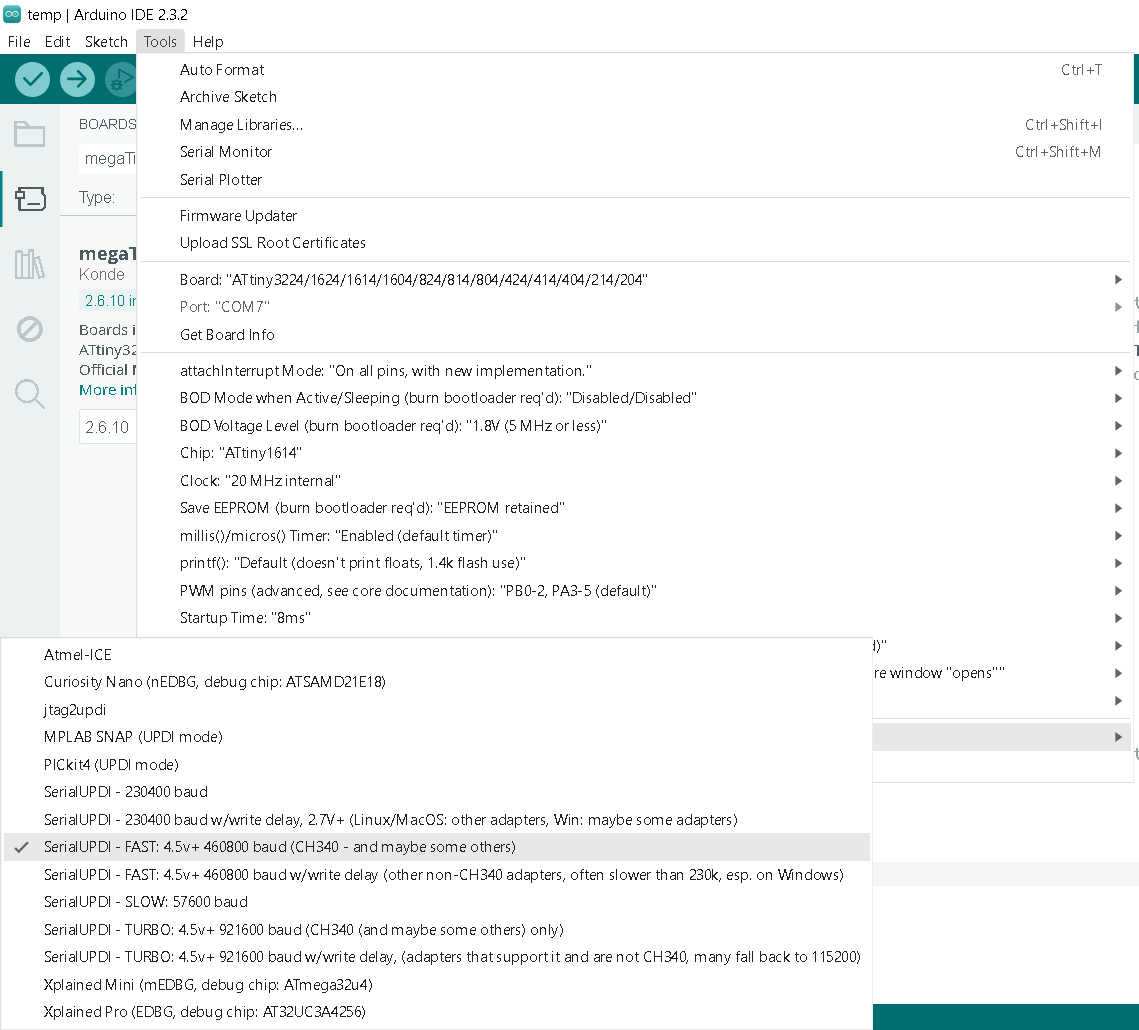
After that I select the board.
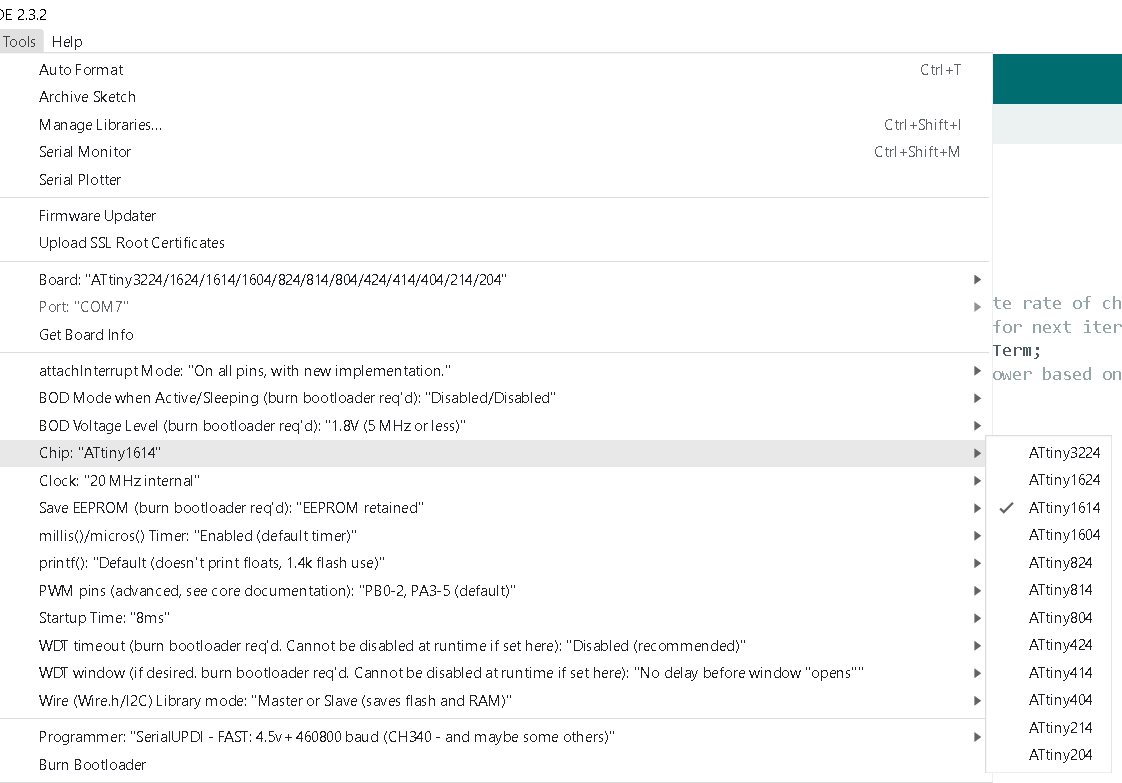
- Select the Chip.
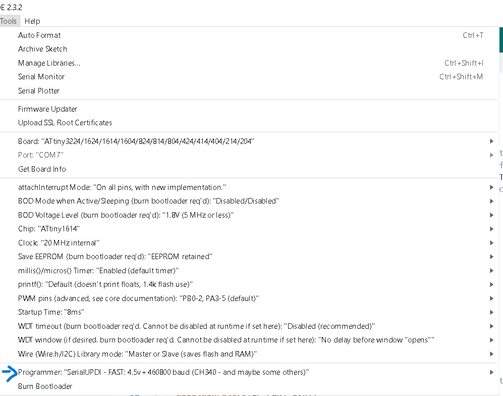
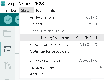
- After that select the programmer and upload the code using programmer.
Here is the code I uploaded.
int ledPin= 2;
void setup() {
  pinMode(ledPin, OUTPUT);
}

void loop() {
  digitalWrite(ledPin, HIGH);  // turn the LED on (HIGH is the voltage level)
  delay(1000);                      // wait for a second
  digitalWrite(LedPin, LOW);   // turn the LED off by making the voltage LOW
  delay(1000);                      // wait for a second
}
Conclusion
This week was very interesting because first time I designed my board, I learnt a lot during this week. How I need design, make and program. I found already mistakes that I did. The next week I decided made better board. The most challenging part was programming because at first I thought it would be easy but I couldn’t do it with Atmel programmer but due to it I learned how can I program it with Arduino Uno board and with Quentorres board.