3. Computer Aided design
This week, I explored 2D and 3D graphics tools to make a model for our final project. Modeling isn’t my strongest skill, so achieving the exact models was challenging for me. Nonetheless, I’m optimistic that with dedicated practice, my skills will surely improve.
2D graphics
Vector and Raster graphics
Vector design is a type of digital graphic that uses lines and shapes to create design. This type of graphic is resolution-independent it means it can be scaled up or down and without any quality loses. This is because the mathematical formulas recalculate every time the image is resized. Programs like Adobe Illustrator, CorelDRAW, and Inkscape are for vector graphics. T On the other hand, raster graphics, also known as bitmap graphics, are consist of individual pixels. Each pixel is assigned a specific color, and together, they become a complete image. When you zoom in on a raster image, you can see the individual pixels that make up the image. Raster graphics are created using programs like Adobe Photoshop, GIMP, and Corel PaintShop Pro. These programs are excellent for creating detailed and realistic images. I’ve used Adobe Illustrator and Adobe Photoshop, but not at a professional level. Working with vector graphics comes naturally to me because, even without strong drawing skills, I can create illustrations using simple geometric shapes.
Since I was already familiar with the tools and interface of Adobe Illustrator, I chose to give the Inkscape program a try this time. I wanted to get to know it better and figure out which one is more user-friendly for me.
Inkscape
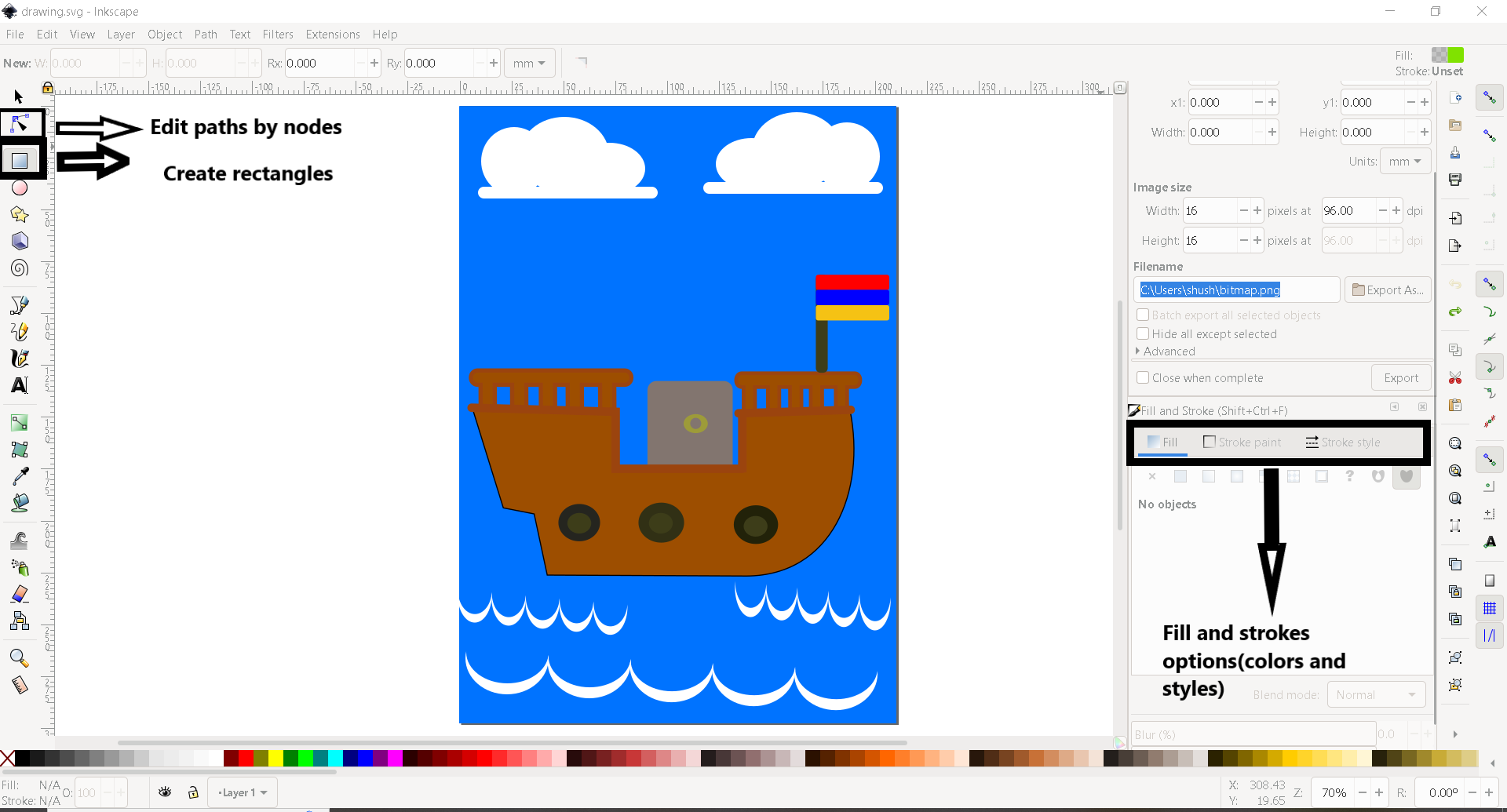
Initially, I sketched the appearance of the ship I aimed for, then I attempted to figure out the basic geometric shapes it should be composed of. The primary section of the ship will be shaped by adjusting the rectangle using the two highlighted tools in the picture(Create rectangles and node tool).
It was also important for me to understand how the Fill and Stroke menu works and available options there.

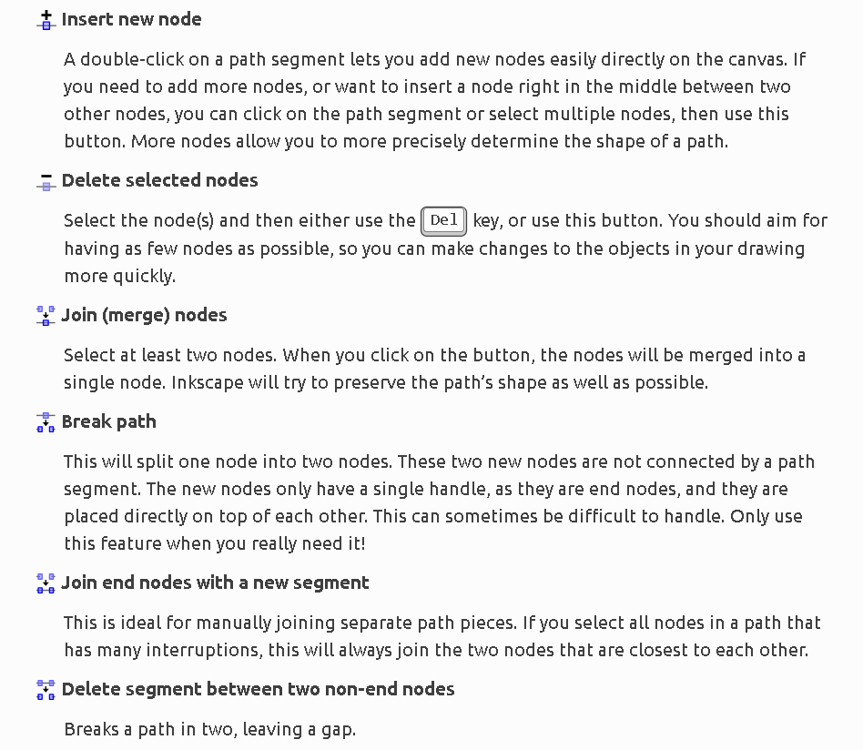
Initially, I have to change the polygon into a path so that I can add points and adjust the part I want.

Here are the essential tools for dealing with nodes. Inkscape nodes
I used tools like Flip, Rotate, and layer alignment.

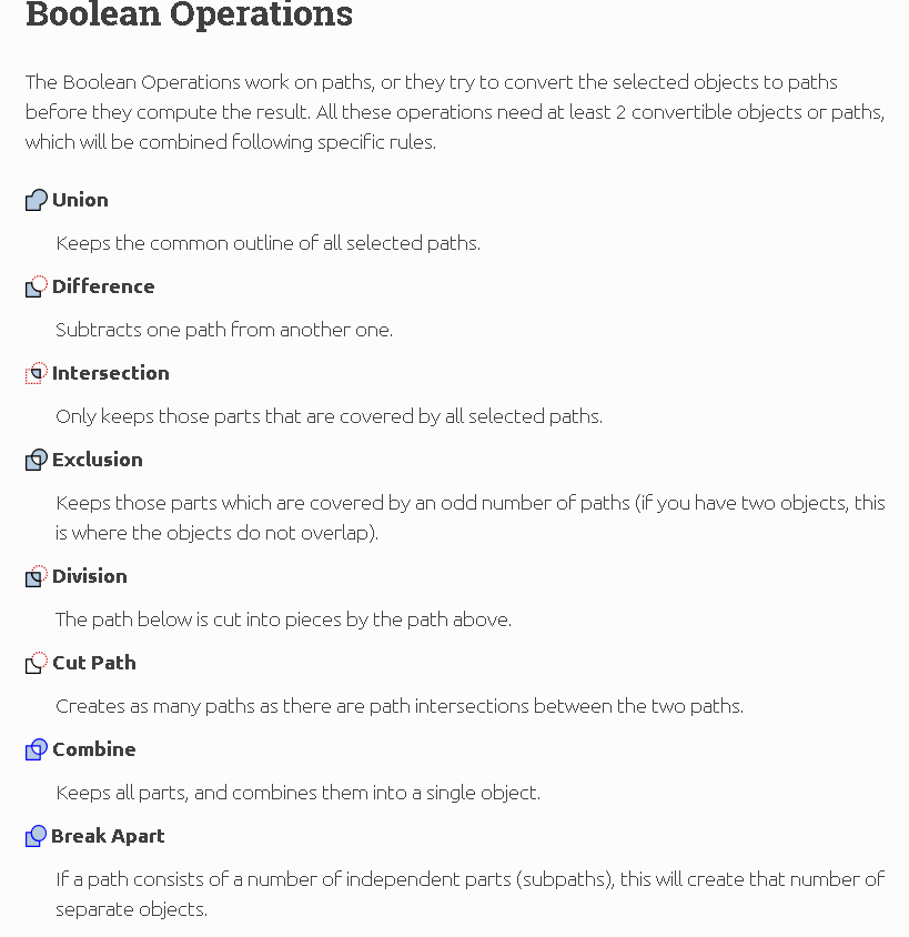
To achieve the final appearance of my ship, I used the Boolean Operations tools, specifically the Union and Difference options, along with the Group tool to bring together all the ship’s parts.
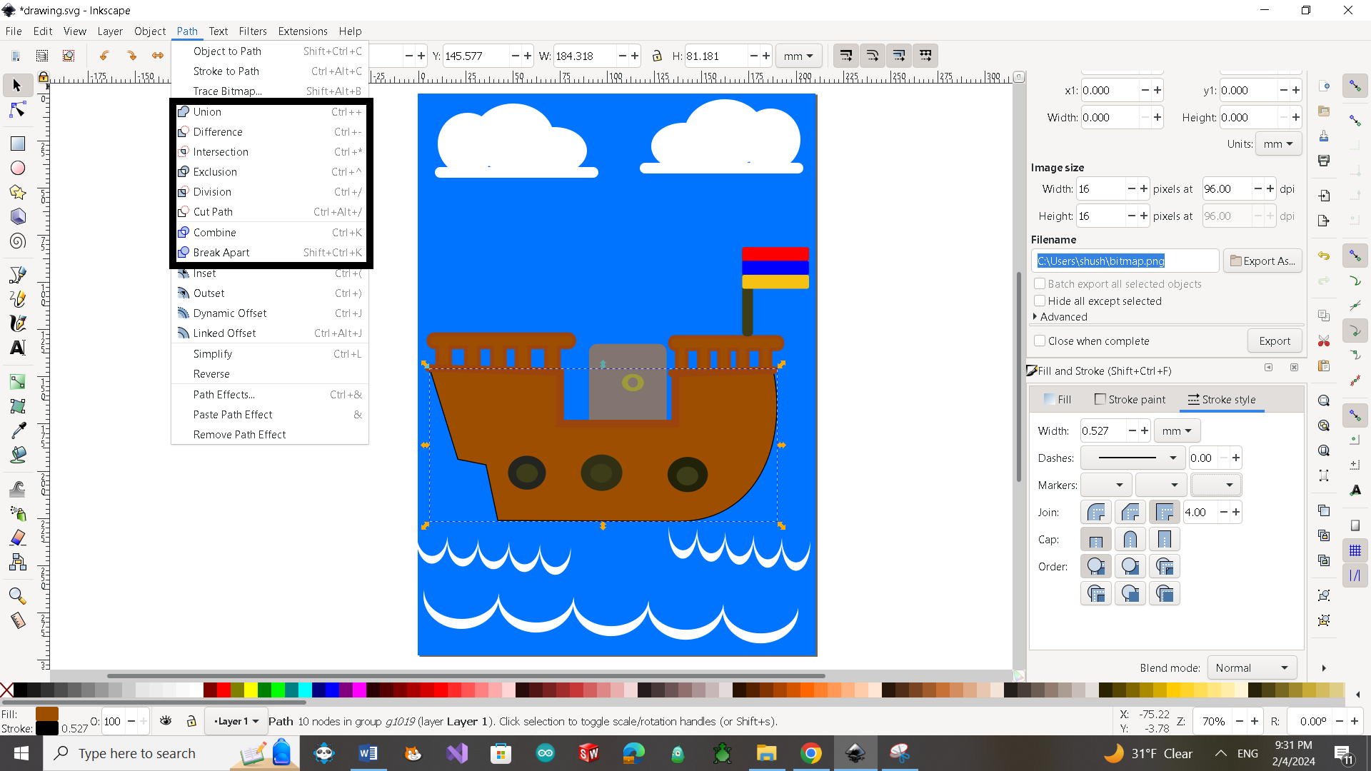
The second version of the ship looks relatively better to me than the first one. I concentrated more on the outcome rather than just using the basic tools.

GIMP
As I mentioned, I was familiar with Adobe Photoshop, and I knew it’s mostly used for editing pictures. It has different filters, and you can adjust color brightness, contrast, and saturation to achieve the desired tone in your picture. I also checked out the GIMP program, its available filters, and basic tools through the following links.
I merged the image of the ship I designed and rendered using the SolidWorks program with a picture of the clean lake that I downloaded from this webpage Lake․ I added some filters and adjusted the brightness and contrast of the lake picture.

3D graphics
FreeCad
FreeCAD is an open-source parametric 3D modeler made primarily to design real-life objects of any size. Parametric modeling allows you to easily modify your design by going back into your model history and changing its parameters. FreeCAD is a multiplatform (Windows, Mac and Linux), highly customizable and extensible software. It reads and writes to many open file formats such as STEP, IGES, STL, SVG, DXF, OBJ, IFC, DAE and many others, making it possible to seamlessly integrate it into your workflow.
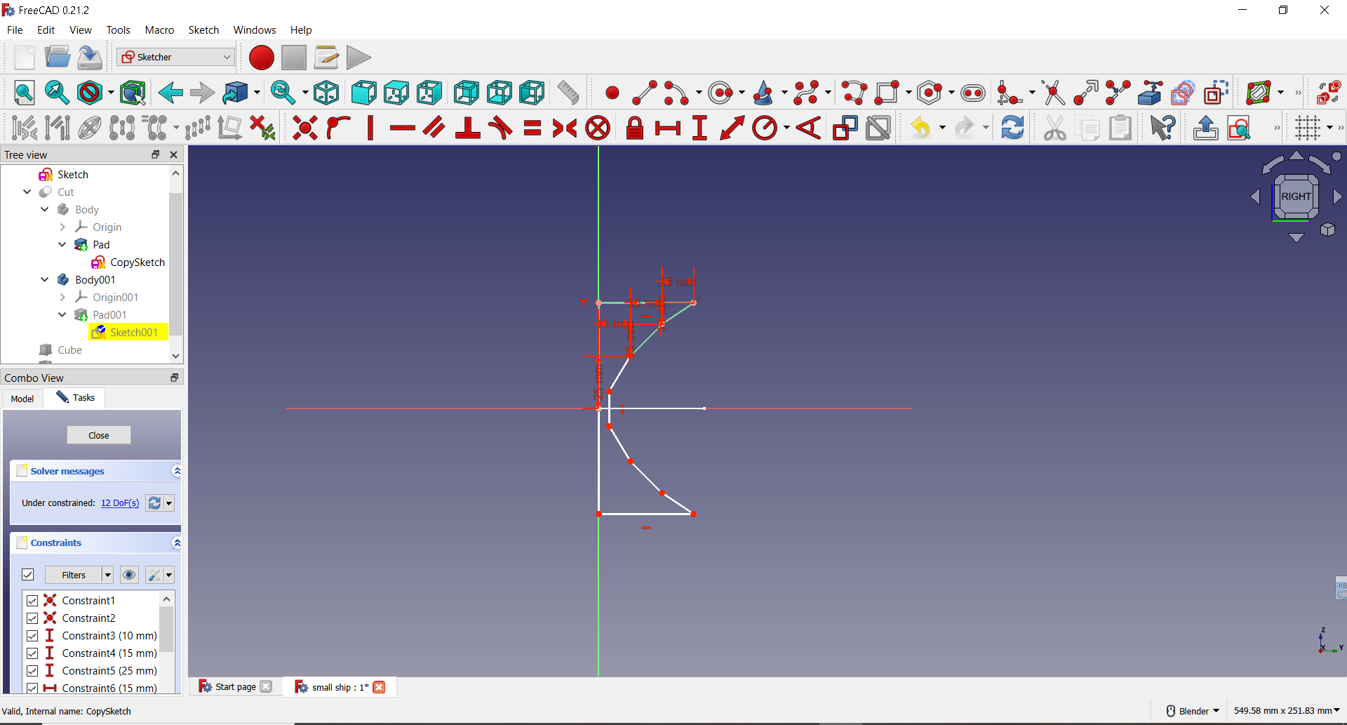
When I used FreeCad, the first step was to decide which Workbench to use because the tools vary depending on it. For example the FreeCAD Sketcher Workbench is used to create 2D sketches intended for use in other workbenches. 2D sketches are the starting point for many CAD models. To create the ship model in FreeCad, I started with the Sketcher Workbench and later used the Part and PartDesign workbenches as well. Let’s start with Sketcher Workbench․ I drew right part of sketch and after it used symmetry tool to create left side.

After that selected Part design workbench and used Pad tool.
 Then I drew the second sketch.
After that I used Pad tool again for my second sketch.
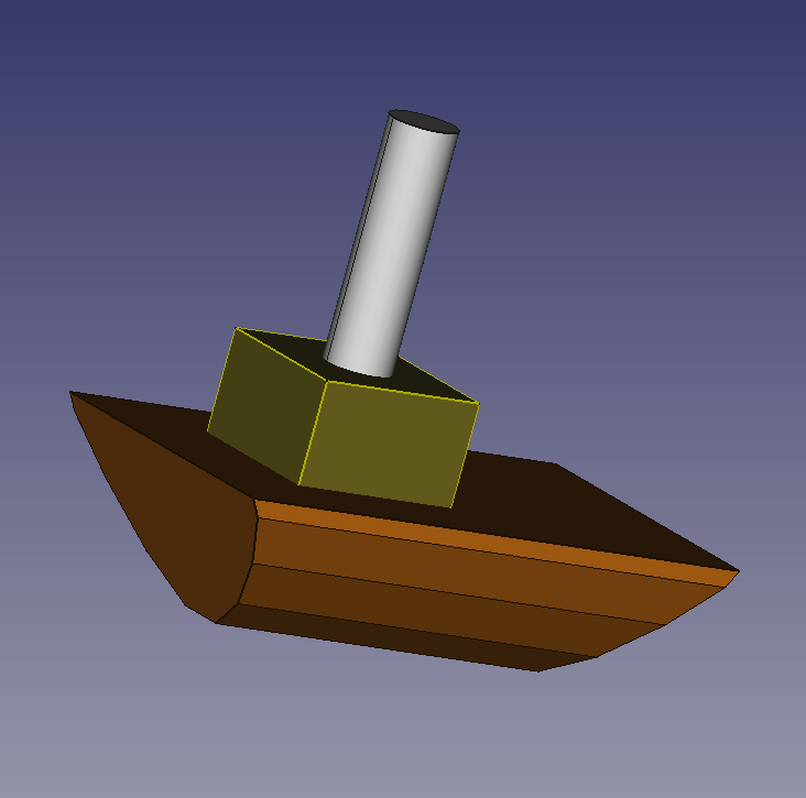
Here are 2 bodies of my design.
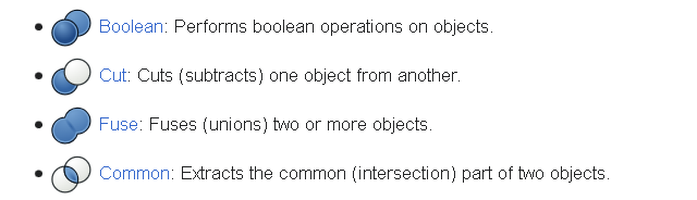
 And finally I merged them using Part Workbench Cut tool.
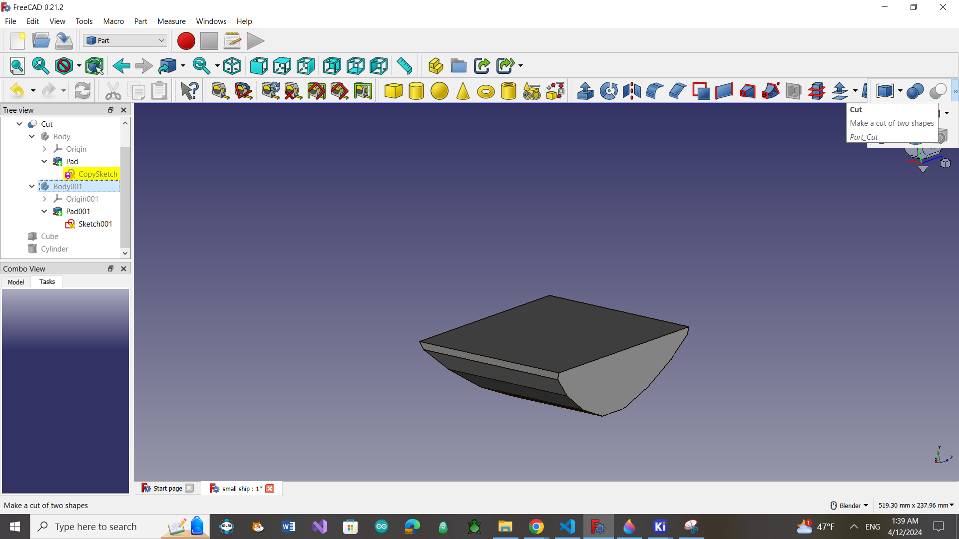
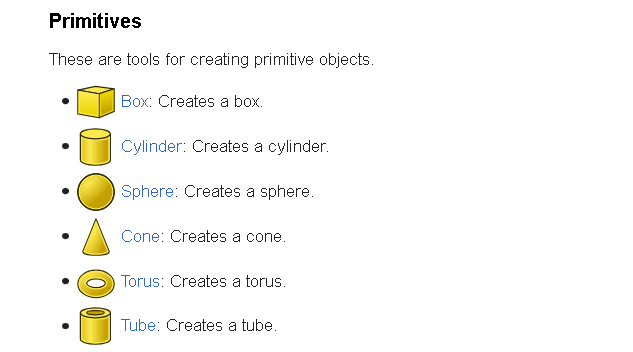
I also added Cube and Cylinder from part workbench for final result.

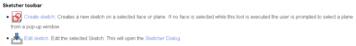
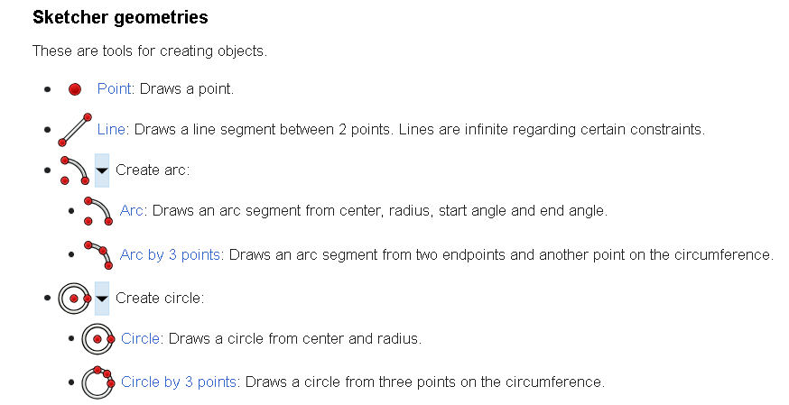
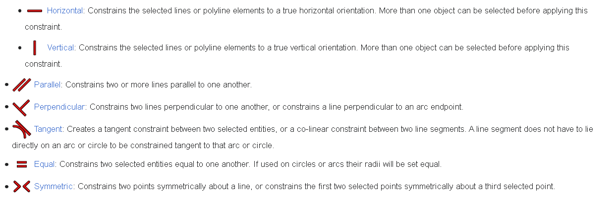
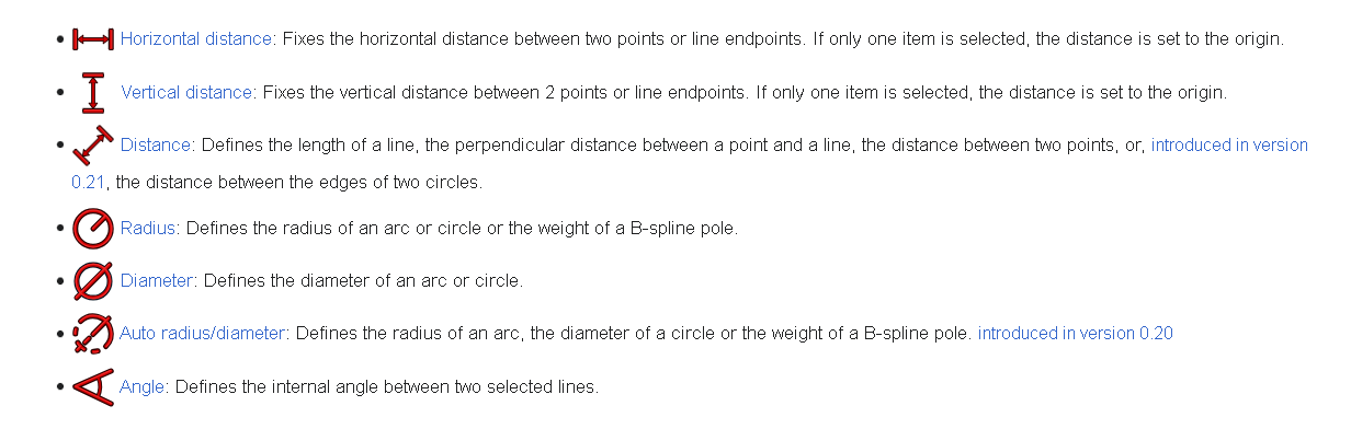
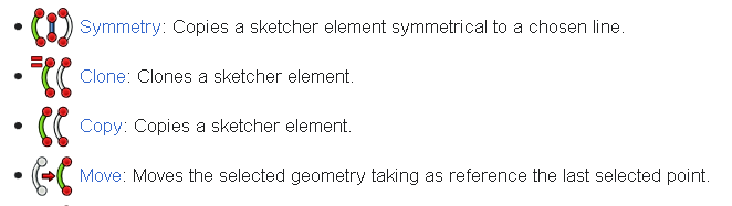
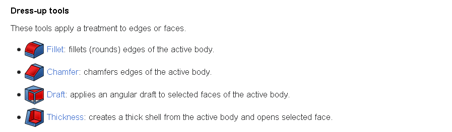
Here are some tools and it description from FreeCad documentation that I used during the design, and some of them have a wide range of applications.
Sketcher toolbar
FreeCad Sketcher workbench documentation
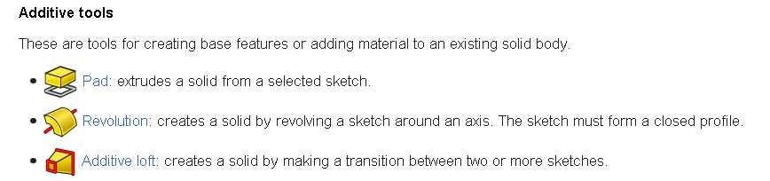
Part Design toolbar
FreeCad Part Design workbench documentation

Part toolbar
FreeCad Part workbench documentation
OpenSCAD
OpenSCAD is software for creating solid 3D CAD models. It is free software and available for Linux/UNIX, Windows and Mac OS X. Unlike most free software for creating 3D models (such as Blender) it does not focus on the artistic aspects of 3D modelling but instead on the CAD aspects. Thus it might be the application you are looking for when you are planning to create 3D models of machine parts but pretty sure is not what you are looking for when you are more interested in creating computer-animated movies.
OpenSCAD is not an interactive modeller. Instead it is something like a 3D-compiler that reads in a script file that describes the object and renders the 3D model from this script file. This gives you (the designer) full control over the modelling process and enables you to easily change any step in the modelling process or make designs that are defined by configurable parameters.
When exploring the OpenSCAD program, I took a different approach. I downloaded existing work and tried making some changes, divided program into parts to understand the function of each part. Here is the link of the original file. OpenSCAD original file

In OpenSCAD, the cube() function is used to create a 3D rectangular prism (a cube) by specifying its dimensions. The basic syntax for the cube() function is:
cube([10, 10, 10]);
In OpenSCAD, the cylinder() function is used to create a 3D cylinder. The basic syntax for the cylinder() function is:
cylinder(h = height, r = radius, $fn = resolution);
cylinder (h = 20, r = 5, $fn = 50);
In OpenSCAD, the scale() function is used to scale or resize a 3D object along the x, y, and z axes. The basic syntax for the scale() function is:
scale([2, 1, 1])
    cube([10, 10, 10]);
This would create a scaled cube with dimensions 20x10x10.
In OpenSCAD, the translate function is used to move or translate objects in three-dimensional space. It takes a vector as an argument, which represents the displacement along the x, y, and z axes. The syntax is:
translate([10, 5, 3])
    cube([2, 2, 2]);
This code would translate a cube by 10 units along the x-axis, 5 units along the y-axis, and 3 units along the z-axis. In OpenSCAD, the union() function is used to combine multiple 3D objects into a single object by taking the union of their volumes. It creates a single object that encompasses the entire space occupied by the combined objects. The syntax is:
union() {
    cube([2, 2, 2]);
    translate([3, 0, 0])
        sphere(1);
}
In this example, the union() function combines a cube and a translated sphere into a single object.
SolidWorks
SolidWorks is a 3D parametric design software that is used to design all sorts of products such as automobiles, marine equipment, airplane parts, cell phones, cameras, furniture, electrical assemblies, glasses, lighting fixtures, toys, vacuum cleaners, or any other like product we can think of. Having prior experience with SolidWorks made it easier for me to navigate and use the tools compared to FreeCAD, as I was already familiar with the functionalities and interface.
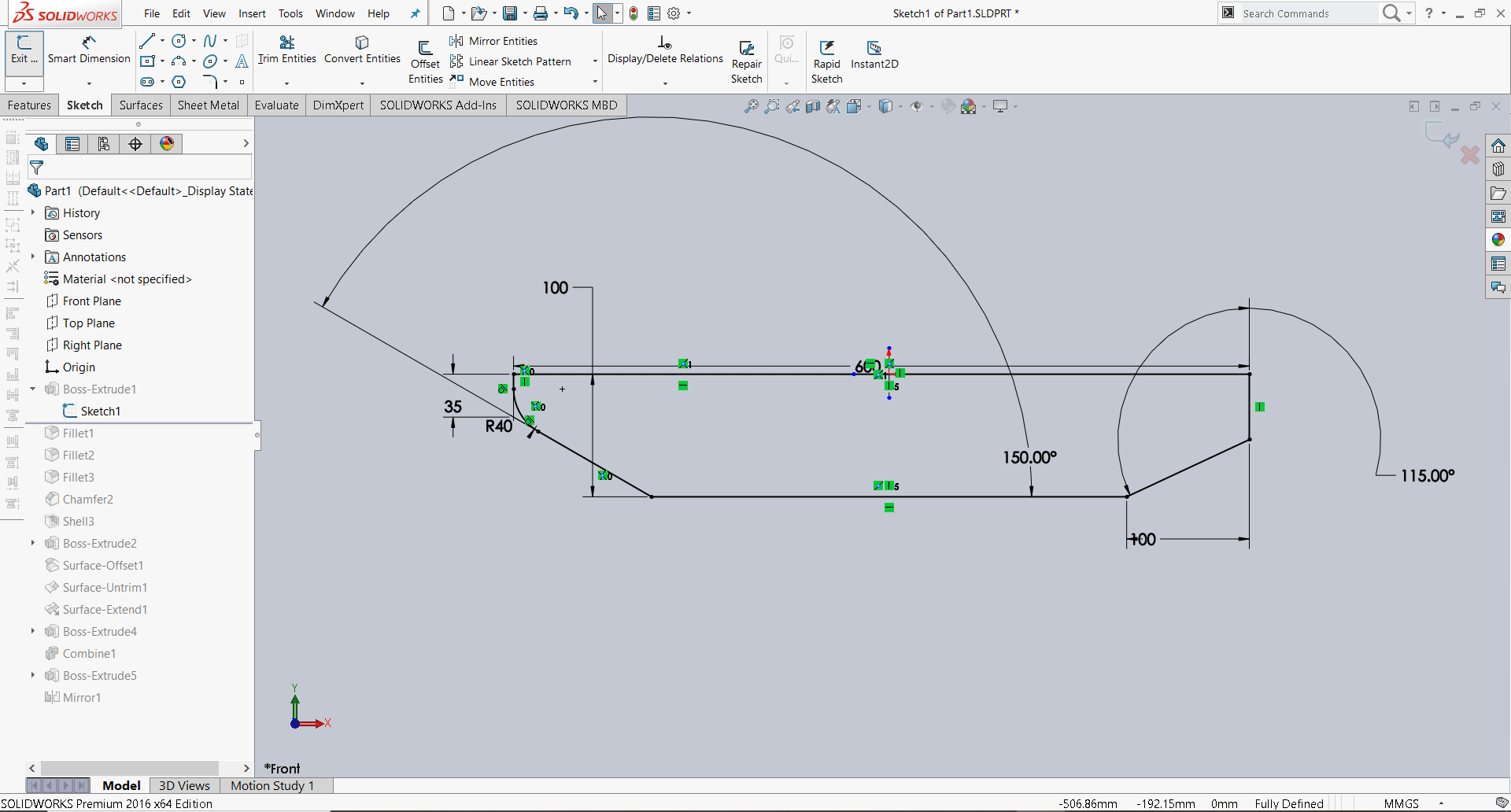
At the first, I created the initial sketch for my project, applying constraints and specifying dimensions to define the geometry.
Here’s a description and application of the main tools I utilized in my project.
The Smart Dimension tool in SolidWorks simplifies the dimensioning process.
The chamfer tool creates a beveled feature on selected edges, faces, or a vertex.
Fillet/Round creates a rounded internal or external face on the part. You can fillet all edges of a face, selected sets of faces, selected edges, or edge loops.
Shell is a great tool for parts requiring a uniform thickness because it is as easy as Fillet or Chamfer but can create some complex uniform thickness parts. The Offset Surface tool creates a new surface body from an existing set of faces. The faces may be solid or surface faces.
With Untrim Surface, you can patch surface holes and external edges by extending an existing surface along its natural boundaries.You can also extend the natural boundaries of the surface by a given percentage, or connect the end points to fill the surface. Use the Untrim Surface tool with any imported surface or surfaces that you create.You can extend a surface by selecting an edge, multiple edges, or a face.
In a multibody part, you can combine multiple bodies to create a single body.
In SOLIDWORKS, we have the ability to generate a mirrored version of a part for the opposite hand using the mirror pattern tool.

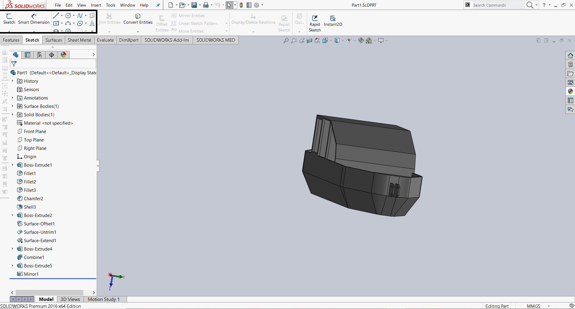
Rendering
Rendering is the finalization process of a digital image or a 3D model using computer software. It lets users bring together the visuals, from the shadows and lighting effects to the textures, and generate the final result. Rendering is used for various digital projects, including video games, animated movies, and architectural designs.

Conclusion
In this week I have learned a lot about Computer-Aided Design (CAD) and how to use different software like Inkscape,GIMP, FreeCAD, and SolidWorks. I discovered Adobe Illustrator to be more user-friendly due to my prior experience with the program(this week I used only Inkscape). However, for those unfamiliar with either software, Inkscape’s menu and tools are more accessible and beginner-friendly.
GIMP was interesting for me but I think I need a little bit more time for exploring the functionality of the program. FreeCAD is a good tool for creating 3D models.At first the interface was very confusing, but after using it started be easier. I find the SolidWorks interface easier to use even though it has a more specialized application. However, since modeling is not one of my strong points, it was easiest for me to use ՕpenSCAD, because the models were created there using code.