10. Output devices
Group assignment
Our group assignment was to measure the power consumption of an output device.
We did it with Onik. At first he explained as what is power consumption and how we can measure it.
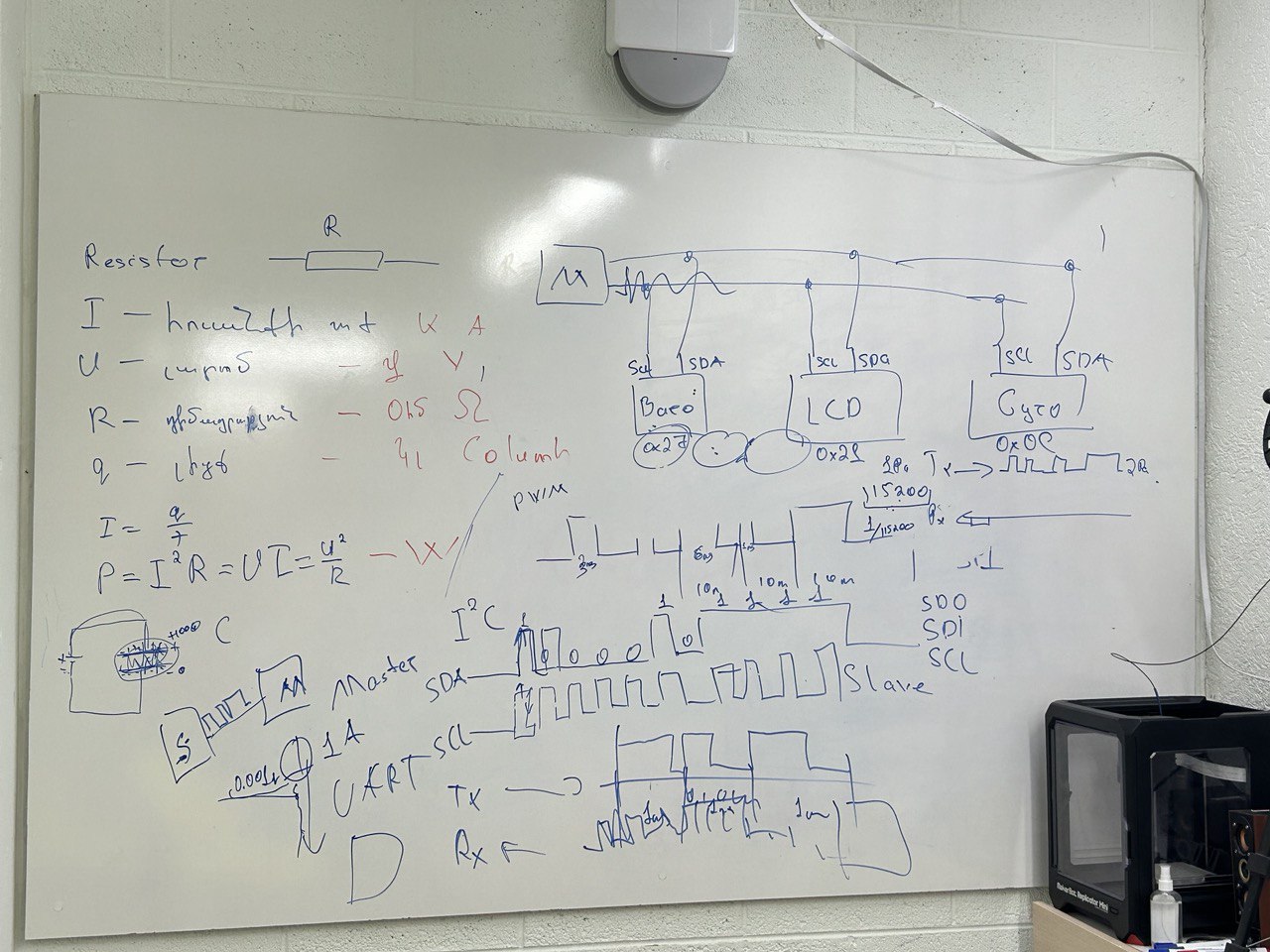
We can do it wit this formula. P = V x I
Power P = Watt [W]
Voltage V = Volt [V]
Current I = Ampere [A]
After that we start measure it with DC motor. DC motor are type of motor that uses Direct current to produce mechanical force.It has two wires + and - if we connect it in opposite order motor will start rotate in reverse direction. The nominal voltage for DC motor typically 12V or 24V. The speed of rotation is directly proportional of the input voltage. We started measure it and have the voltage and the current with bench power supply. We put 12V and the max allowed current is 3.2 Amperes.
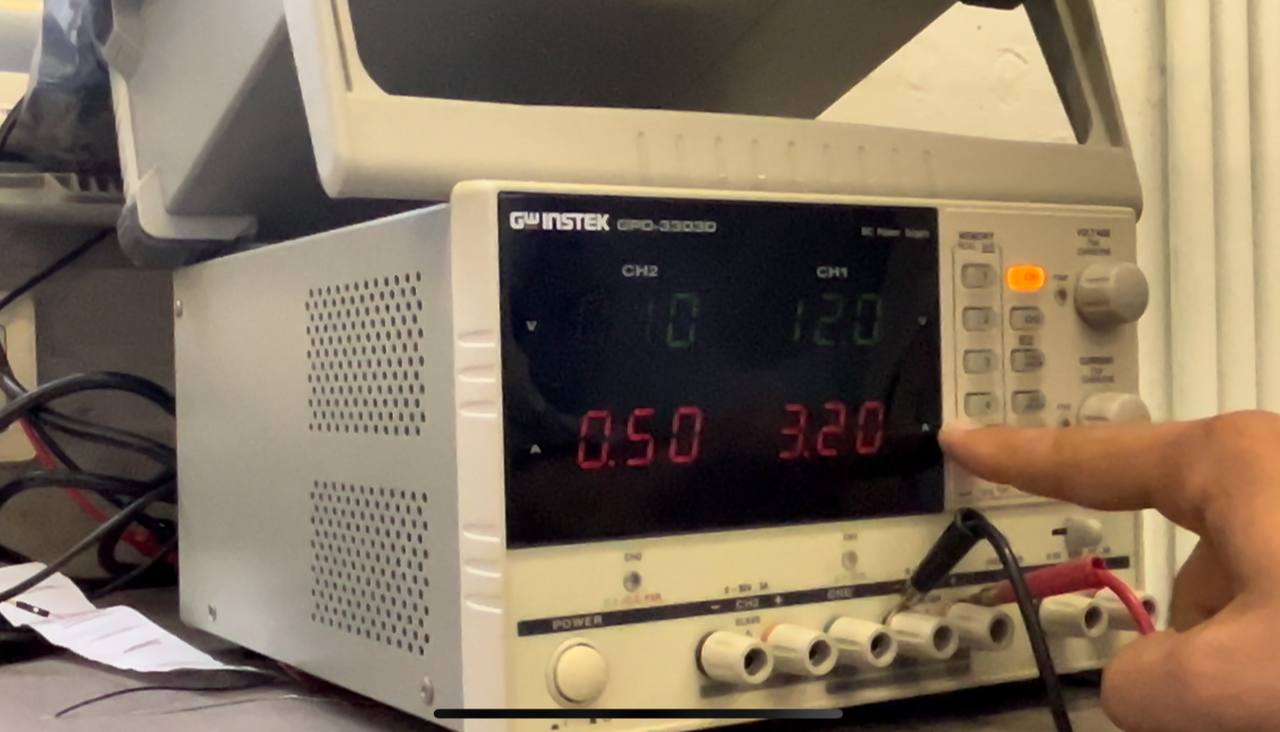
The motor started to rotate.
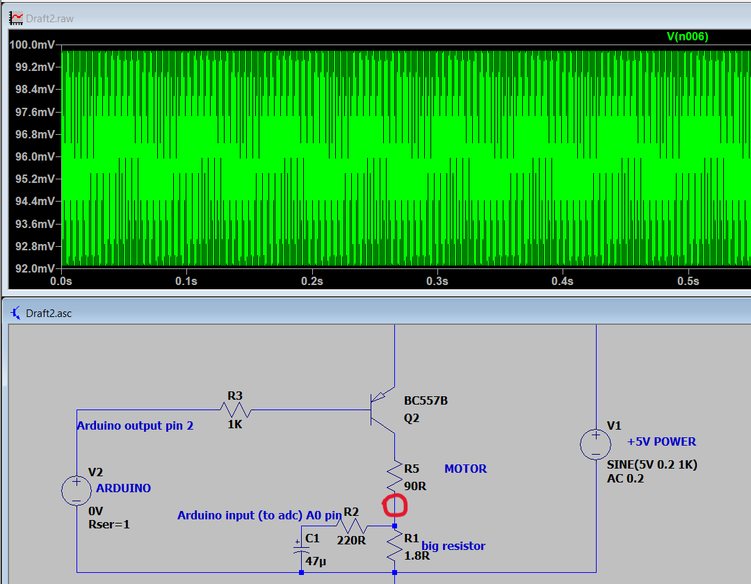
After that Onik decided to show us the creation of an electrical circuit for measuring the current. We used LTspice software. Here is the schematic we used.

We had a power source V1 that provides 5V, and it can be the range of 4.8V to 5.2 V. The power source has 1KHz frequency. We replaced the DC motor with a resistor R of 90 Ohms. For control the motor we added a pnp transistor that marked Q2. V2 is the output pin of Arduino board. If the Arduino pin is HIGH,the current can flow through it the pnp transistor and if it is LOW current current can flow through the pnp transistor. After that we connected R1 resistor(1.8 Ohms) in series with the motor to provide the voltage drop in this part. We also connected R2 resistor(220 Ohms) in parallel with R1, to which C1 capacitor (47 mF) is connected in series for voltage stabilization.
When it was ready we saw the graph in LTspice It measured the value between R5 and R1 .
After that we built a circuit in real.

Individual assignment
The assignment for this week was to add an output device to a microcontroller board I’ve designed,and program it to do something.
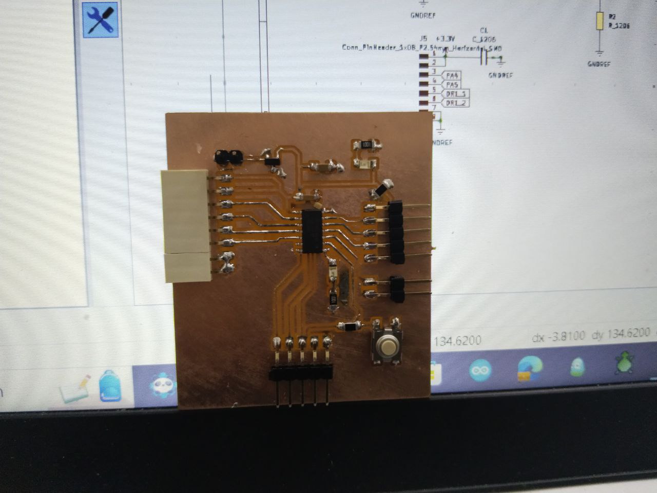
I changed my board design a little bit and added pinheaders that I can use for my output devices.

But as I found out, there are still gaps in the PCB I designed, which I did not foresee before applying it.
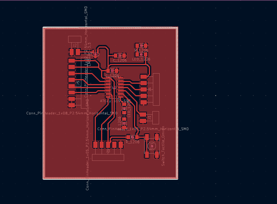
There was only 1 5V pin, but when connecting the OUTPUT devices I realized it would be nice to have an extra 5V pin․That’s why I used a breadboard when connecting the devices. Also, when I wanted to connect the LCD screen, I realized that I connected the SDA and SCL pins of the Attiny 1614 microcontroller to the LED and the button on the board.

But thanks to this bug, I learned how to programmatically make each pin SCL or SDA․ This is my current PCB.
Output devices programming
At first I chose to program a Servo motor. Because I used it before connections and the program turned out to be quite easy.The only problem was the lack of a 5V pin, but I used a breadboard.
Servo motor connections and programming
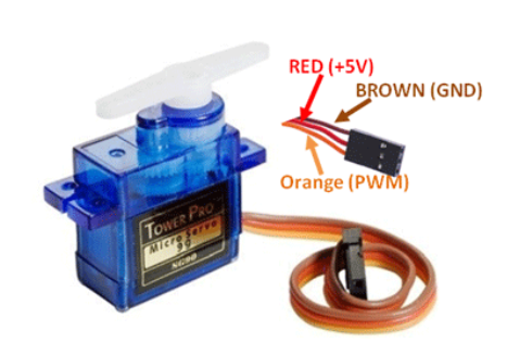
I had programmed the Servo motor by importing the library into the program, this time I decided to try both versions, with and without the library. I used Servo TowerPro SG-90 and here are features
| Property | Value |
|---|---|
| Operating Voltage | +5V |
| Torque | 2.5kg/cm |
| Operating speed | 0.1s/60° |
| Gear Type | Plastic |
| Rotation | 0°-180° |
Servo motor programming with library
# <Servo.h>
# define motorPin 0
int delayTime=500;
Servo motor;
void setup() {
 motor.attach(motorPin);

}

void loop() {
  motor.write(0);
  delay(delayTime);
  motor.write(90);
  delay(delayTime);
  motor.write(180);
  delay(delayTime);
}
define is a useful C++ component that allows the programmer to give a name to a constant value before the program is compiled. Defined constants in arduino don’t take up any program memory space on the chip. The compiler will replace references to these constants with the defined value at compile time.
Servo.h is library that is allows boards to control a variety of servo motors.
-
Servo is class name in the library.
-
motor is the name of the class object.
-
write() and attach() are the methods from the library.
-
attach(pin)- pin the number of the pin that the servo is attached to
-
write(angle) -angle: the value to write to the servo, from 0 to 180
The second code with the Servo.h library tha I tried was with for loop. It allowed to rotate the motor from 0 degrees to 180 degrees and vice versa
# include <Servo.h>
# define motorPin 0
int delayTime=15;
Servo motor;
void setup() {
 motor.attach(motorPin);

}

void loop() {
 for(int i =0; i<=180;i++){
  motor.write(i);
  delay(delayTime);
 }
 for(int i=180;i>=0;i--){
  motor.write(i);
  delay(delayTime);
 }
}
first for loop
initialization: to 0
condition: smaller than or equal to 180
increment: by 1
second for loop
initialization: to 180
condition: greater than or equal to 0
decrement: by 1
Servo motor programming without library
After that I tried to realize how can I write code for Servo motor without library. First I need to find pulse width range. I find different ranges. But approximately the values ranged from 500 to 2400 (microseconds)․ Here is the code with explanation. To avoid code repetition, I used a function and named moveServo.
// Define the pin connected to the servo
const int servoPin = 0;

void setup() {
  // Initialize the servo pin as an output
  pinMode(servoPin, OUTPUT);
}

void loop() {
  // Sweep the servo from 0 to 180 degrees
  for (int angle = 0; angle <= 180; angle++) {
    moveServo(angle);
    delay(15); // Adjust the delay for smoother motion
  }

  // Sweep the servo from 180 to 0 degrees
  for (int angle = 180; angle >= 0; angle--) {
    moveServo(angle);
    delay(15); // Adjust the delay for smoother motion
  }
}

// Function to move the servo to a specific angle
void moveServo(int angle) {
  // Adjust these values based on your servo's specifications
  const int minPulseWidth = 500; // Minimum pulse width in microseconds
  const int maxPulseWidth = 2400; // Maximum pulse width in microseconds
  // Convert the desired angle to a pulse width between the minimum and maximum values
  int pulseWidth = map(angle, 0, 180, minPulseWidth, maxPulseWidth);

  // Send the PWM signal to the servo
  digitalWrite(servoPin, HIGH);
  delayMicroseconds(pulseWidth);
  digitalWrite(servoPin, LOW);

  // Wait for the servo to reach the desired position
  delay(20);
}
RBG led connection and programming
A white light produce by mixing 3 different colors like RGB- Red, Green, and Blue is an RGB LED.
RGB LEDs are 2 types common cathode and common anode.

The programming of that’s 2 types is different.
Here are code examples of RGB led with setColor function. Common Cathode
int redPin= 11;
int greenPin = 10;
int bluePin = 9;

void setup() {
  pinMode(redPin, OUTPUT);
  pinMode(greenPin, OUTPUT);
  pinMode(bluePin, OUTPUT);
}

void loop() {
  setColor(255, 0, 0); // Red Color
  delay(1000);

  setColor(0, 255, 0); // Green Color
  delay(1000);

  setColor(0, 0, 255); // Blue Color
  delay(1000);

  setColor(255, 255, 0); // Yellow Color
  delay(1000);

  setColor(0, 255, 255); // Cyan Color
  delay(1000);

  setColor(255, 0, 255); // Magenta Color
  delay(1000);

  setColor(255, 165, 0); // Orange Color
  delay(1000);

  setColor(128, 0, 128); // Purple Color
  delay(1000);

  setColor(255, 255, 255); // White Color
  delay(1000);
}

void setColor(int redValue, int greenValue, int blueValue) {
  analogWrite(redPin, redValue);
  analogWrite(greenPin, greenValue);
  analogWrite(bluePin, blueValue);
}
Common Anode If we are using a common anode RGB LED, the logic is inverted compared to a common cathode RGB LED. In a common cathode RGB LED, you provide power (HIGH) to a specific pin to turn on a color. For a common anode RGB LED, you ground (LOW) a specific pin to turn on a color.
int redPin= 11;
int greenPin = 10;
int bluePin = 9;

void setup() {
  pinMode(redPin, OUTPUT);
  pinMode(greenPin, OUTPUT);
  pinMode(bluePin, OUTPUT);
}

void loop() {
  setColor(255, 0, 0); // Red Color
  delay(1000);

  setColor(0, 255, 0); // Green Color
  delay(1000);

  setColor(0, 0, 255); // Blue Color
  delay(1000);

  setColor(255, 255, 0); // Yellow Color
  delay(1000);

  setColor(0, 255, 255); // Cyan Color
  delay(1000);

  setColor(255, 0, 255); // Magenta Color
  delay(1000);

  setColor(255, 165, 0); // Orange Color
  delay(1000);

  setColor(128, 0, 128); // Purple Color
  delay(1000);

  setColor(255, 255, 255); // White Color
  delay(1000);
}

void setColor(int redValue, int greenValue, int blueValue) {
  analogWrite(redPin, 255 - redValue);
  analogWrite(greenPin, 255 - greenValue);
  analogWrite(bluePin, 255 - blueValue);
}
After that I decided to connect RGB led with and without potentiometer. I generated code with ChatGPT 3.5 and tried understand. I had RGB led with common cathode.
const int redPin = 0;
const int greenPin = 1;
const int bluePin = 10;
const int potPin = 2;
int currentColorValueRed;
int currentColorValueGreen;
int currentColorValueBlue;
void setup()
{
    pinMode(redPin, OUTPUT);
    pinMode(greenPin, OUTPUT);
    pinMode(bluePin, OUTPUT);
}

void loop()
{

    int potPinValue = map(analogRead(potPin), 0, 1023, 0, 255);

    if (potPinValue <= 42.5) {
        currentColorValueRed = 255;
        currentColorValueGreen = potPinValue * 6;
        currentColorValueBlue = 0;
   }

   if ((potPinValue > 42.5) && (potPinValue <= 85)) {
        currentColorValueRed = 255 - (potPinValue - 43) * 6;
        currentColorValueGreen = 255;
        currentColorValueBlue = 0;
   }

   if ((potPinValue > 85) && (potPinValue <= 127.5)) {
        currentColorValueRed = 0;
        currentColorValueGreen = 255;
        currentColorValueBlue = (potPinValue - 85) * 6;
   }

    if ((potPinValue > 127.5) && (potPinValue <= 170)) {
        currentColorValueRed = 0;
        currentColorValueGreen = 255 - (potPinValue - 127.5) * 6;
        currentColorValueBlue = 255;
    }

    if ((potPinValue > 170) && (potPinValue <= 212.5)) {
        currentColorValueRed = (potPinValue - 170) * 6;
        currentColorValueGreen = 0;
        currentColorValueBlue = 255;
    }

    if ((potPinValue > 212.5) && (potPinValue <= 255)) {
        currentColorValueRed = 255;
        currentColorValueGreen = 0;
        currentColorValueBlue = 255 - (potPinValue - 212.5) * 6;
    }

    analogWrite(redPin, currentColorValueRed);
    analogWrite(bluePin, currentColorValueBlue);
    analogWrite(greenPin, currentColorValueGreen);
}
This code was a little bit difficult to understand especially this part.
currentColorValueRed = (potPinValue - 170) * 6;
Here is the explanation of Chat GPT 3.5.
In the line currentColorValueRed = (potPinValue - 170) * 6 you are calculating the value for the red component of the RGB LED based on the position of the potentiometer. Let’s break down this line:
potPinValue: This variable holds the current value read from the potentiometer, which has been mapped to a range from 0 to 255.
(potPinValue - 170): This calculates the difference between the current potentiometer value and 170. This operation shifts the reference point for the potentiometer value, essentially adjusting where the transition between colors occurs.
(*6): This multiplier scales the difference obtained in step 2. By multiplying by 6, you are determining how quickly the red component changes as the potentiometer is adjusted. Increasing this multiplier would make the red component change more rapidly, while decreasing it would slow down the rate of change.
Overall, this line of code is adjusting the intensity of the red component of the RGB LED based on the position of the potentiometer, with the rate of change determined by the multiplier.
After that I tried to write code that was more easy to understand. First version
# define RedPin 0
# define BluePin 10
# define GreenPin 1
# define PotPin 2

void digitalWriteRGB(byte red, byte blue, byte green)
{
  digitalWrite(RedPin, red);
  digitalWrite(BluePin, blue);
  digitalWrite(GreenPin, green);
}

void setup()
{
  pinMode(RedPin, OUTPUT);
  pinMode(BluePin, OUTPUT);
  pinMode(GreenPin, OUTPUT);
}

void loop()
{
  int potentiometerValue = analogRead(PotPin);
  int mode = map(potentiometerValue, 0, 1023, 0, 6);

  switch (mode) {
    case 0:
      digitalWriteRGB(HIGH, LOW, LOW);
      break;
    case 1:
      digitalWriteRGB(LOW, HIGH, LOW);
      break;
    case 2:
      digitalWriteRGB(LOW, LOW, HIGH);
      break;
    case 3:
      digitalWriteRGB(HIGH, HIGH, LOW);
      break;
    case 4:
      digitalWriteRGB(HIGH, LOW, HIGH);
      break;
    case 5:
      digitalWriteRGB(LOW, HIGH, HIGH);
      break;
    case 6:
      digitalWriteRGB(HIGH, HIGH, HIGH);
      break;
    default:
      digitalWriteRGB(LOW, LOW, LOW);
      break;
  }
}
I changed a little bit code and used analogWrite() function to control the brightness of each color component (red, green, blue) of the RGB LED instead of just turning them on or off with digitalWrite().
# define RedPin 0
# define BluePin 10
# define GreenPin 1
# define PotPin 2

void analogWriteRGB(byte red, byte blue, byte green)
{
  analogWrite(RedPin, red);
  analogWrite(BluePin, blue);
  analogWrite(GreenPin, green);
}

void setup()
{
  pinMode(RedPin, OUTPUT);
  pinMode(BluePin, OUTPUT);
  pinMode(GreenPin, OUTPUT);
}

void loop()
{
  int potentiometerValue = analogRead(PotPin);
  int value = map(potentiometerValue, 0, 1023, 0, 255);

  analogWriteRGB(value, 0, 0); // Red
  delay(1000);
  analogWriteRGB(0, value, 0); // Green
  delay(1000);
  analogWriteRGB(0, 0, value); // Blue
  delay(1000);
}
Active and passive buzzers programming
Then I connected active and passive buzzers to my board. An active buzzer always plays the same tone. A passive buzzer can play a variety of tones. It requires a connection to be made and a specific signal to play the chosen tone. Active buzzer simple code.
// Define the pin to which the buzzer is connected
int buzzerPin = 0;
void setup() {
  // Set the buzzer pin as an output
  pinMode(buzzerPin, OUTPUT);
}

void loop() {
  // Turn on the buzzer by setting the pin HIGH
  digitalWrite(buzzerPin, HIGH);
  // Wait for 500 milliseconds (0.5 seconds)
  delay(500);
  // Turn off the buzzer by setting the pin LOW
  digitalWrite(buzzerPin, LOW);
  // Wait for another 500 milliseconds
  delay(500);
}
After that I searched code Happy Birthday song with passive buzzer.
int speakerPin = 0; // Buzzer pin
int length = 28; // the number of  notes
char notes[] = "GGAGcB GGAGdc GGxecBA yyecdc";
int beats[] = {2,2,8,8,8,16,1,2,2,8,8,8,16,1,2,2,8,8,8,8,16,1,2,2,8,8,8,16};
int  tempo = 200;// time delay between notes

void playTone(int tone, int duration)  {
for (long i = 0; i < duration * 1000L; i += tone * 2) {
   digitalWrite(speakerPin,  HIGH);
   delayMicroseconds(tone);
   digitalWrite(speakerPin, LOW);
   delayMicroseconds(tone);
}
}

void  playNote(char note, int duration) {
char names[] = {'C', 'D', 'E', 'F', 'G',  'A', 'B',

                 'c', 'd', 'e', 'f', 'g', 'a', 'b',

                 'x', 'y' };

int tones[] = { 1915, 1700, 1519, 1432, 1275,  1136, 1014,

                 956,  834,  765,  593,  468,  346,  224,

                 655 , 715 };

int SPEE = 5;

// play the tone corresponding  to the note name

for (int i = 0; i < 17; i++) {

   if (names[i] ==  note) {
    int newduration = duration/SPEE;
     playTone(tones[i], newduration);
   }
}
}

void setup() {
pinMode(speakerPin, OUTPUT);
}

void  loop() {
for (int i = 0; i < length; i++) {
   if (notes[i] == ' ') {
     delay(beats[i] * tempo); // delay between notes
   } else {
     playNote(notes[i],  beats[i] * tempo);
   }
   // time delay between notes
   delay(tempo);
}
}
I2C LCD display programming
Because I accident connected SMD button and led to my board in SCL(pin 7) and SDA(pin 6). I tried to solve this problem and started to search solution. I found out that I couldn’t solve this in hardware level but I could do it in software level.I read it Arduino forum page and decided to try. Arduino forum SDA and SCL pins changing. It worked. And I wrote code for LCD screen. In this example I set two digital pins as SCL and SDA pins.
# include <SoftwareWire.h>
const int sda=0, scl=1;
SoftwareWire Wire(sda,scl);
# <hd44780.h>
# include <hd44780ioClass/hd44780_I2Cexp.h>
hd44780_I2Cexp lcd; // declare lcd object and let it auto-configure everything.

void setup()
{
int istatus;

  istatus = lcd.begin(16,2);
  if(istatus)
  {
 // LCD initalization failed.
 // handle it anyway you want
 if(istatus < 0)
 istatus = -istatus;
 lcd.fatalError(istatus); // blinks error if LED_BUILTIN is defined
  }
  lcd.print("Finally works!");
}

When I searched solution for changing SDA and SCL pins I thought about multiple I2C connections and became interesting how could I connect them if they have the same address I found interesting article.
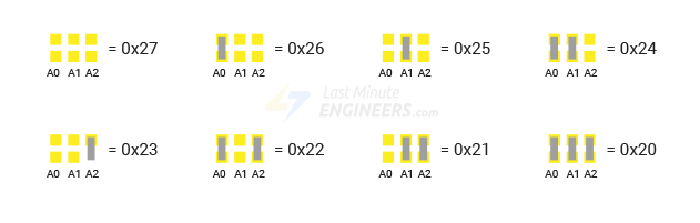
If we have multiple devices on the same I2C bus, we may need to set a different I2C address for the LCD adapter to avoid conflicting with another I2C device. For this purpose, the adapter comes with three solder jumpers/pads (A0, A1, and A2). The address is set when a jumper is shorted with a blob of solder.
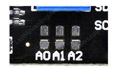
THe default I2C address of LCD display is 0x27.
When we short a solder jumper, we pull that address input LOW. If we were to short all three jumpers, the address would be 0x20. So the range of all possible addresses spans from 0x20 to 0x27. We can set a different I2C address, according to the table below.
Conclusion
This week was very interesting, because I again design new board, it was my second time and was easier then my first time, but after making the board I understood that I put just 1 pin vor 5V, but I need more because most of output devices that I wanted to use are working with 5V. That’s why I have to use breadboard. And I also used my I2C pins and connected button and led to them, but I learned due to this mistake how make any digital pin to SCL and SDA pin with programming. And additionally I learned also how can I change the default I2C address of device.