Week 12- Input devices
Group Assignment:
- Probe an input device(s), analog and digital signals
- Document your work to the group work page and reflect on your individual page what you have learned

MEASUREMENT WITH THE OSCILLOSCOPE
Firstly, here is a little information about an oscilloscope!!

An oscilloscope is a device used to visualize electrical signals. It converts these signals into visible waveforms, which are displayed on a screen. The oscilloscope consists of several components, including signal input probes, signal conditioning systems, vertical and horizontal.
We were instructed to use test instruments (multimeters, oscilloscopes, etc.) to observe the signal that a sensor was producing for this weeks group task. We made the decision to test an ultrasound sensor and use an oscilloscope to view the signal.
SO lets begin by writing the arduino code in Arduino IDE!!!
Here is the code we used:
                const int pingPin = 7; // Trigger Pin of Ultrasonic Sensor
                const int echoPin = 6; // Echo Pin of Ultrasonic Sensor


                void setup() {
                     Serial.begin(9600); // Starting Serial Terminal
                }
                void loop() {
                     long duration, inches, cm;
                     long duration, inches, cm;
                     pinMode(pingPin, OUTPUT);
                     digitalWrite(pingPin, LOW);
                     delayMicroseconds(2);
                     digitalWrite(pingPin, HIGH);
                     delayMicroseconds(10);
                     digitalWrite(pingPin, LOW);
                     pinMode(echoPin, INPUT);
                     duration = pulseIn(echoPin, HIGH);
                     inches = microsecondsToInches(duration);
                     cm = microsecondsToCentimeters(duration);
                     Serial.print(inches);
                     Serial.print("in, ");
                     Serial.print(cm);
                     Serial.print("cm");
                     Serial.println();

                     delay(100);
                }
Connections
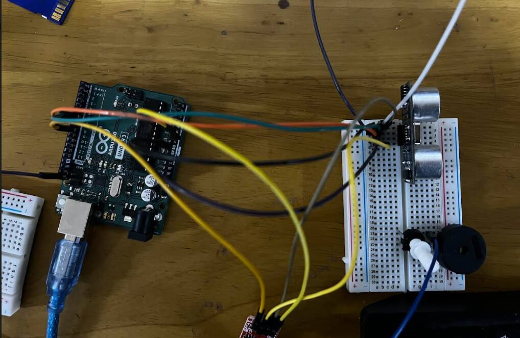
Here is we connected our pins:
- Echo - Digital pin 6
- Trig - Digital pin 7
- Gnd - Gnd
- Vcc - Vcc
Now connect it to the oscilloscope whereby probes are connected to Gnd and Echo pins!!

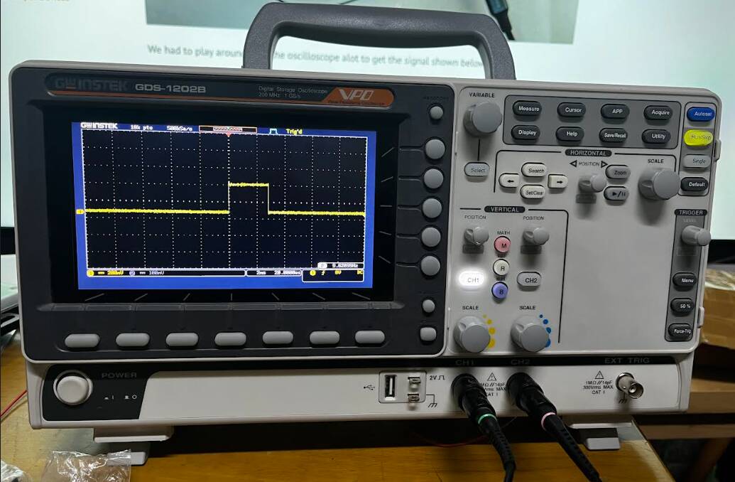
So after a few tries of displaying the signal, here is how it looks:

And this is how it looks in the serial monitor!

Here is a video of us tesing the ultrasonic sensor to show the signals!!
Sound sensor

A sound sensor is a device that converts sound waves into an electrical signal that can be processed by an electronic circuit. They can be used to detect and measure the amplitude, frequency, and duration of sound waves. It has both analouge and digital output pins. We decided to check the analogue signal!
Setting up

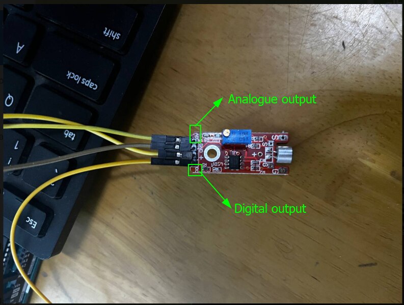
Here is the connection we made:

Now for the code, we decided to use the analogue serial example code. To find it go to files -> examples -> Analogue -> AnalogueInOutSerial -> then change the pins according to your connections.
Here is the code:
// These constants won't change. They're used to give names to the pins used:
            const int analogInPin = A0;  // Analog input pin that the potentiometer is attached to
            const int analogOutPin = 9; // Analog output pin that the LED is attached to

            int sensorValue = 0;        // value read from the pot
            int outputValue = 0;        // value output to the PWM (analog out)

            void setup() {
            // initialize serial communications at 9600 bps:
            Serial.begin(9600);
            }

            void loop() {
            // read the analog in value:
            sensorValue = analogRead(analogInPin);
            // map it to the range of the analog out:
            outputValue = map(sensorValue, 0, 1023, 0, 255);
            // change the analog out value:
            analogWrite(analogOutPin, outputValue);

            // print the results to the Serial Monitor:
            Serial.print("sensor = ");
            Serial.print(sensorValue);
            Serial.print("\t output = ");
            Serial.println(outputValue);

            // wait 2 milliseconds before the next loop for the analog-to-digital
            // converter to settle after the last reading:
            delay(2);
            }
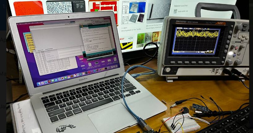
So the sensor does not really detect the sound waves that efficiently so here is how the serial monitor and the oscilloscope display looks like:
THAT'S IT FOR THIS WEEK!!
HAVE A GOOD DAY!