Group Assignment: Week 8

The Oscilloscope
The Oscilloscope is a tool in electronics and electrical engineering that is used for visualizing electrical signals. It provides real-time graphical representation of voltage changes over time, allowing us to analyze and troubleshoot circuits.
What is an Oscilloscope?
An oscilloscope, often referred to as a scope or a CRO (Cathode Ray Oscilloscope), is a device used to observe the waveform of electrical signals. It displays voltage signals on a two-dimensional graph, with the horizontal axis representing time and the vertical axis representing voltage.
How Does it Work?
The basic principle behind how an oscilloscope works is the conversion of electrical signals into visible waveforms, which are displayed on a screen.
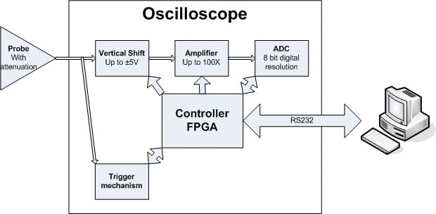
- Signal Input: The oscilloscope is connected to the circuit under test via probes. These probes capture the voltage signal and send it to the oscilloscope.
- Signal Conditioning: The incoming signal may be amplified, attenuated, or adjusted for proper display on the screen. This ensures that the signal remains within the measurable range of the oscilloscope.
- Vertical Deflection: The vertical deflection system adjusts the position of the electron beam on the screen based on the amplitude of the input signal. This creates the vertical axis of the waveform display.
- Horizontal Deflection: The horizontal deflection system moves the electron beam horizontally across the screen at a constant rate, representing time. This creates the horizontal axis of the waveform display. 5.Cathode Ray Tube (CRT) Display: The electron beam strikes a phosphorescent coating on the inside of the CRT, producing light and generating the waveform on the screen.
- Triggering: Triggering synchronizes the display of the waveform with specific events in the input signal, making it easier to analyze repetitive signals or capture specific instances.
Buttons and Functions
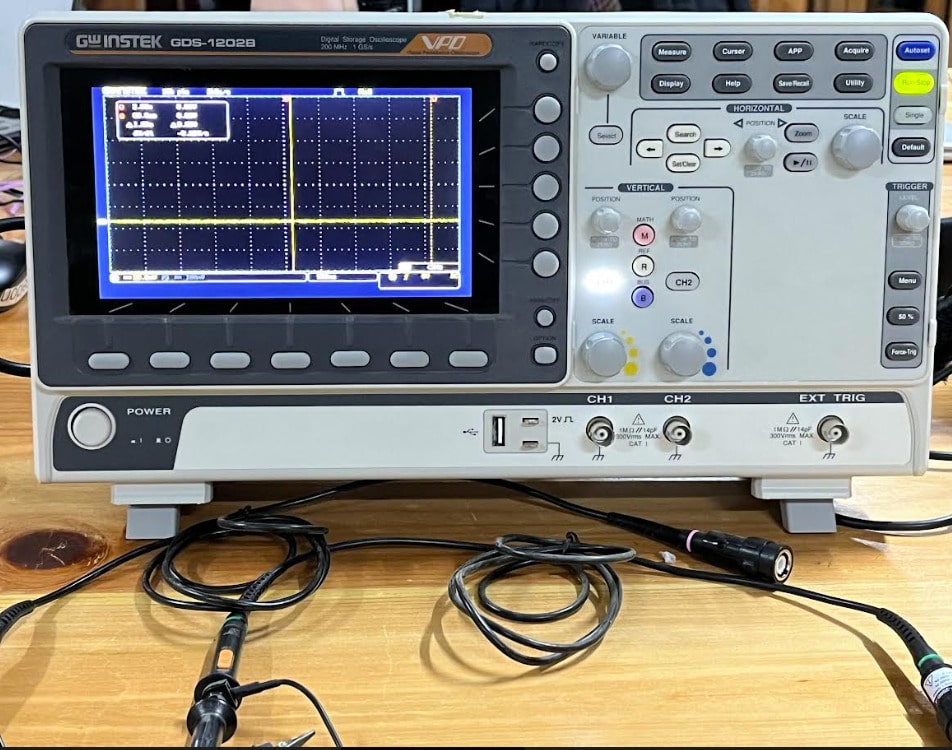
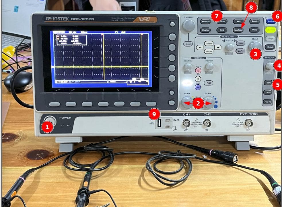
The oscilloscope that we have at our local Fab Lab is the GDS-1202B GW INSTEK. It’s equipped with a lot of buttons and functions to visualize and analyze waveforms. Here are some of the key buttons and their functions:
- Power Button: Turns the oscilloscope on/off.
- Vertical Scale Knobs: Adjusts the vertical scale (volts per division) of the waveform.
- Horizontal Scale Knobs: Adjusts the horizontal scale (time per division) of the waveform.
- Trigger Level Knob: Sets the trigger level for synchronization.
- Trigger Source Button: Selects the input channel for triggering.
- Auto Setup Button: Automatically adjusts the oscilloscope settings for optimal waveform display.
- Cursor Measurement Buttons: Enables measurement of various parameters such as voltage, time, frequency, etc., using on-screen cursors.
- Save/Recall Buttons: Allows saving and recalling of waveform settings and data.
- USB Port: Facilitates data transfer and storage via USB connection.
Connecting to a Microcontroller Board
To better understand the behavior of microcontroller circuits, we connected our oscilloscope to a microcontroller board. This allowed us to visualization signals such as PWM (Pulse Width Modulation) outputs, digital logic levels, and analog sensor readings in real-time 🤯. By observing these signals, we can debug code, optimize our circuit performance, and make sure the functionality of our designs is good.
When connecting the oscilloscope to a microcontroller board, make sure your choose your probes properly, the appropriate signals are grounded, and you adjust your input voltage range to prevent damage to the oscilloscope or the circuit under test. Also make sure to use appropriate triggering settings to capture your signals without issues.
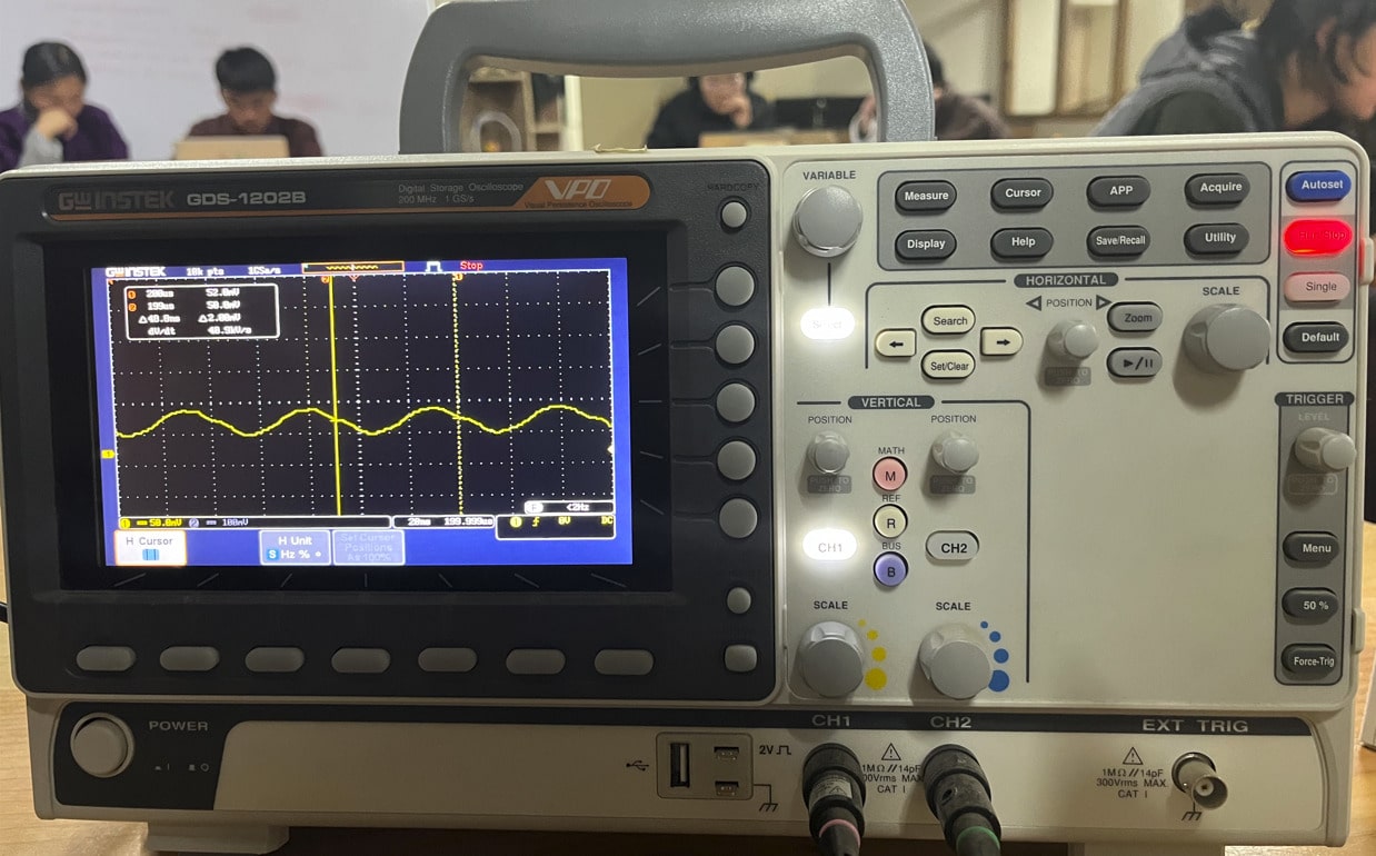
sin waves ;)
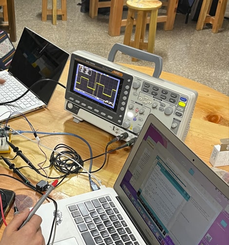
square waves ;0
Using the oscilloscope this week was a pretty eye-opening experience. Watching voltage signals displayed as waveforms on the screen felt like we could actually see the electrical signals flowing. Adjusting the vertical and horizontal scales allowed us to zoom in on details and understand the nuances of signal behavior. Connecting it to a microcontroller board was particularly exciting. We connected it to a motor, and it a us allowed to see the real-time impact of code changes as well as how PMW can affect rotation. Overall, the oscilloscope was really fun to watch and I’ll definitely use it in the future.
The Multimeter
A multimeter, also known as a volt-ohm meter (VOM), is an electronic instrument used to measure various electrical values such as voltage, current, resistance, and continuity. It is an essential tool for anything electrical-related, as well as troubleshooting.
 .jpg)
.jpg)
What is a Multimeter?
A multimeter is a handheld device that combines several measurement functions into a single unit. A multimeter usually consists of a digital or analog display, a selection knob, and input slots for connection probes. Multimeters can measure DC and AC voltage, DC and AC current, resistance, continuity, capacitance, frequency, and sometimes even temperature 🔥.
How Does it Work?
The operation of a multimeter depends on the type of measurement being performed. Here's a general overview of how a multimeter works:
- Voltage Measurement: To measure voltage, the multimeter is connected across the component or circuit under test. The multimeter applies a known resistance (typically very high) across its probes and measures the resulting current flow. Using Ohm's Law (V = IR), it calculates the voltage and displays it on the screen.
- Current Measurement: For current measurement, the multimeter is placed in series with the circuit being measured. It measures the current flowing through the circuit by sensing the voltage drop across a known resistance (the multimeter's internal shunt resistor) and calculates the current using Ohm's Law.
- Resistance Measurement: To measure resistance, the multimeter applies a known voltage across the component under test and measures the resulting current flow. It then calculates the resistance using Ohm's Law (R = V/I) and displays the value on the screen.
- Continuity Test: In continuity testing mode, the multimeter emits an audible beep or displays a visual indication when there is a low resistance (typically below a certain threshold, such as 50 ohms) between the test leads. This mode is used to check for the continuity of wires and connections.
- Other Functions: Depending on the model, multimeters may also offer additional measurement functions such as capacitance measurement, frequency measurement, diode testing, and temperature measurement using specialized probes.
a pretty detailed explanation from circuitbasics
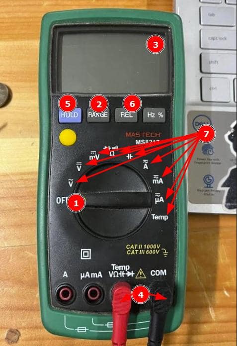
Buttons and Functions (Typical Multimeter)
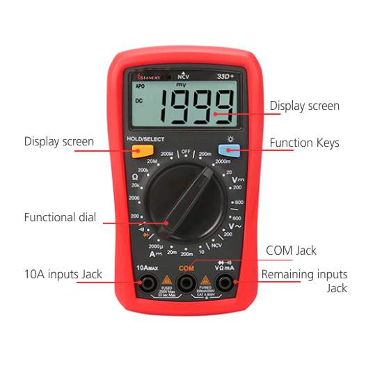
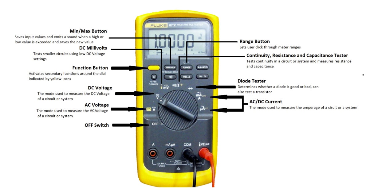
While the specific layout and functionsdiffer from model to model, here are some common buttons and functions found on most multimeters:
- Power/Function Selector Switch: Turns the multimeter on/off and selects the desired measurement function (e.g., voltage, current, resistance, continuity).
- Range Selector Switch: Adjusts the measurement range of the multimeter to accommodate the expected value of the parameter being measured. It can be set to auto-range or manual range mode.
- Display: Shows the measured value and unit of the parameter being measured. It can be either a digital LCD display or an analog needle display.
- Input Jacks: These are the sockets where the test leads or probes are inserted for making measurements. They are usually color-coded (red for positive and black for negative).
- Hold Button: Freezes the display to hold the measured value for easy reading.
- Relative/Zero Button: Allows zeroing out the multimeter's internal resistance or subtracting a reference value from the measurement.
Function Buttons: Some multimeters have dedicated buttons for specific functions like diode testing, capacitance measurement, and temperature measurement.
Connecting to a Circuit
To use a multimeter effectively, proper connection to the circuit under test is crucial. Here are some general guidelines for connecting a multimeter:
- Voltage Measurement: Connect the red probe to the positive (+) terminal and the black probe to the negative (-) terminal of the component or circuit under test.
- Current Measurement: For current measurement, the multimeter must be connected in series with the circuit. Break the circuit and connect the multimeter in-line, ensuring the correct polarity.
- Resistance Measurement: Connect the probes across the component or circuit under test. Ensure that the circuit is de-energized to obtain accurate resistance readings.
- Continuity Test: Place the probes across the circuit or connection being tested. If there is continuity (low resistance), the multimeter will emit an audible beep or display a visual indication.
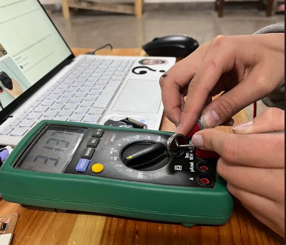
Damzang measuring the voltage of a button cell
Reflection
This weeks group assignment was really fun, and I’m sure all of us learned a lot from it. Hands on experience and spending time with our local instructor really helped us understand how the tools worked, it was also really fun to apply concepts that we learned in class and see that all of it was actually true. Real-time changes on the oscilloscope helped me visualize electrical circuits much better and it really brought me down to earth in respect to circuits, and it reminded me that everything is happening and is calculated, which is pretty important when everything seems like magic sometimes. Experimenting allowed us to develop and refine our troubleshooting skills by diagnosing our circuit issues, verifying component values, and analyzing signal behavior Doing this group assignment with our classmates as well helped us work on collaboration and communication skills as we discussed why something was happening, shared insights, and worked together to come to an actual conclusion that made sense (to us).
Thankyou !!!