Electronics Production-Group Work
Group Assignment for Week 4
Group Assignment:
Characterize the design rules for your in-house PCB production process: document feeds, speeds, plunge rate, depth of cut (traces and outline) and tooling.
Document the workflow for sending a PCB to a board house
Document your work to the group work page and reflect on your individual page what you learned
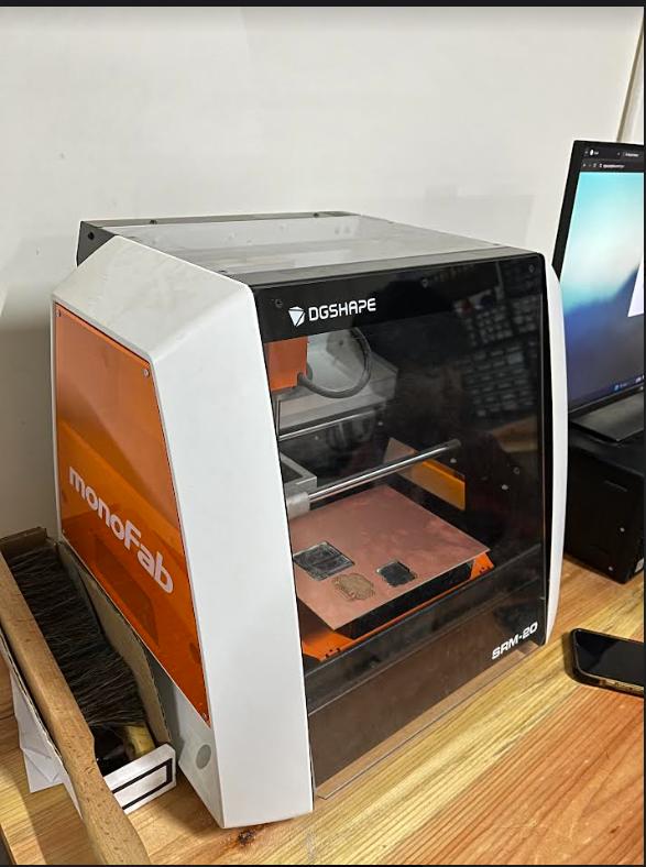
The Monofab SRM-20 Milling Machine
The Monofab SRM-20 Milling Machine is a compact, user-friendly device for precision milling and prototyping applications in various industries.
Click here to learn more about the machine
Machine and Specifications
Cuttable Material: Modelling Wax, Chemical Wood, Foam, Acrylic, Poly acetate, ABS, PC board
X, Y, and Z Operation Strokes: 203.2 (X) x 152.4 (Y) x 60.5 (Z) mm
Distance From Collet Tip to Table : Max, 130.75mm (5.15 in)
Loadable Workpiece Weight : 2 kg (4.4 lb)
X-, Y-, and Z-Axis Drive System : Stepping motor
Operating Speed : 6 - 1800mm/min 0., - 70.87inch/min
Software Resolution : 0.01 mm/step (RML-1), 0.001mm/step (NC code), 0.000039 inches/step (RML-1), 0.000039 inches/step (NC code)
Mechanical Resolution : 0.000998594 mm/step, 0.0000393 inches/step
Spindle Motor : DC motor Type 380
Cutting Tool Chuck : Collet method
Included Items : USB cable, AC adapter, Power cable, Cutting tool, Collet, Set screw, Spanners (7,10mm), Hexagonal wrench (size 2,3 mm), Positioning pins, Double-sided tape, Start-up page guidance card
A detailed specification is given here
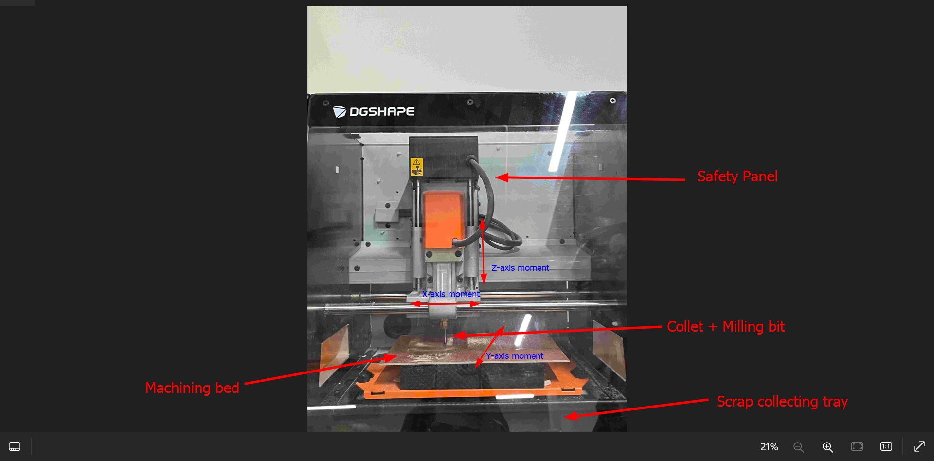
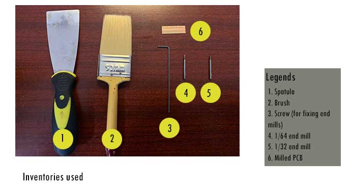
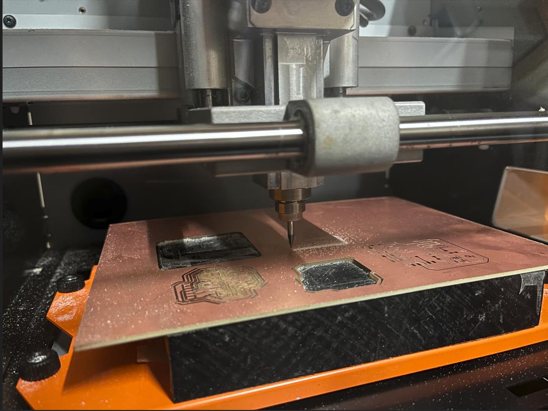
Machine Setup for Milling

Here are the inventories used:
Characterizing Design Rules
To define the rules, we used Neil's characterized file.

Milling Files
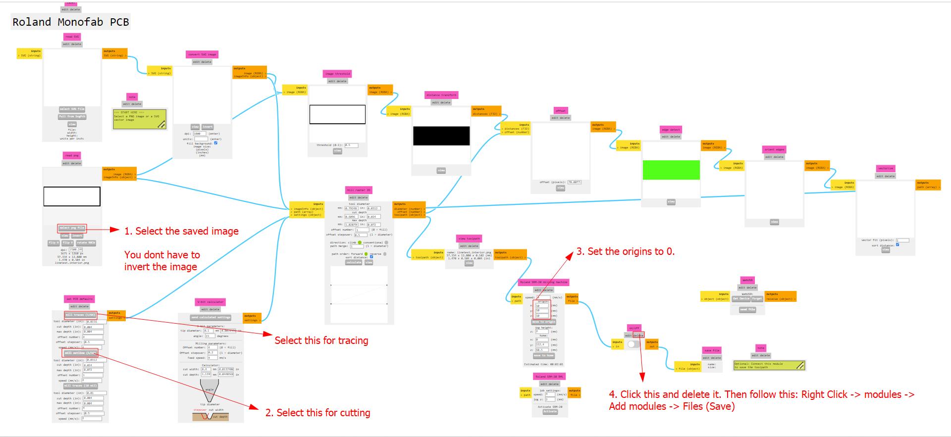
We used MODS to make the cut files in RTL format for our machine.
In Mods right click -> Programs -> Open Program -> Roland (SRM-20 mill 2D PCB)-> Select png
Follow these steps:
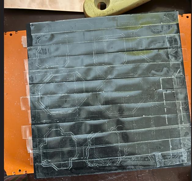
We used double sided tape to stick the board!
Now set the machine and level it
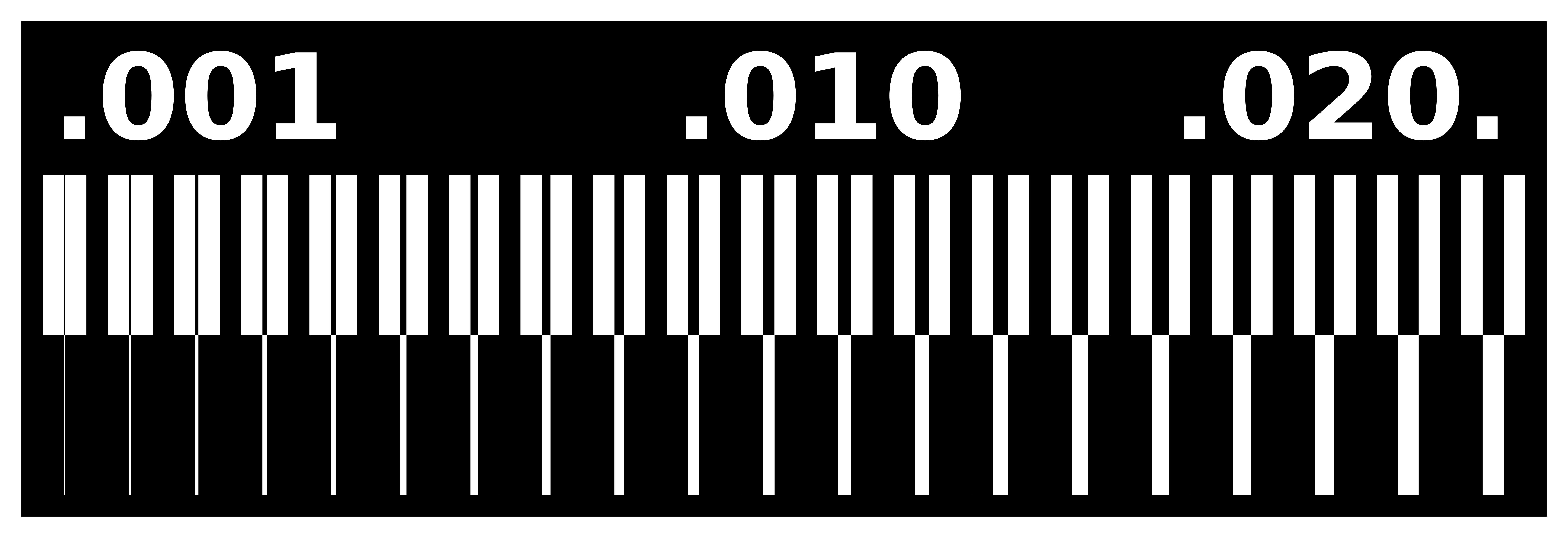
Result

The 1st outcome was not good due to bad block levelling. So we levelled our block properly and did it again.
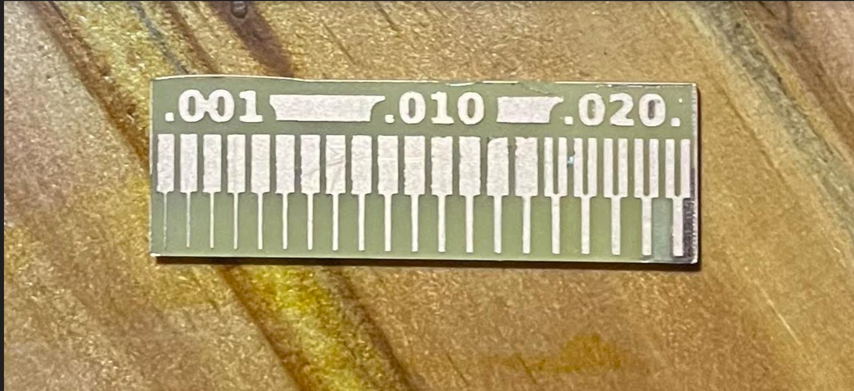
The 2nd outcome was pretty ok and we concluded that only the 0.020 range shows proper visibility of the trace width and spacing. This is due to the fact that the only range larger than 1/64" (0.015) is 0.02. We must therefore stick to this range while designing our circuit boards in the future.
Reflow
Reflow soldering in electronics involves melting pre-applied solder paste to connect components on a circuit board, creating reliable and durable connections during manufacturing.
Here are the materials that we used:
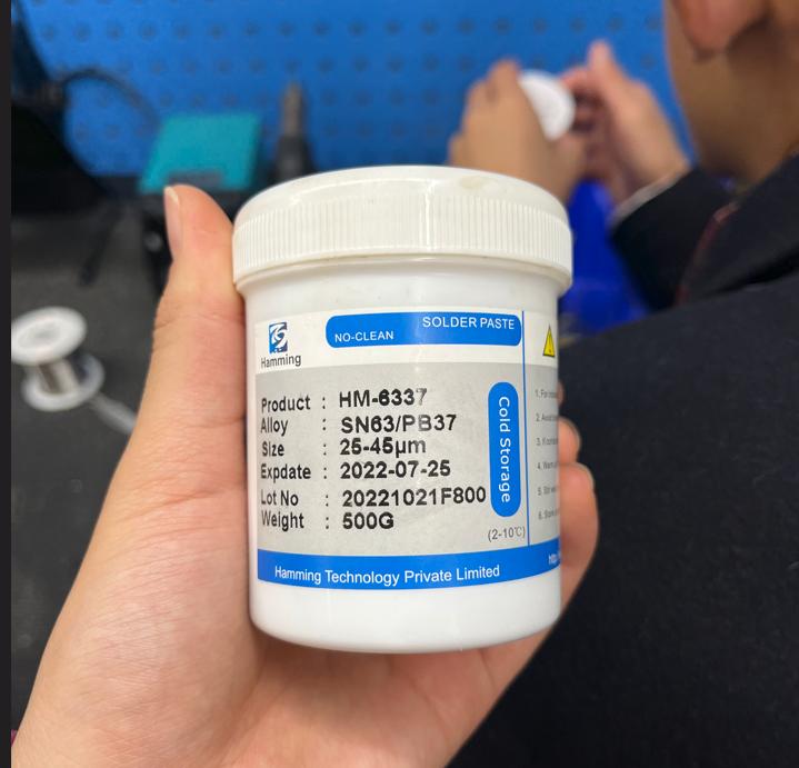
HM 6337 is a soldering paste flux, enhancing solder flow and wetting. It improves electrical connections and is suitable for various soldering applications.
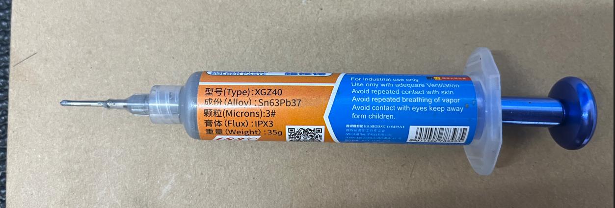
SMD solder paste in syringe form simplifies precise application for surface mount device (SMD) soldering, ensuring accurate and controlled dispensing.
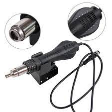
A hot air heat blower in electronics is a tool that uses a stream of heated air to solder, desolder, or rework surface-mounted components on circuit boards.
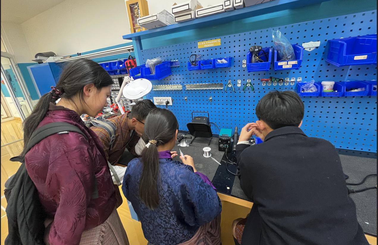
So Mrs. Tshering Wangzom from the JNWSFL, showed us a demo of reflow and here are some images and videos:
Trying it out!
THAT'S IT FOR THIS WEEK!