Machine Design
Assignments
Group assignment:
- Design a machine that includes mechanism + actuation + automation + application
- Build the mechanical parts and operate it manually
- Document the group project
- Actuate and automate your machine
- Document the group project
Individual assignment:
- Document your individual contribution
To do:
- Documented my machine building process to the group page
- Documented my individual contribution to this project on my own website
- Link the group page from my individual page as well as from the group page to my individual pages
- Shown how my team planned, allocated tasks and executed the project (Group page)
- Describe problems and how the team solved them (Group page)
- List possible improvements for this project (Group page)
- Include my design files (Group page)
Learning outcomes
- Work and communicate effectively as a team
- Design, plan and build a machine
- Analyze and solve technical problems
- Recognize opportunities for improvements in the design
Group Assignment
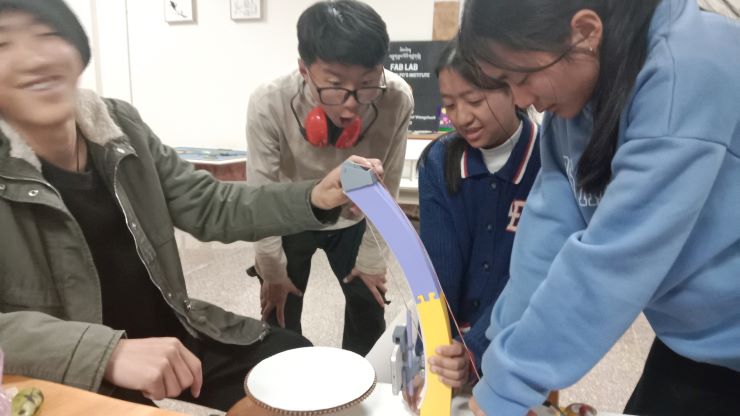
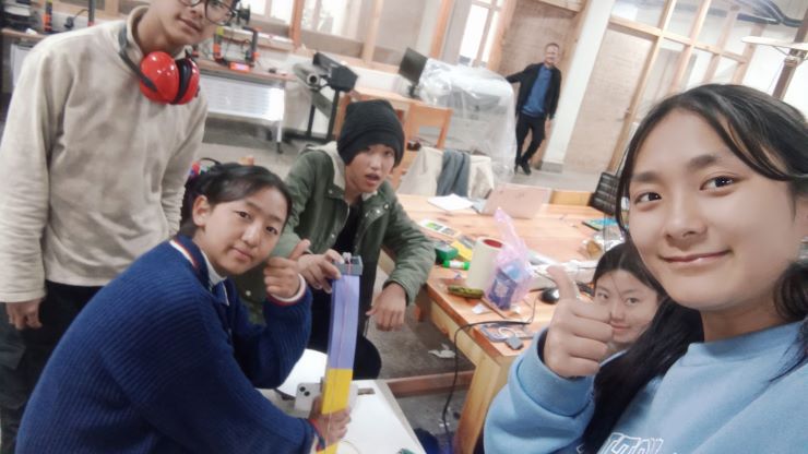
It’s machine design week!!! 😨 We started off by discussing potential ideas for a machine, and we agreed on creating a 3D scanner, since our lab doesn’t have one anymore. We had a group discussion and finally came up with this idea/sketch with the help of our local instructor. We also divided our roles.
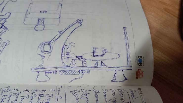
The general idea is a rotating platform (to place your object), and an arm that holds your scanner, and can move the scanner up and down for better results.
Individual Assignment
Yangtshel and Thinley are on design duty and fabrication duty 😨
Fusion360
Fusion360 is a comprehensive CAD/CAM/CAE software developed by Autodesk, suitable for mechanical design and engineering projects. This is the software we’ll be using for most of the 3D designing.
Getting Started If you don't already have an account, you can sign up at this link:
(Once your account is set up, click on "Create" and then select the appropriate workspace for your project.)
If you are unable to download the software (like me at first), what I did was use the browser version.
(Just press LAUNCH and get started)
So we started off by creating the arm, and creating a mechanism for the scanner to move on the z-axis.
Research
Before the actual designing, we did some research on different 3D scanners that were made in the past, and we found quite a few interesting ones. However, one that really stuck out (and one that we referred to religiously) was by Mr. Quentin Bolsée 🙏 After some trial and error, we created this curve, with a slot for our scanner carrier.
https://sketchfab.com/models/4388679db86d434e9d5c57caa8f4b760/embed?ui_theme=dark
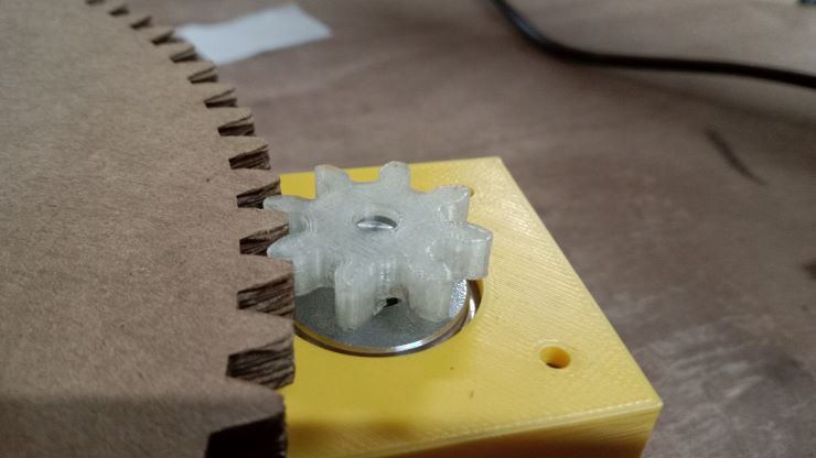
Pulley Head
We decided to use a pulley system to move our scanner, so Thinley started working on that using the arm, and a 16mm bearing as a reference.
Cart
In the meanwhile, Yangtshel fabricated the cart that would move up and down the arm, and consequently move the scanner too.
https://sketchfab.com/models/9e6df6ae2e654cf5a39b344743808e5c/embed
The protrusions are for 16mm bearings, and an included slot to attach to the scanner.
Programming
For the programming part of the machine building, we decided to take over. We tried to program the DC stepper motor to begin with and for this we took reference from this site
These are the steps we followed to program the stepper motor.
1. Connecting Power
- First, we verified and double-checked the correct wiring of our power input (black for ground, red or yellow for +24 volts).
Then we used a DC power supply between 12 and 30 volts capable of providing 4 to 15 amps.
After that we turned on the power supply and checked for correct voltage and polarity before connecting it to TinyG.
2. Setting up Universal Gcode Sender
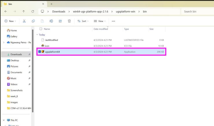
- Now, regarding the software, we downloaded and installed Universal Gcode Sender, a terminal emulator through this site
- Then go to the downloaded folder and then open this file
- We selected the port
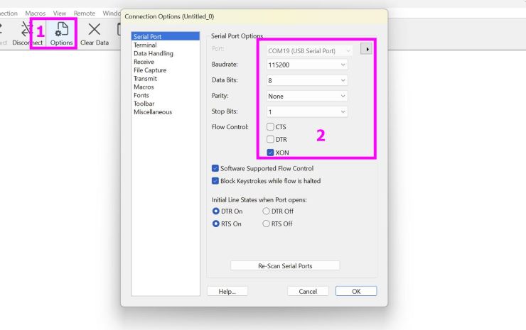
- And connected to TinyG.
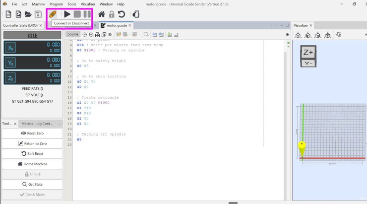
- The content inside the green box indicates a successful connection. Then we identified the coil pairs of our stepper motor using a volt meter.
After that, connected one pair of wires to the A1/A2 terminals and the other pair to the B1/B2 terminals on TinyG's motor outputs.
- We started with the current at zero and gradually increase it until the motor moved smoothly without stalling or running too hot.
Note: Avoid overdriving the motors, which can lead to overheating and damage.
5. Test Drive
Once everything is connected and configured, test drive your stepper motor by sending movement commands through TinyG.
Check for smooth operation, correct direction, and appropriate speed.
For the test drive, we tried with the code that was given in the reference documentation.
We uploaded this code g1 f400 x100
In the above G-Code,
G1: This is a standard G-code command that instructs the machine to move in a straight line from its current position to a specified point at a specified feed rate.F400: This part of the command sets the feed rate or the speed at which the machine should move. The value 400 indicates a feed rate of 400 units per minute. This determines how fast the motor will spin.X100: This part of the command specifies the target position along the X-axis where the machine should move to. In this case, it's instructing the machine to move to the X-coordinate of 100 units.
It worked!!
Next we tried it with a gear that will spin another gear!
For our scanning machine, we are trying to control 2 motors in which the first motor will be used to rotate the platform and the second second motor which will be kept side-down to move the scanning platform of the object vertically.
To control the 2 motors we tried several relevant codes which obviously didn't work in the first iteration but after several tries, the following code worked!!
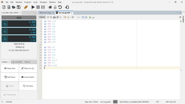
To see how this code worked, see our video for our 3D scanner.
Assembly
Lets now see how we assembled our machine.
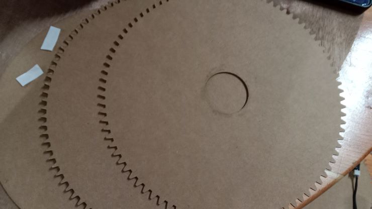
Lets make our gears and adjust them in place.
Now the arm!
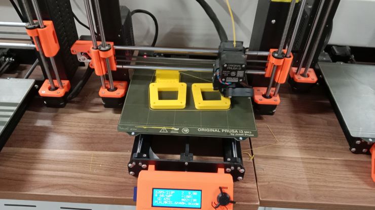
 The wooden arm that we printed didnt come out that good so we decied to 3D print the arm so that it can be smoother.
 Now we started importing all the designs together.