Riichiro Yamamoto
Project Development
Fab Academy 2024
Riichiro Yamamoto
- 1.1 Firmware and Gcode
- 1.2 BabyStepping
- 1.3 Potentiometer + Firmware
- 2.0 DJ 3D Printer
- (Project Review with the Fablab BCN team)
- (4 Weeks until Final Presentation)
- 2.1 - 3.0 Python & MediaPipe & Raspberry Pi
- 3.1 - 4.0 System Intergration
- 4.1 RGB LCD Screen
- 4.2 DJ Coding
- 4.3 Subtractive Manufacturing
- 4.4 Final Adjustment
- 5.0 Presentation
- Project Management
1st Idea
Sketch ideas
Here is an image of my thought process for
realising an idea for my final project.
Firstly, I wrote my pure desire and constructed it in a word.
Secondly, I deconstructed the word by using other explanations.
Thirdly, I reconstructed a sentence using those explanations.
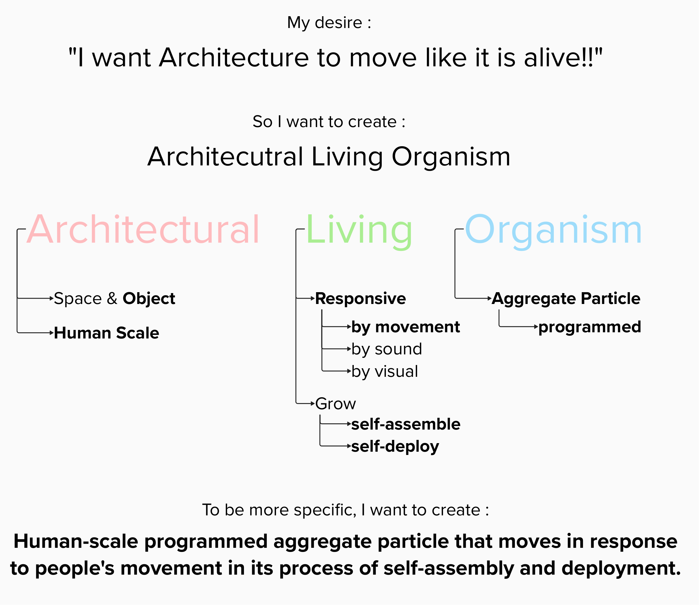
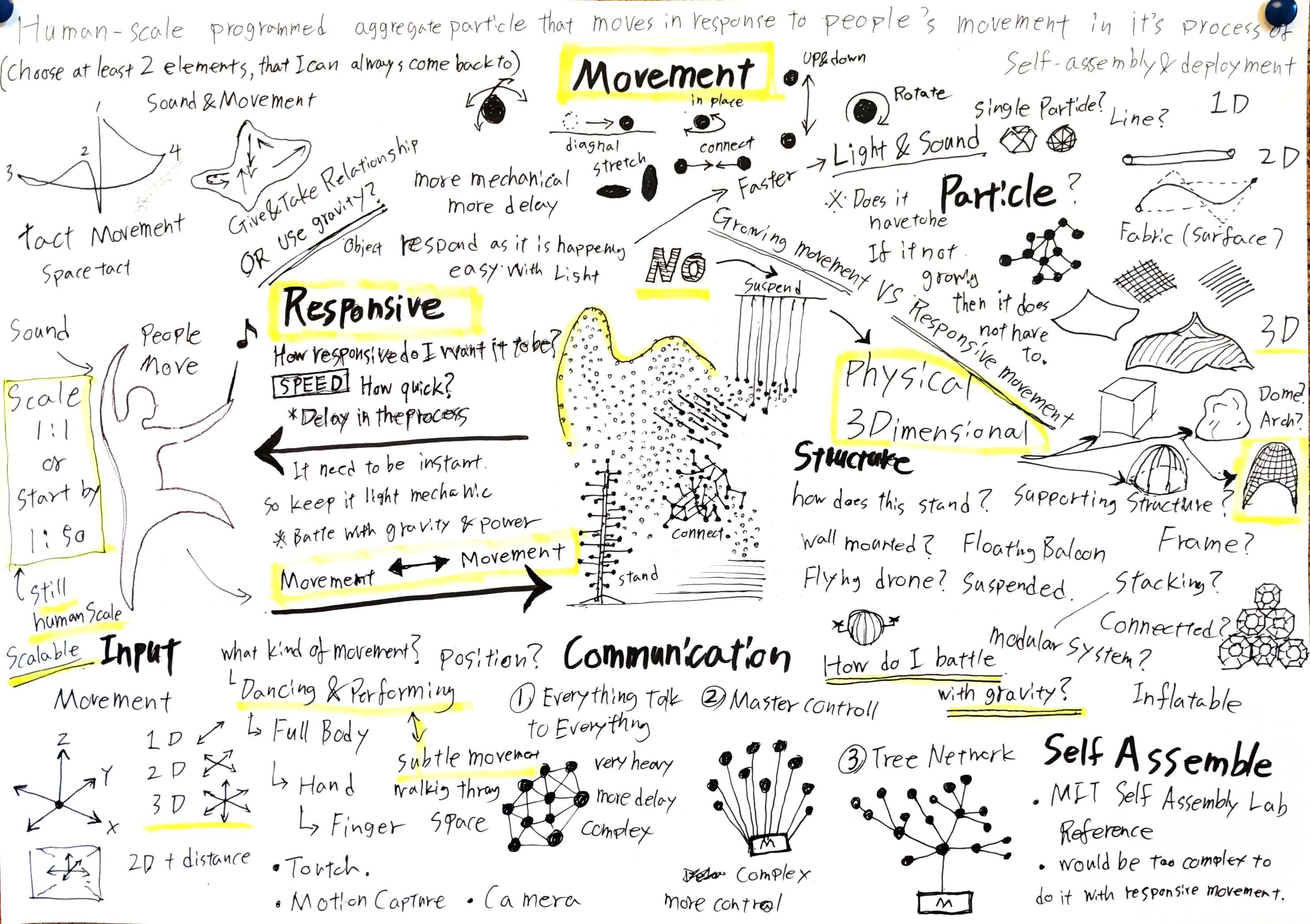
Concept Sketch
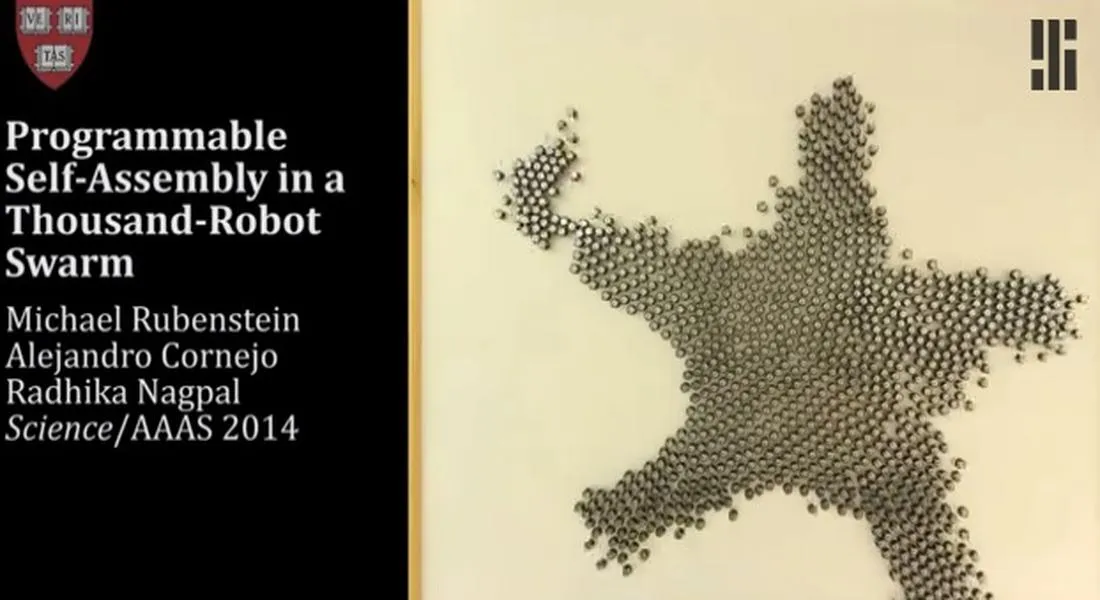
This is a quick sketch showing my interpretation of
Human-scale programmed aggregate particle that moves
in response to people's movement in its process of
self-assembly and deployment.
.jpg)
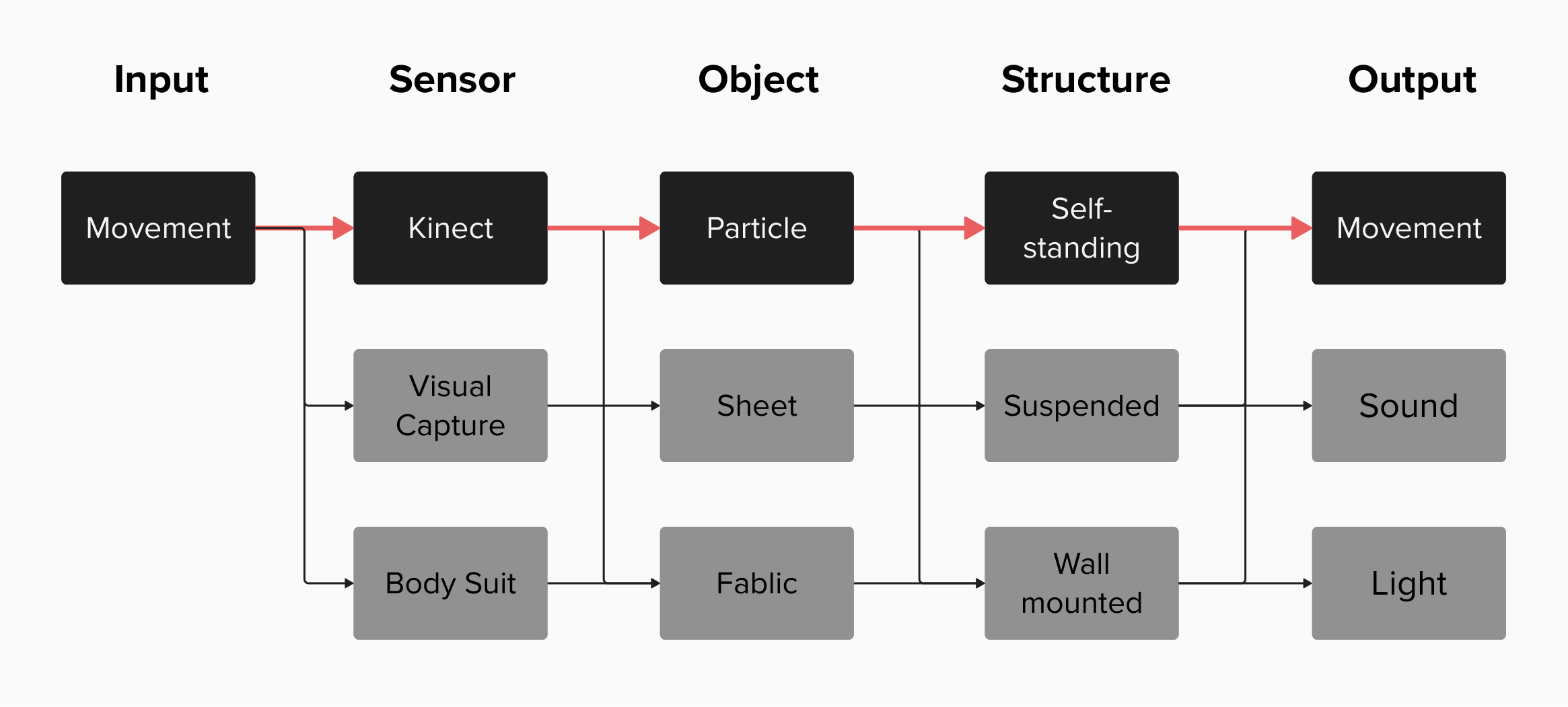
Ideal passway towards the outcome
At this point, my idea for the final project is very idealistic and it has a lack of actuality in the sense of accomplishing with limited time and knowledge within this programme. I thought about other ways and methods that could bring this project together. However, I would like to stick with my ideal passway (red arrow) for now, and I will decide which passway this project should go in the process.
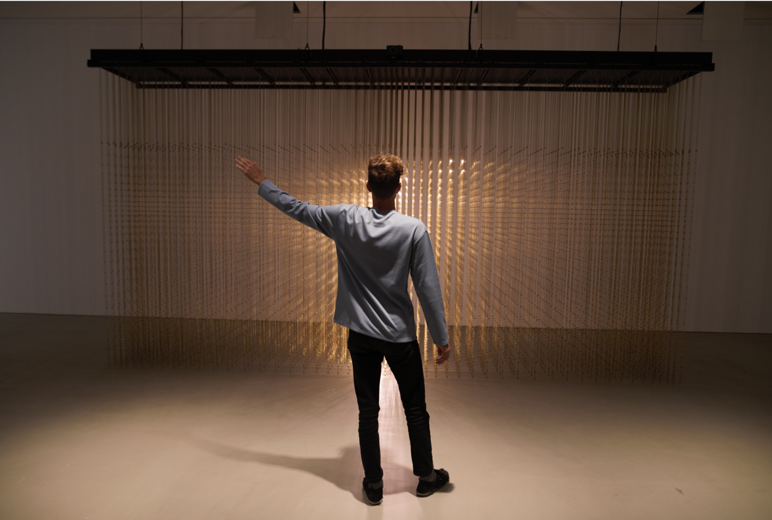
Visual Reference
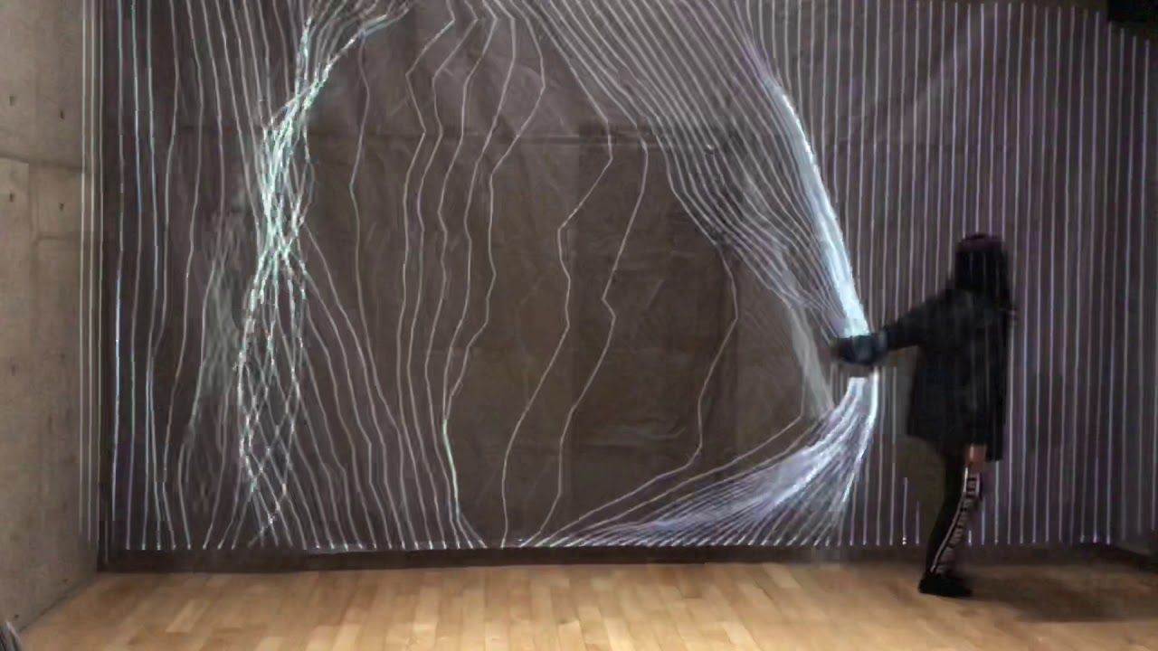
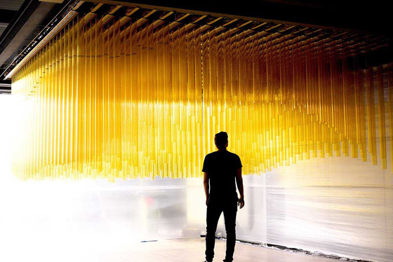
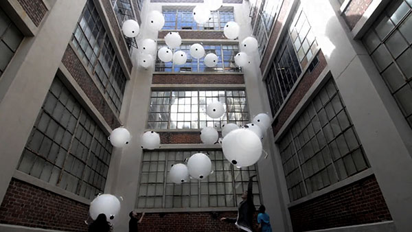
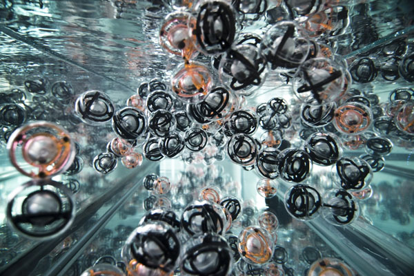
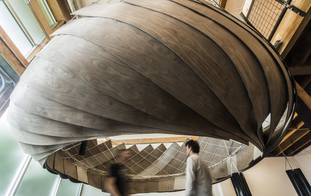
This is a short video of artwork titled "Ghost" by Tobias Gremmler.
I want to create something that looks like this...
"But Physical 3D version"


Reference
Responsive

Self-Assemble

Particles

Kinetic Surface


Structure-Surface


Other

:format(webp)/cdn.vox-cdn.com/uploads/chorus_asset/file/22459839/Screen_Shot_2021_04_21_at_12.30.52_PM.png)

Modelling
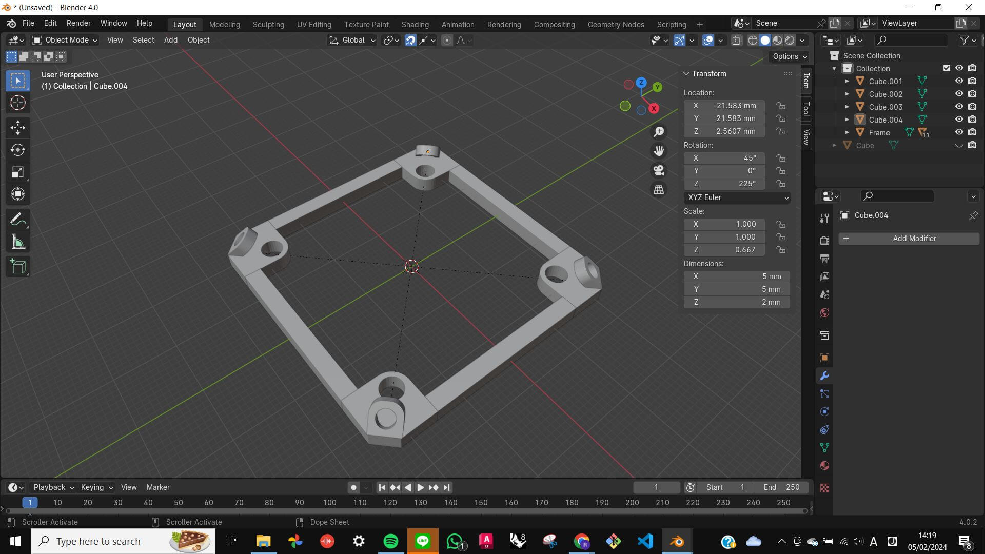
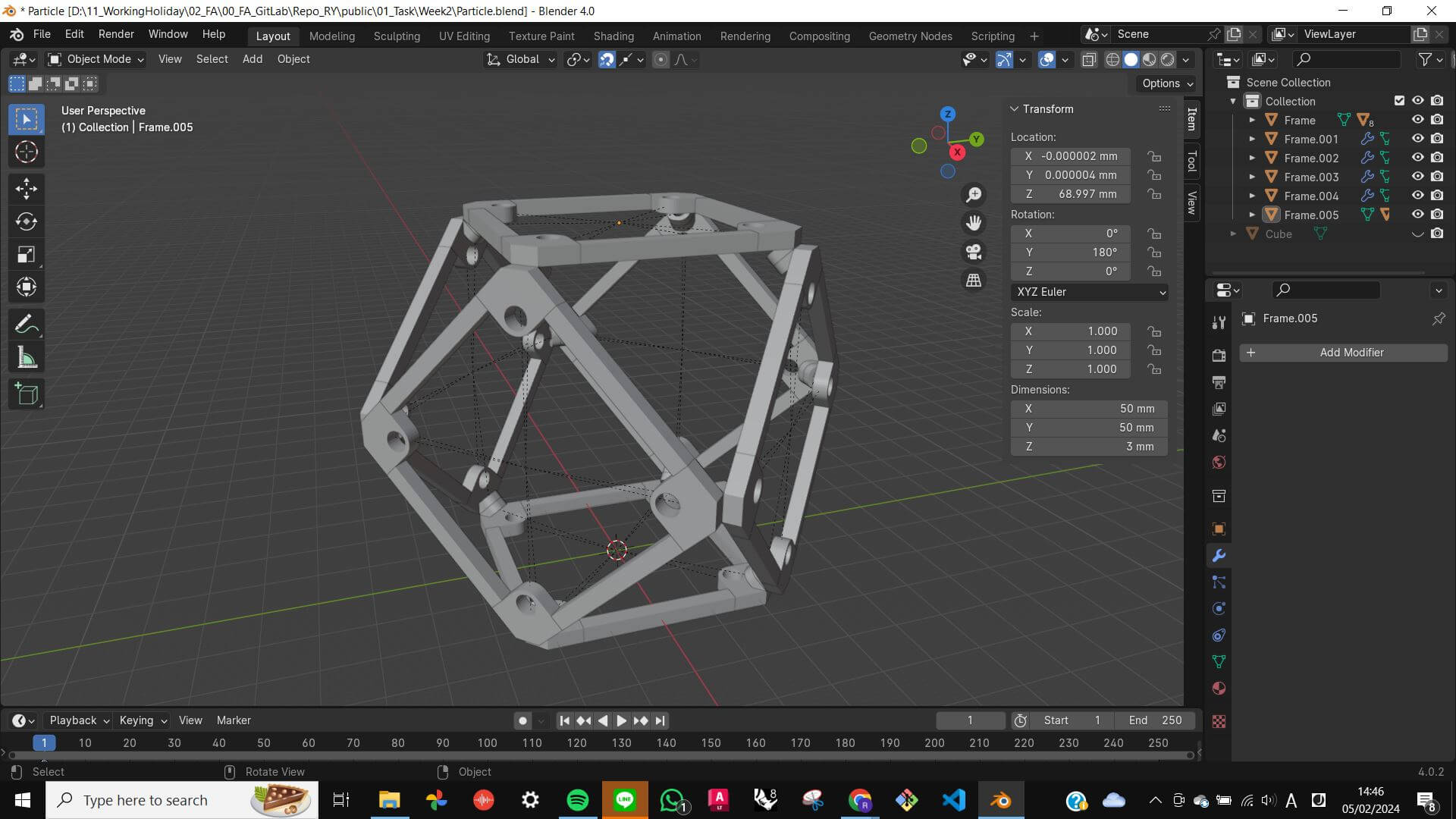
Particles
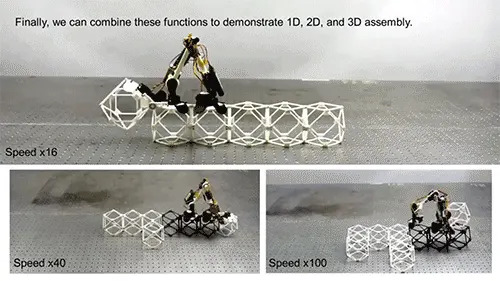
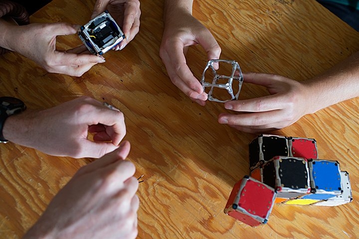
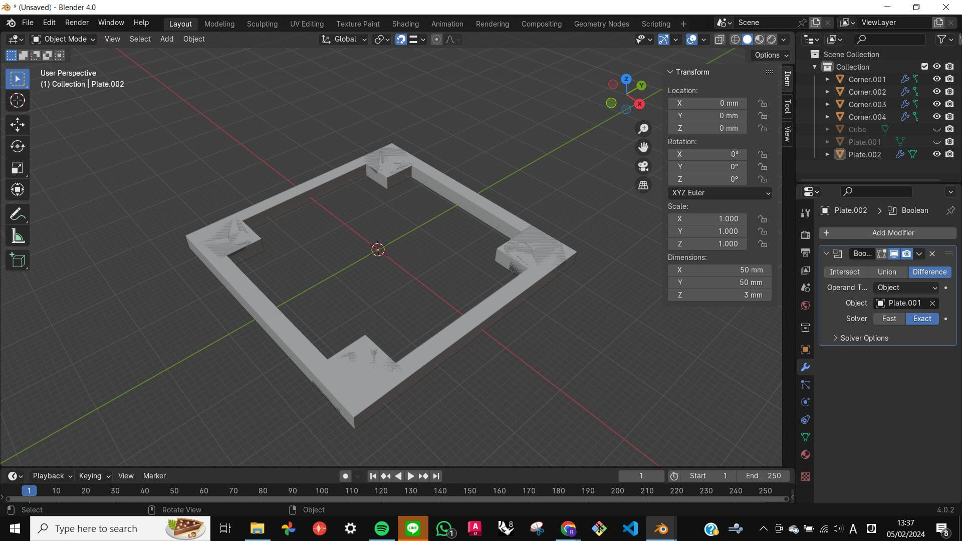
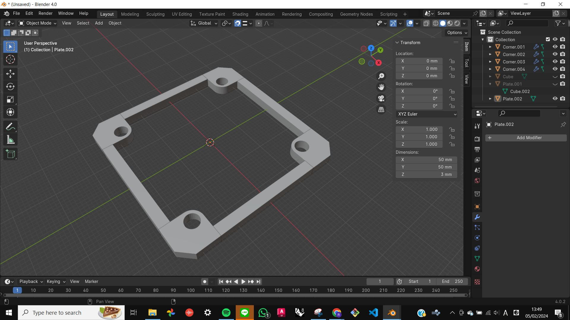
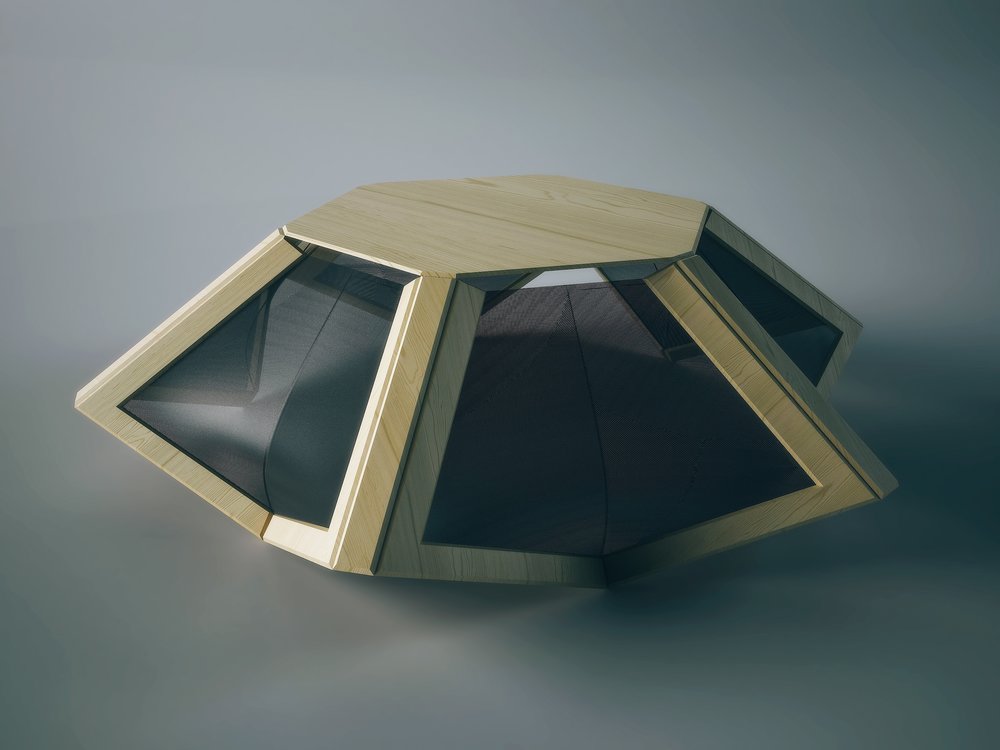
For the week 2 task, I wanted to model a part of my final project. Since my project is about particles I wanted to model a cell of particles. As a reference, I took one shape from Discretely assembled mechanical metamaterials from MIT the Center of Bits and Atoms. I replicated the most simple shape which is a 6 square attached together.
First I started with a box, then modified it to a plate shape. Second, I made a hollow inside using a boolean difference. Third, I made a corner part and duplicated each corner. Finally, duplicated a square frame five times, and created a particle.
Particle Movement (animation)
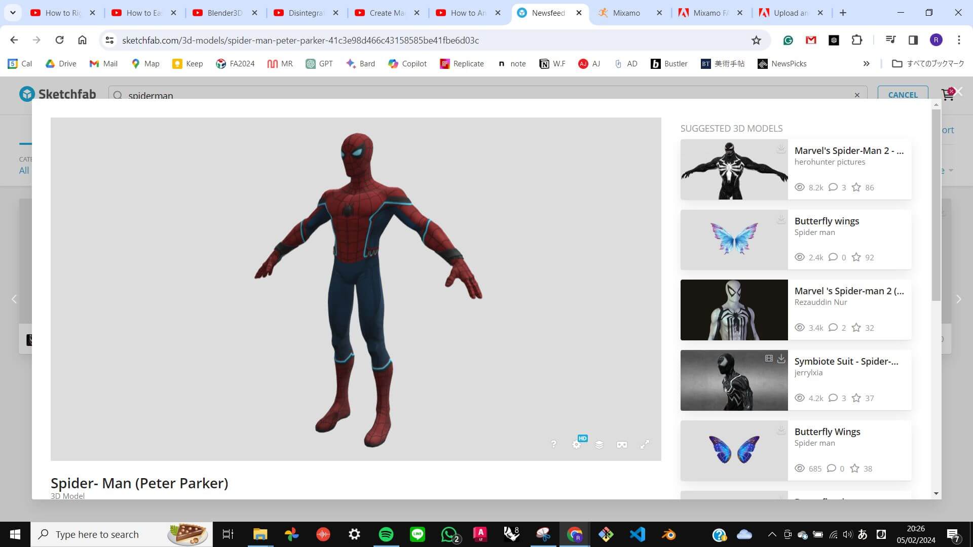
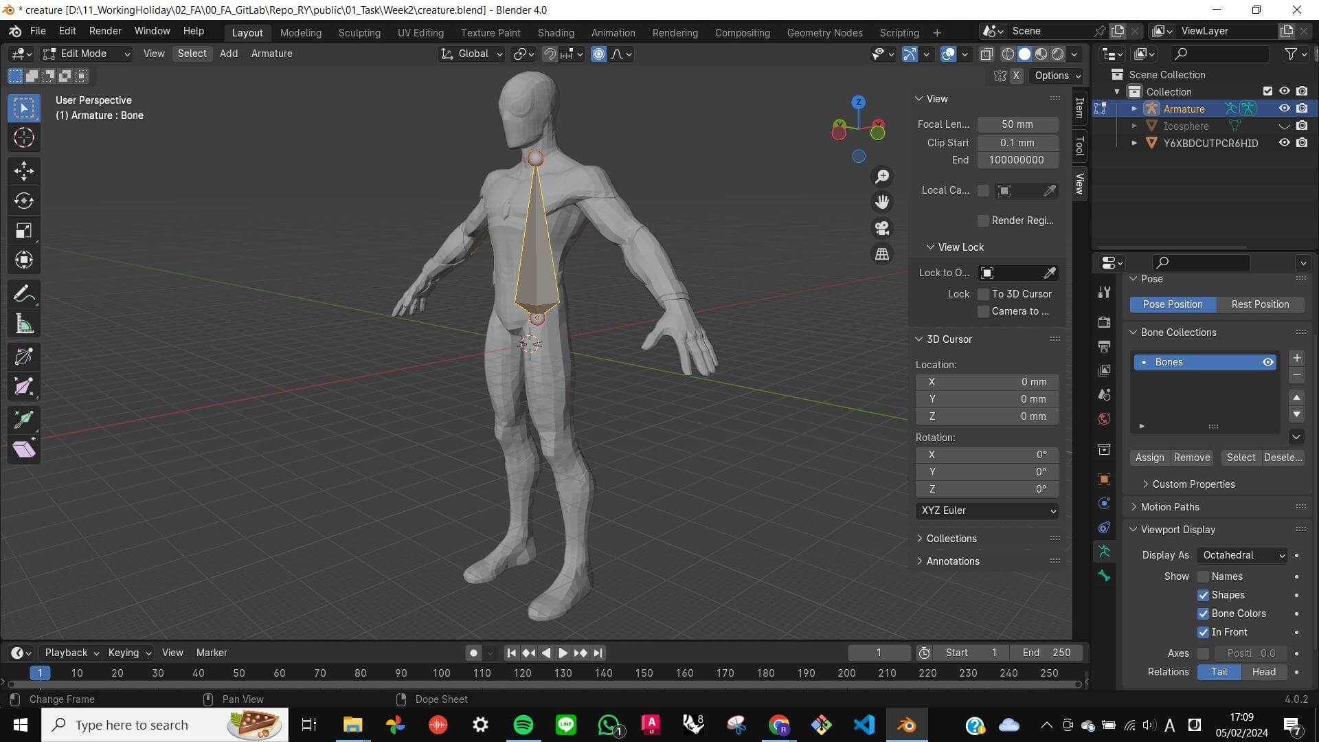
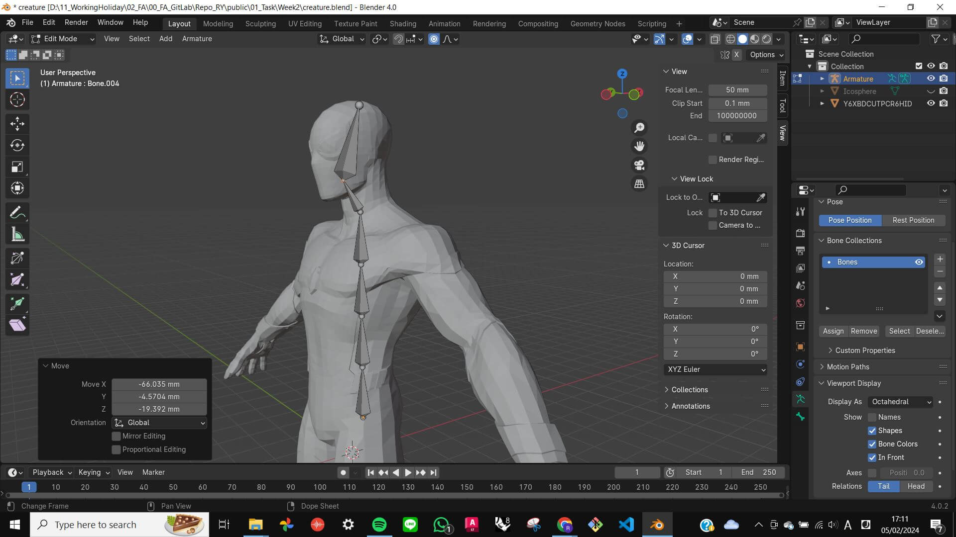
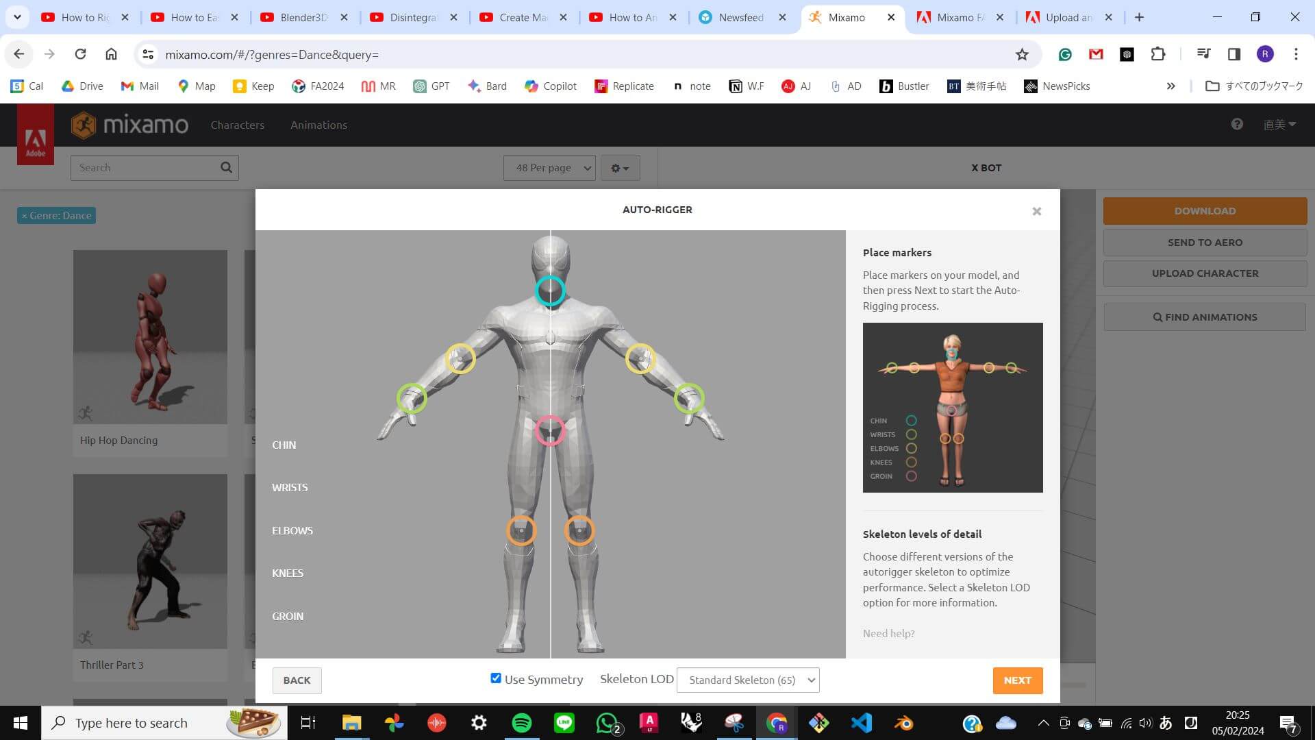
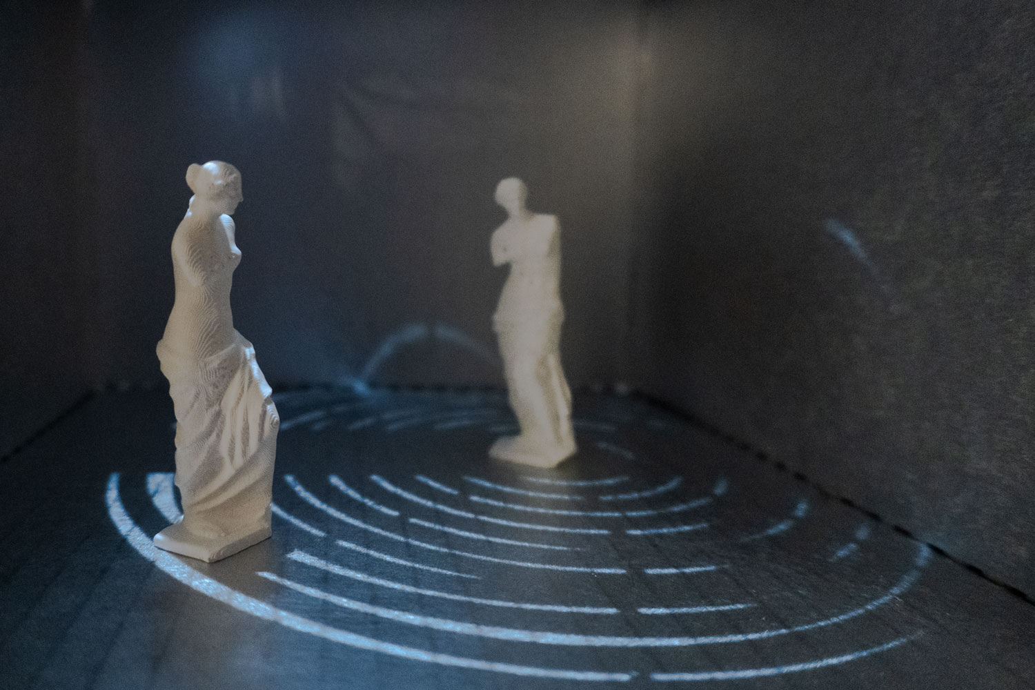
Also, I wanted to create an animation of what my final project aims to look like. Since I want to create aggregate particles moving in response to human movement, I simply wanted to create a model using particle function and animated character movement.
First I imported a human model, then added amature bone. However, it was consuming a lot of time so I used Mixamo to automatically rig my model. Second, I added movement that is available in Mixamo to my rigged model and then imported it to my file. Third, I replicated the model and tried to turn the model into particles. However, it did not work as I thought. Those particles should move according to the rig movement instead of appearing and disappearing in the same place, and also the human model should not appear with particles. I think the particle function might be causing this problem
Key command and method I learn from this challenge.
[Shift] + [A] - [Amature] : add amature bone
Right-click the bone to subdivide
Select point of bone - [E] : to add new bone
[Tool tab] - [X-Axis mirror] : for arms and legs, creating mirrored bone structure
Mixamo: a website that can easily add human amature to model
Personal Review Comments
- Input week, you can try the human movement
- One of the crucial questions is “How responsive do you want it to be?” to be more specific, it is about speed because there is going to be a delay between input and output. If it self assembling all the time then it's going to be difficult. In your idea, the object needs to respond to your movement as it is happening. With lights, it is easy, but when you go with more mechanical things it needs more time.
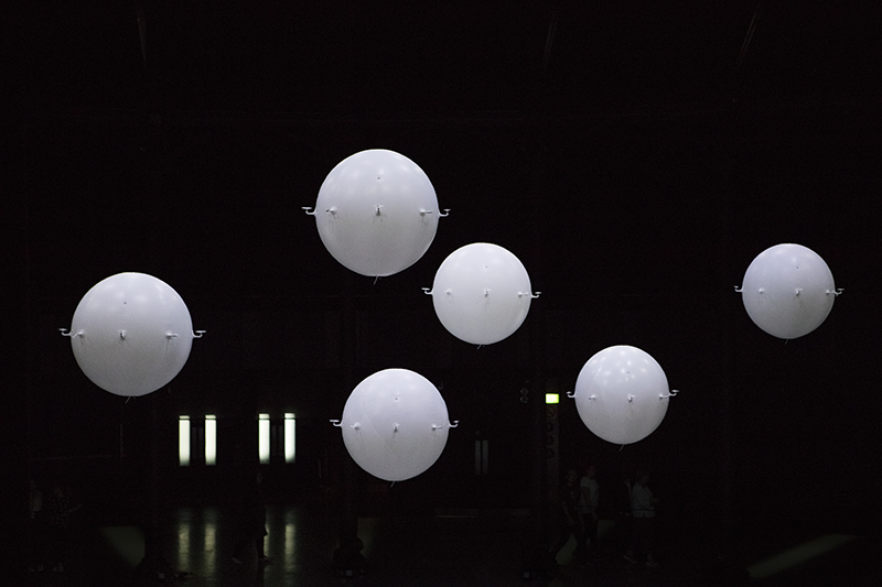
- Zoological, a balloon with plopelas. it's like Zeppelin. It is also slow.
- It is a Give & Take Relationship. About delay.
- Responsive is very important
- As a final project, it will be a prototype or a part of it.
- It is a Modular system (by looking at particles.) A particle is a project itself, so if you achieve a couple of particles at the end, it is a success.
- Spiral development: big idea, break it down into small parts, start collecting small successes and
- A lot of work to do, in the Input part (Kinect will be an assignment), (you can try different inputs, like distance, pressure, temperature. Test them and get values, and decide)
- A big part in the Design and fabricating of the particle itself, and the system,
- Network: Communication between particles is the most complicated part. It is a matter of “How do you want them to communicate with each other?” there are 2or3 options.
- Each particle communicates with the other
- A master brain controls all the particle
- Tree-like network connecting brain and particles (recommended)
- Reference: DNA project from the previous student
- Reference: Neil modular system with USB?
- “How do you want to move?” define more. What is the shape of the particle? Linear, rotate. Descending on movement, there is a different mechanism.
- For start, maybe light and sound?
- This will change your project. There are 2 different directions.
- If you want to focus on particles, you will end up creating a particle or 2,3.
- If you want to do more have the network and respond altogether, it will be more like a kinetic structure, where everything is fixed and one part moves as a response.
- You don't have to choose now, could run with both possibilities, but at some point, you need to choose one.
- Reference: MIT Self Assembly lab ( you might find something in between)
- Reference: inflatable?
- There are many ways to represent it as an output.
- Establish the element your project has to have!!! At least 2, that you can always come back to.
- Make it a bit more down to earth. Clear idea
- Anyway you go, start small, and scale after is easy. It is like Solving problems one by one, facing all the problems at once or
- You need to define the object you want to create. Do a drawing of what you want to have at the end.
- It's a very ambitious project but you did a very nice job with the description and stuff. Neil will be happy
- Break it down, see all the possible, see the direction the project could take and look for references.
- Try to find references in the open source world so you can take background technology. Fablab, MIT. (words are “kinetic”)
Reference from Personal Review
Particle
Movement

Previous Students Project


Questions to realise the project
After the personal review, I thought carefully through the questions I needed to be able to answer in order to realise the project. I wrote down a bunch of words that define my project and started to reduce them so that I could realise some keywords that define my project.
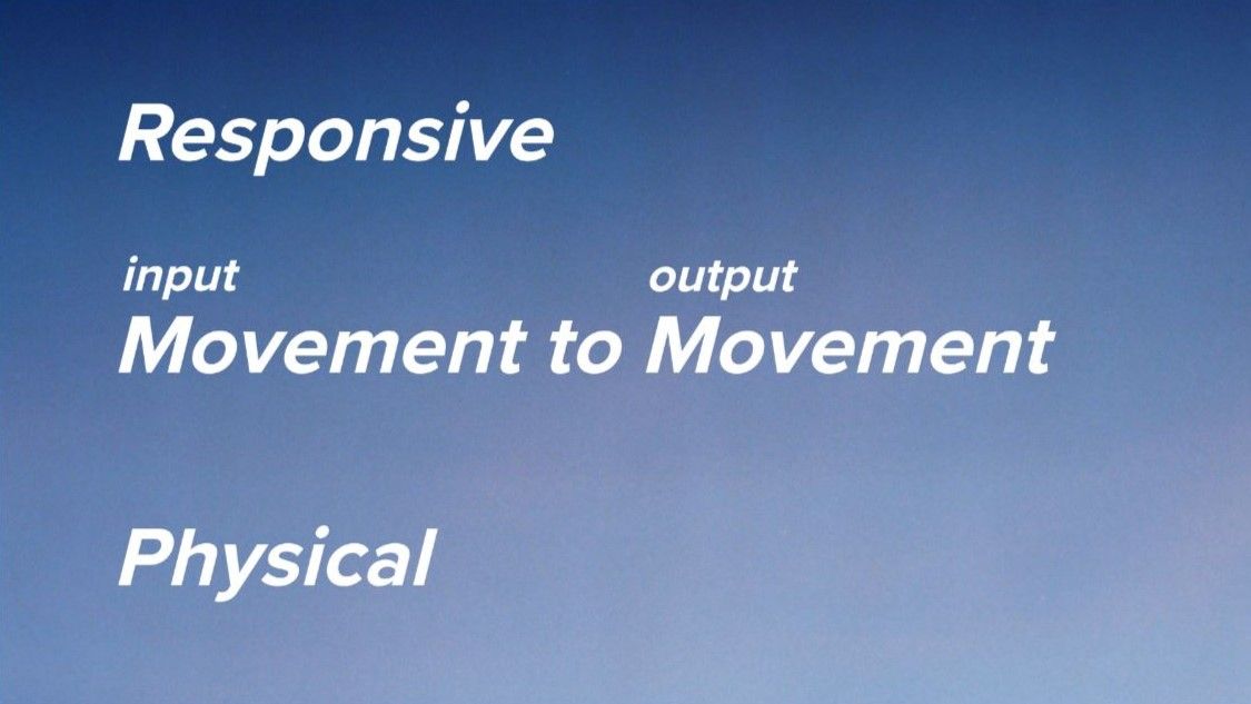
After all, the core of my final project should be Movement as Input, Movement (Output), Responsive (instant feedback), and Physical.
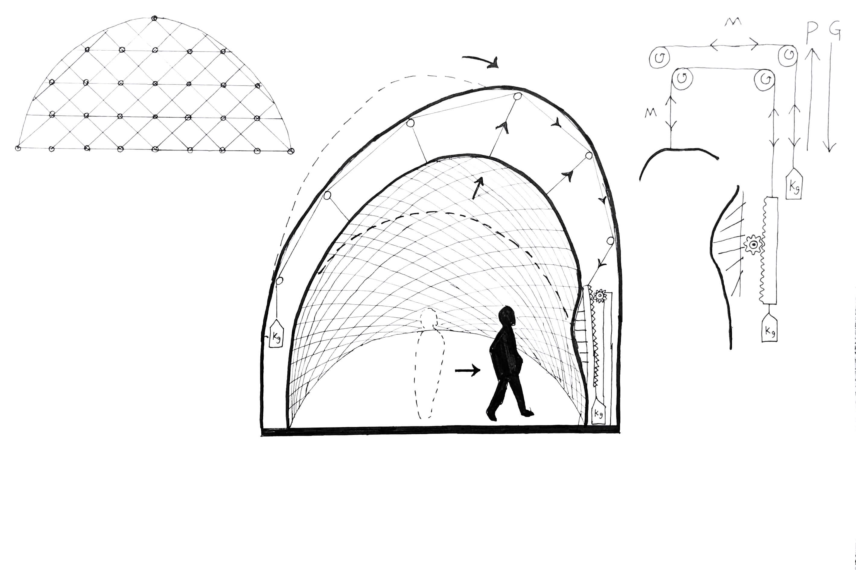
Idea Sketch
This is the first idea sketch. The idea is to make an architectural model that moves according to human movement.
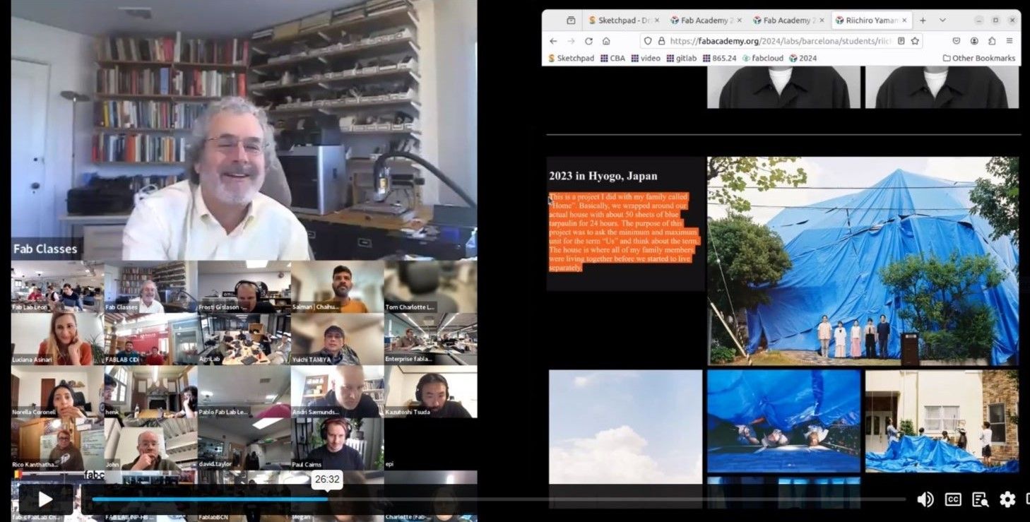
Global Review
I presented about the current state of my final project during my global review in
Week 3 Computer-Controlled Cutting
Neil and the other audience gave me some nice references related to my final project. See below.


Final Project has Changed !!!
2nd Idea
Inspiration
Since I had such a fun time playing with paste printing in
Week 5 3D Scanning and Printing
, I started to shift my final project towards it.

Statement
If the future will be like
How to Make (Almost) Anything (AImost) without Making Anything
(AI Recitation: Presentation given by Olivia Seow, Harvard University Amira Abdel-Rahman, MIT Center for Bits and Atoms Valdemar Danry, MIT Media Lab) , as a person who enjoys making,
I will be very bored and sad.
I saw a glimpse of the sadness and boredom when I was sitting in front of a 3D printer and just waiting to finish the job. Instead, I want to communicate with the machines. I want to collaborate and make things with the machines. I want to have fun with machines in the process of making.
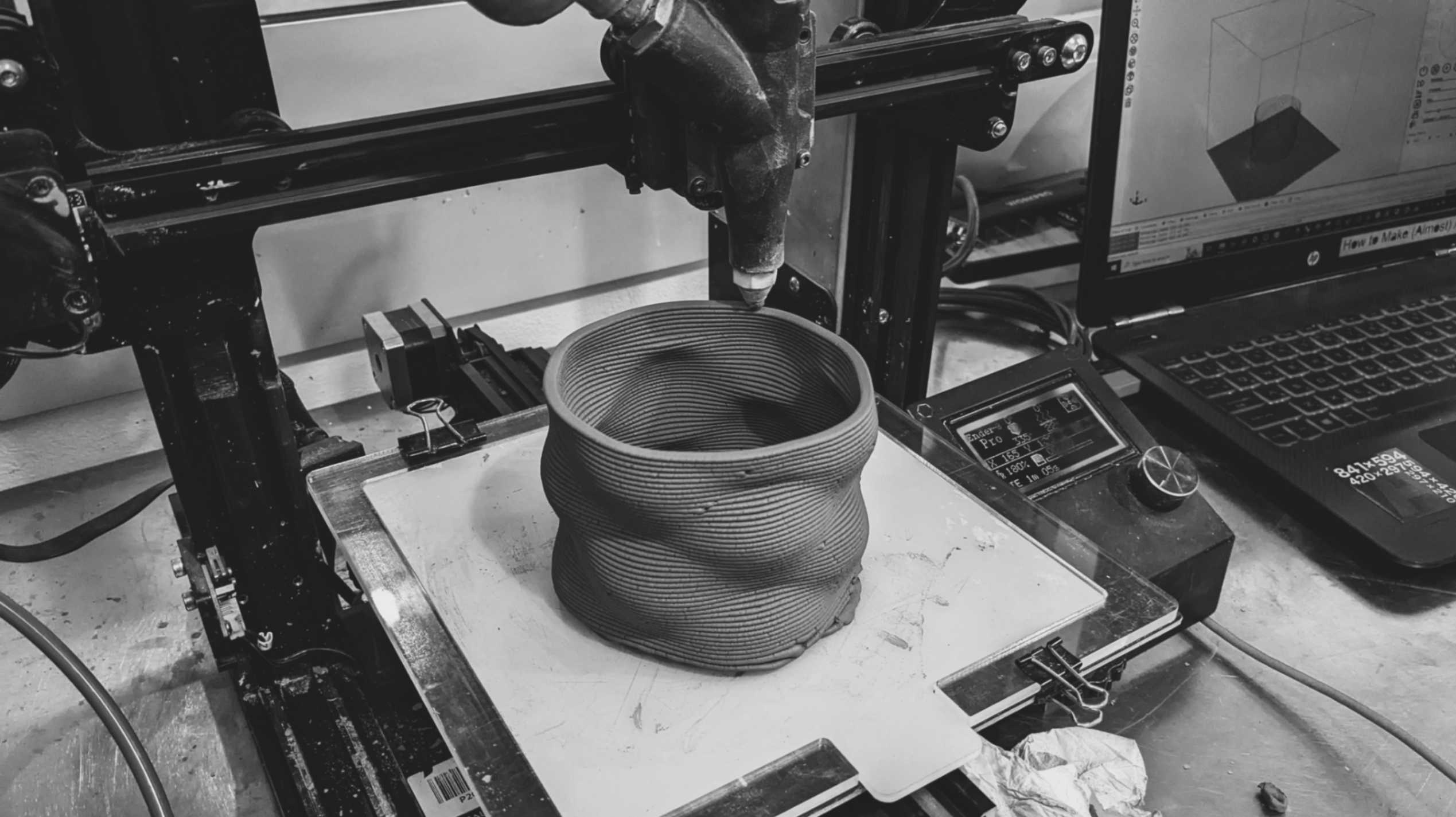

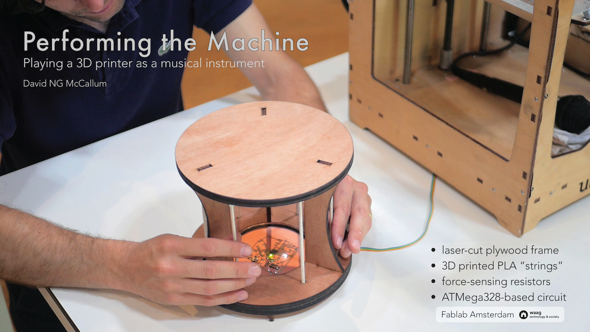
Idea
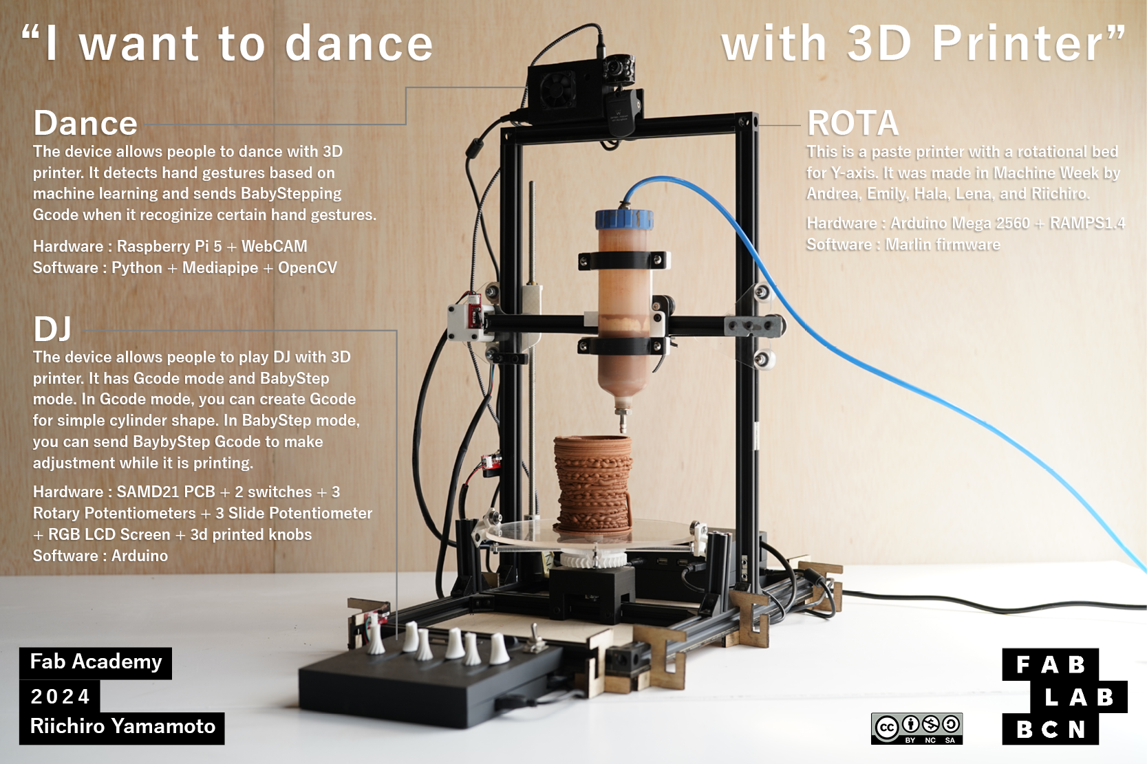
So now, the ultimate goal of my final project is to dance with a 3D printer while it is printing and create a unique print piece that shows traces of the improvised collaboration.
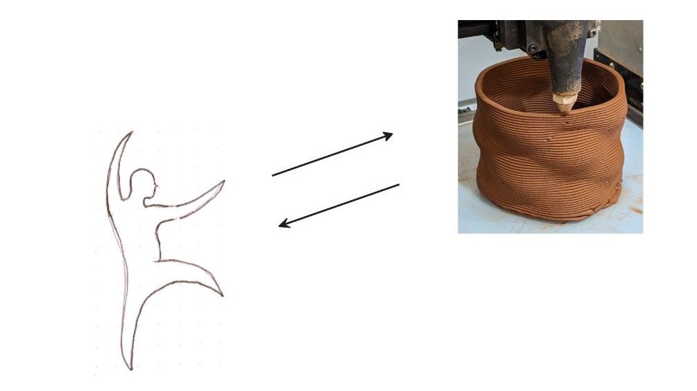
The ideas have changed but the principle has not changed. It will always be Movement(Input) to Movement (Output), Responsive (instant feedback), and Physical. The big difference is the responsive movement will be happening during making rather than with an already-made structure.
I found the Babystep function very interesting. It is a default function that 3D printers have. It is mainly used for Z-axis adjustment for a better print finish. But to me, it is a simple example of communicating with the machine, and collaboration between humans and machines in the process of making. Moreover, the finished print piece will have traces of co-creation.
Isn't that beautiful?


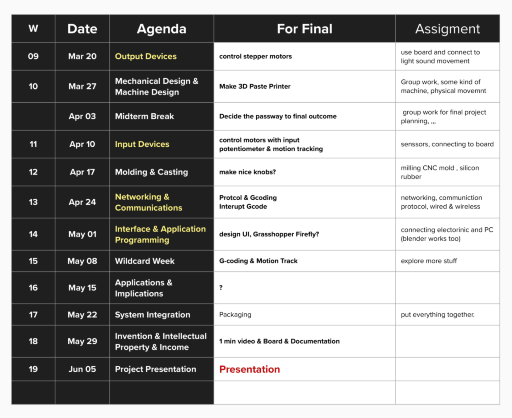
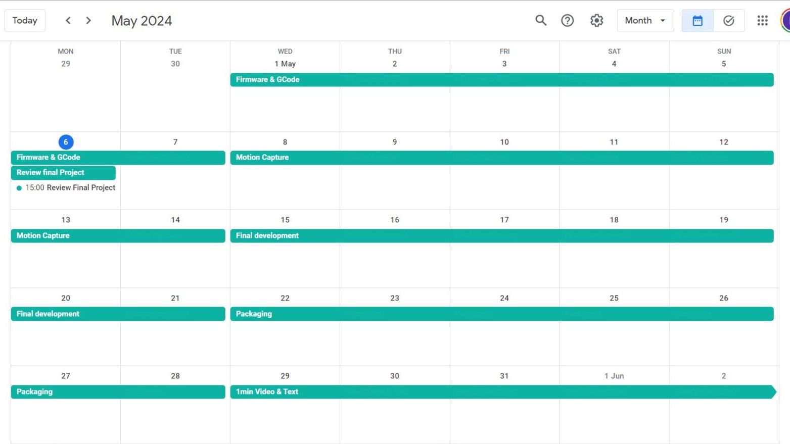
Schedule
I made a schedule for developing my final project according to what we will be learning each week. In this way, I will be able to synchronize weekly assignments and final project development.
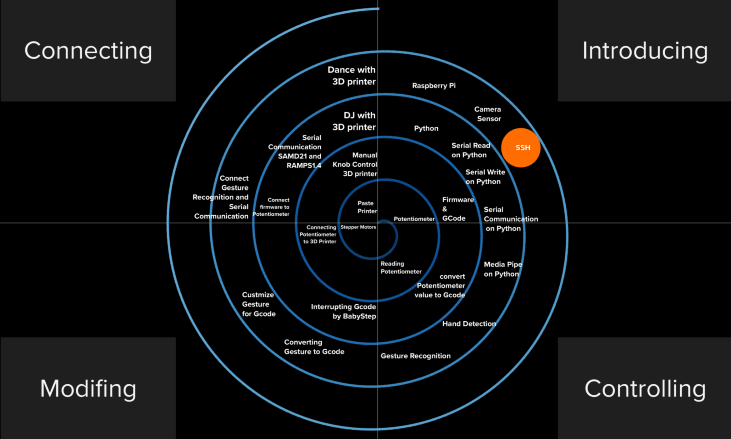
Spiral Development
Since I was able to synchronize my final project and weekly assignment, I naturally started spiral development. Since I made my 1st iteration simple and not too complex to achieve, I am aiming to finish 1st iteration as soon as possible and use the time left to develop more on input devices and GCoding
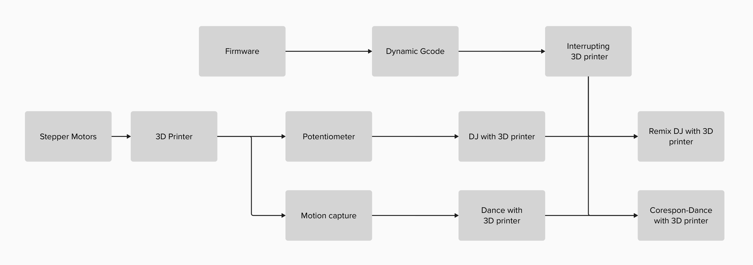
Pathway
Start with simple input such as potentiometer.
Make the sysytem work with Firmware and GCode
Then try complex input such as camera sensor

0.1 Stepper Motor
Undestanding how to control stepper motors.
Documentation is onWeek 9 Output Device
0.2 Paste Printer
Undestanding more about 3D printer by actually making 3D printer.
Documentation is onWeek 10 Machine design
0.3 Potentiometer
Controlling motors on 3D printer by potentiometers.
Documentation is onWeek 11 Input Device
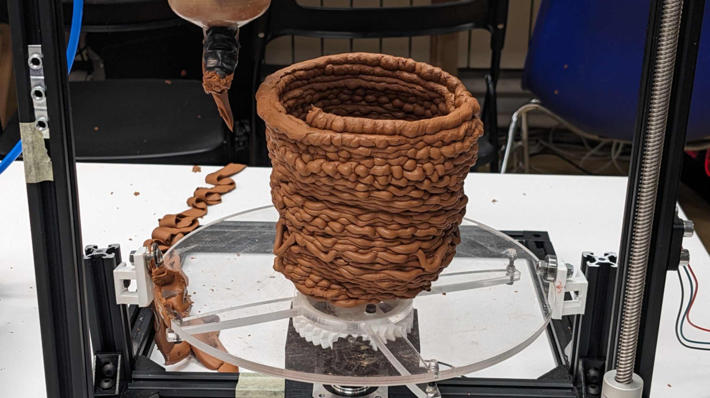
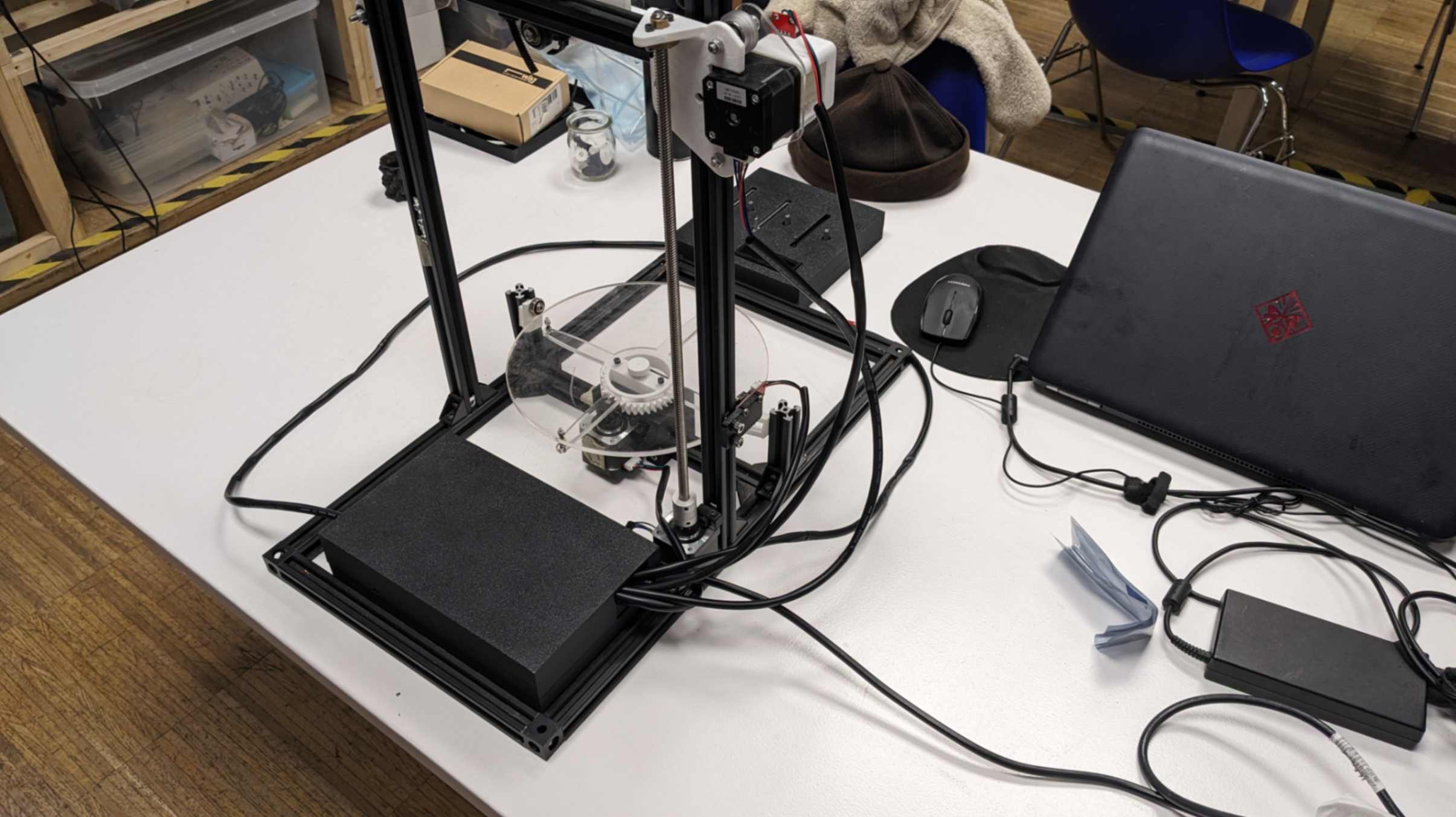
1.0 Manual Control 3D printer
Week 11 Input DeviceAs a result, I was able to paste print a piece but it was very difficult to control the printer. To make it better, Indeed to fix the things below.
- function to stop motors
- Z motor speed need tobe be slower
- X motor can move faster
- Y motor should move faster
- Slider knob at middle should be move in either of direction
- Rotational knob at lowest value should stop motor
- Nicer to have another motor for extruder
This is the outcome of 1st iteration.
FilesCode_StepWithoutDelay-Potentiometer-3StepperMotors.txt
1.1 Firmware and Gcode
This was achieved by Week 10 Machine Design. We tried using Marlin360 however we end up using Marlin for the firmware.
Documentation is onWeek 10 Machine Design
Files
MARLIN 360_fromAndrea.txt
Marlin Configuration_ROTA.txt
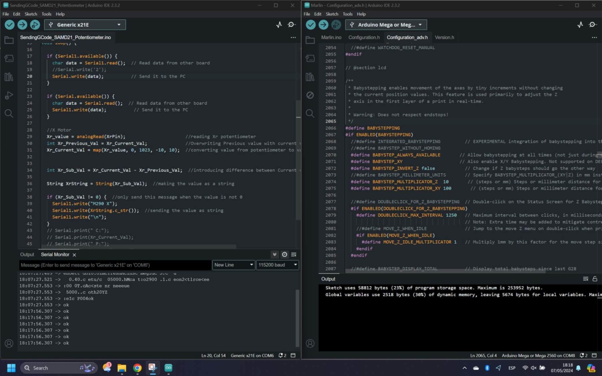
1.2 BabyStepping
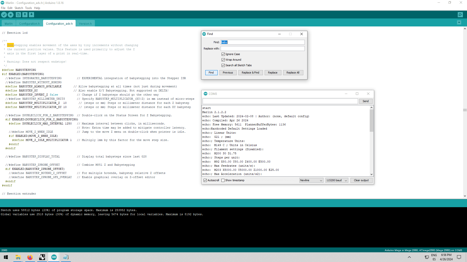
First I was looking into Live GCode Sending / Dynamic GCode, but I was not able to find any reference for what I imagined to do. Then I went back to my starting point which is the BabyStepping function. After researching about it a bit more, I found out that there is a Babystepping function for the X and Y axes as well. So I followed this tutorial and was able to activate the BabyStepping function and create movement while the printer was printing.
Files
Marlin_Configuration_adv_ROTA.txt
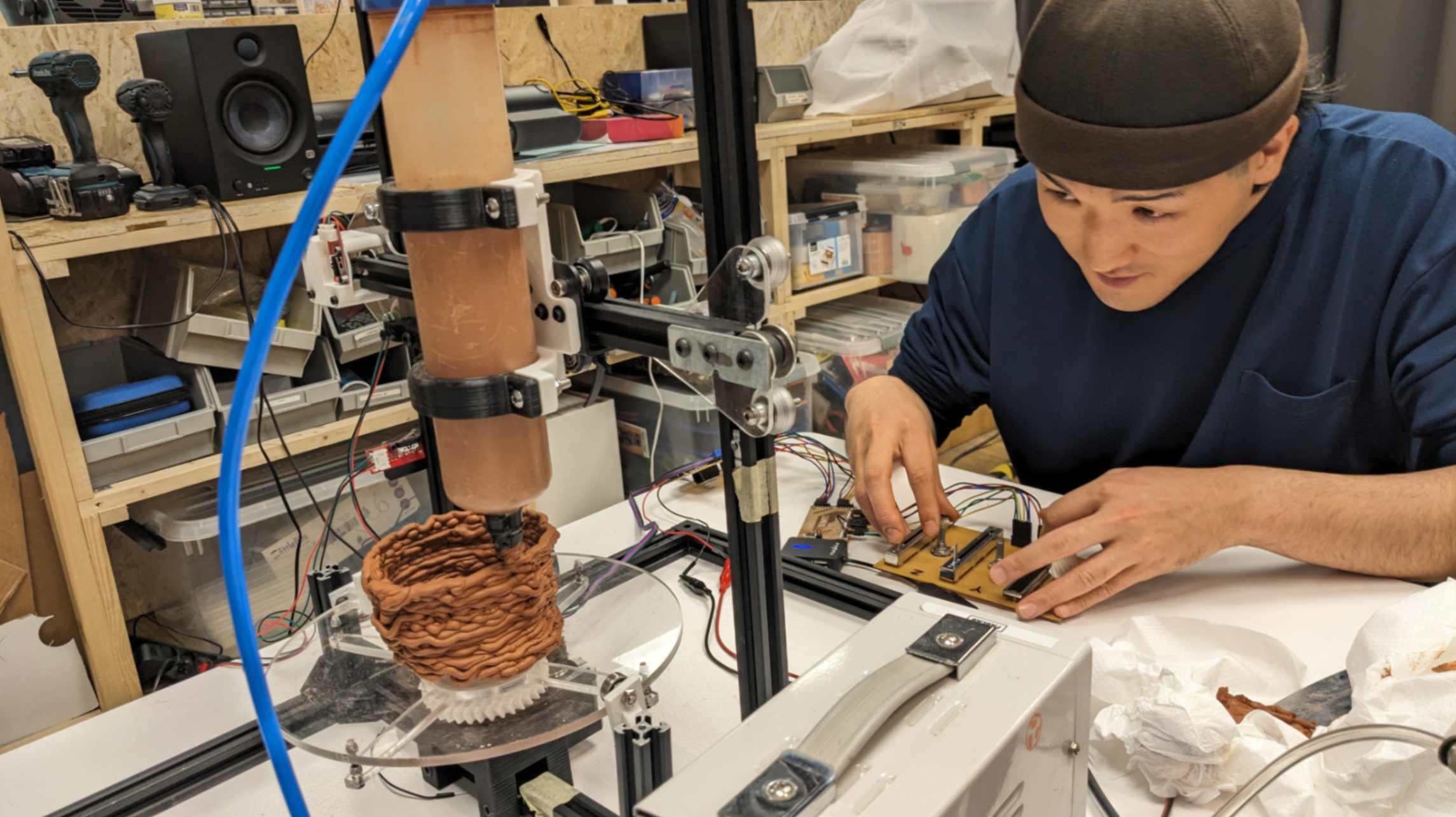
1.3 Potentiometer + Firmware
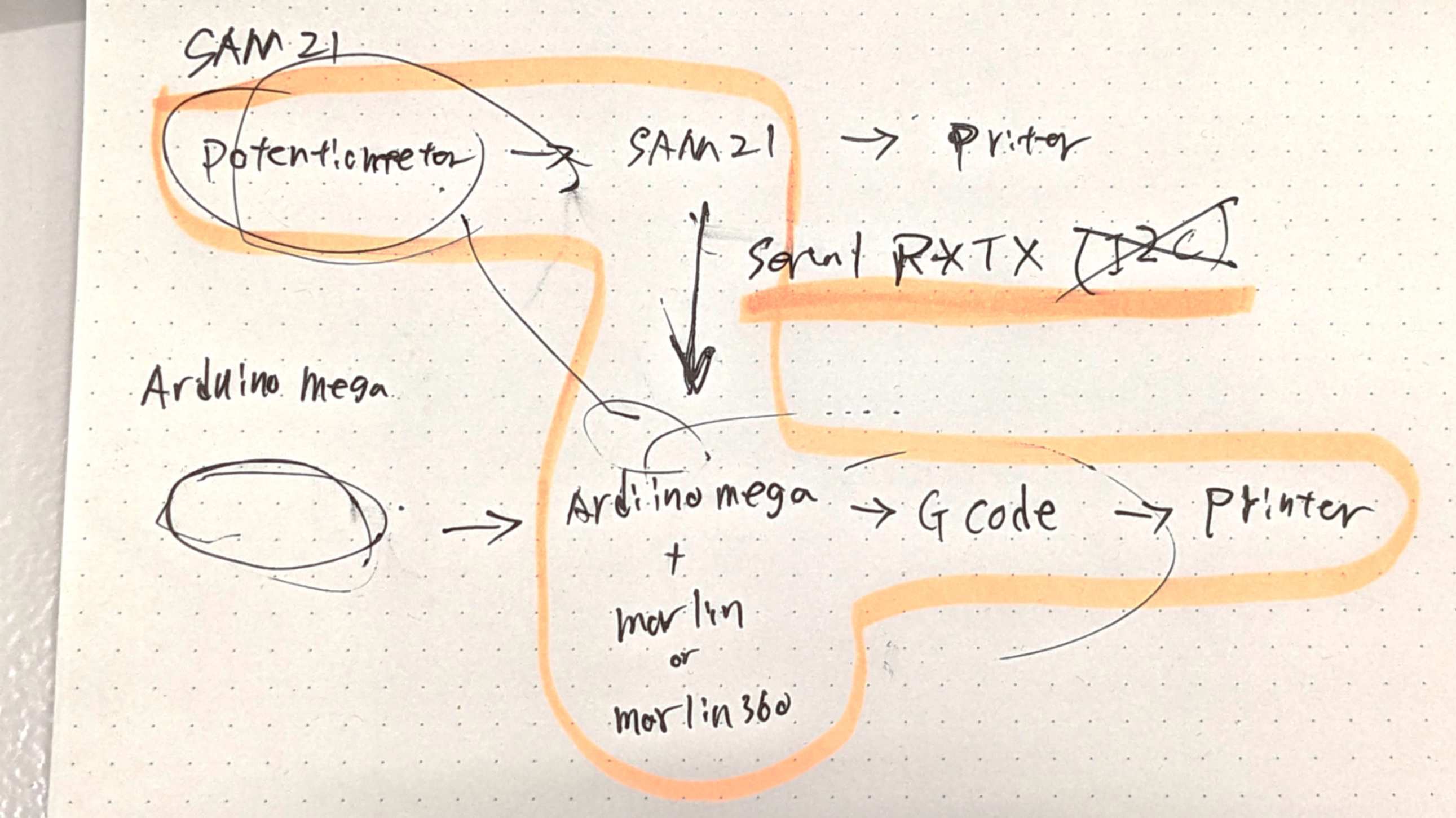
Now I needed to use the BabyStep function with a potentiometer. At first, I had no idea how I should move on because I had two different boards able to to the different things which are controlling with a potentiometer and sending GCode with firmware, but My tutor helped me understand what needs to be done.
The simple way is to connect SAMD21, which is connected to Potentiometers, and Arduino Mega2560+RAMP1.4 which has firmware, by Serial communication. This is something I learned recently from
Week 13 Networking and communications
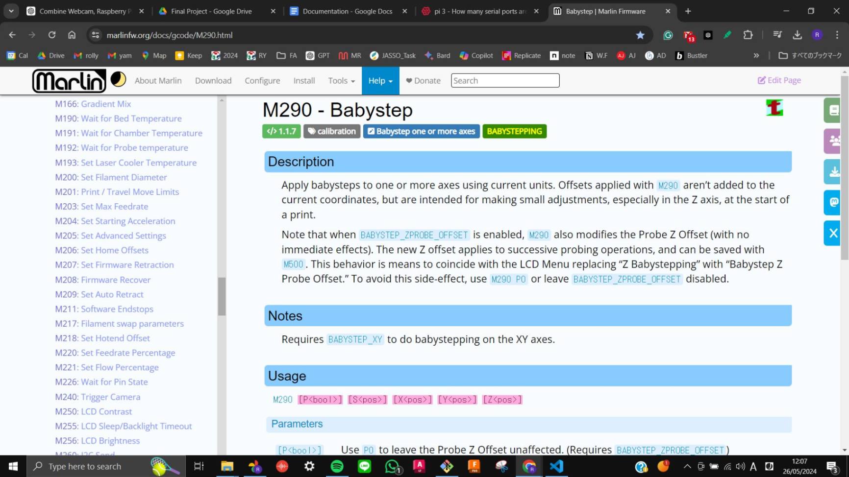
By researching on the web I found this page. According to this page, there are 4 serial ports on RAMPS, and Serial 2 was free for me to use. (Serial 2 is often used for LCD screens which is not my case.)
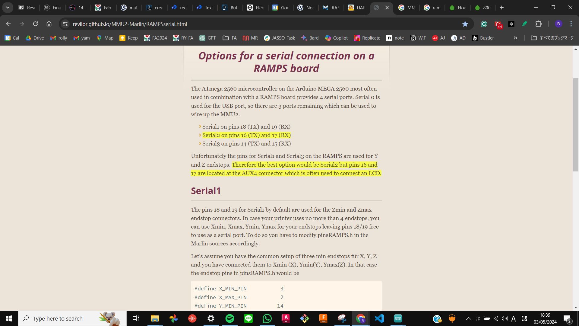
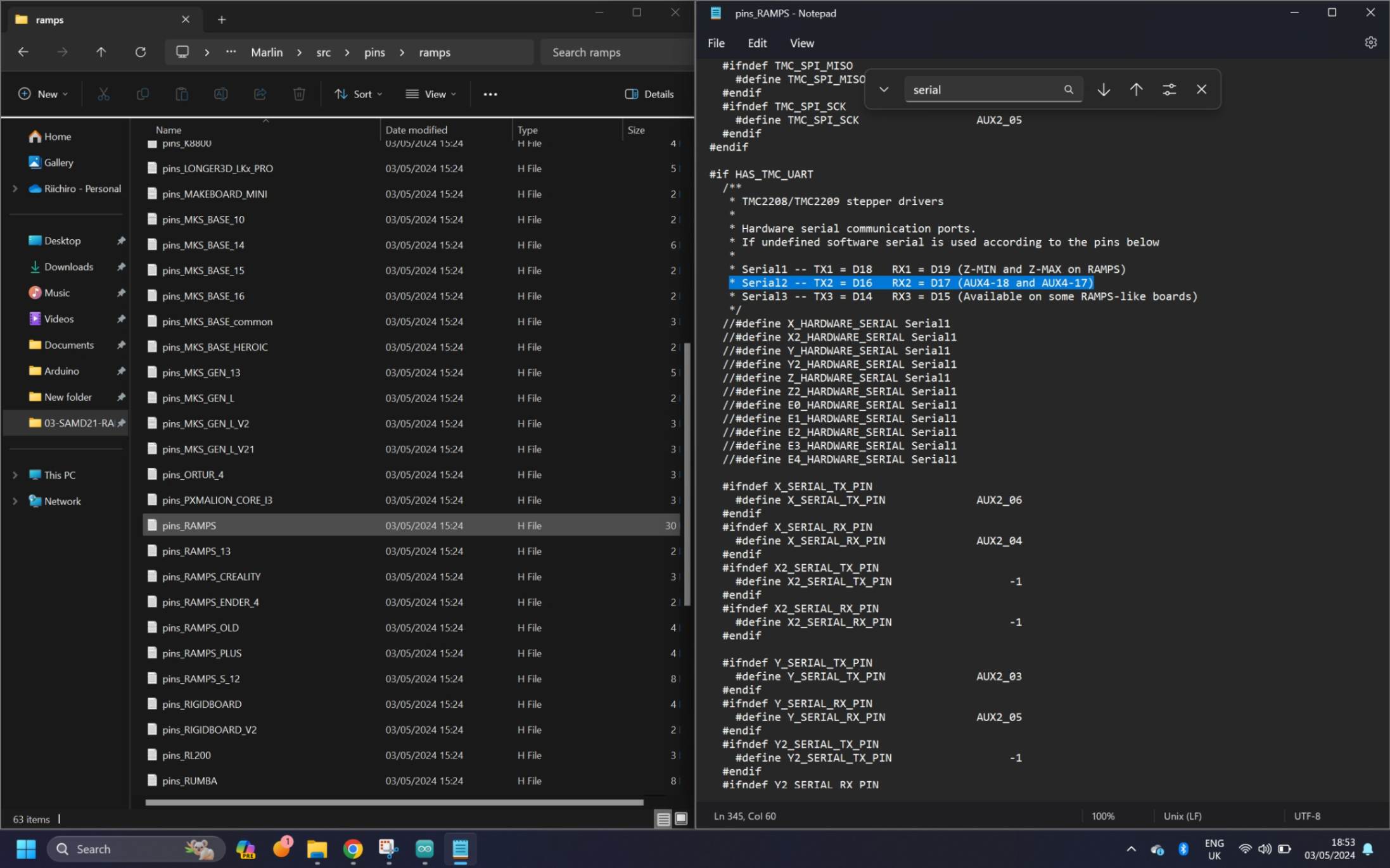
This can also be checked if I look into the Marlin folder - src - pins - ramps - pins_RAMPS.
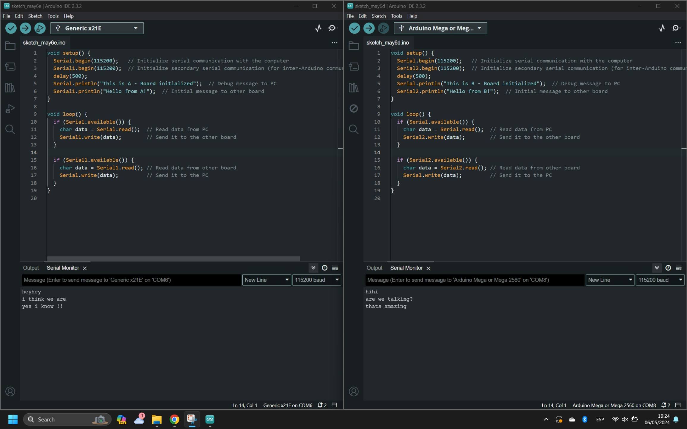
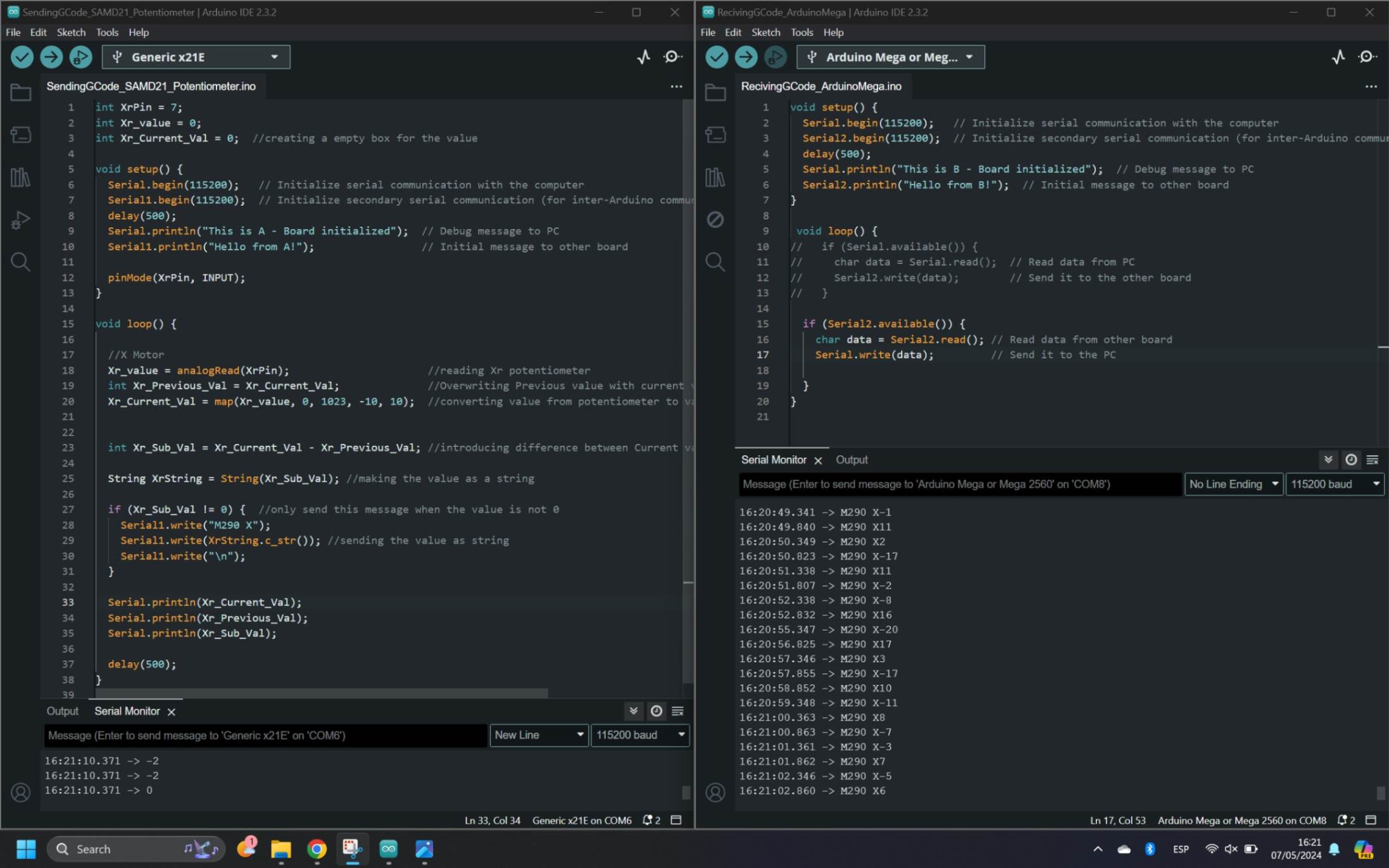
First I used the Serial Communication example code from Week 13 Networking and communications To establish the conversation between the 2 boards. This was a simple task since I only needed to change the serial port number. In this case, Serial0 and Serial1 on SAMD21 and Serial0 and Serial2 on RAMPS were opened.
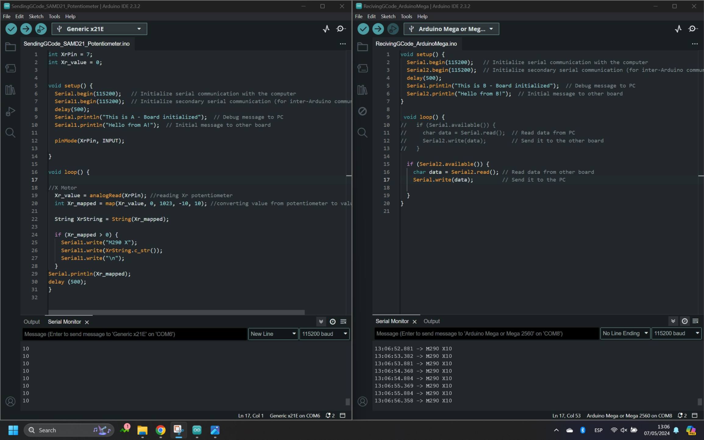
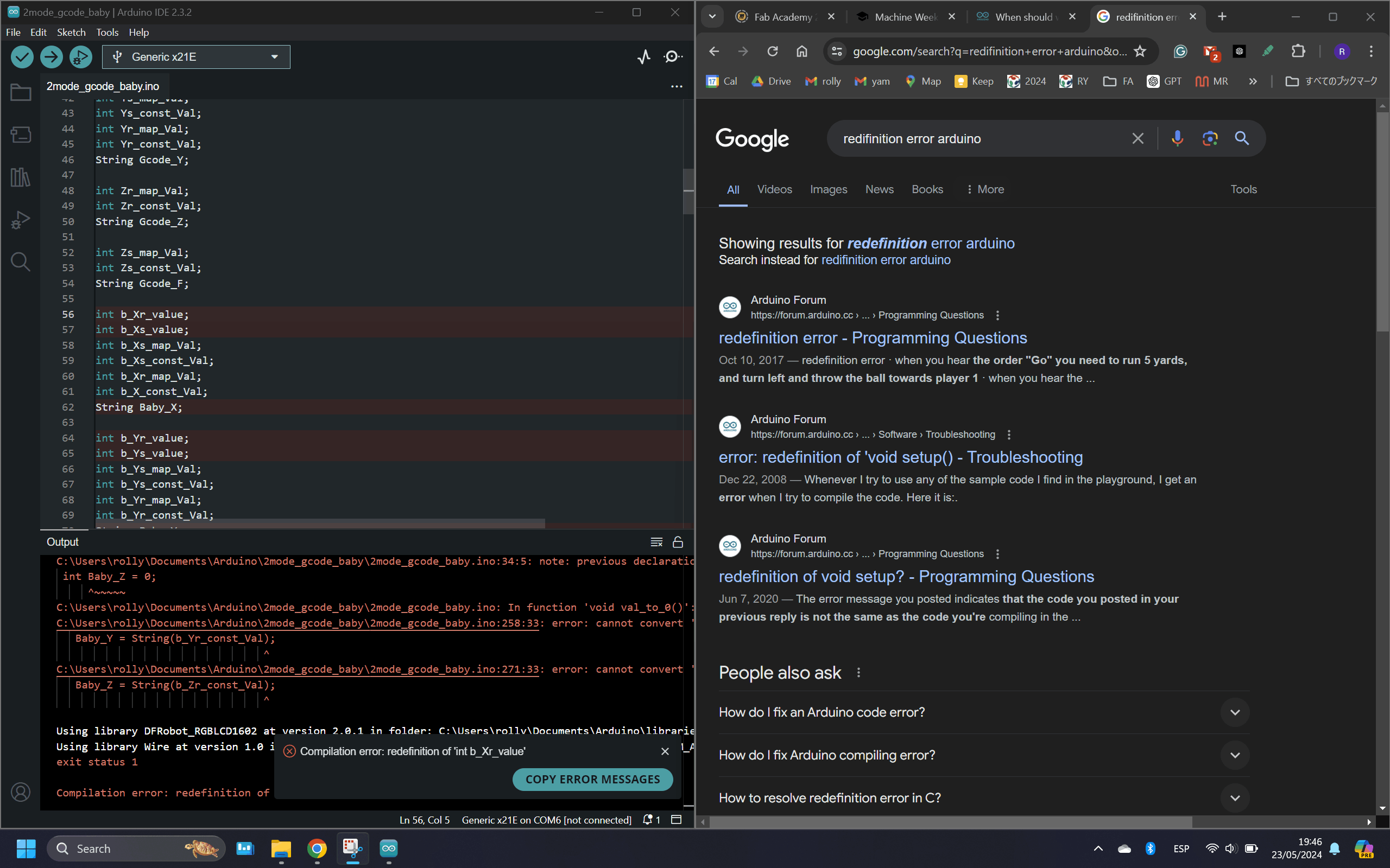
Next, I modified the SAMD21 code to get the value from the Potentiometer and sent it as Gcode to RAMPS. There was a small problem, the value was not printing correctly. This was because as a default C++ language, some numbers are translated to different characters in the process. So the solution was to make the values as String. After That, I was able to send Babystep Gcode in real-time with the value from the potentiometer.
However, I needed to modify the code a little more, because the Babystep is relative therefore it will keep moving as long as it gets value from the potentiometer. In order to do this, I used the technique of converting the previous value equal to the current value. This is similar to the Blink Without Delay example I learned from Week 11 Input device
I added these three codes below, in order to only print when there is a difference in potentiometer value.
int Xr_Previous_Val = Xr_Current_Val;
int Xr_Sub_Val = Xr_Current_Val - Xr_Previous_Val;
if (Xr_Sub_Val !=0)
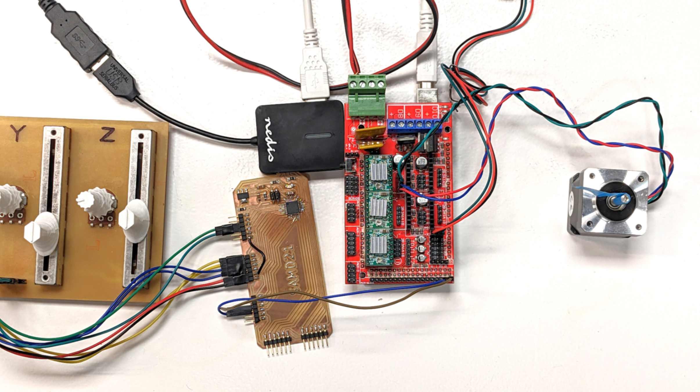
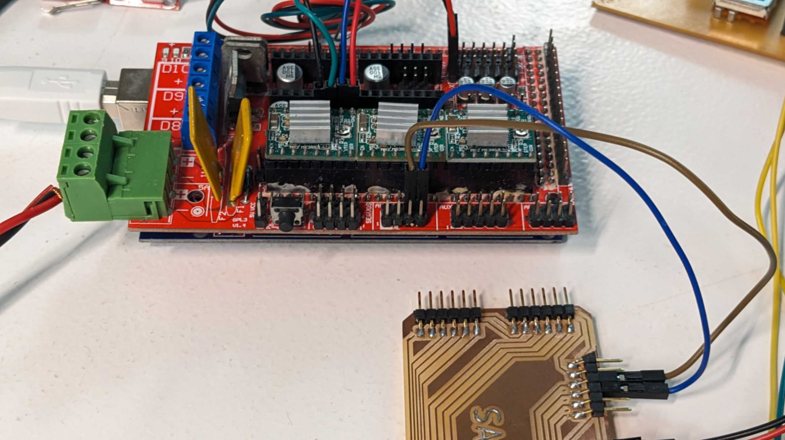
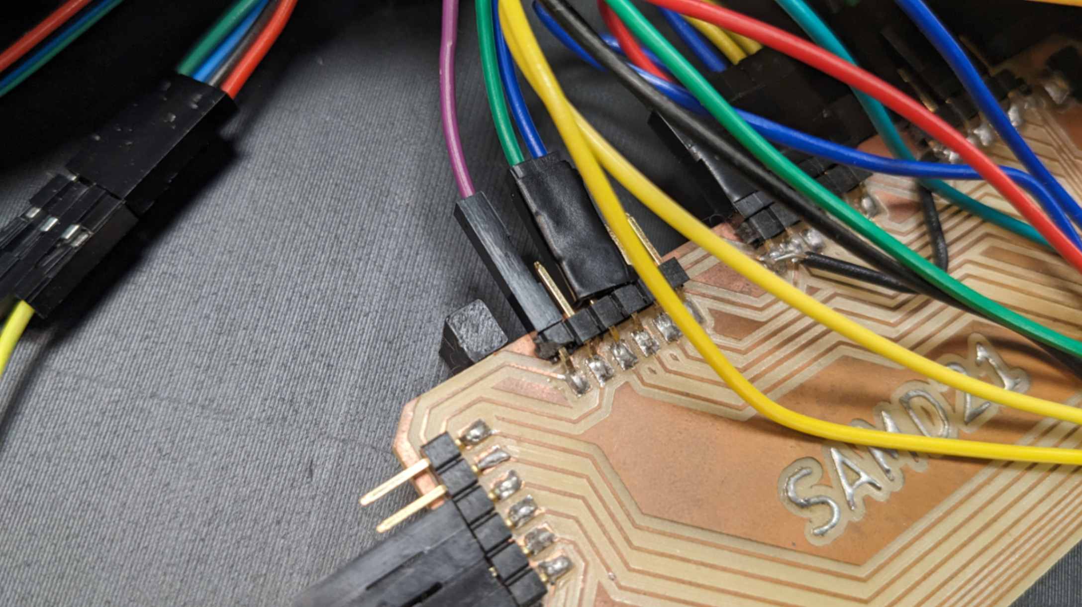
Now that I developed a way to send Gcode from SAMD21 I needed RAMPS to receive the Gcode and function with Marlin firmware. This was a problem because Serial0 is the default serial port to receive Gcode, but I wanted to use Serial2. My tutor advised me that I have two ways. One would be to go deep into the firmware program and change the default setting which is more complex. Another would be to connect SAMD21 to Serial0 which can be done with a physical connection and might be easier. I decided to go for the easier option.
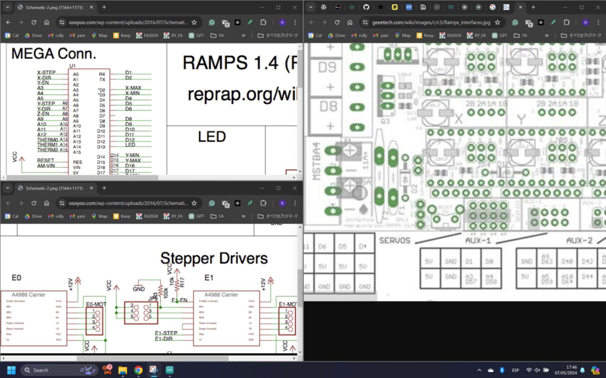
By looking at the pinout and schematic of Arduino Mega and RAMPS, I found out there are exposed TX and RX pins for Serial 0 communication. So I simply connected those pins to SAMD21, changed the serial port number on the SAMD21 code and uploaded marlin firmware to Arduino Mega.
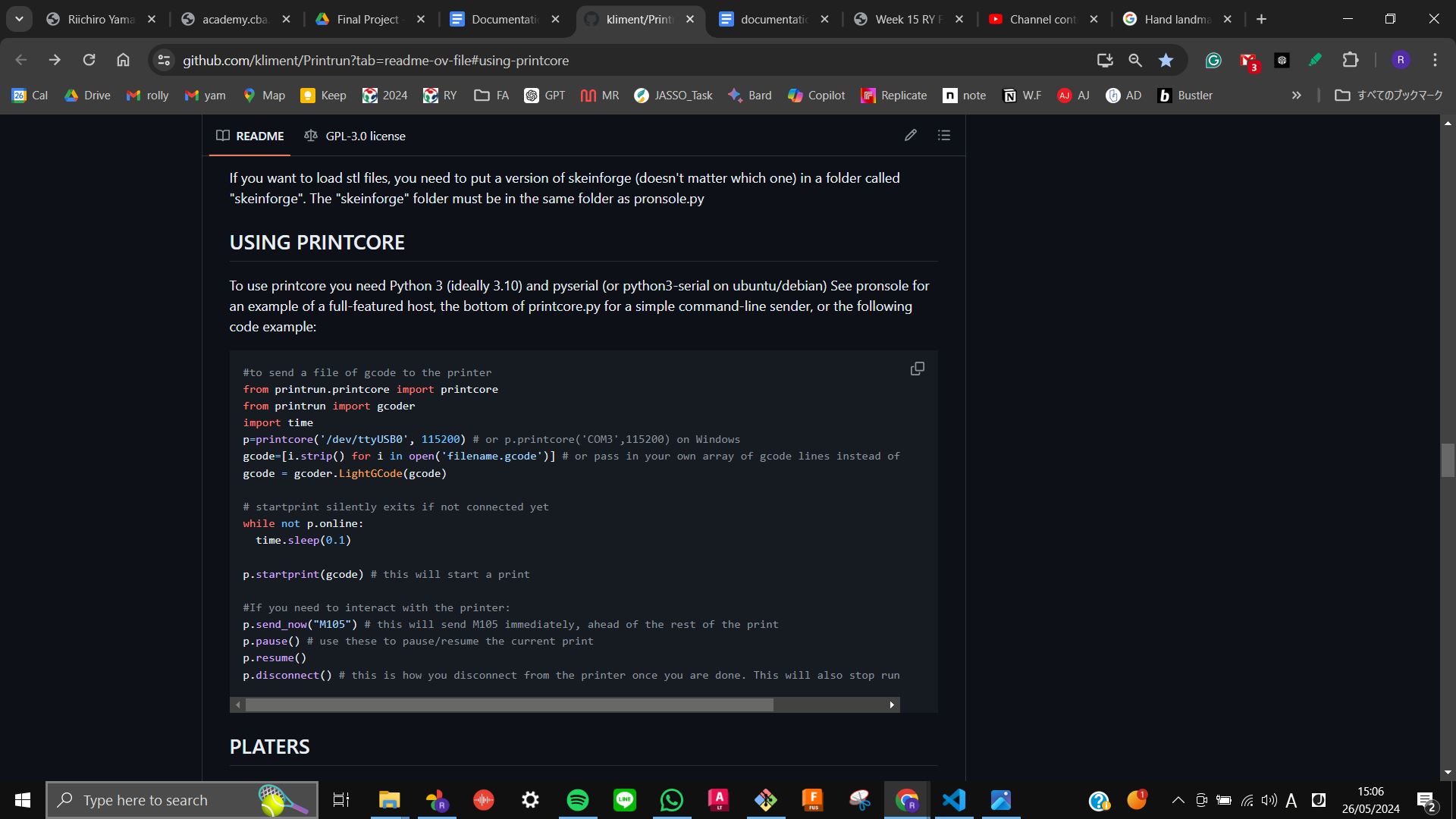
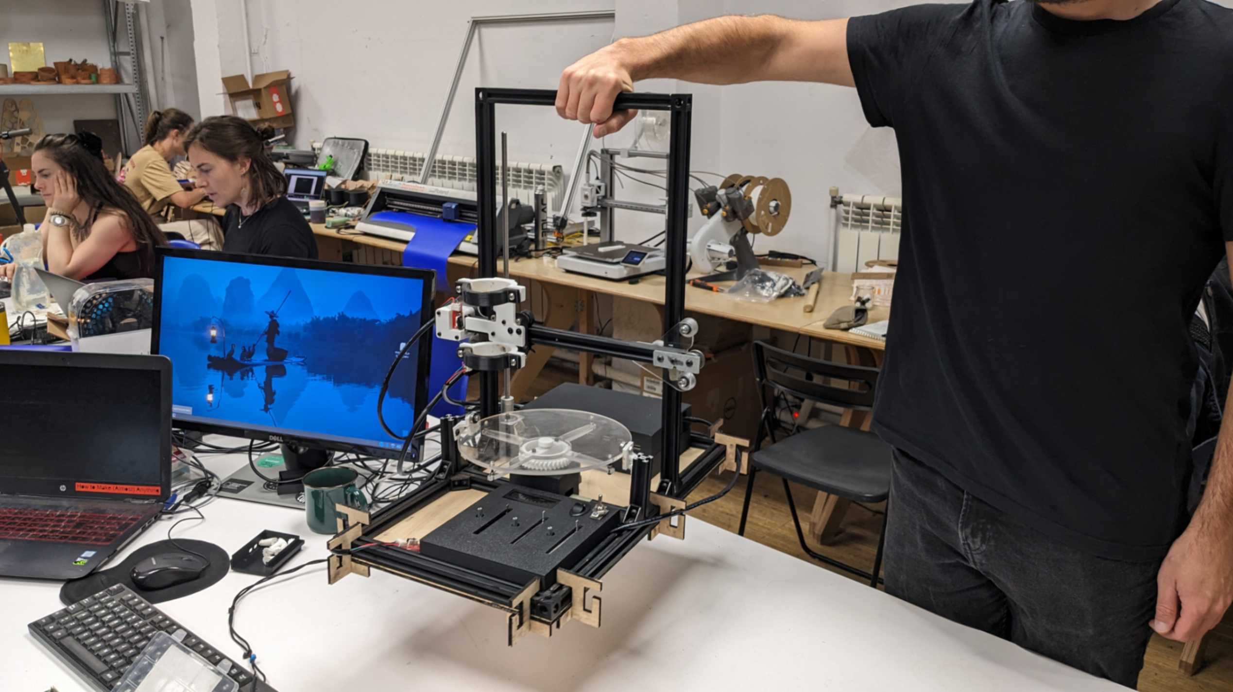
2.0 DJ 3D Printer
Finally, I can run Gcode and make Babystep with a potentiometer while the printer is printing.
(4 Weeks until Final Presentation)
This is my weekly task to achive until the final presentation.
What is left to do?
Week0: Potentiometer + Firmware
Week1: Motion Capture
Week2: Motion Capture + Firmware
Week3: Packaging
Week4: 1 min video + presentation board
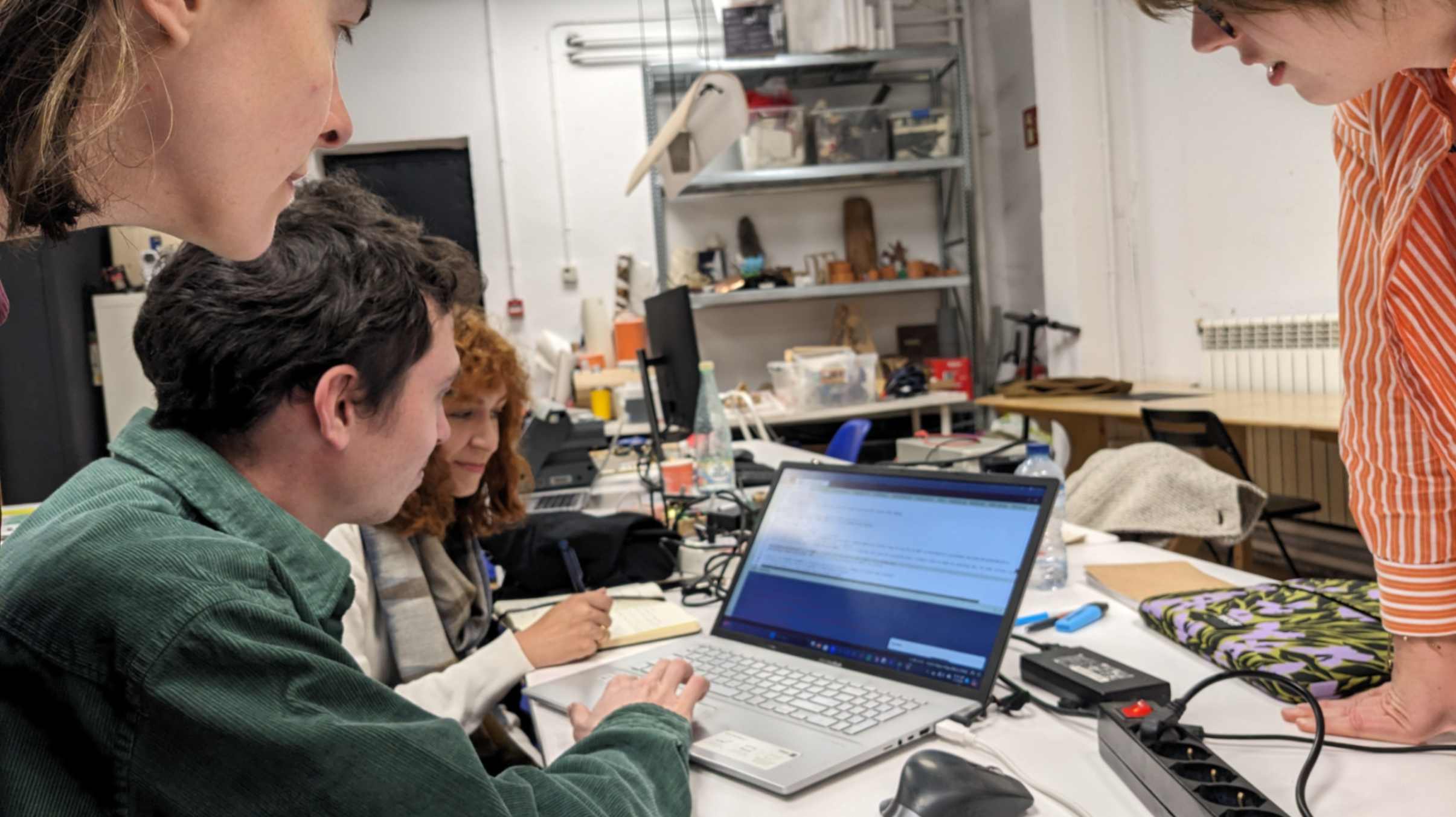
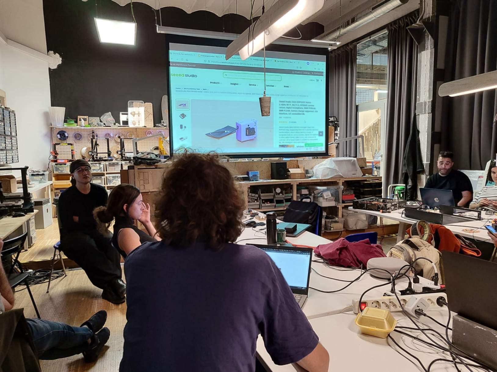
(Project Review with the Fablab BCN team)
At Fab Lab Barcelona, the lab organised a project review in which we presented our final projects to the people in the Fab Lab BCN team. It was a good opportunity to organise the final project and explain to people who have never seen our final projects in a 4-minute presentation. Also, the feedback and references from them were very helpful.
Reference from Project Review

2.1 - 3.0 Python & MediaPipe & Raspberry Pi
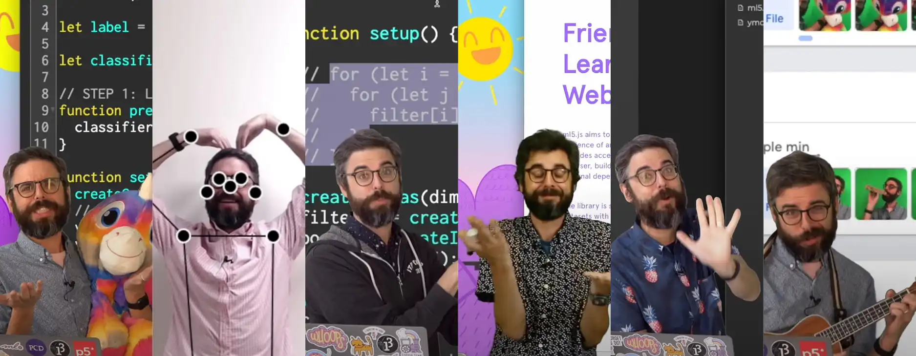
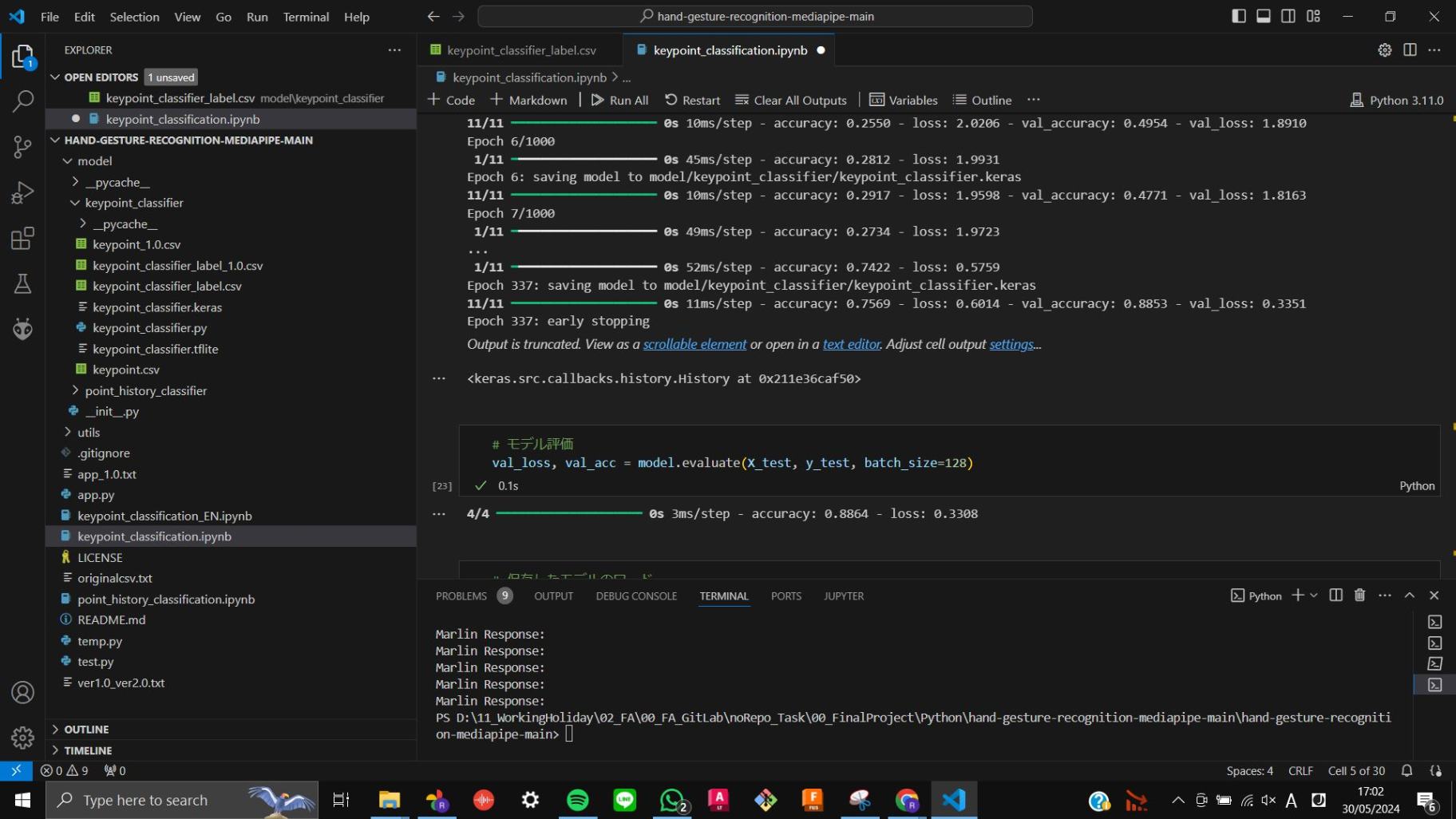
During Week 15 Wildcard, I spent time developing computer vision and machine learning for dancing part of my final project. It was really difficult to play around and took me a long time to develop it. However, with help from my tutor and friends I was able to achieve the goal.
Documentation is on
Week 15 Wildcard
3.1 - 4.0 System Intergratation
During Week 16 System Integration, I took time off from developing the final project and spent time on the packaging, which was a whole other cycle. From this phase, I learned a lot of techniques, such as allocating electronics, reconnecting wires, and powering the system. In the end I was able to integrate all the scattered modules and electronics in a package.
Documentation is on
Week 16 System Integration
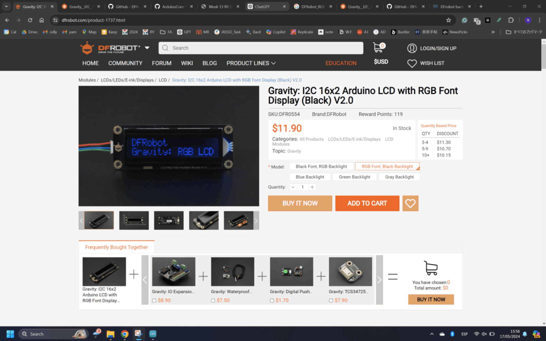
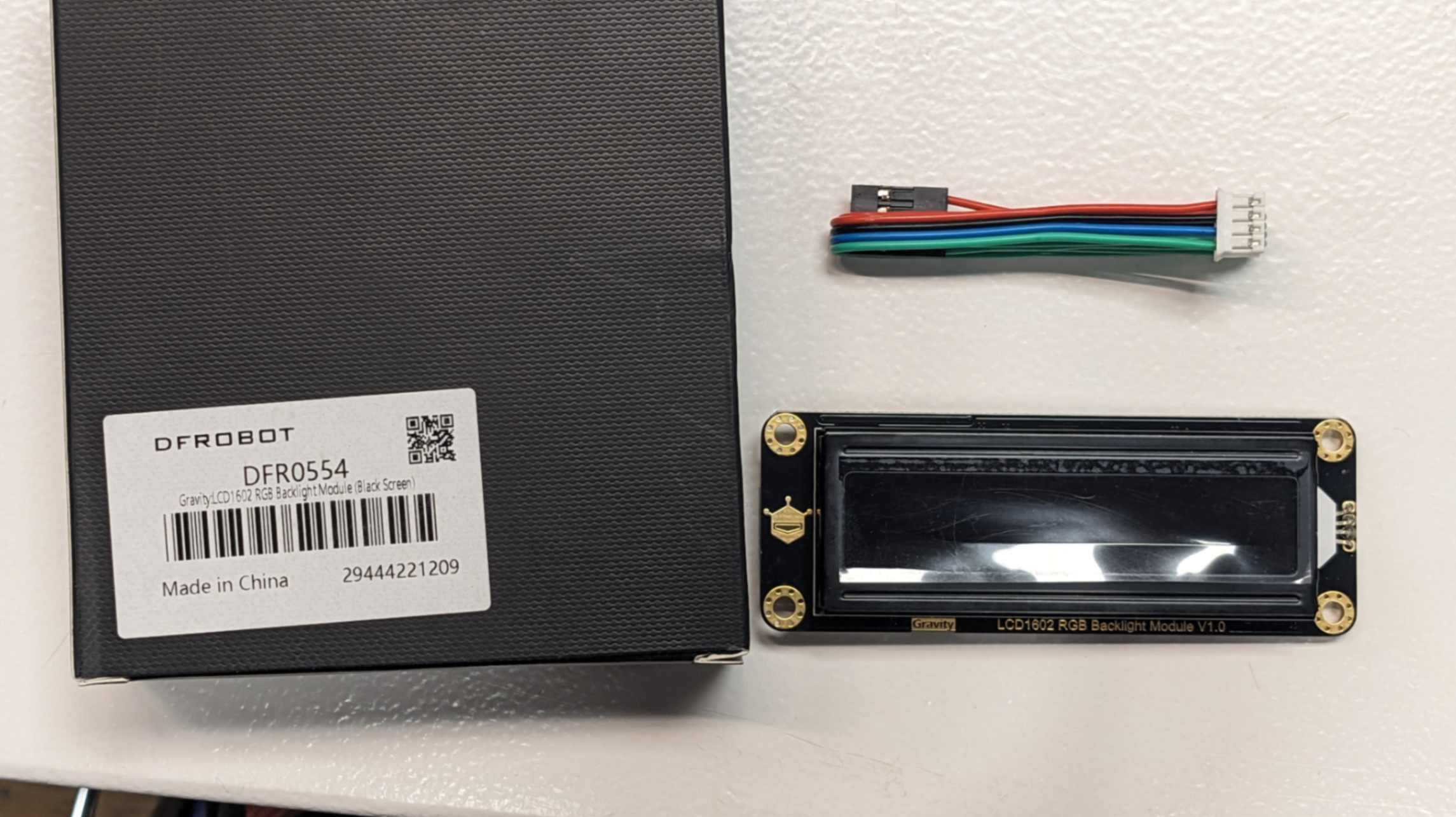
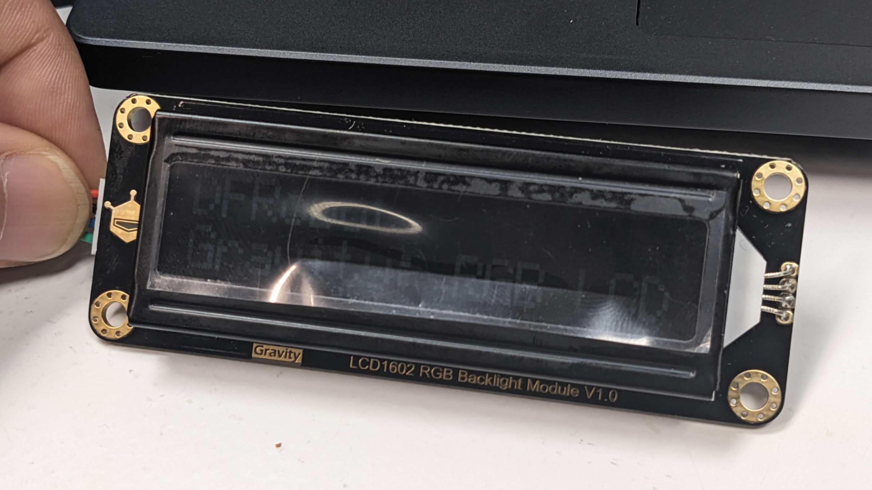
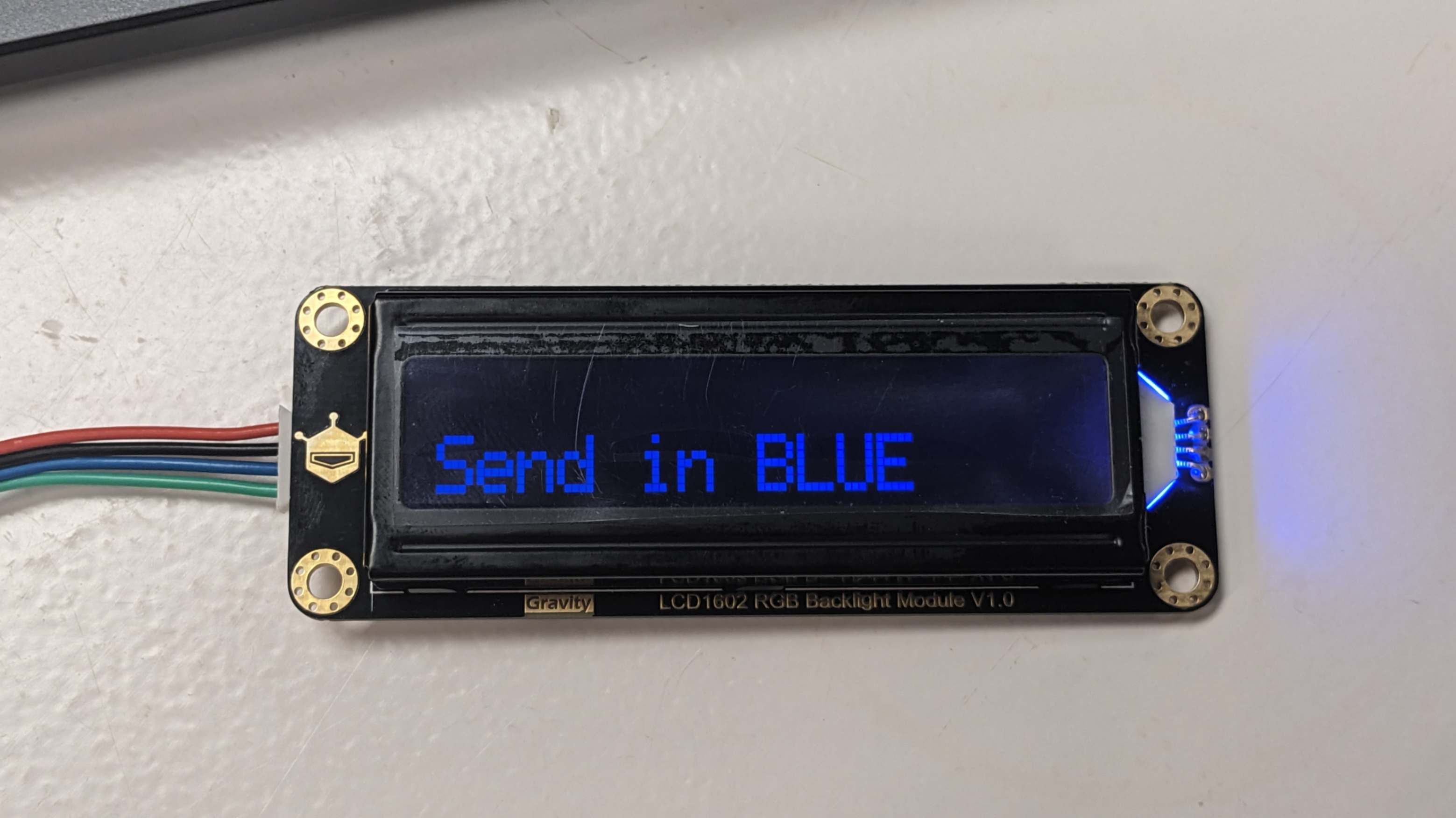
4.1 RGB LCD Screen
After doing the software system diagram I wanted to have a LCD screen for my final project. So I asked my tutor for it he gave me Gravity: I2C 16x2 Arduino LCD with RGB Font Display (Black) V2.0
I followed this official instruction for installing the library.
Then I used example code on
This page
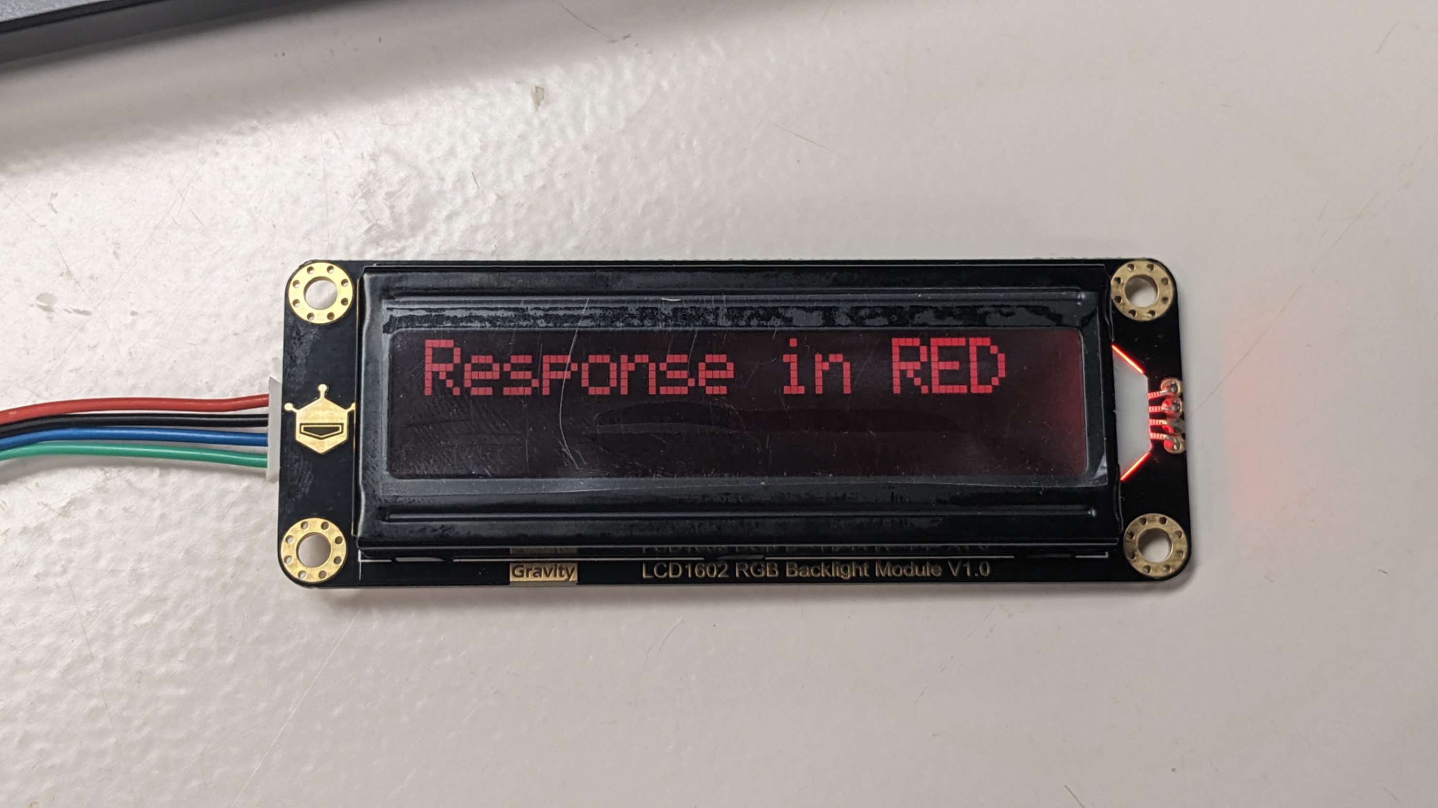
It worked but the backlight was not on.
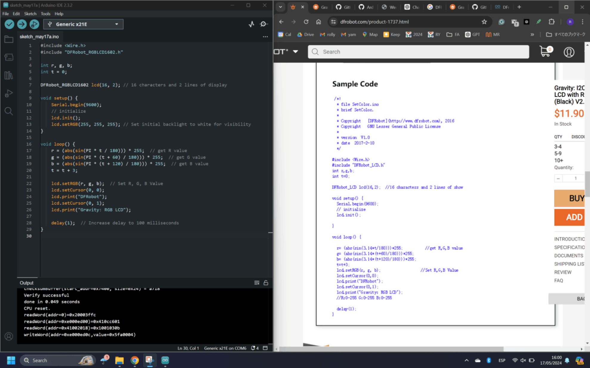
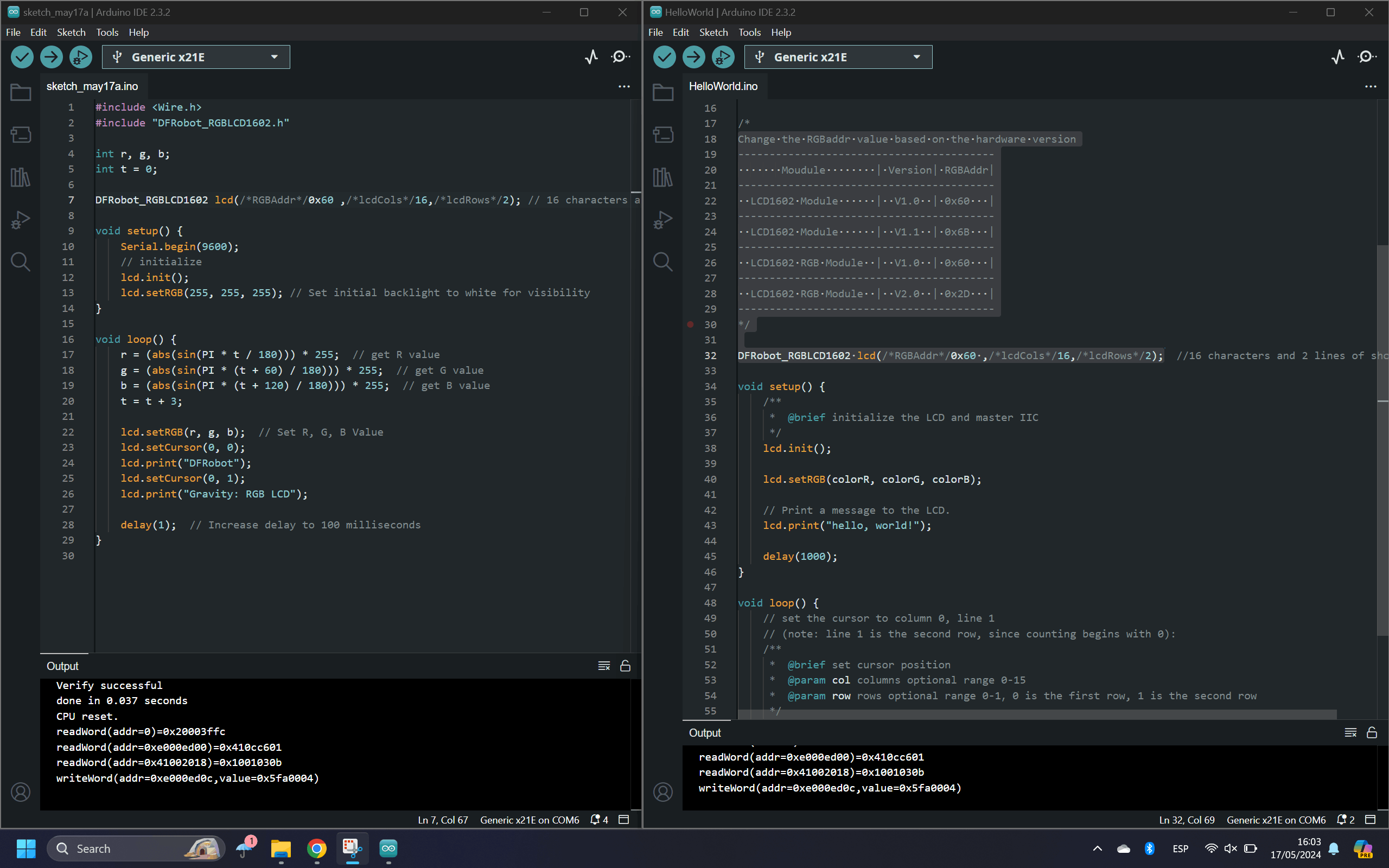
To find out why, I used the example code that came with the Arduino library which worked perfectly. By comparing the two, I realized that the RGBAddr value needed to be specified depending on the module. In my case, it was 0X60. After adding the RGBAddr value the first code worked perfectly.
In order to customize the LCD, my tutor advised me to look at
This documentation page
From this page, lcd.clear(); function to erase the previous letters and other functions.
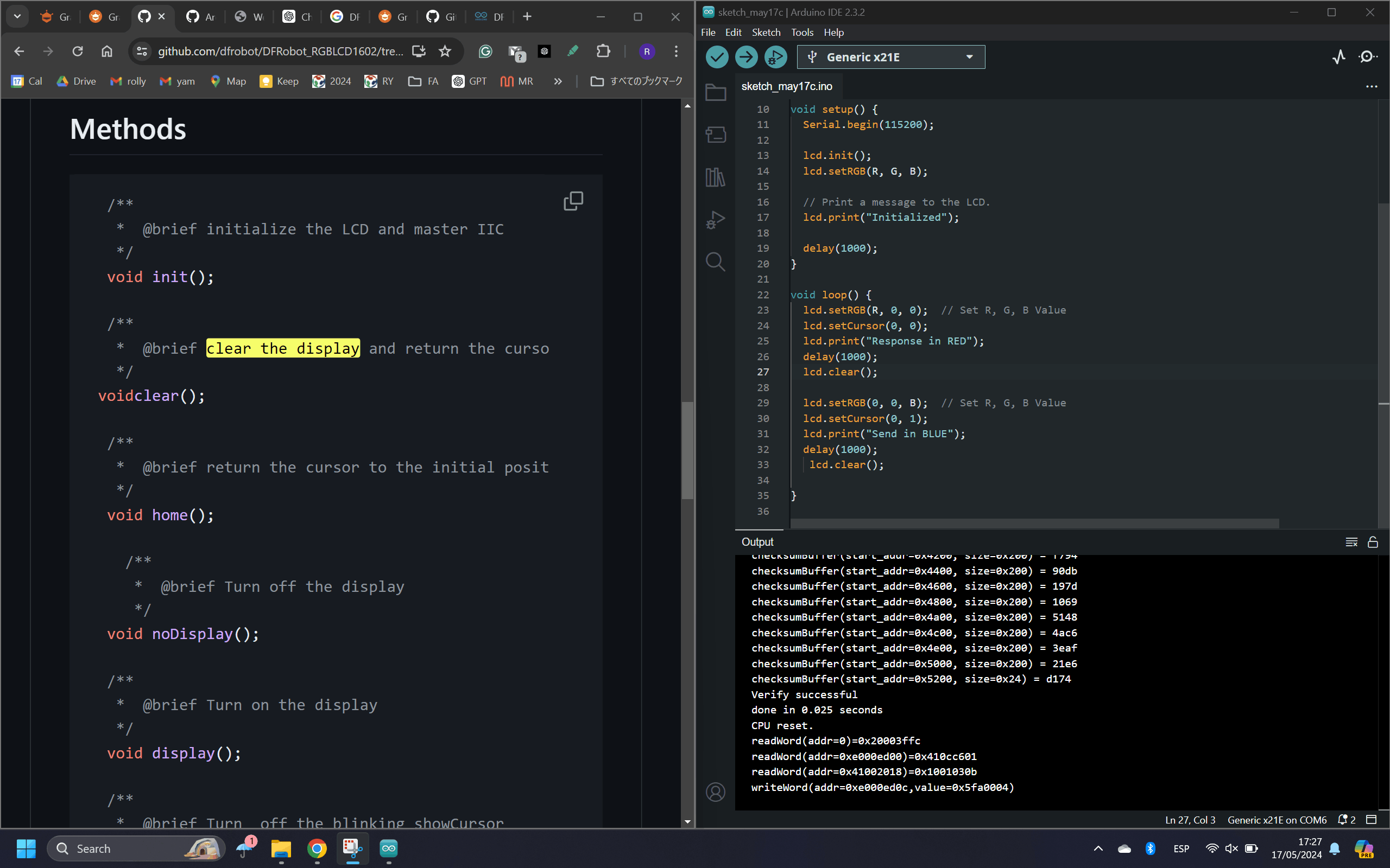
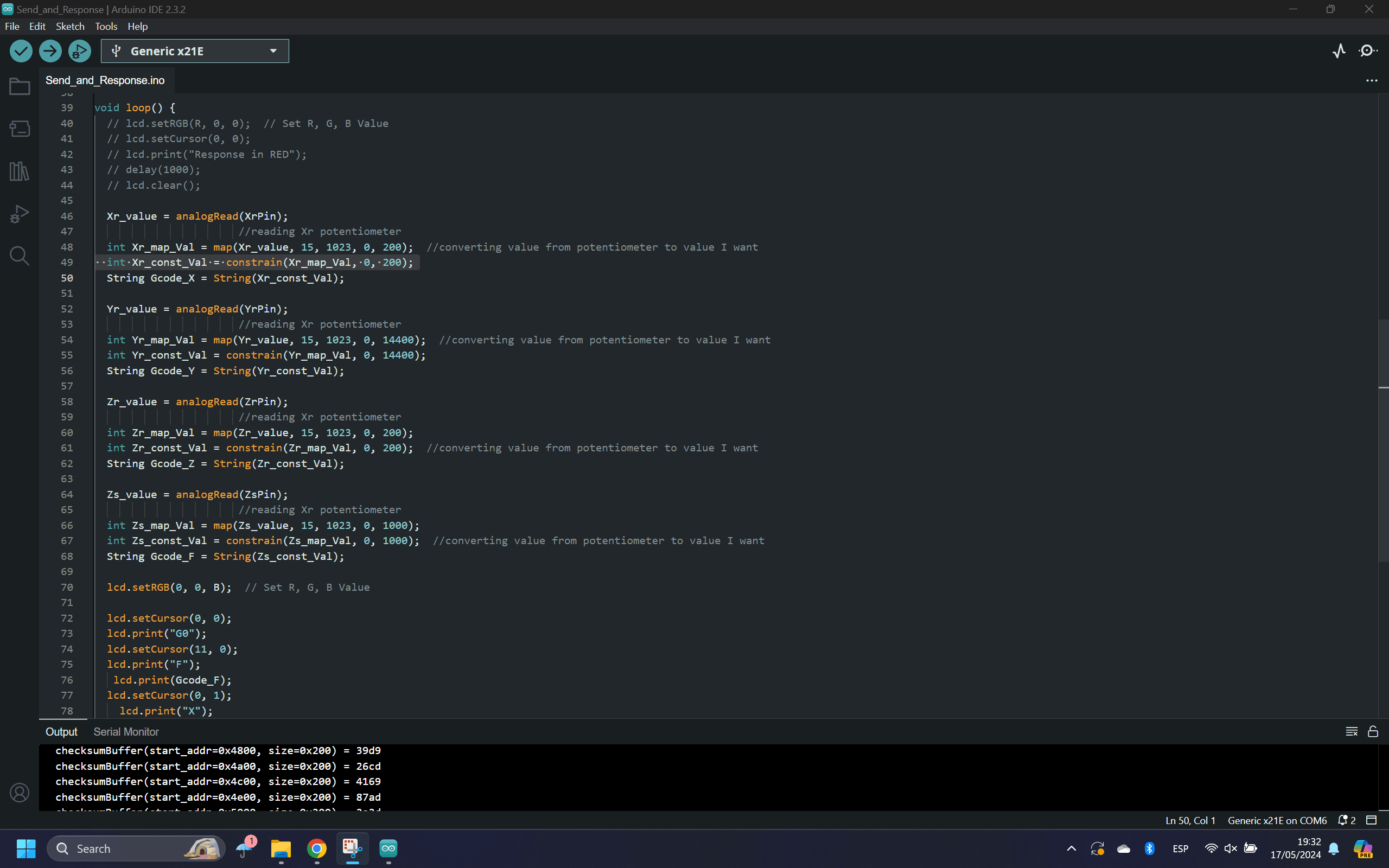
Next, I used a potentiometer to change the value and display them on the LCD. I used an Arduino example as a general reference, and I used code that I wrote previously and combined them together. After all, I was able to write and understand the code almost by myself. One thing I needed help with was to insert a limitation to the potentiometer value in the code. For this, my tutor advised me to look into
constrain()
I looked into This page and I was able to include the function in my code to create a limitation to the value.
4.2 DJ Coding
Since my SAMD21 PCB is the one communicating with different modules and sending Gcode to the 3D Printer, I needed to reprogram it.
It was a very good challenge for me to write a main code in C++ because I can understand the entire function of the machine in one script
To start with, I combined multiple scripts that I had written previously such as
the Code_StepWithoutDelay-Potentiometer-3StepperMotors script
the Potentiometer + Firmware script
the Serial Communication script
the Switch Mode script
RGB LCD script
The Switch Mode script was newly written because I wanted to include a way to have multiple modes to play around with the DJ set. I used
This page
to get a quick understanding of how the switch functions.
For physical components, I grabbed a slide switch
(R13-608A1-02-BB-9A)
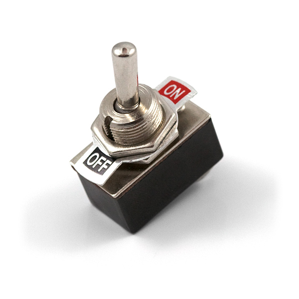
and a toggle switch
(COM-09276)
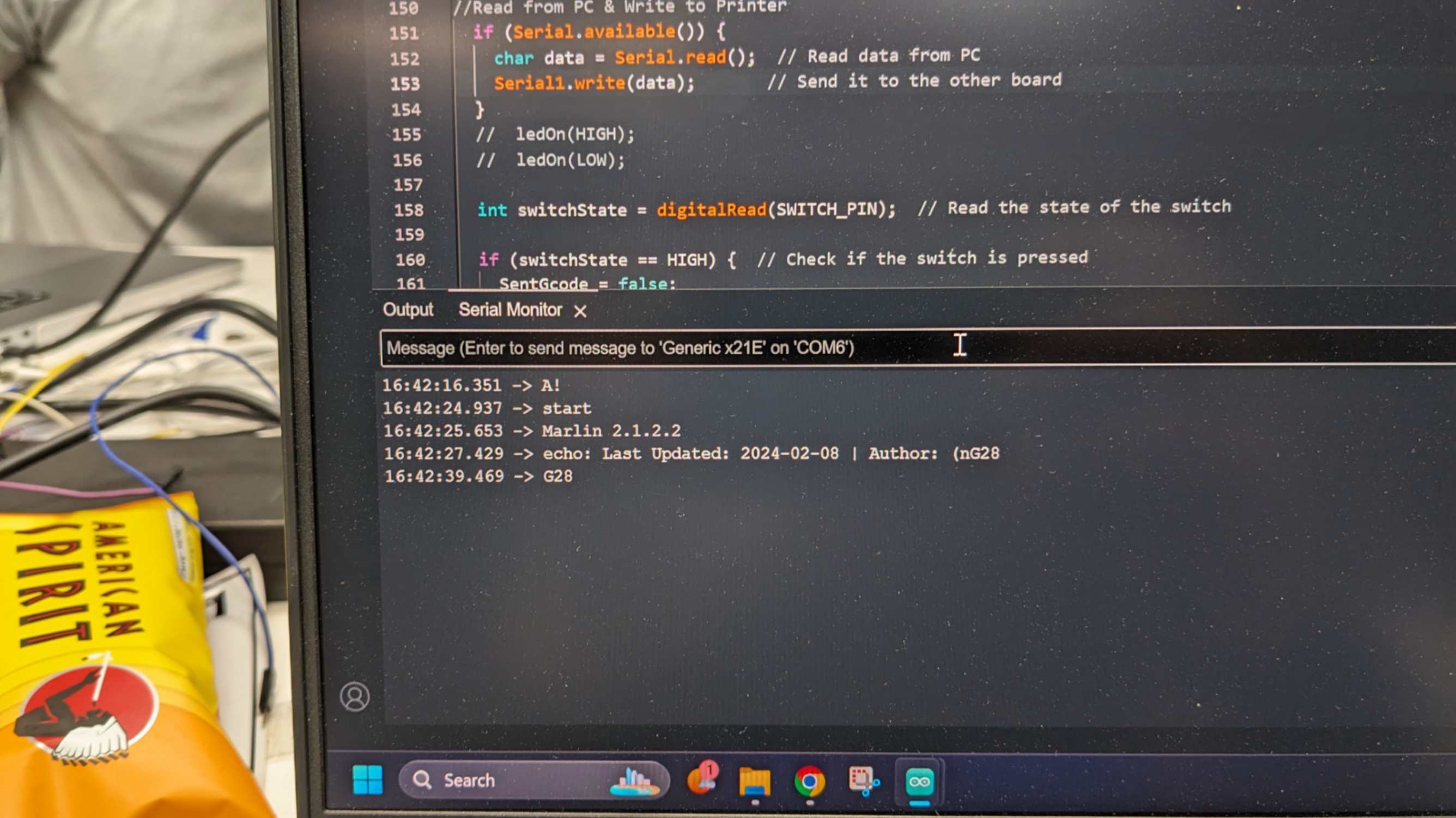
The Switch code is fairly simple because it just reads the switch state and runs the rest of the code according to whether the switch is ON or OFF (HIGH or LOW)
After combining these multiple scripts, I also added boolean functions for some parts of the script to run once or only in certain scenarios. The difference between a boolean and an int is that a boolean is only true or false, whereas an int can be anything. It was a very useful command especially when I wanted to run some part of the code in certain order. Also I used This page to help me understand this function.
      //in the setup
      boolean Myfunction = false;

      //in the loop
      if (Myfunction == false){
      Serial.print(“Hello World”);
      Myfunction == true;
      }
After writing the main script for a while, the script got very long and complex to the point where I had difficulty explaining the code to my tutor. Then my tutor advised me to declare functions separately and call those functions in the main loop, so it looks cleaner and easier to follow. One thing to be careful of is that whatever is inside the void function needs to be declared before the void setup.
      //in the loop
      functionname();

      //after the loop
      void functionname() {
      //function code
      }
Also, I learned the way to have multiple conditions for the if statement. This learning allowed me to make more brunches in the script.
      if (condition A && condition B) //this means A and B
      if (condition A || condition B)  //this means A or B
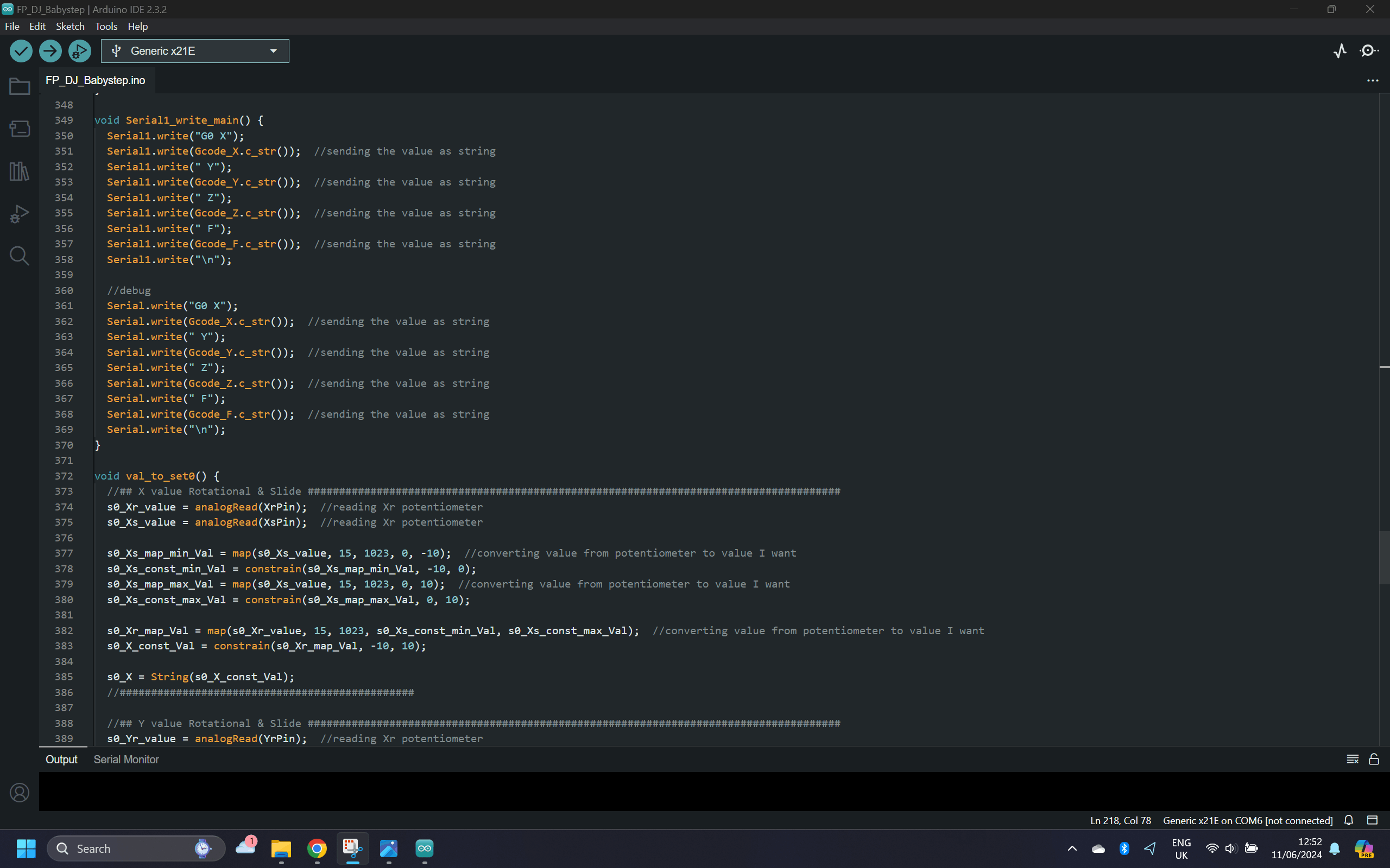
Another useful learning is to use the map() function multiple times for a value. I mapped a slider potentiometer value to select the minimum value and the maximum value. for A and then mapped a rotary potentiometer value to select A value between the minimum value and the maximum value.
      val_slider = analogRead(sliderpin);
      min_val = map(val_slider, 15, 1023, 0, -10);
      max_val = map(val_slider, 15, 1023, 0, 10);

      val_rotary = analogRead(rotarypin);
      val_A = map(val_rotary, 15, 1023, min_val, max_val);
My tutor advised me to add a function to guide me to set the potentiometer to 0. So when I change from Gcode mode to Babystep mode, I can make sure the potentiometer value always starts from 0.
This is the result.
4.3 Subtractive Manufacturing
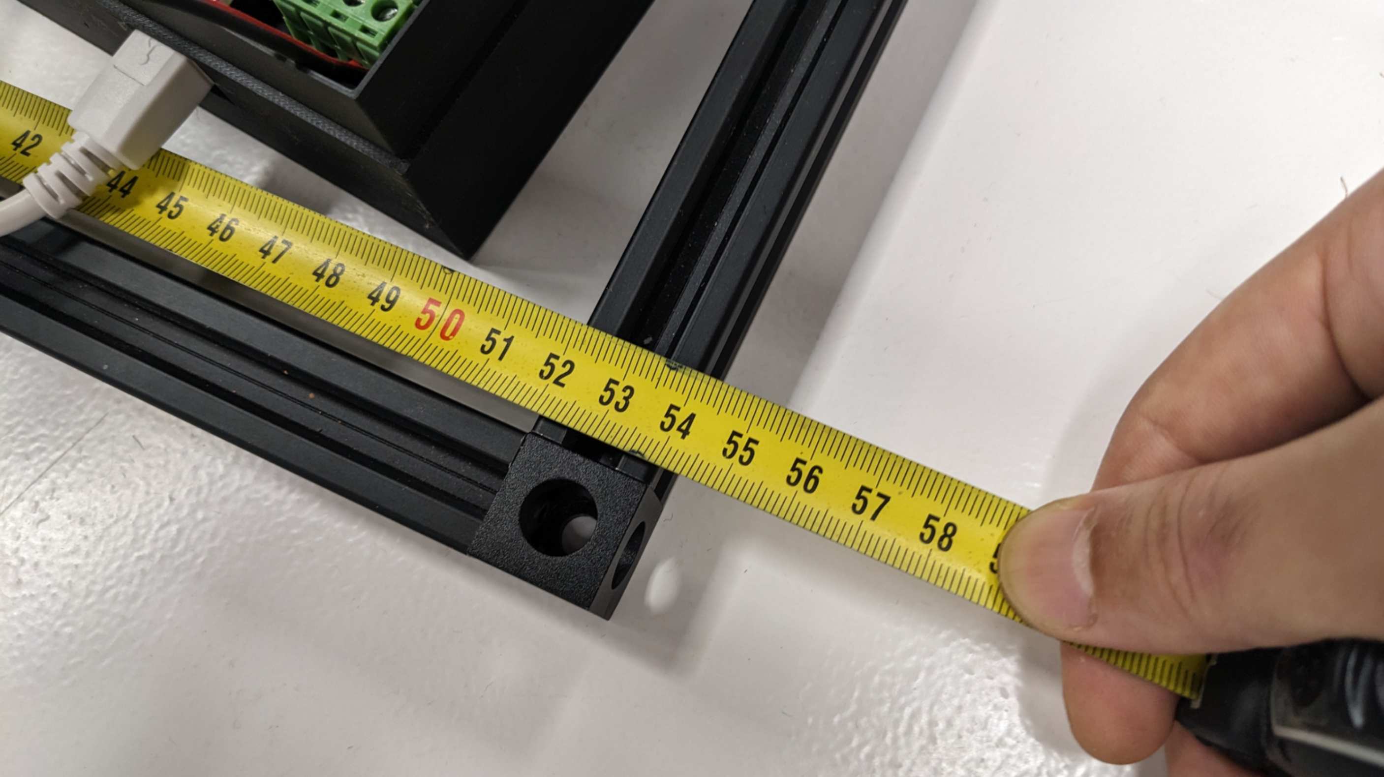
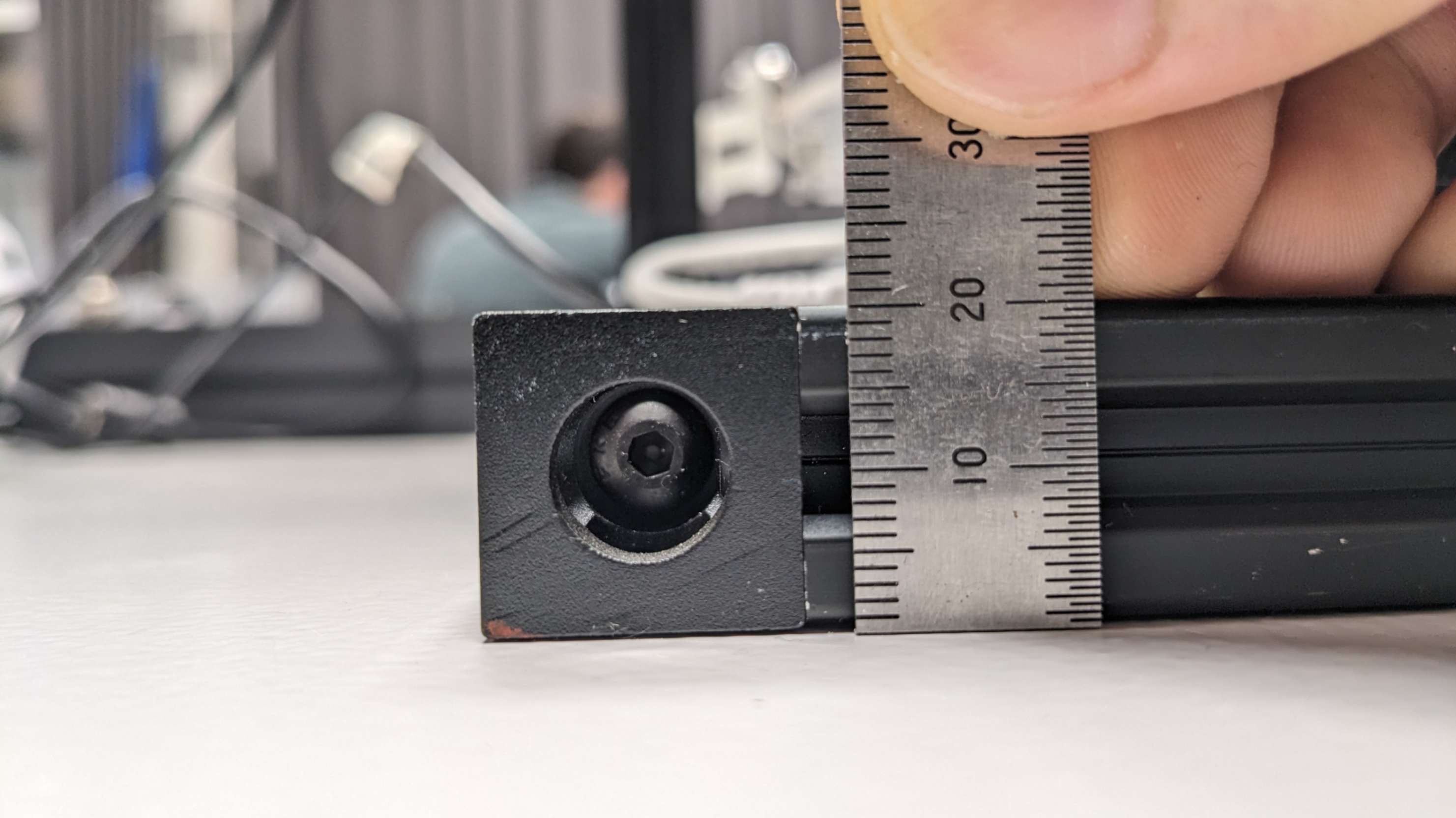
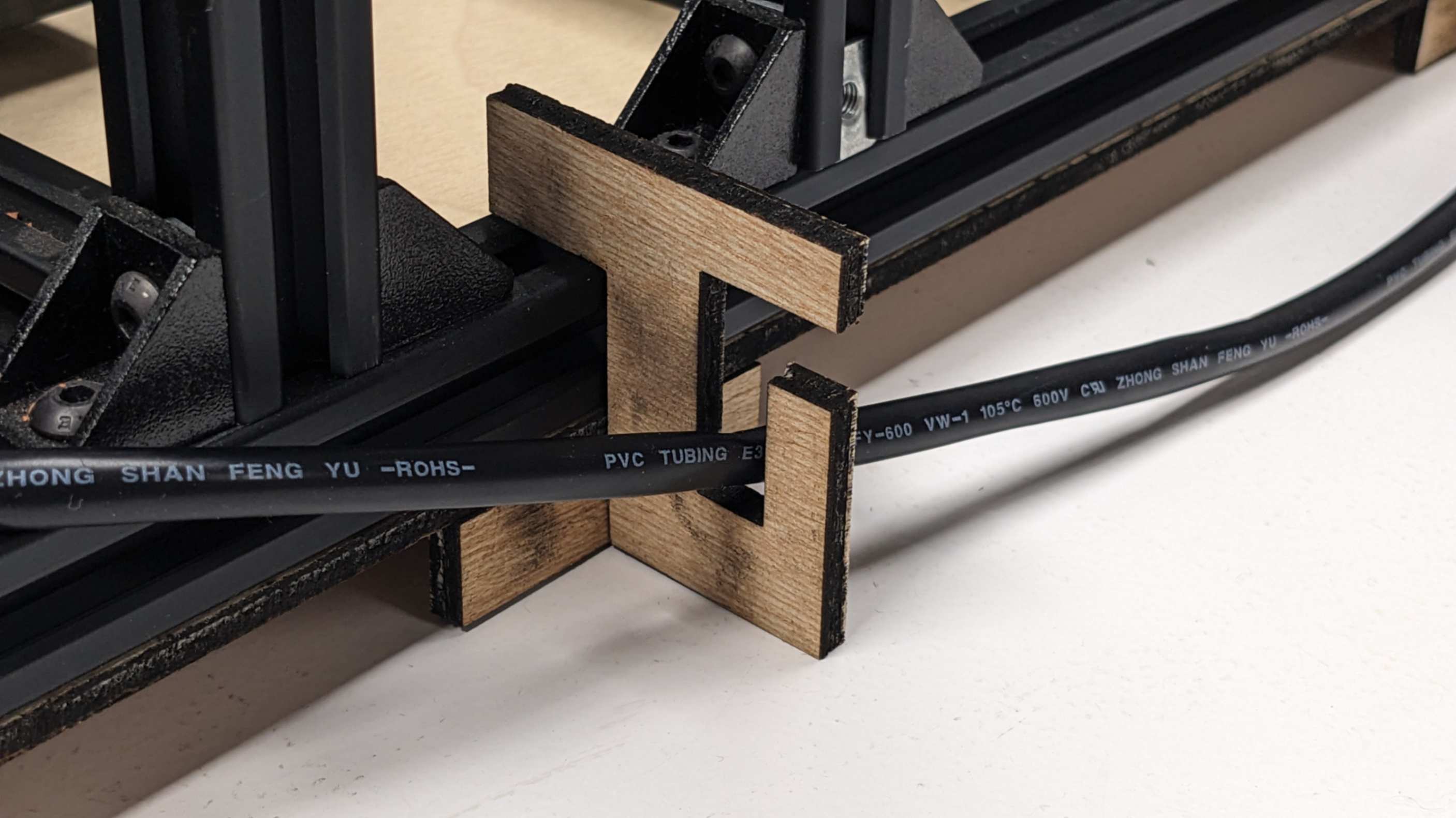
As one of the requirements for the final project, I needed to use a subtractive manufacturing technique which I have not used yet. For this task, I decided to laser-cut a base plate for the 3d printer so that I could easily carry all the devices attached together without the need of plugging and unplugging the wires which sometimes causes some issues.
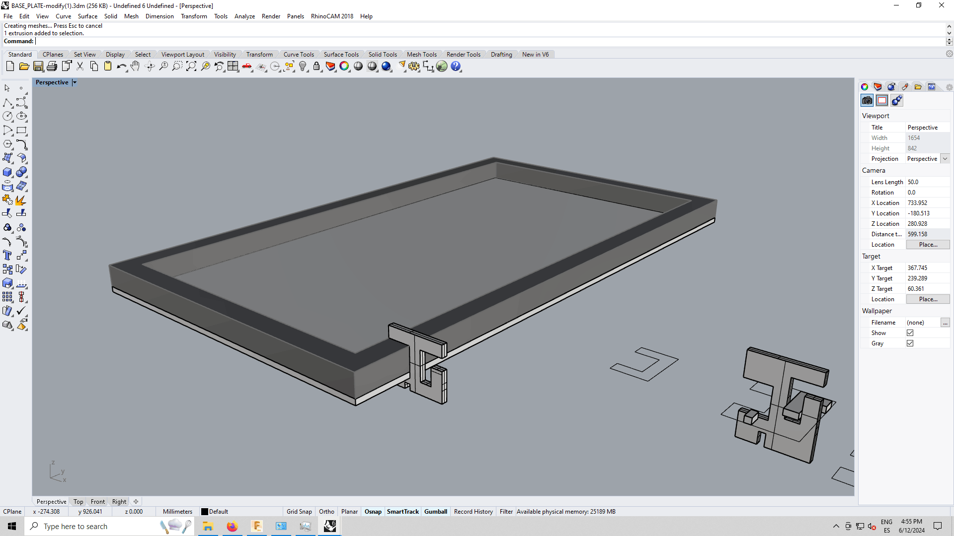
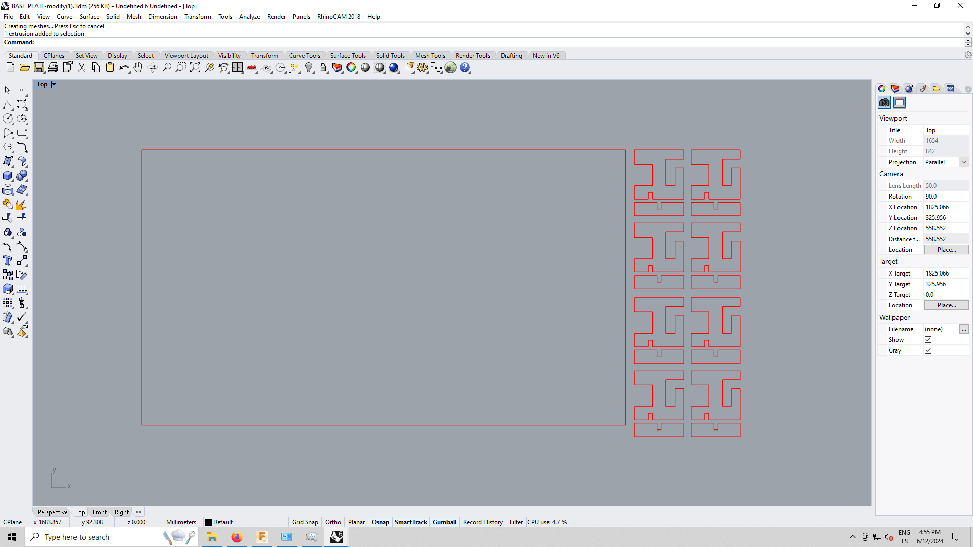
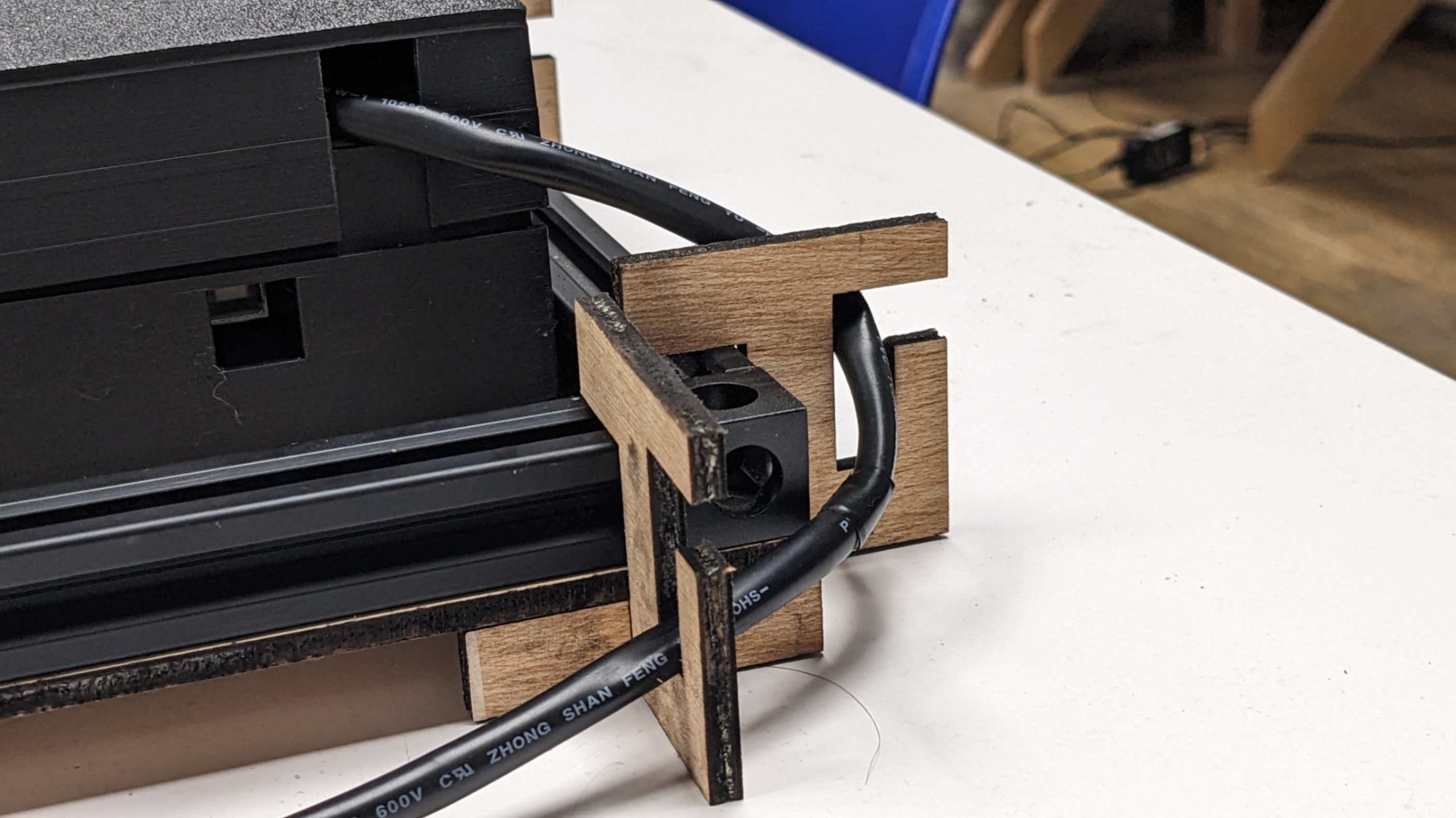
First I took measurements of the bottom frame of the printer then I made a 3D model in Rhino. To attach the base plate to the bottom frame I needed to make something to hold them together. I made a very simple slot-in joint part with the capability to hold some wires on the other side. For cutting material I used 5mm plywood.
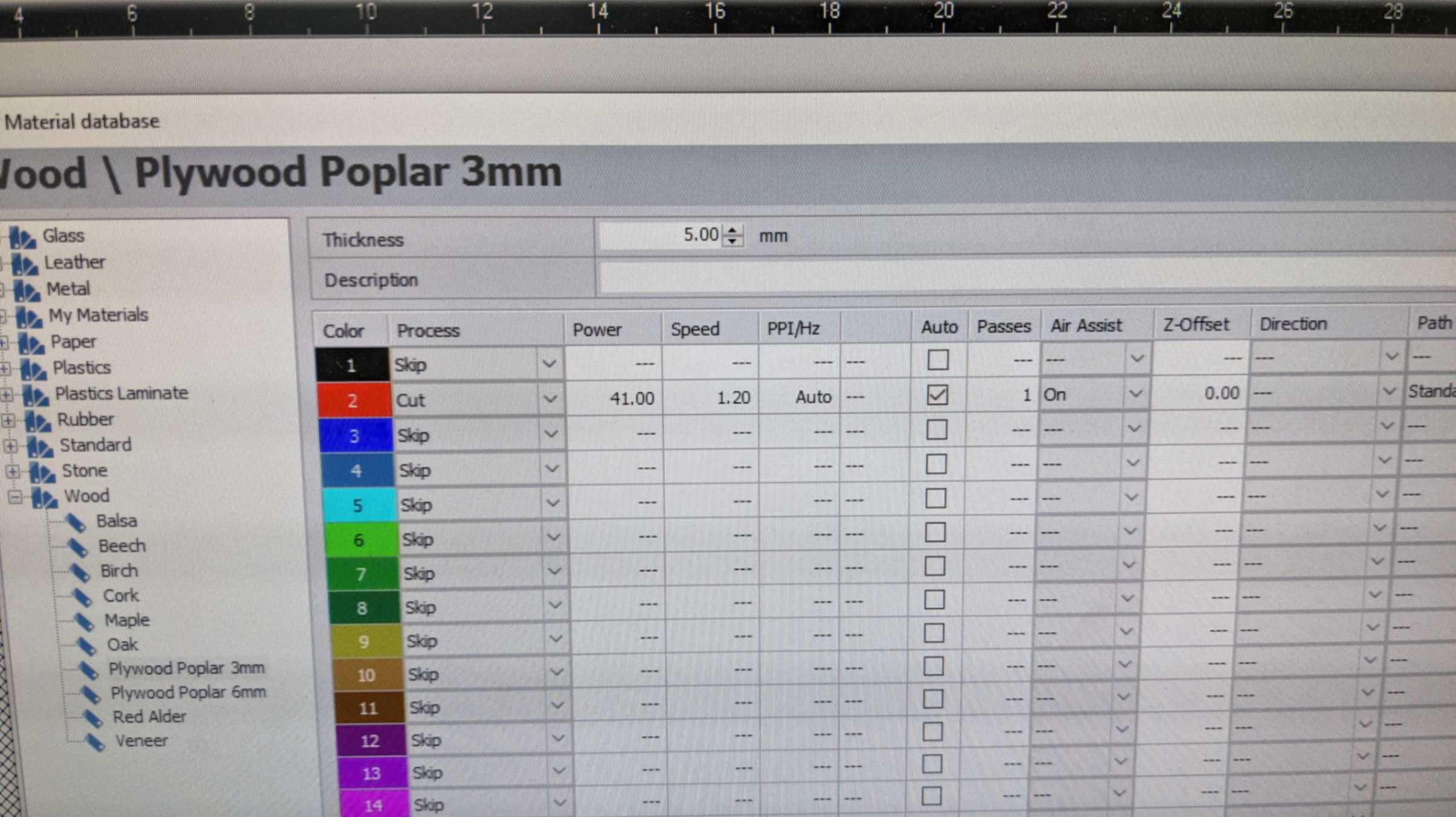
The laser-cutting process was rather hard because I could only use a machine that I had not used in the previous week. The machine was
Rayjet R400
After much trial and error, I settled with this setting, Power 41.00 and Speed 1.20.
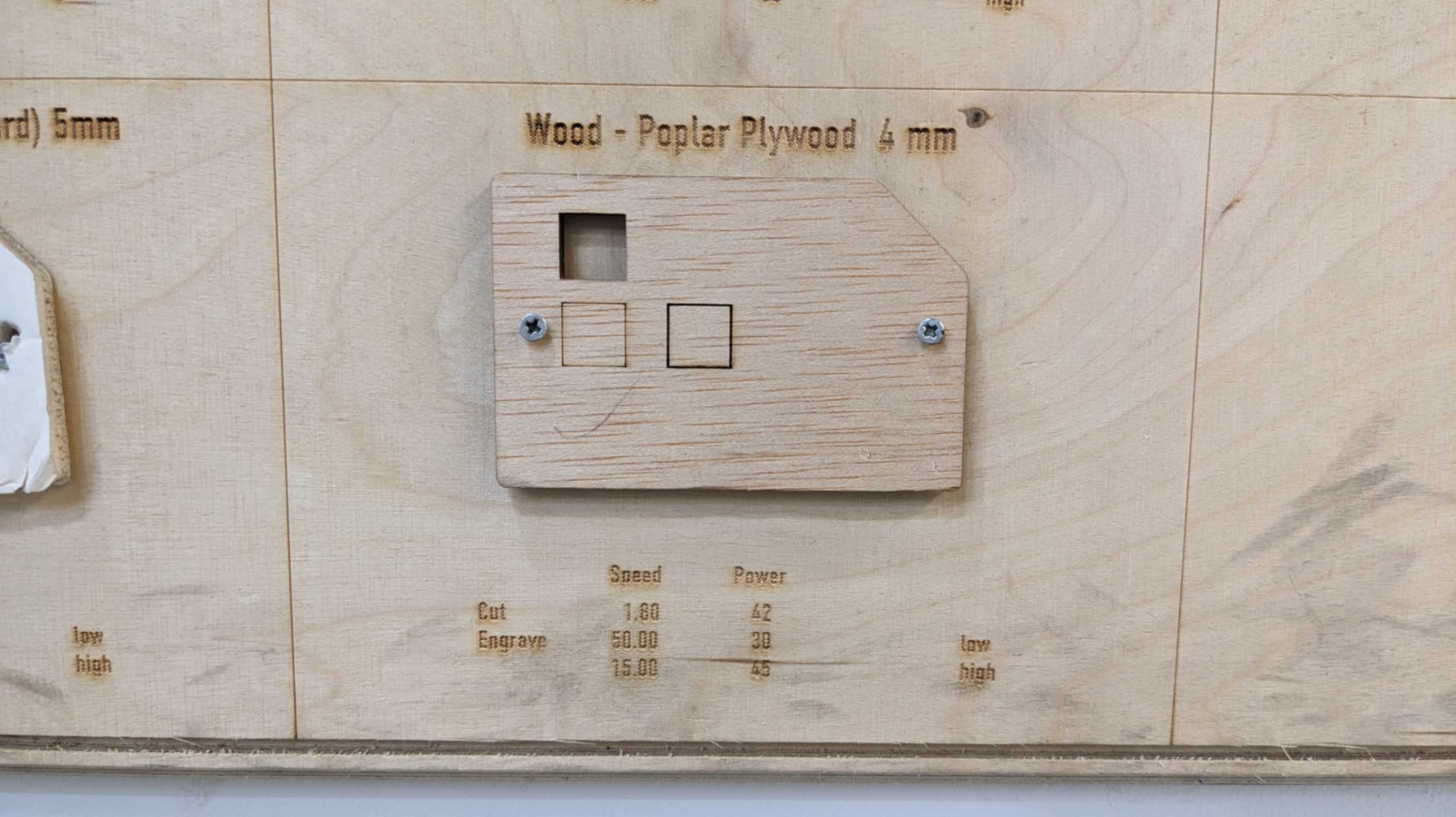
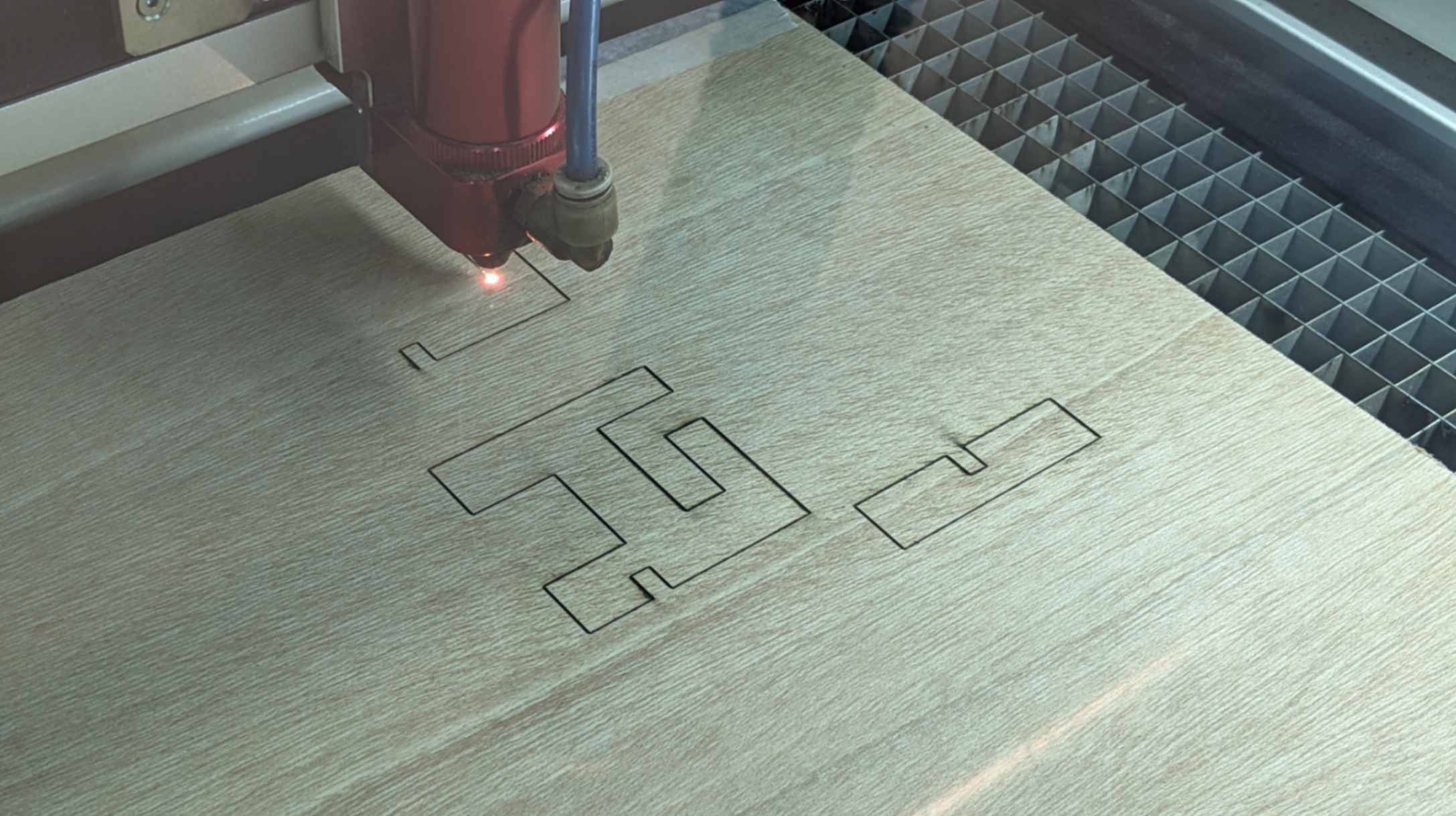
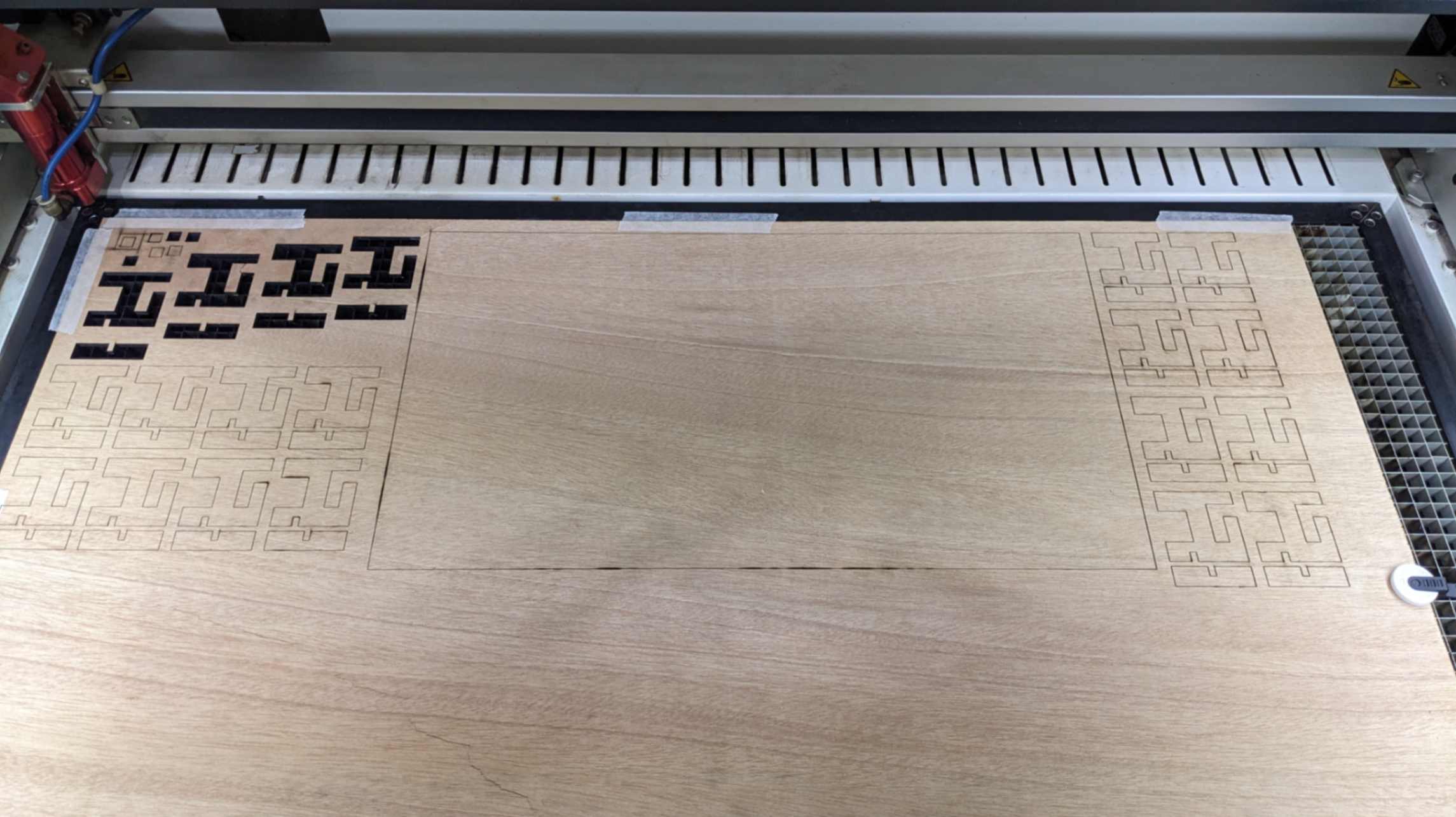
The result was not perfect because the cut edge was burned too much. Although it works as a base plate and holds wires so I am ok with that. I decided to move on to the next step of my project.
4.4 Final Adjustment
GND, TX, RX
The serial communication between ArduinoMega and SAMD21 board had some issues that I did not what was causing it. It was working but sometimes act weirdly and sometimes it did not work. The serial communication seemed unstable and rugged for some reason.
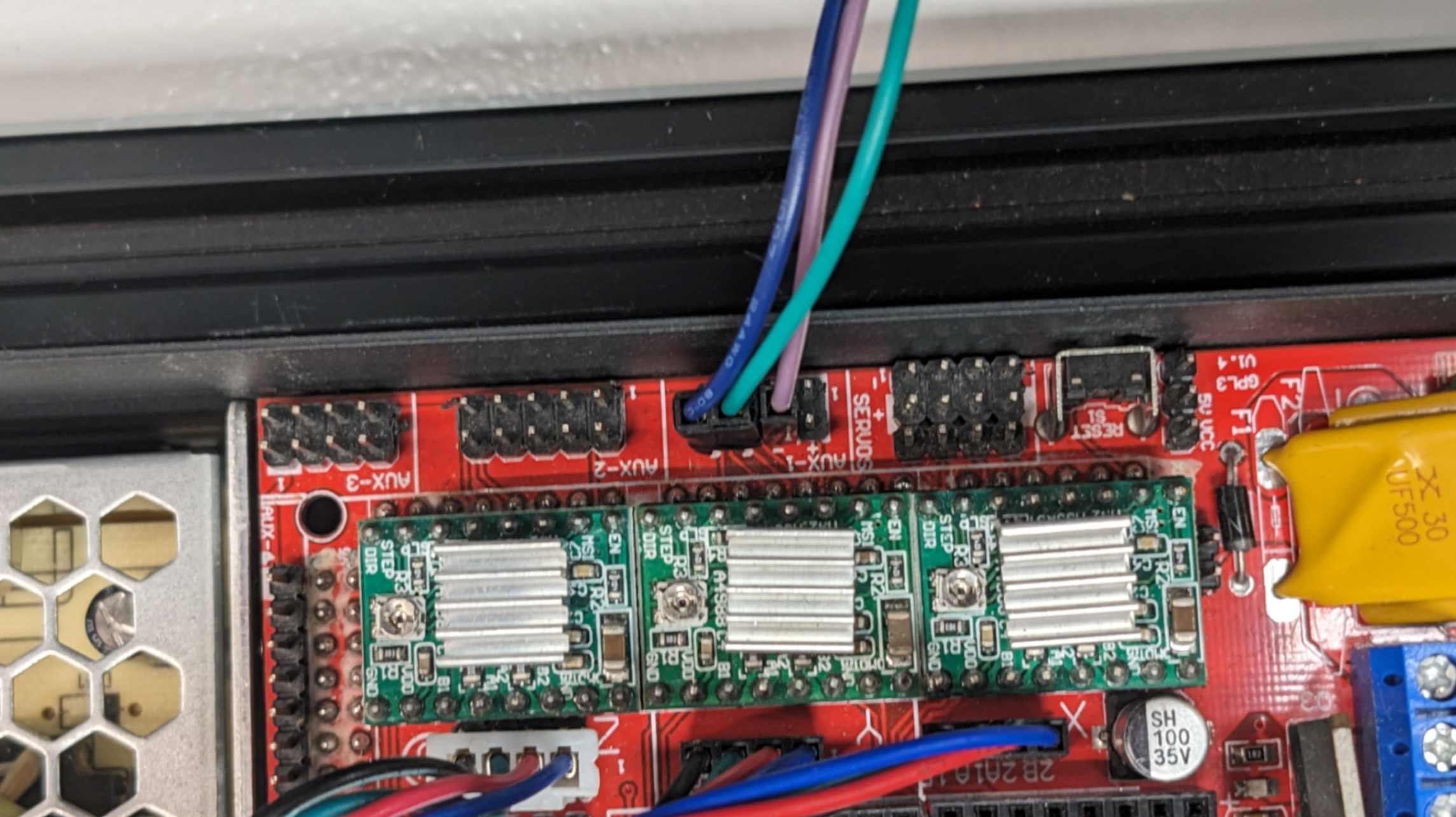
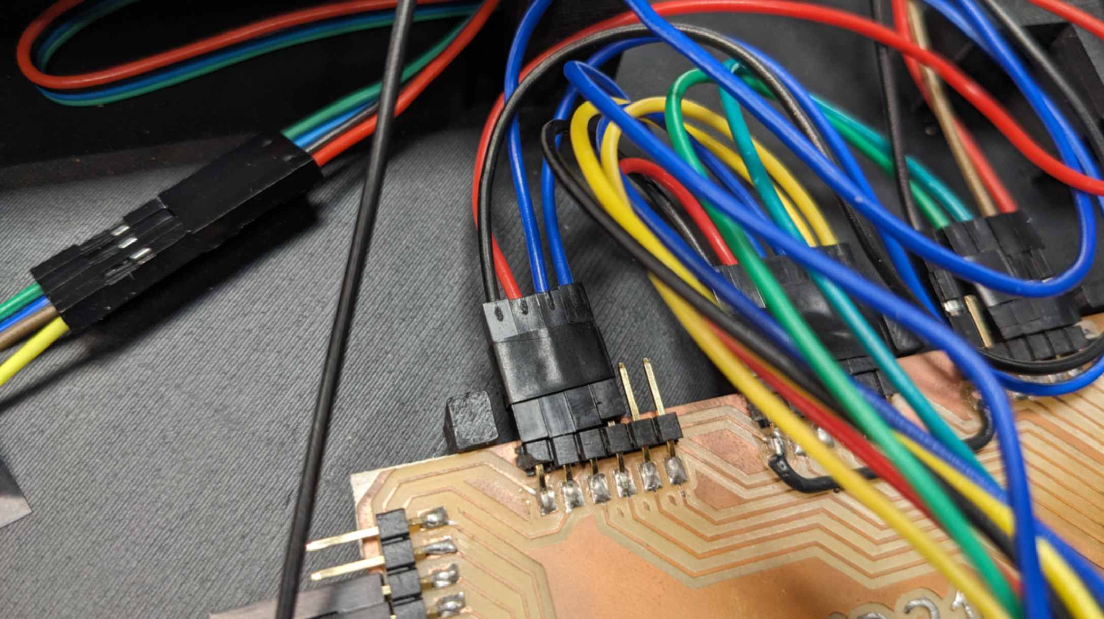
Then my tutor Mikel told me to see if connecting GND helps or not. I took his advice and connected GND with a purple wire, then suddenly it was working as it was supposed to. From this, I learned the importance of sharing the common GND and always connecting GND, which I heard many times throughout Fab Academy.
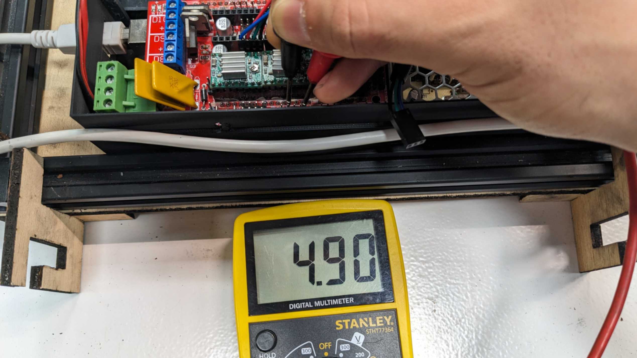
5V issue
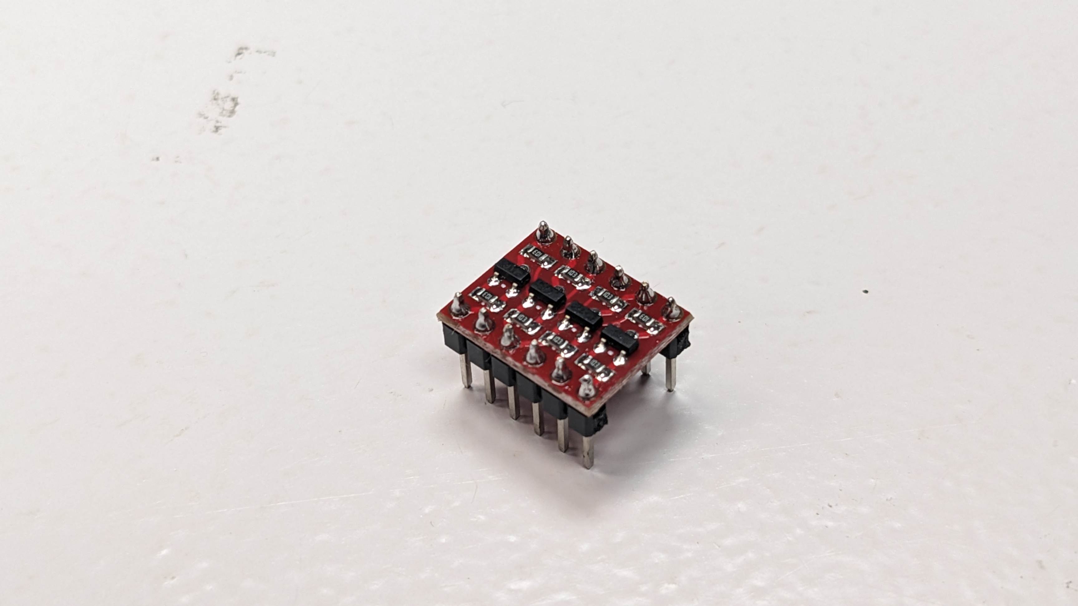
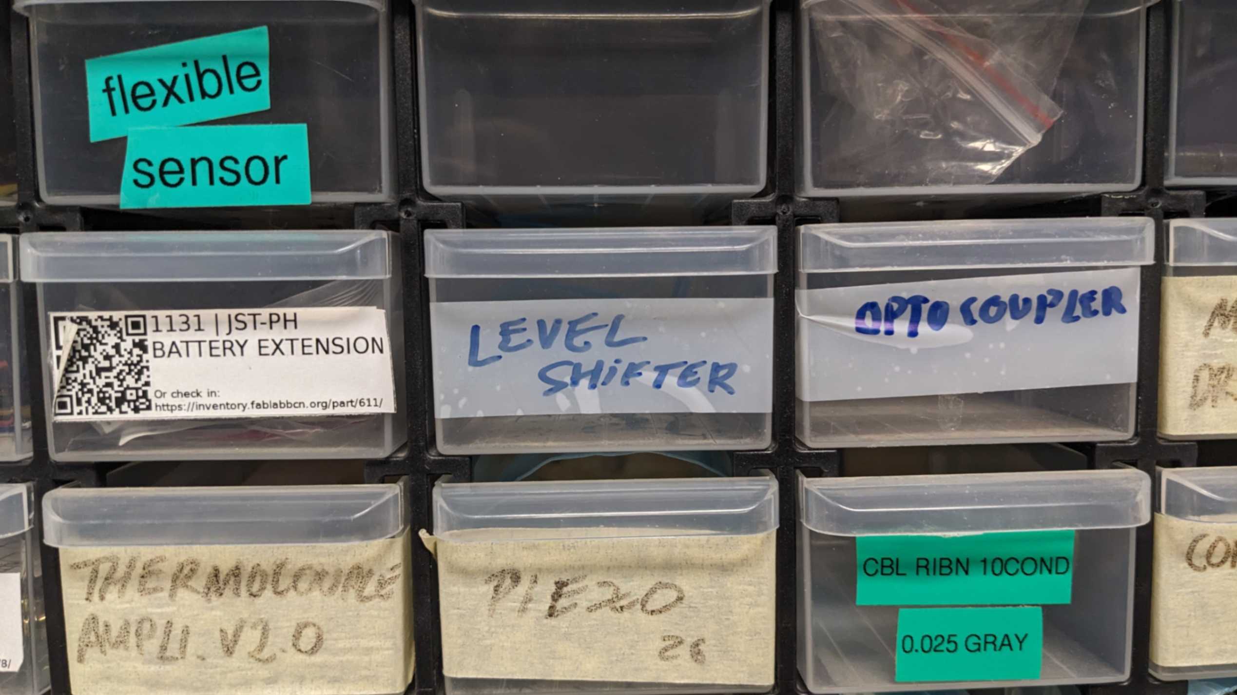
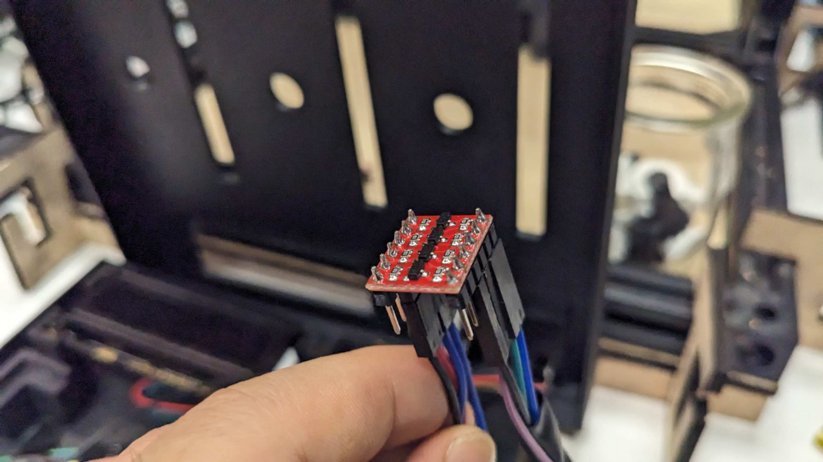
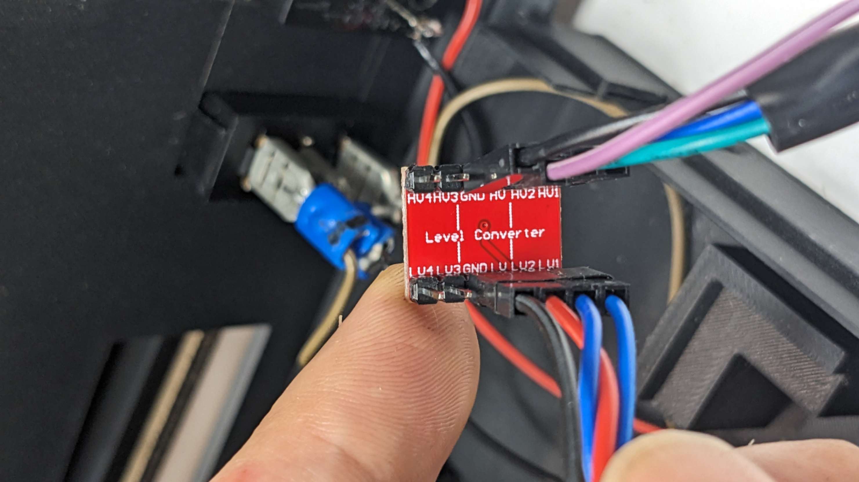
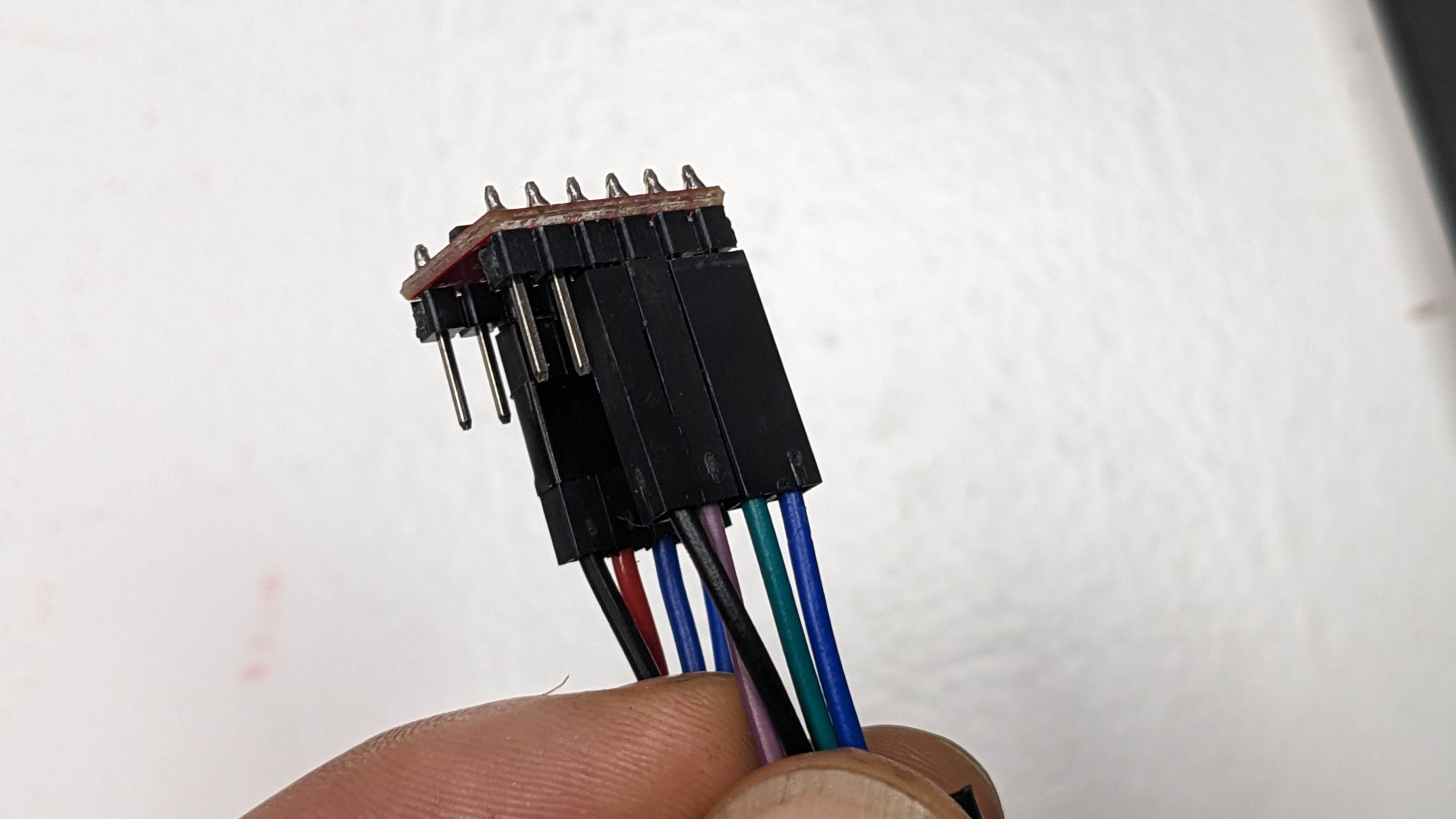
This is something my tutor Josep found out. My SAMD21 PCB was somehow getting 5V from Arduinomega through RX and TX pins. This explains a lot about some unusual behaviour that the board was having from time to time. Then my tutor advised me to use level converter
This component converts 5V to 3.3V very easily. I connected the level converter with 5V, GND, TX, and RX on the Arduino Mega side, and connected 3.3V, GND, RX, and TX on the SAMD21 side. As a result, the serial communication was a lot more stable and I did not experience any weird behaviour after this change.
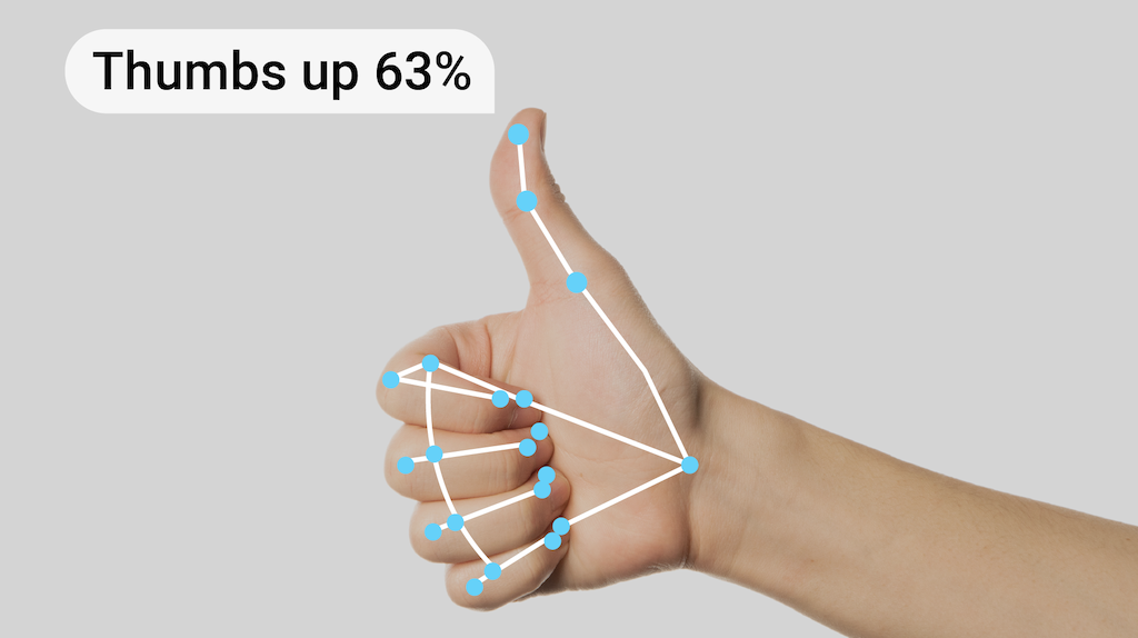
Re-Machine Learning
Since I included the DJ set in my final project, I no longer needed to control all the necessary functions by gesture recognition. For example, homing(G28), centering (G0 X0 Y0 Z0). So I decided to train the model again to detect gestures only for Babystepping. The workflow is exactly the same as I explained before in Week 15 Wildcard week
This time I only trained 7 gestures such as below.
Open Hands up = M290 Z10
Open Hands down = M290 Z-10
Open Hands right = M290 X10
Open Hands left = M290 X-10
Open Hands right = M290 X10
Shaka front = M290 Y10
Shaka back = M290 Y-10
Thumbs up = Thank You
Marlin Y axis
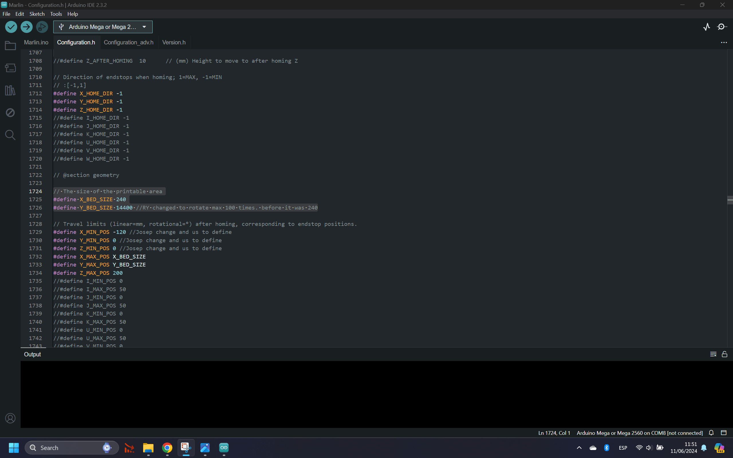
As I was testing my 3D printer to make sure everything worked together and training myself to dance with the machine, I realized that the Y-axis rotational bed was not rotating according to that Gcode I sent. Then I checked the problem by sending a different Gcode. I found out that the Y-axis only rotates for 2 twice. Then I realized that in Marlin Configuration Y axis bed size was defined as 240. This means that the machine thinks it is over the bed size when the Gcode for the Y axis is more than 240, even though it doesn't matter in the case of a rotational bed,
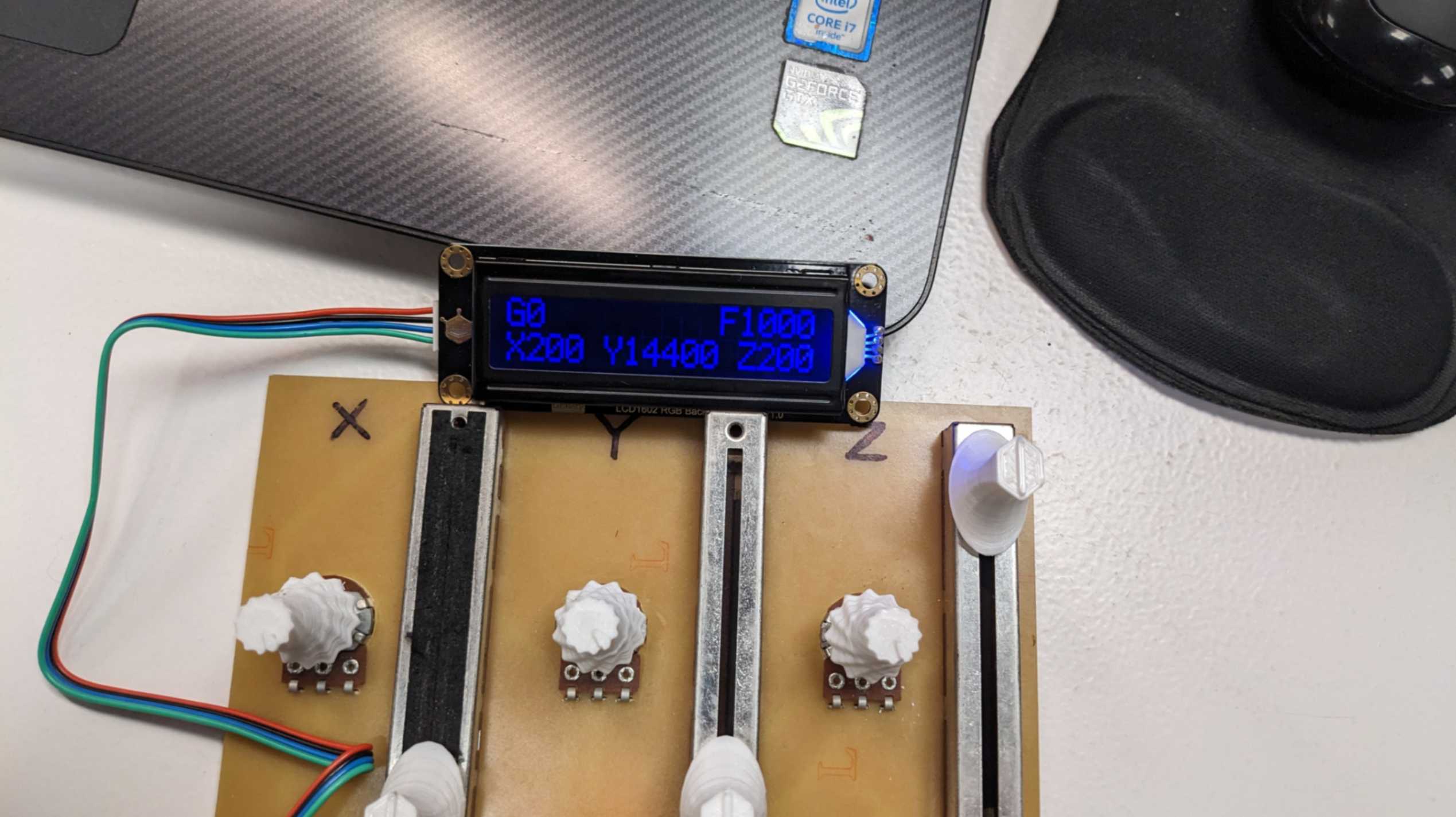
So I changed Y_BED_SIZE to 14400 which allows the Y-axis rotational bed to rotate up to 100 times.
5.0 Presentation
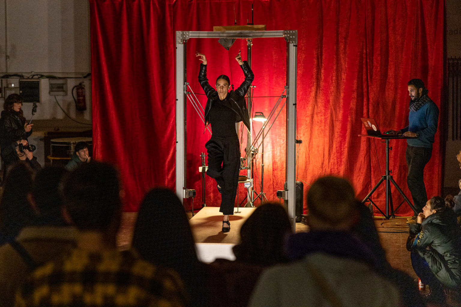
1 min Video
For making the 1-minute final presentation video, I recorded 3 videos (DJ, Dance, Print) at the same time and added another clip that shows the entire performance of me dancing with the 3D printer. It was a really difficult decision-making process to reduce the video to 1 minute.
I used Premier Pro since I have done some video editing with it before. The song I used to dance with the 3D printer was generated by me and Suno AI
I decided to do a voice-over to explain the motivation for the project so that there would not be any difficulty turning on and off the volume on the presentation day.
Compression
To compress the size of the video I used
this youtube tutorial
However, when I uploaded the video it did not play in Firefox but played in Chrome and Edge. Since Firefox is the one used for reviewing the final presentation I needed to change my encoding.
To do this, I used FFmpeg with help from my tutor Josep.
FFmpeg is something we got introduced in Week 2 Computer-Aided Design
Niel prepared a page for HTML5 MP4 ffmpeg encoding Which I used for this task.
Also, my classmate Max shared the code he used to compress his video.
ffmpeg -i "Presentation Final Project.mp4" -vcodec libx264 -preset veryslow -crf 30 "Presentation.mp4"
Alternatively, I could use HandBrake Which does the same thing but with a user interface.
Project Management
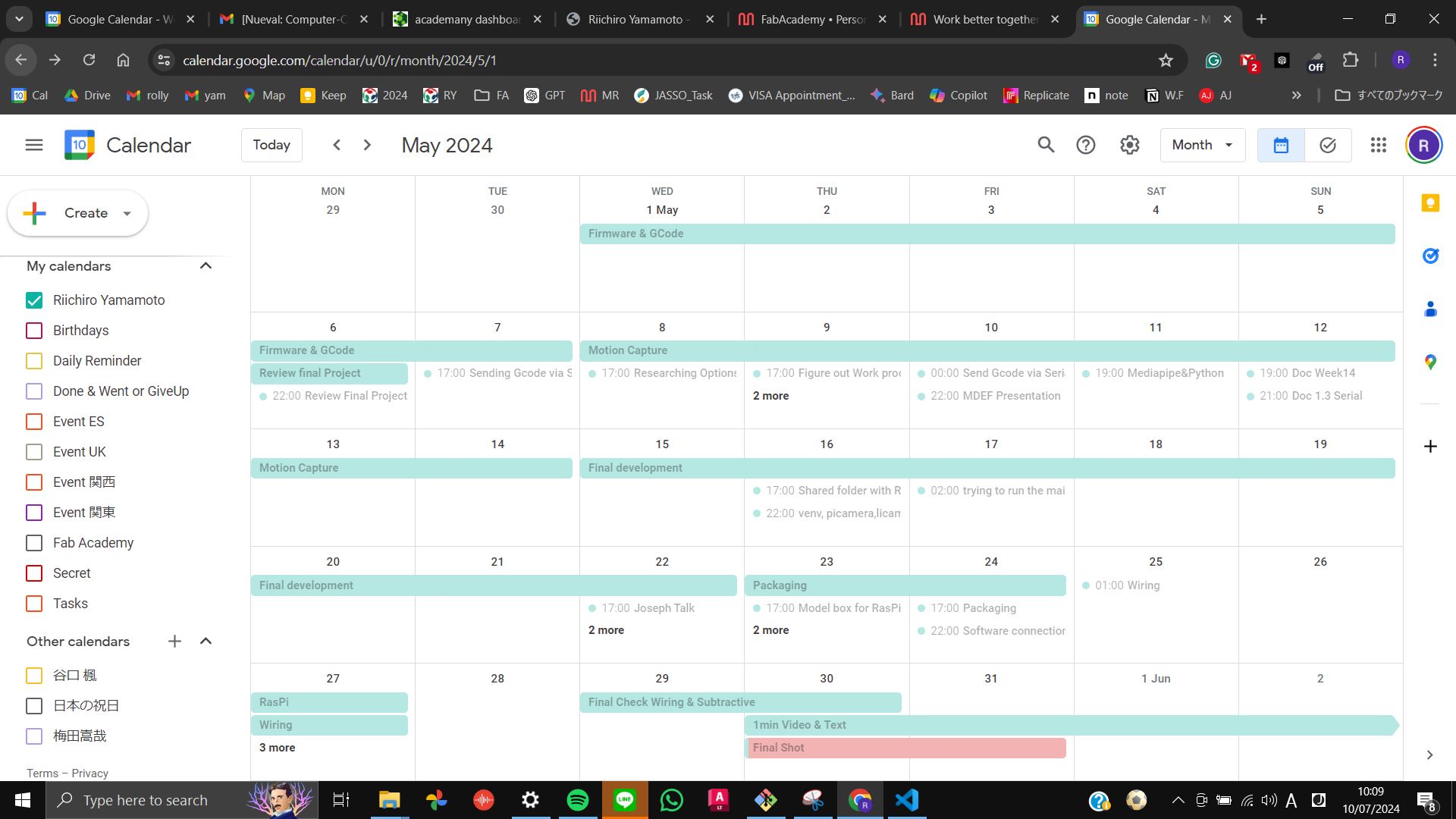
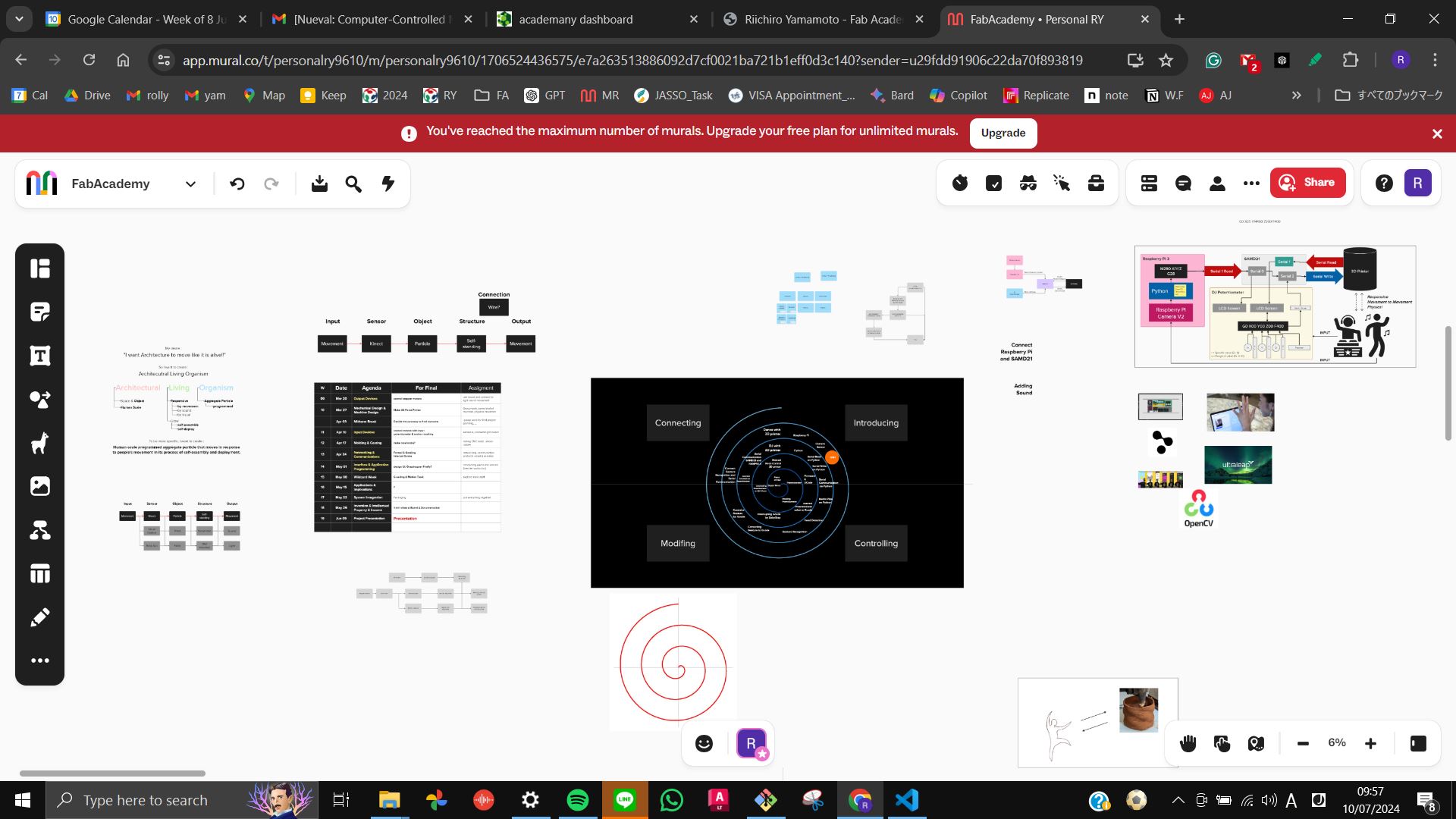
Keepingon track
To keep on track with my final project, I used Mural for overall schedule and goals for each week.
As the program got close to the final presentation, I started to create detail schedule on Google Calender for setting tasks for each day.