Week 5
3D Scanning and Printing
Fab Academy 2024
Riichiro Yamamoto
Dear My Friend
This week I was introduced to 3D Printing and 3D Scanning. It was something I experienced a little before, but I could understand them a lot deeper this time in the sense of how the machine operates, and what I can and can not do with 3D Printing and 3D Scanning.Hope you enjoy
Riichiro Yamamoto
Group Assignment
this week's group assignment was to test the design rules for your 3D printer
Here is the link to the group assignment page
3D Scanning with Kinect
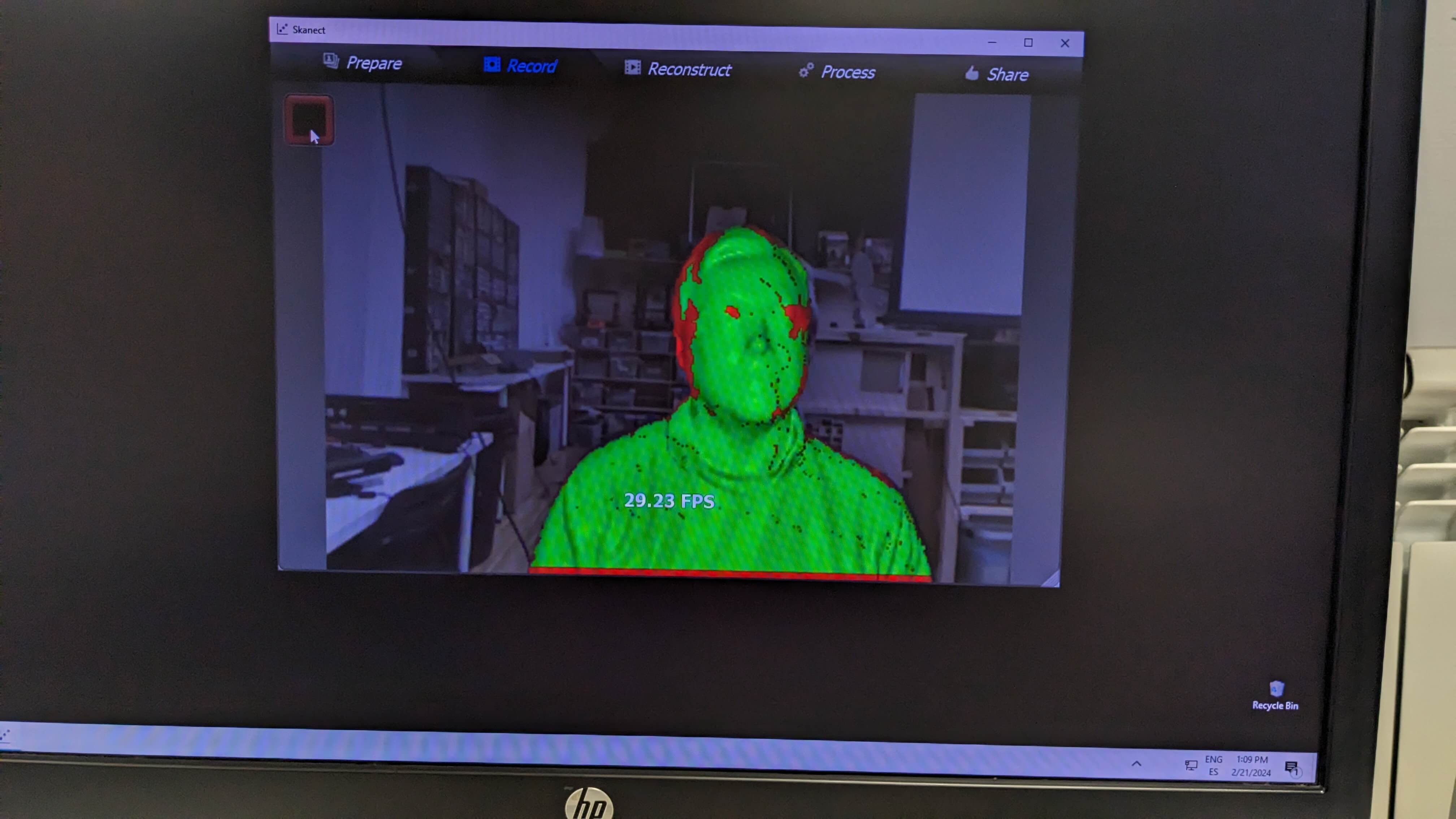
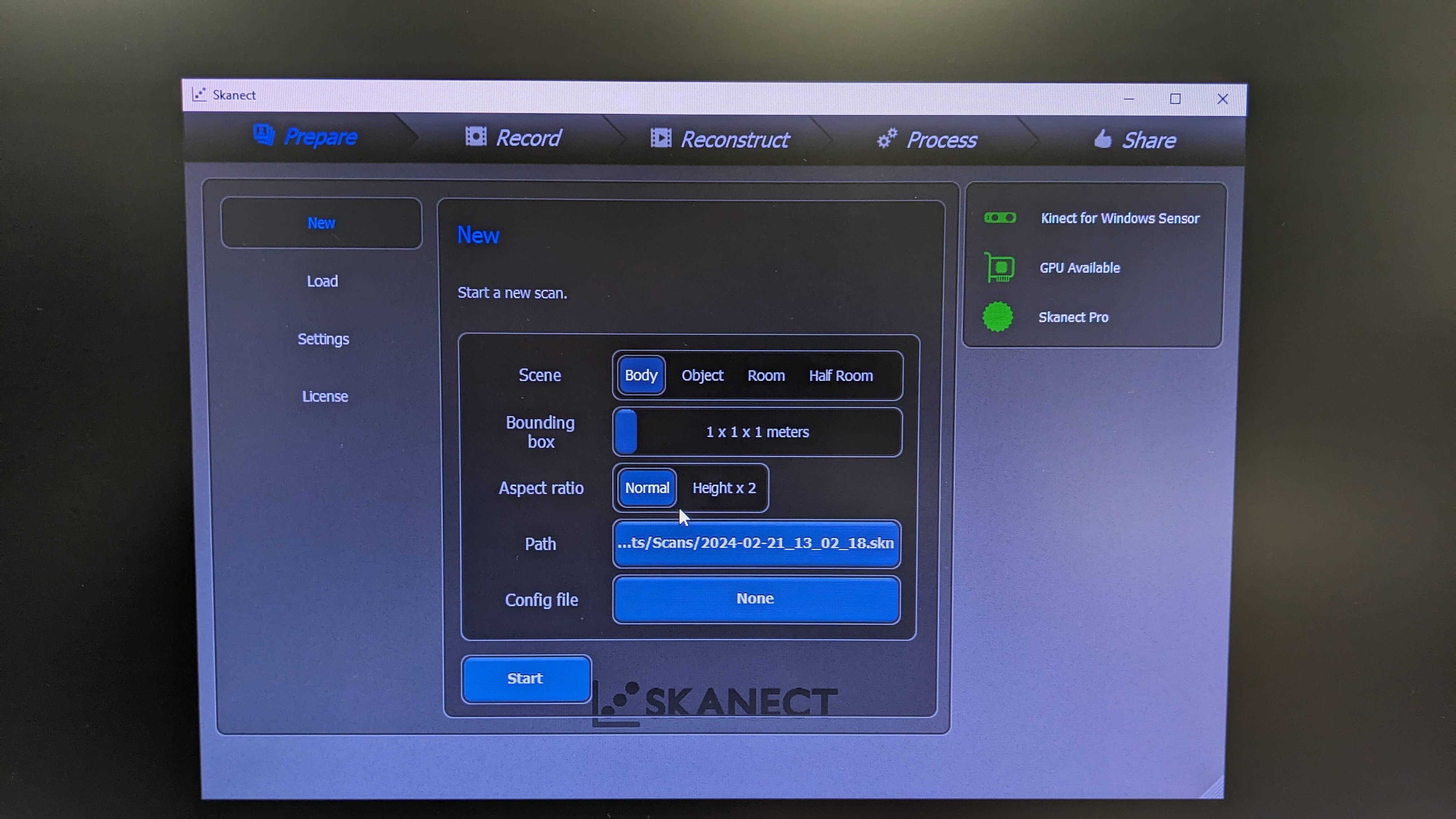
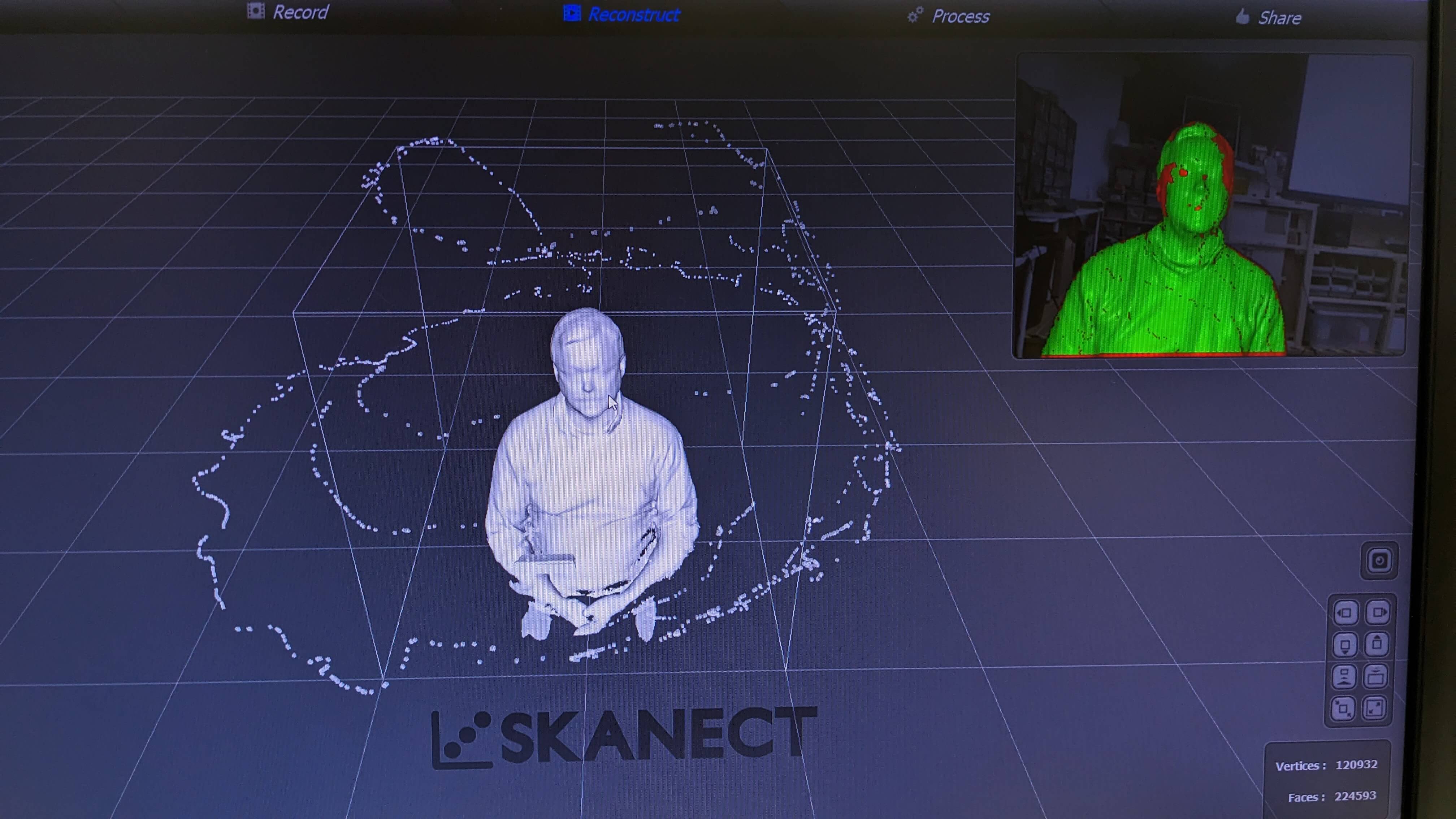
I first 3D-scanned my classmate using Kinect. Kinect is a censoring device made for Xbox but it can be used in 3D scanning. I used software called Skanect to use Kinect for 3D Scanning.
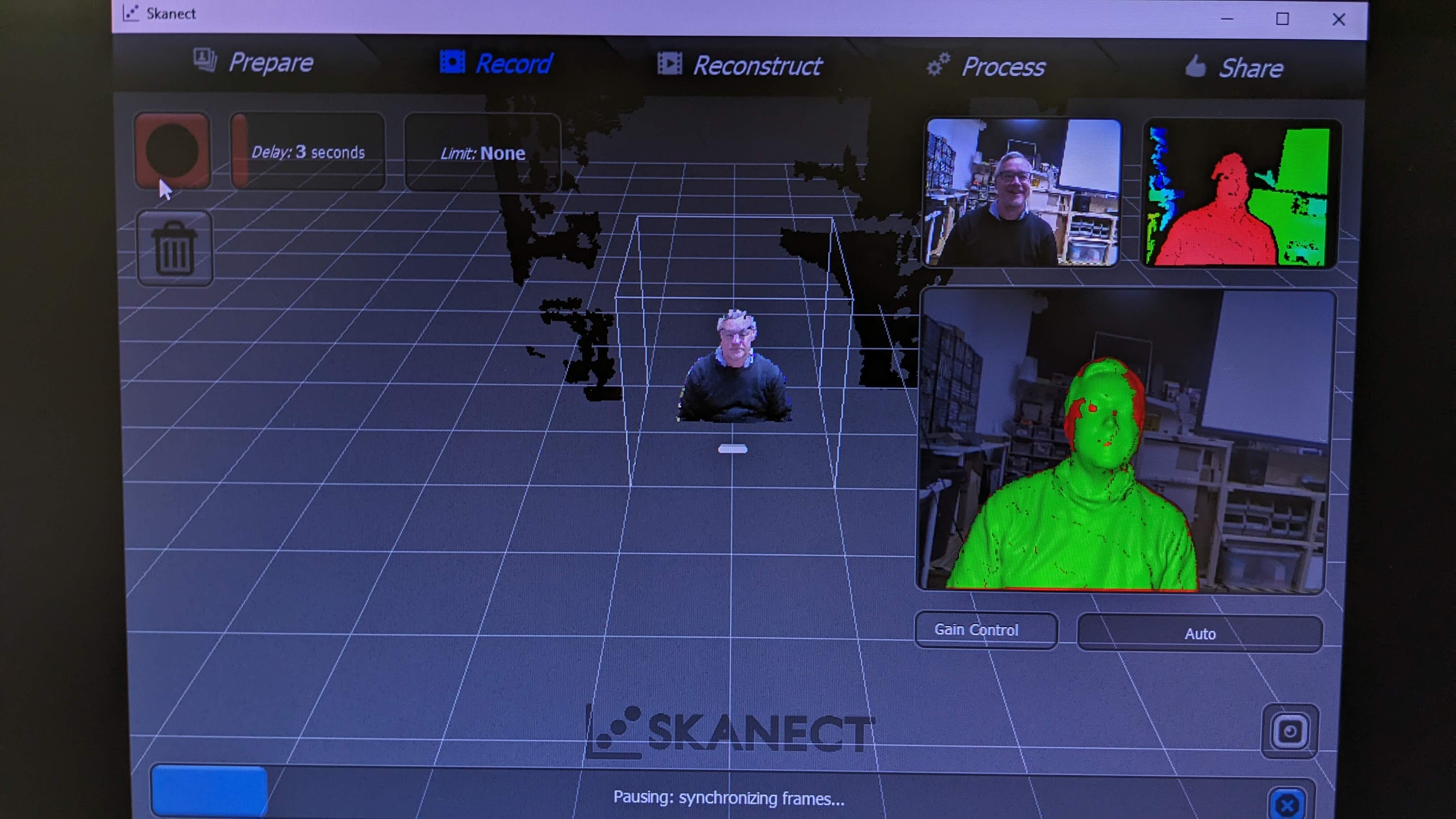
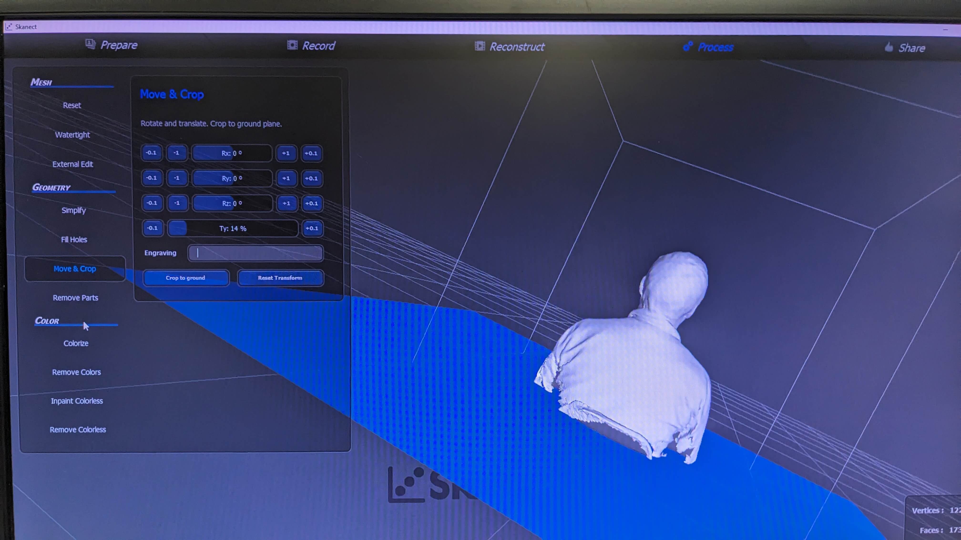
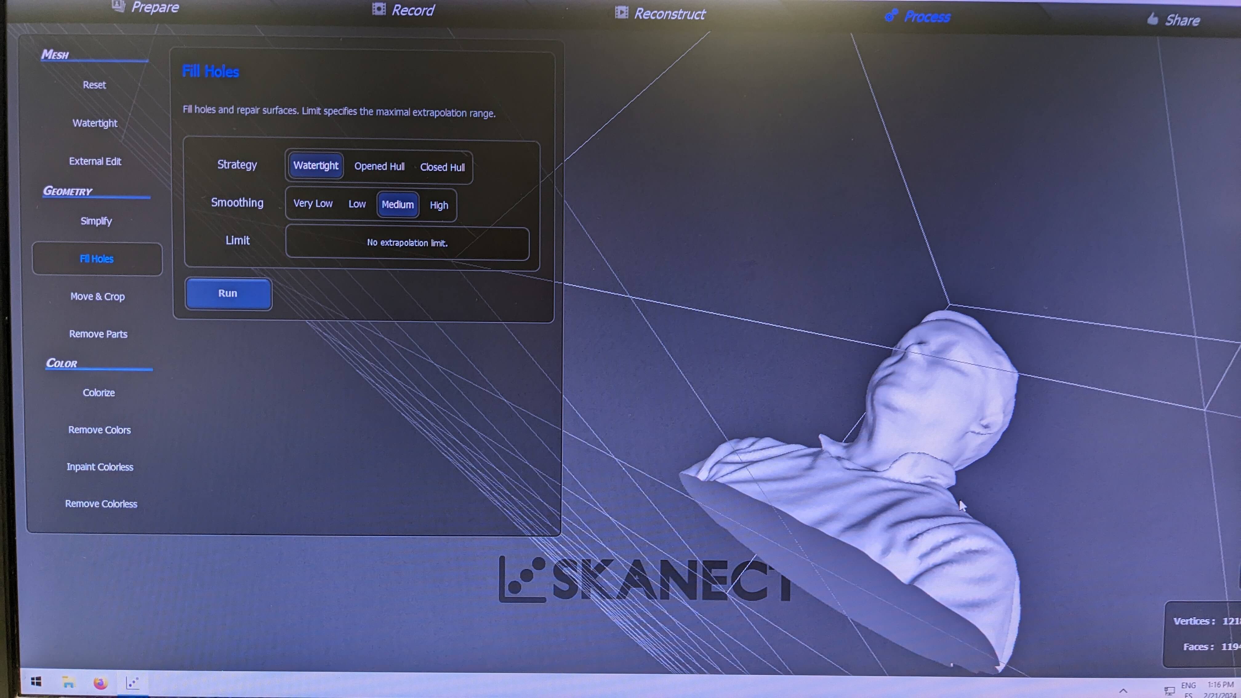
After launching the software and connecting with Kinect, I simply adjust the settings suitable for what I want to scan. This time I am only scanning the upper body of my classmate so I set the Sense to Body, Bounding box to 1x1x1 meters, and Aspect ratio to Normal. Then I press a button to start scanning. It was important to hold Kinect (the scanning device) steady and move slowly around the object when I was scanning. Also, It is important to scan from all angles to try the scanned mesh data as cleanly as possible without any holes. After scanning, there is post-processing. In the post-processing, I was able to check my scanned data. Then I got rid of unnecessary parts of the data, cropped the geometry, and filled holes. Finally, I had the clean 3D scanned geometry of my classmate, and I exported it in an OBJ file.
Files
ScanedClassmate.obj
Photogrammetry
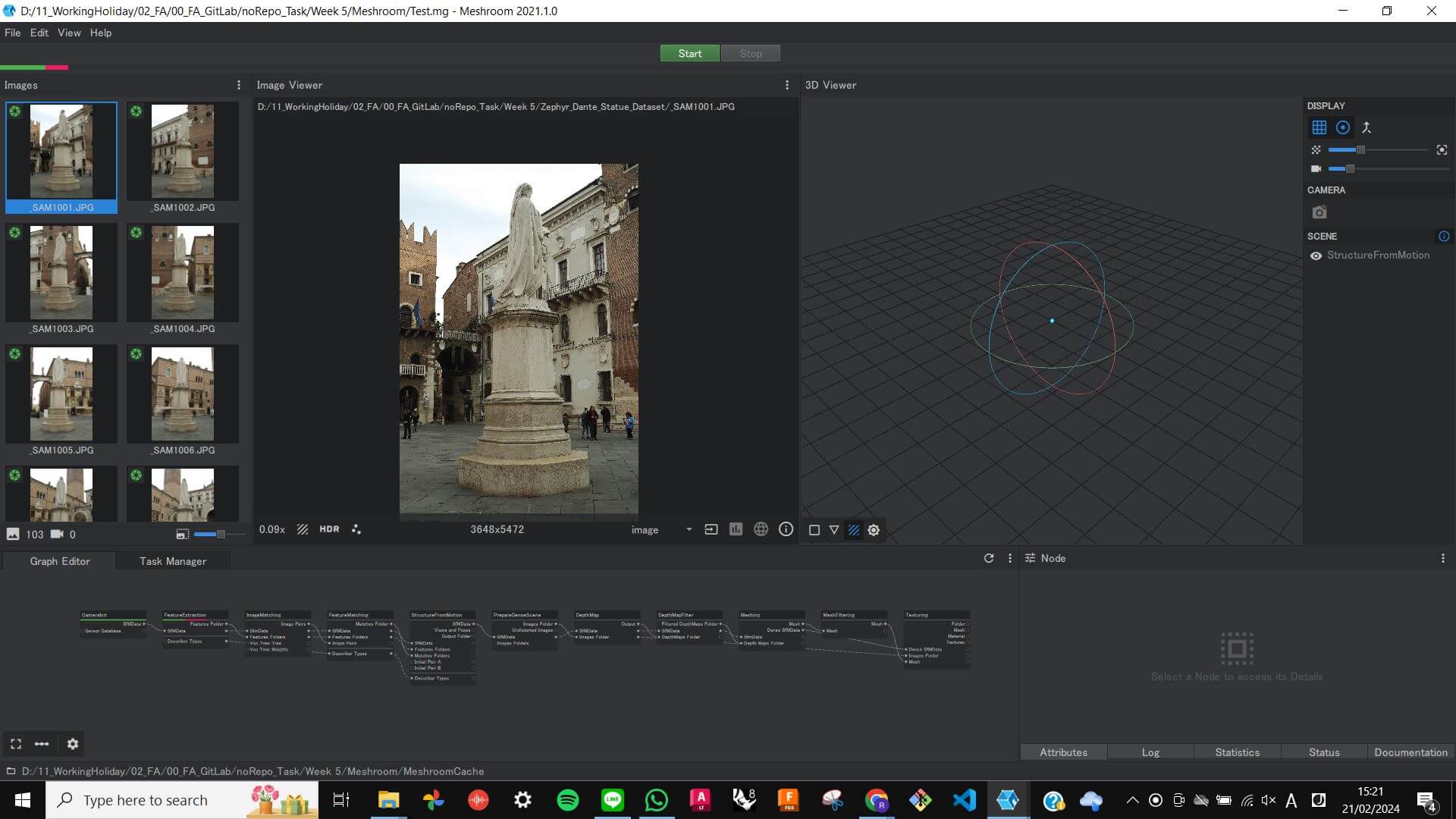
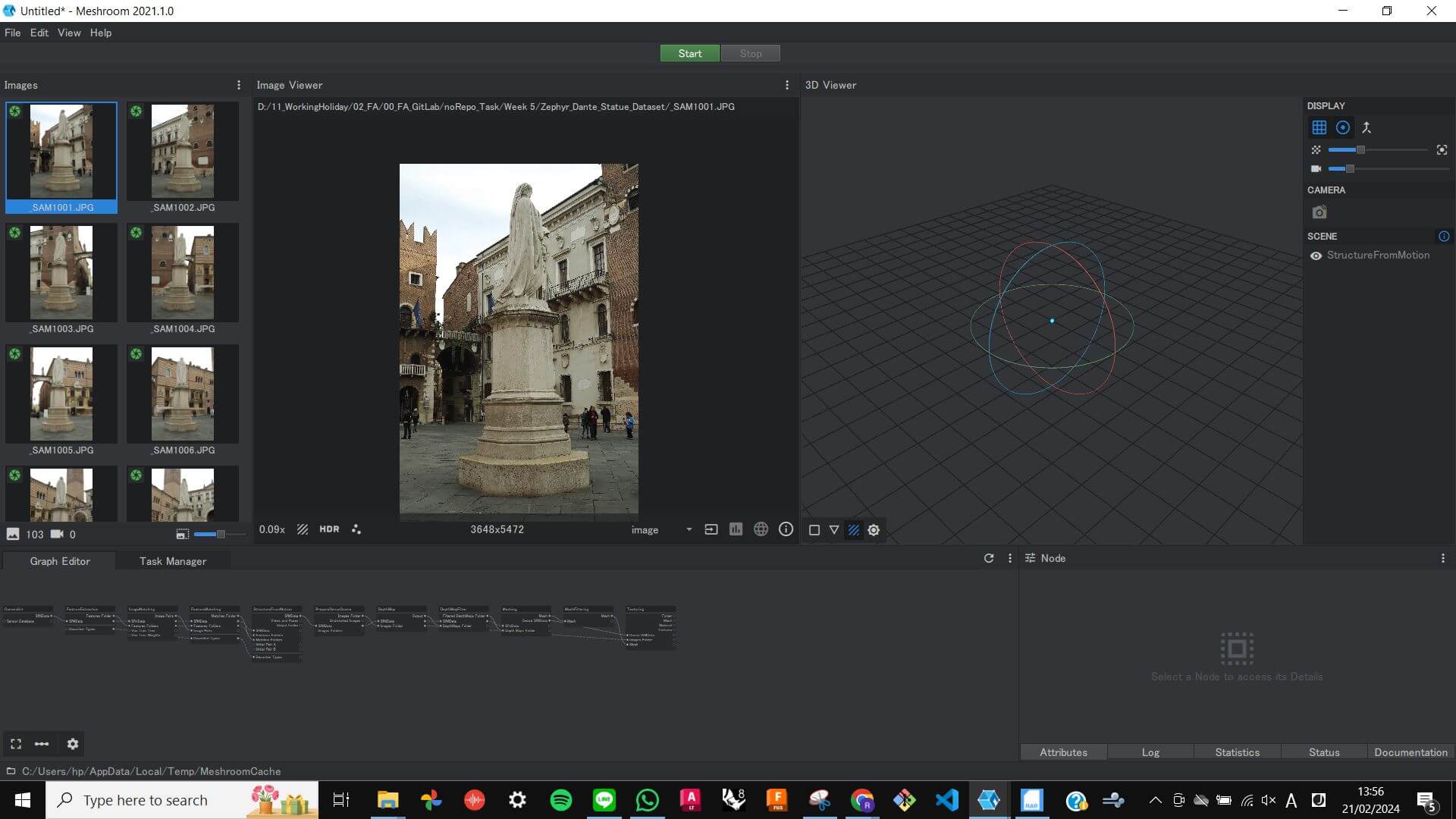
I wanted to try photogrammetry with Meshroom. After I installed Meshroom I needed to get a data set for Photogrammetry. (basically a bunch of images of an object from all angles) To get the data set I simply went on Google search and found a data set of Dante’s Statue.
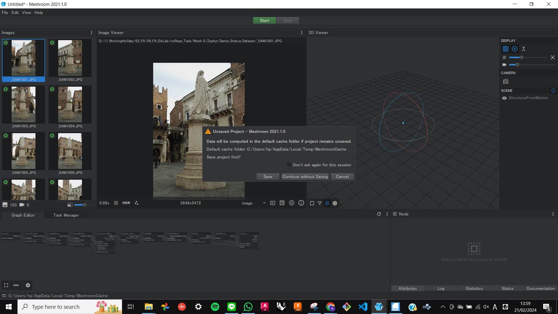
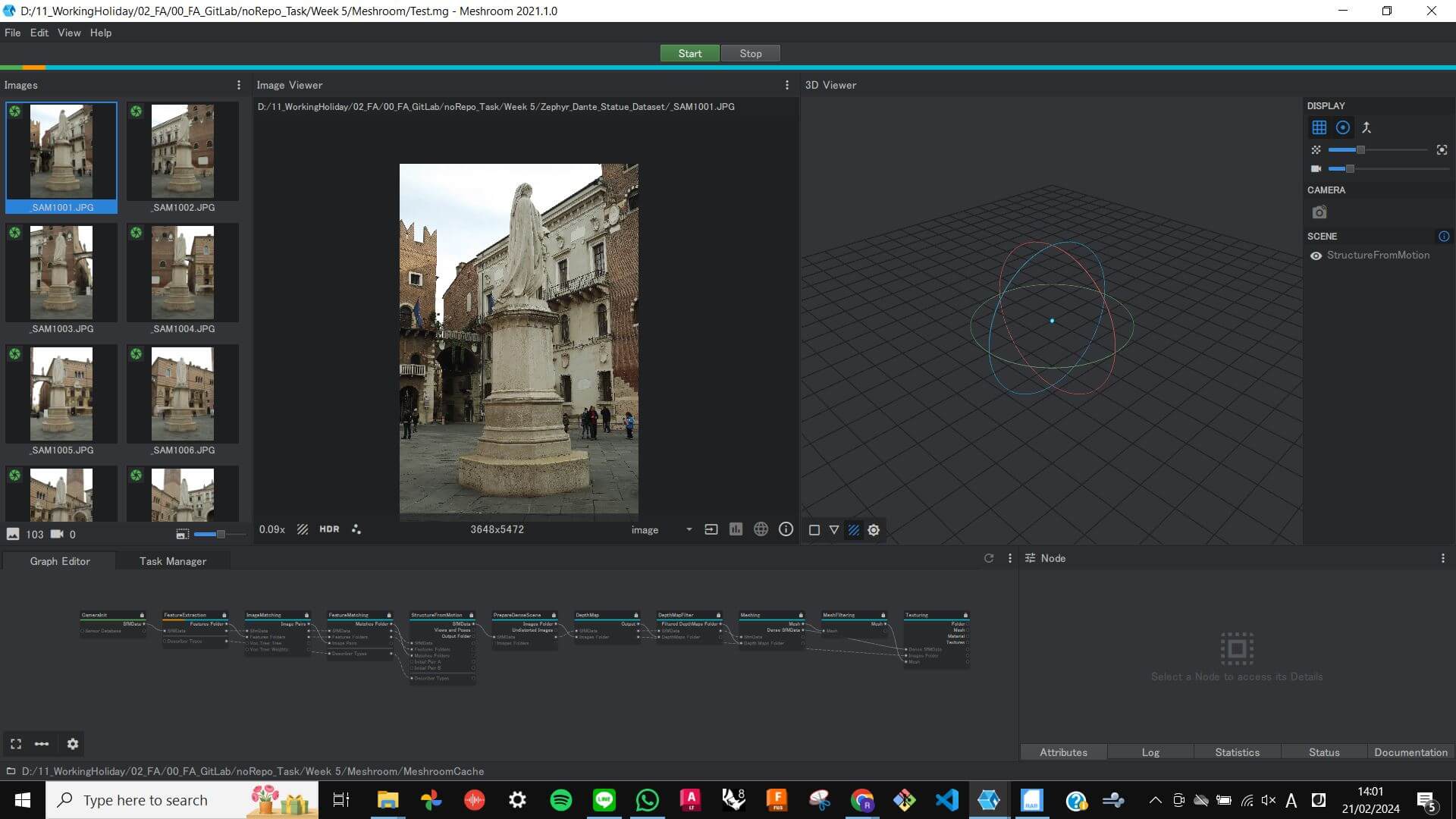
After downloading all the images, I imported them into Meshroom and simply started the automated photogrammetry process. However It was processing very slowly, and it only processed few percentage of the entire process after waiting for 30 minutes. Also, It was making my PC very slow so at this point I decided to cancel the process. I think this process requires a stronger and faster PC. I would like to try it with different PCs or explore different ways of making photogrammetry.
3D Printing: Nervous System
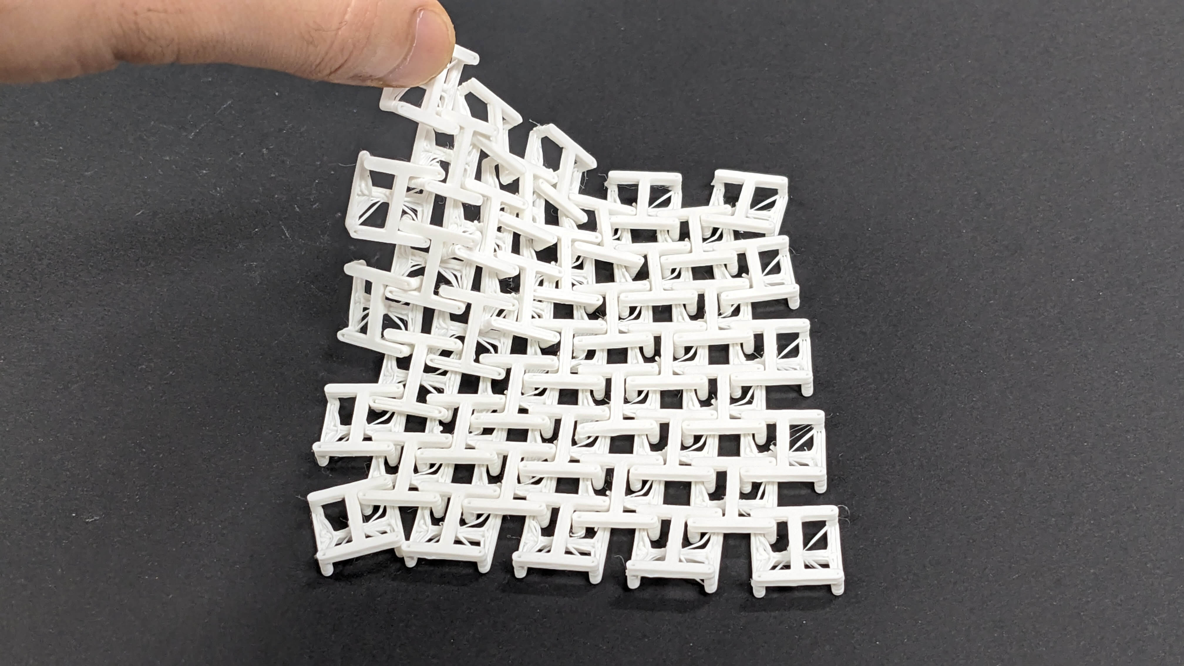
When I asked for advice from my tutor, he showed me a previous example of 3d 3D-printed Kinematic dress done by Nervous System Design. Since this structure allows the object to move, I wanted to quickly try 3D printing a small piece of it.
Modelling
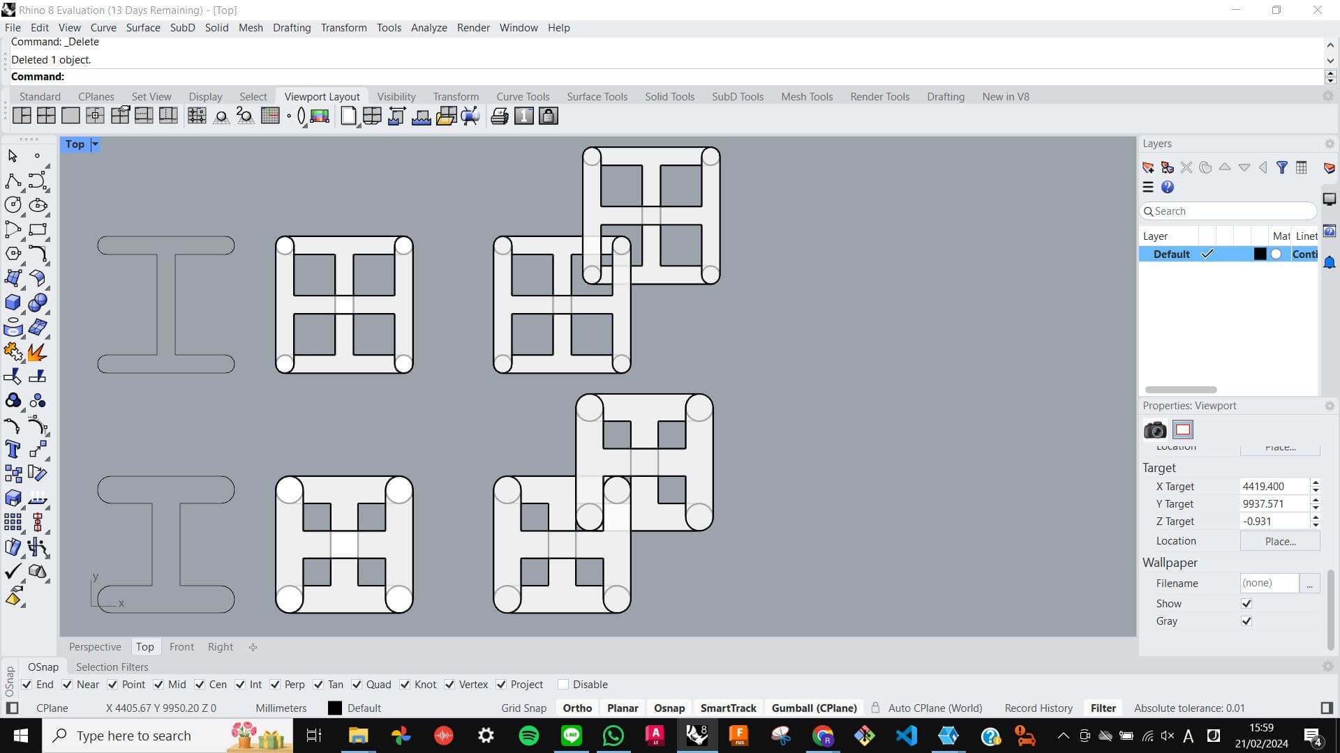
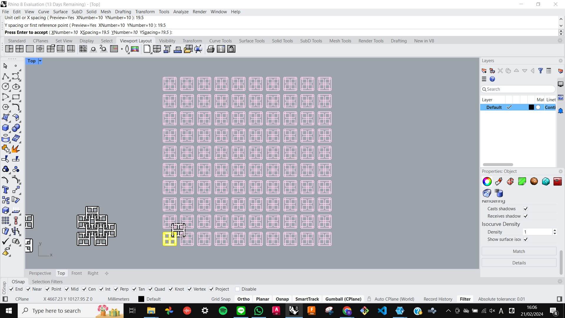
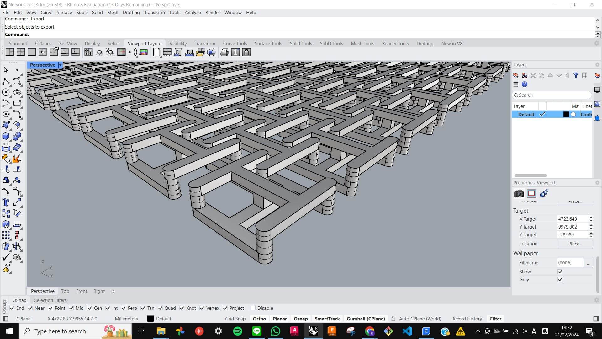
To understand, I carefully measured the example and started to make a replicated model in Rhino. Firstly, I drew a basic shape in 2D and then extruded it. Secondly, I made a copy of the model with 90 rotations and connected the gap between with a small extrusion. After that, I simply copied the entire piece and located it in a place to make a chain connection with the original piece. However, I realized that the dimension of the piece was to thick to to have some space for another piece to move so I remodelled a piece with a thinner dimension. Finally, I arrayed 10 of the first piece and 9 of the second piece with certain spacing to get the model ready for 3D printing.
FilesNervous_test_PRINT_small.stl
Slicing
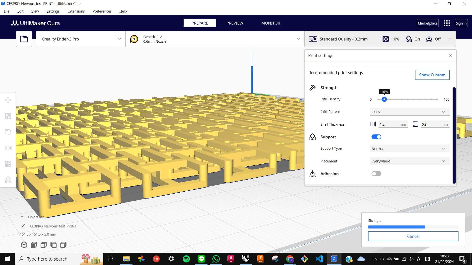
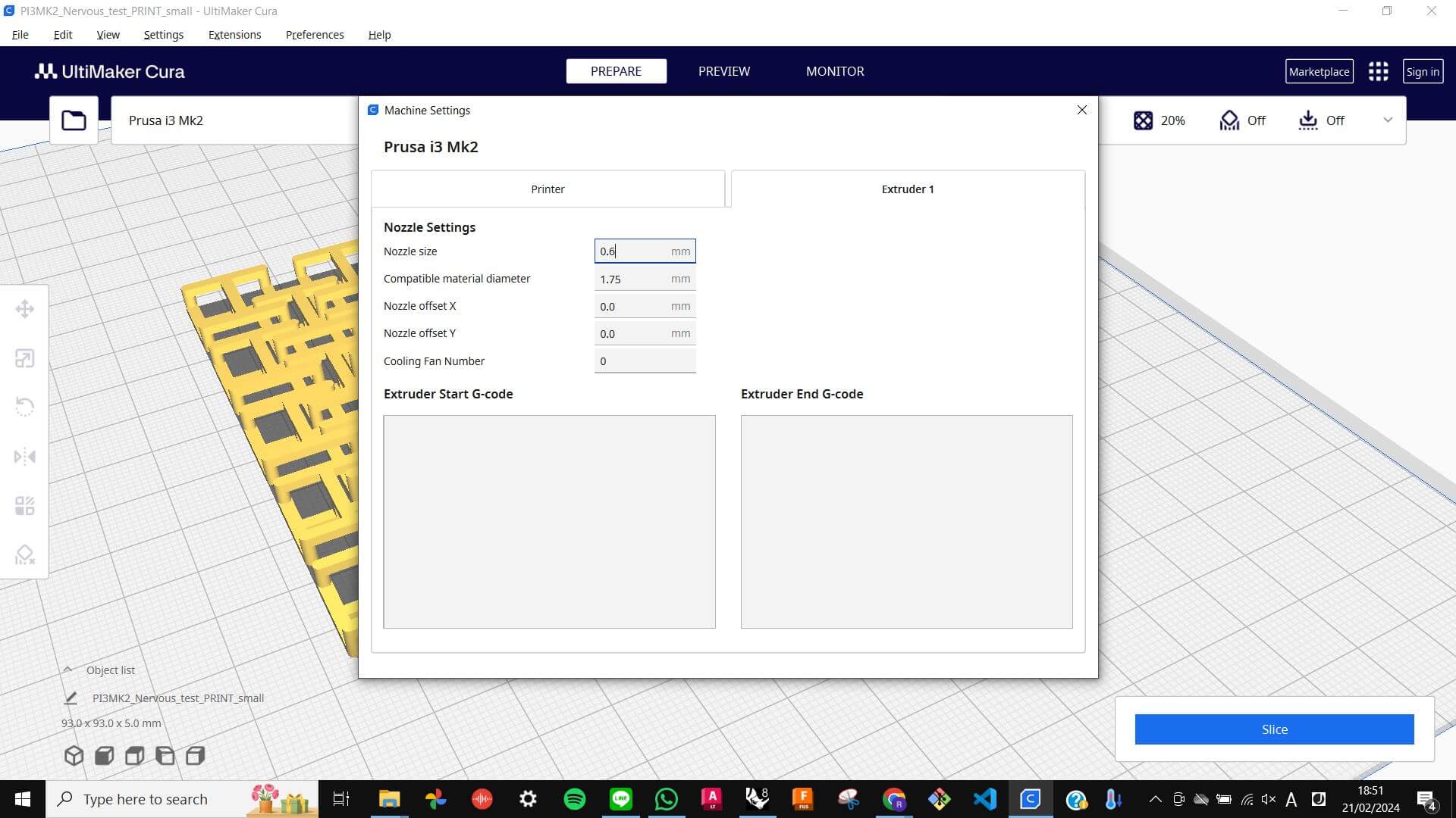
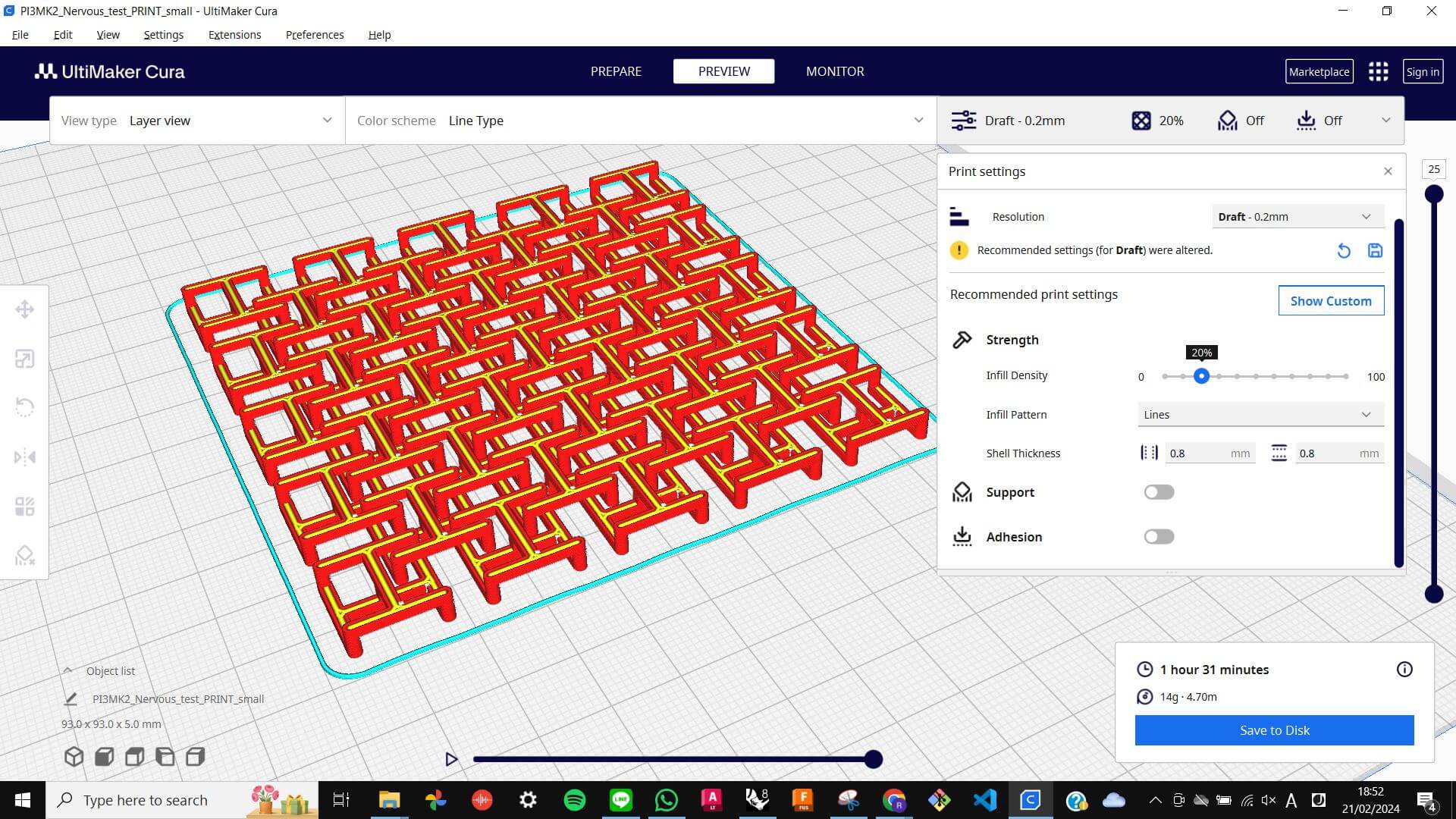
Before sending the file to a 3D printing machine, I always need to go through the Slicing process. For that I used Cura. In Cura, I can define the type of 3D printing machine, change infill, add supports, and define resolution. This time I used Prusa i3 MK2 for the machine, 20% Lines for infill, no support, and Draft 0.2mm for the resolution. To get a good understanding and be able to choose the right setting for how I want the outcome to be, I think I need to try a couple of times with different objects and settings. I think this slicing process is crucial because if I have the wrong setting it could lead to unnecessary overuse of material and printing time. Anyway, this time I checked with my tutor about the setting and it was ready for printing.
FilesPI3MK2_Nervous_test_PRINT_small.gcode
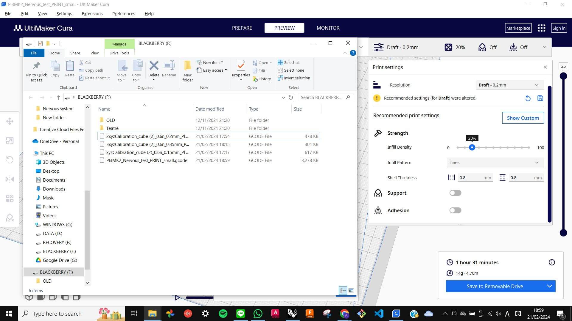
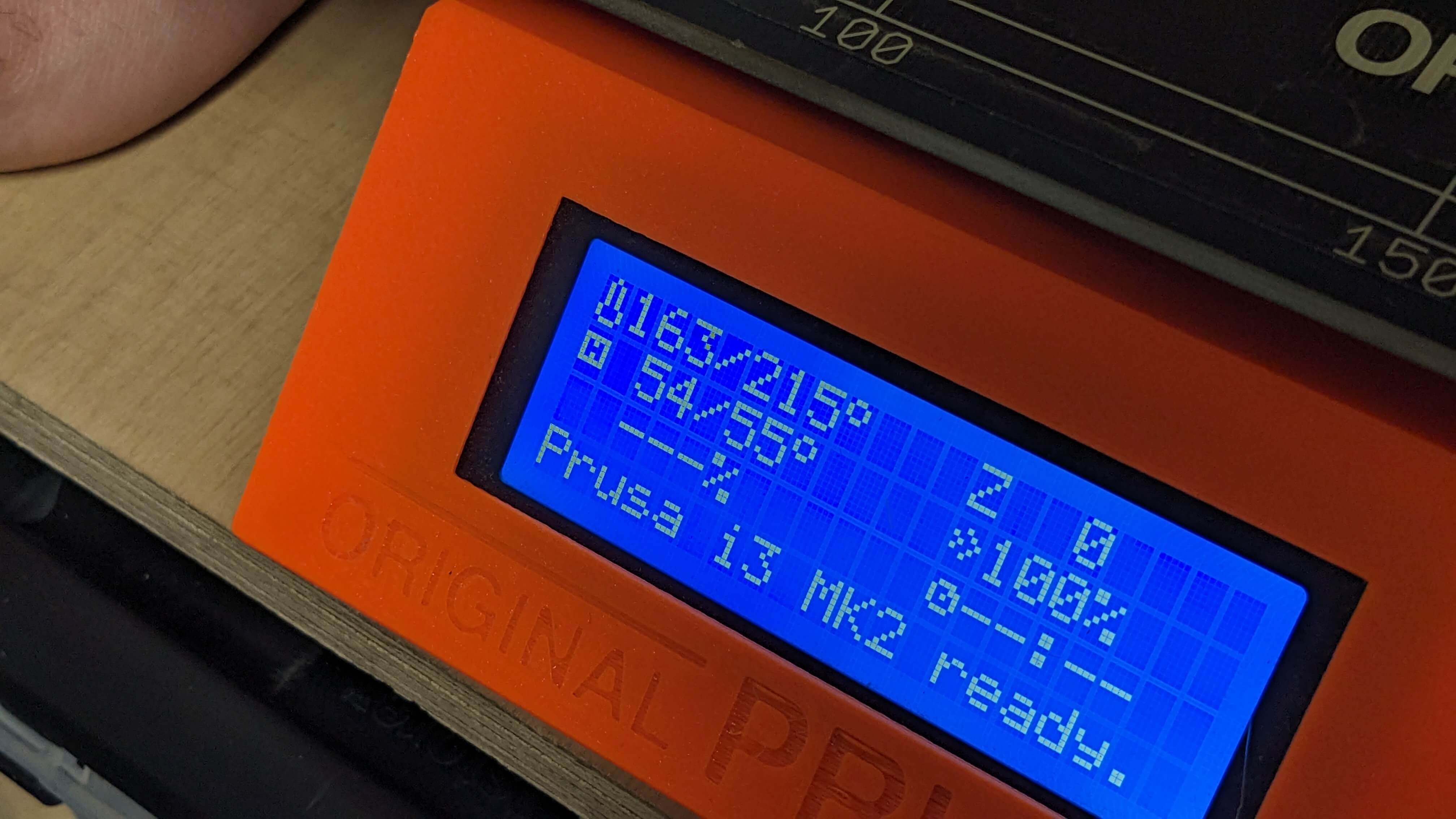
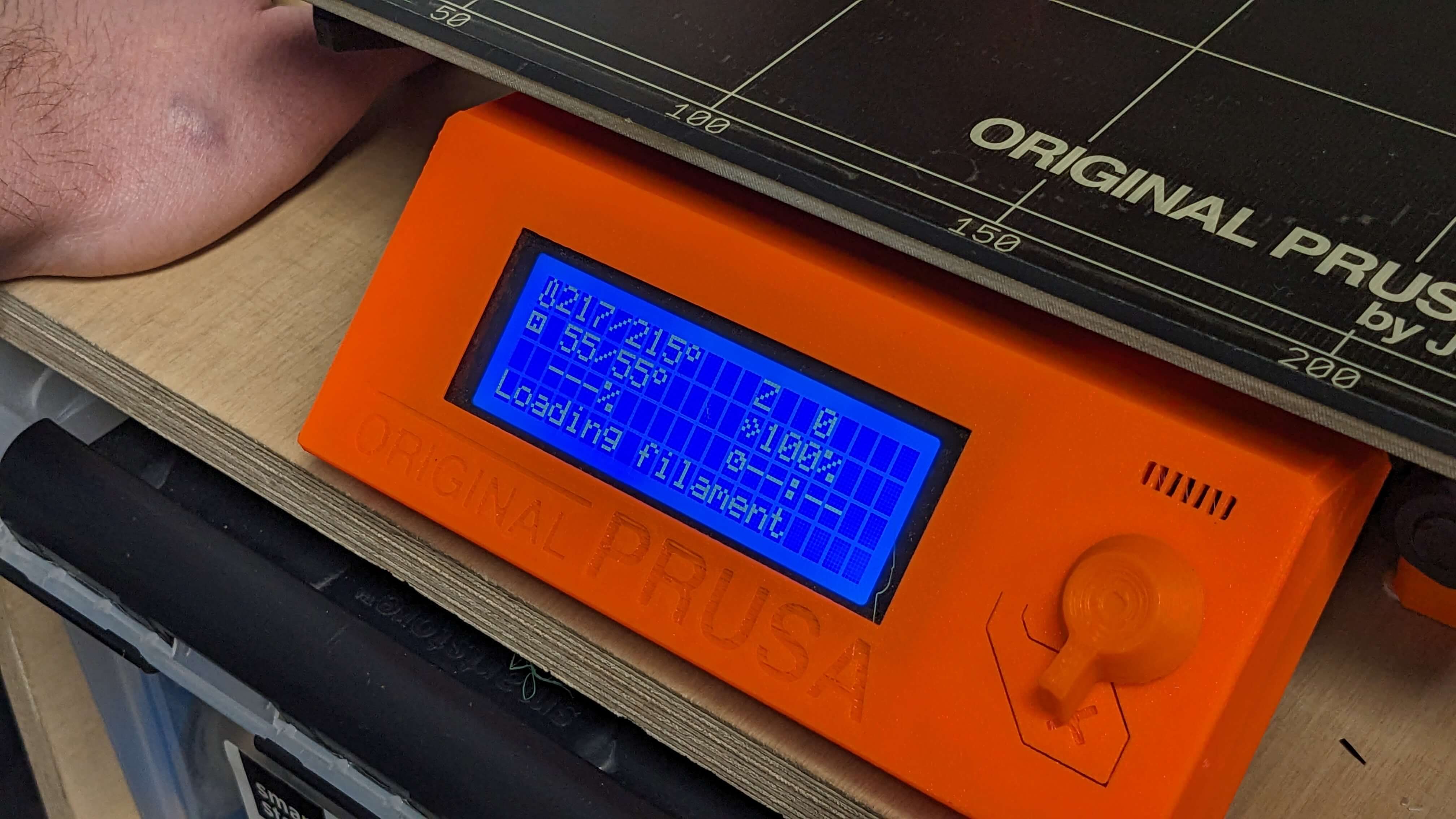
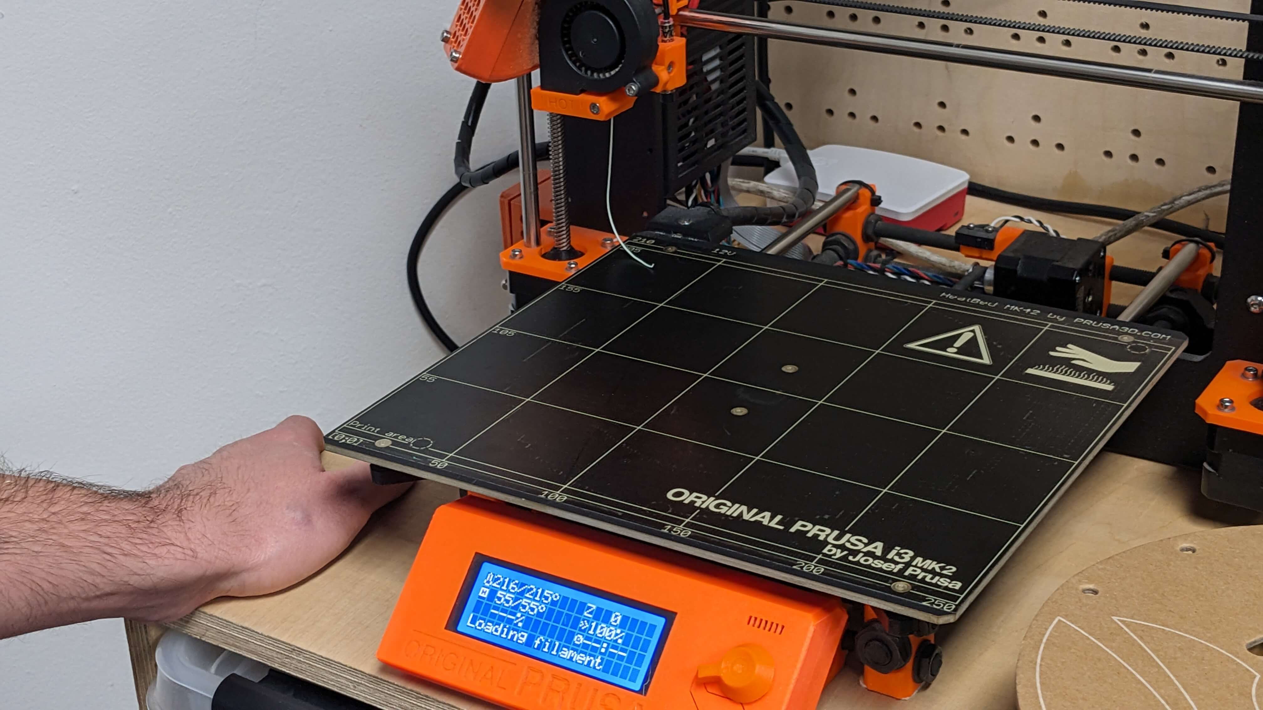
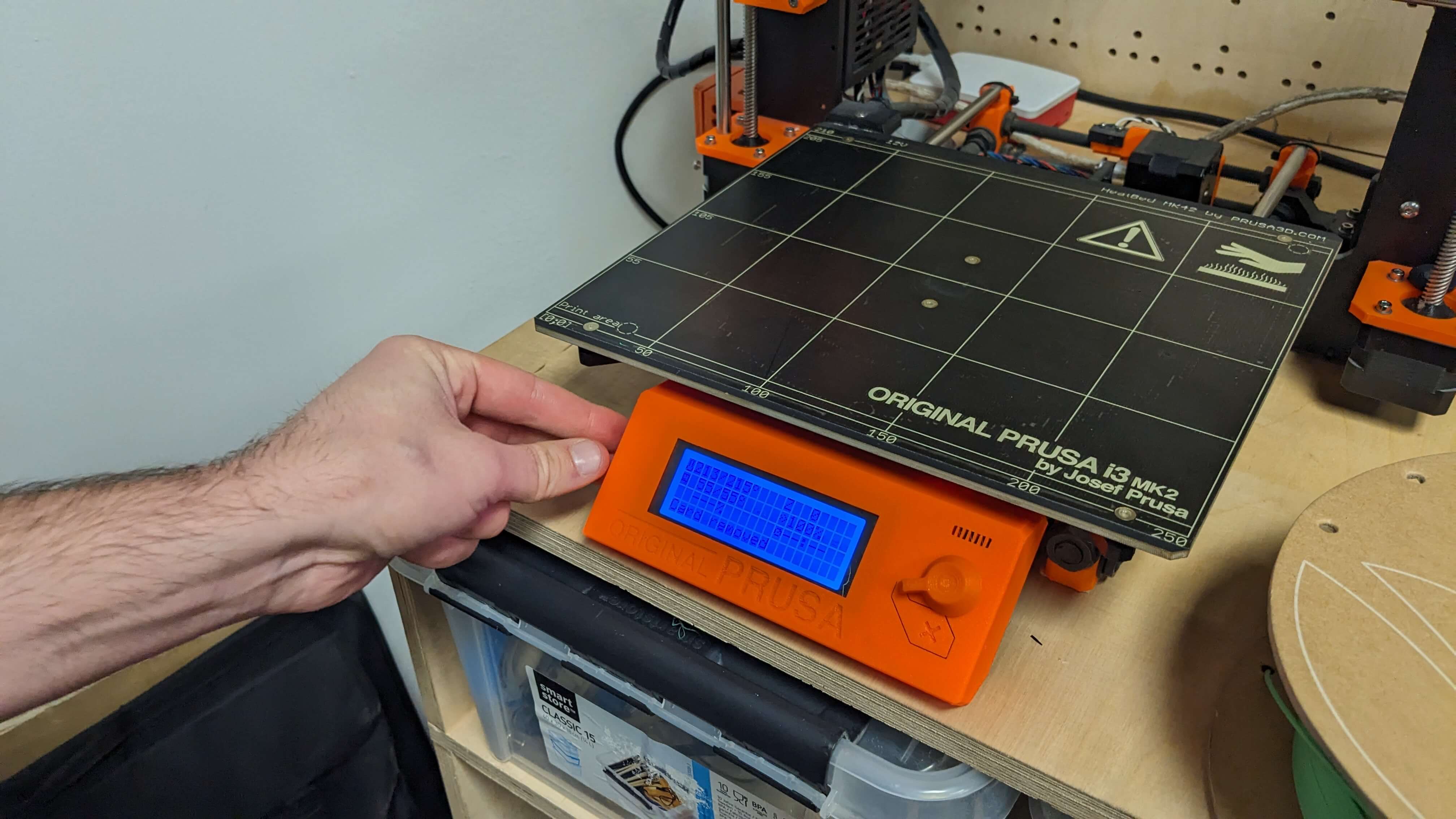
Printing with Prusa i3 MK2
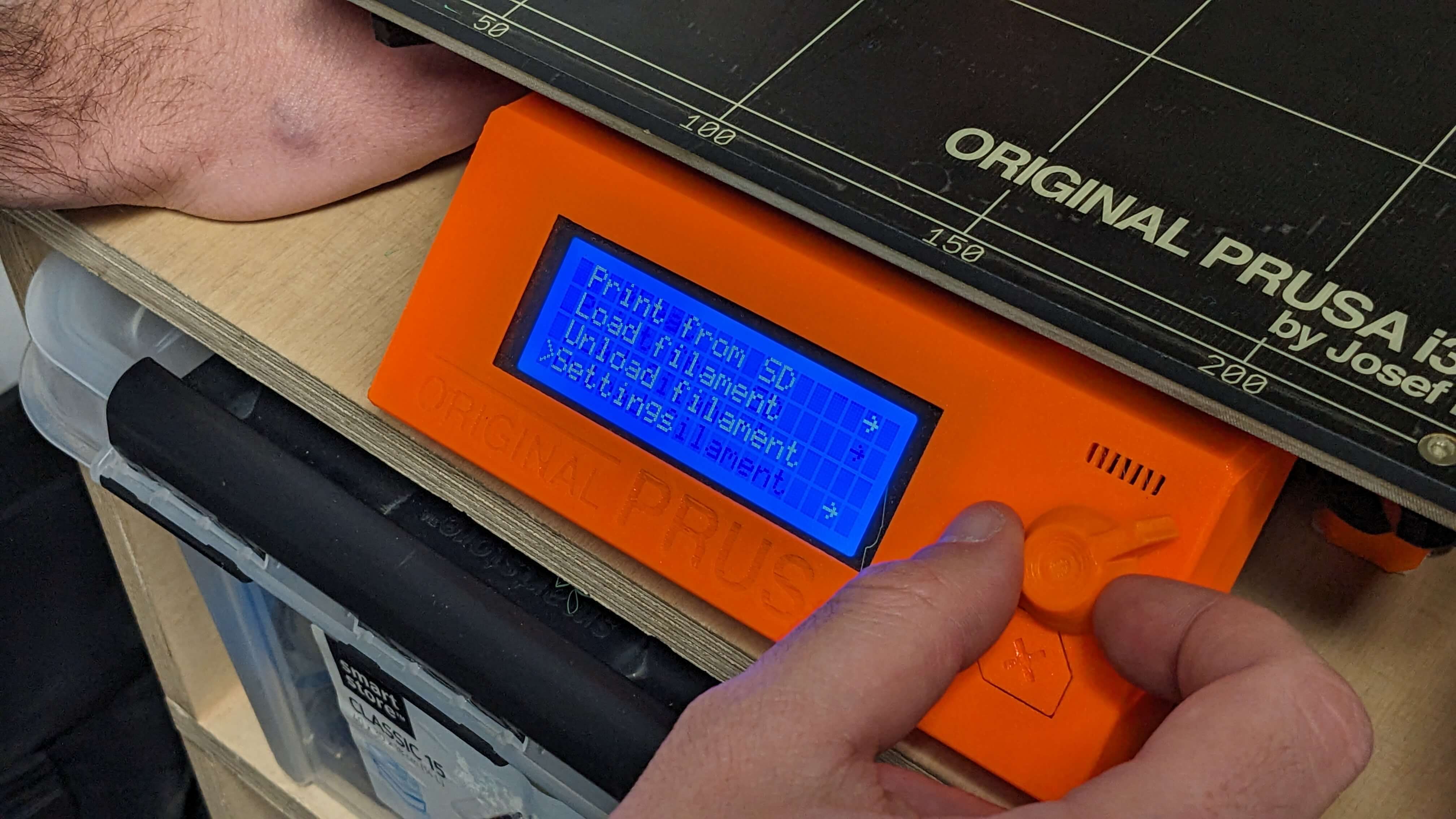
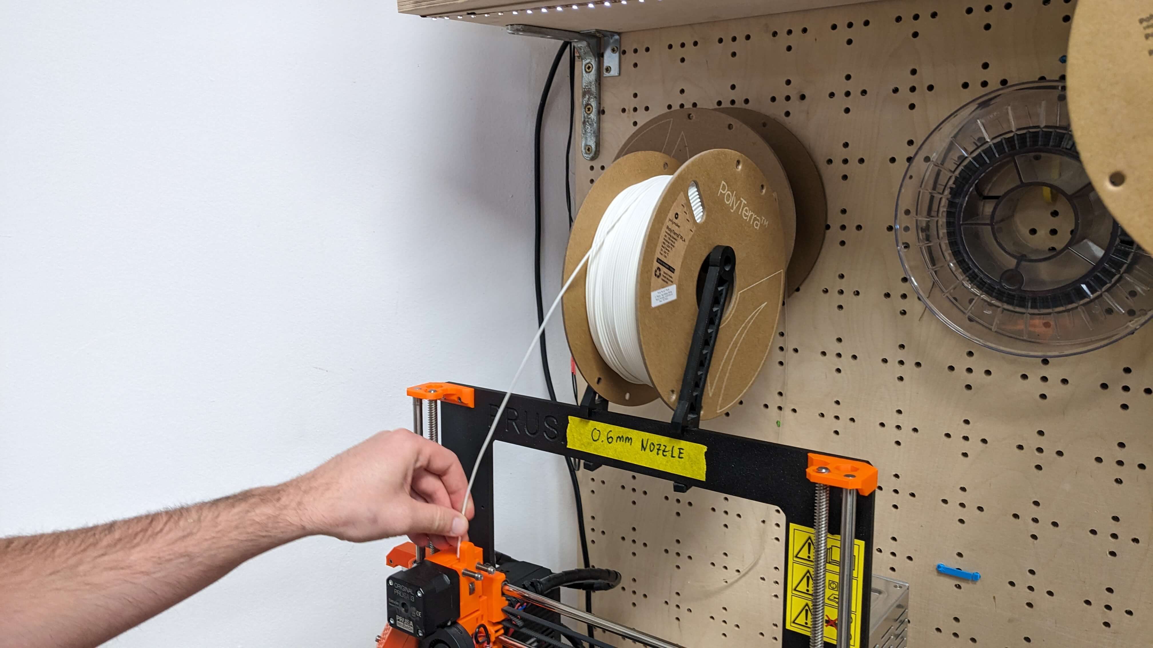
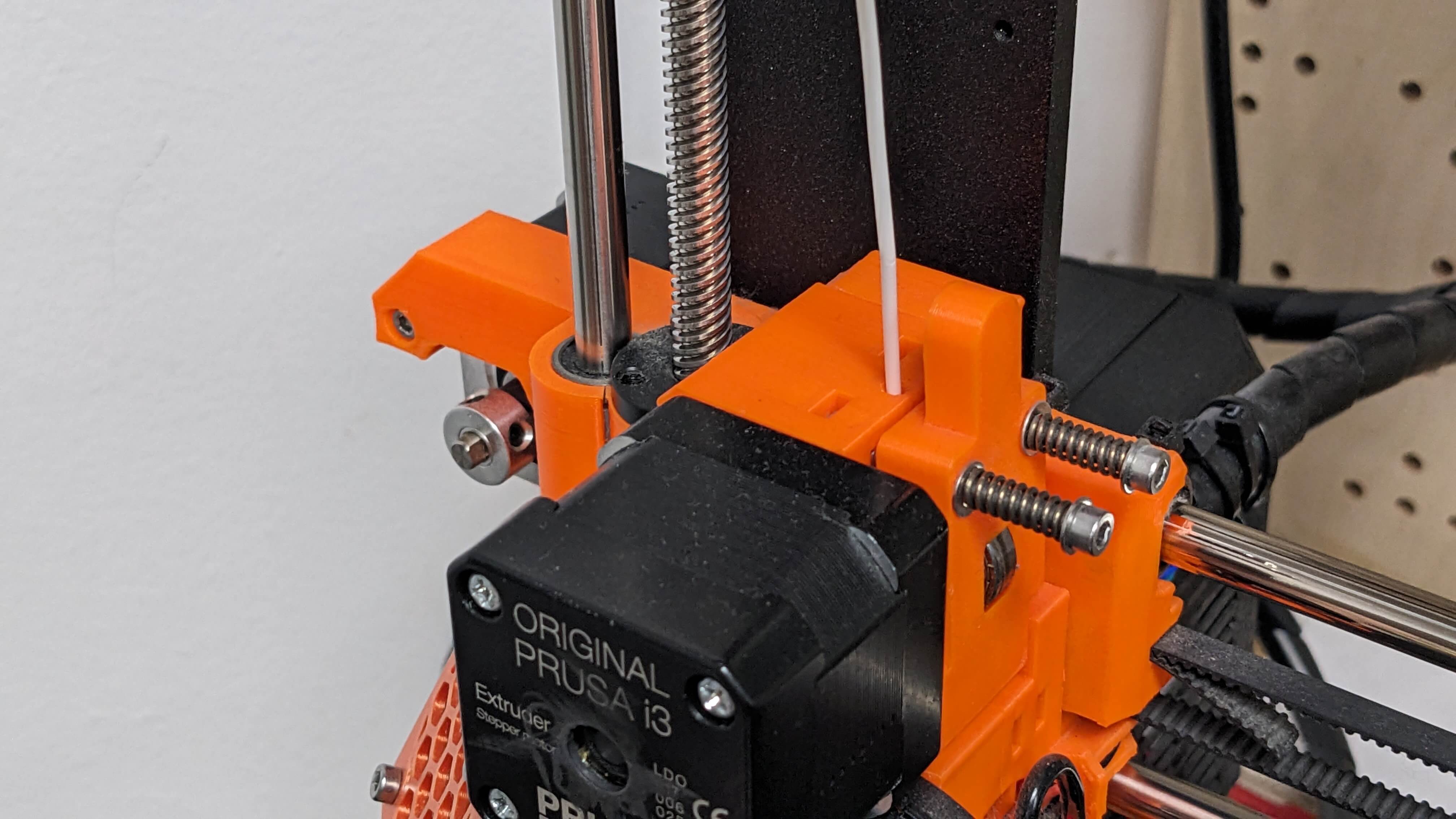
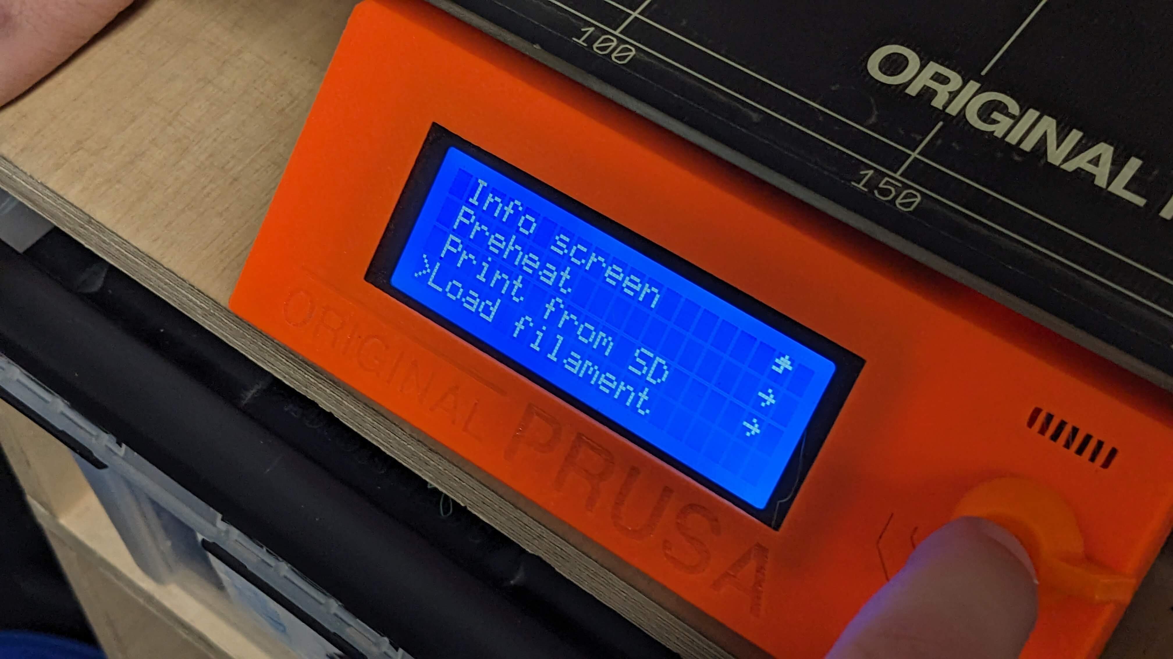
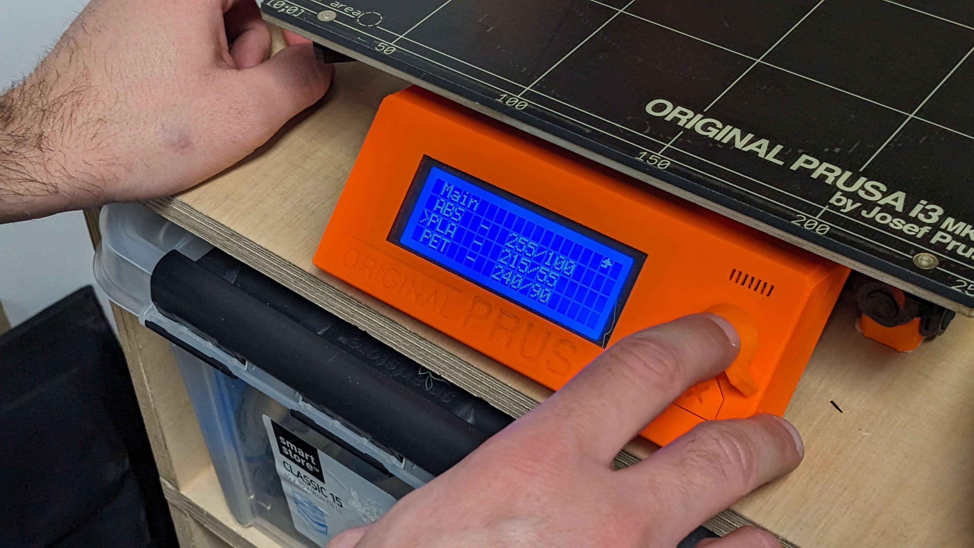
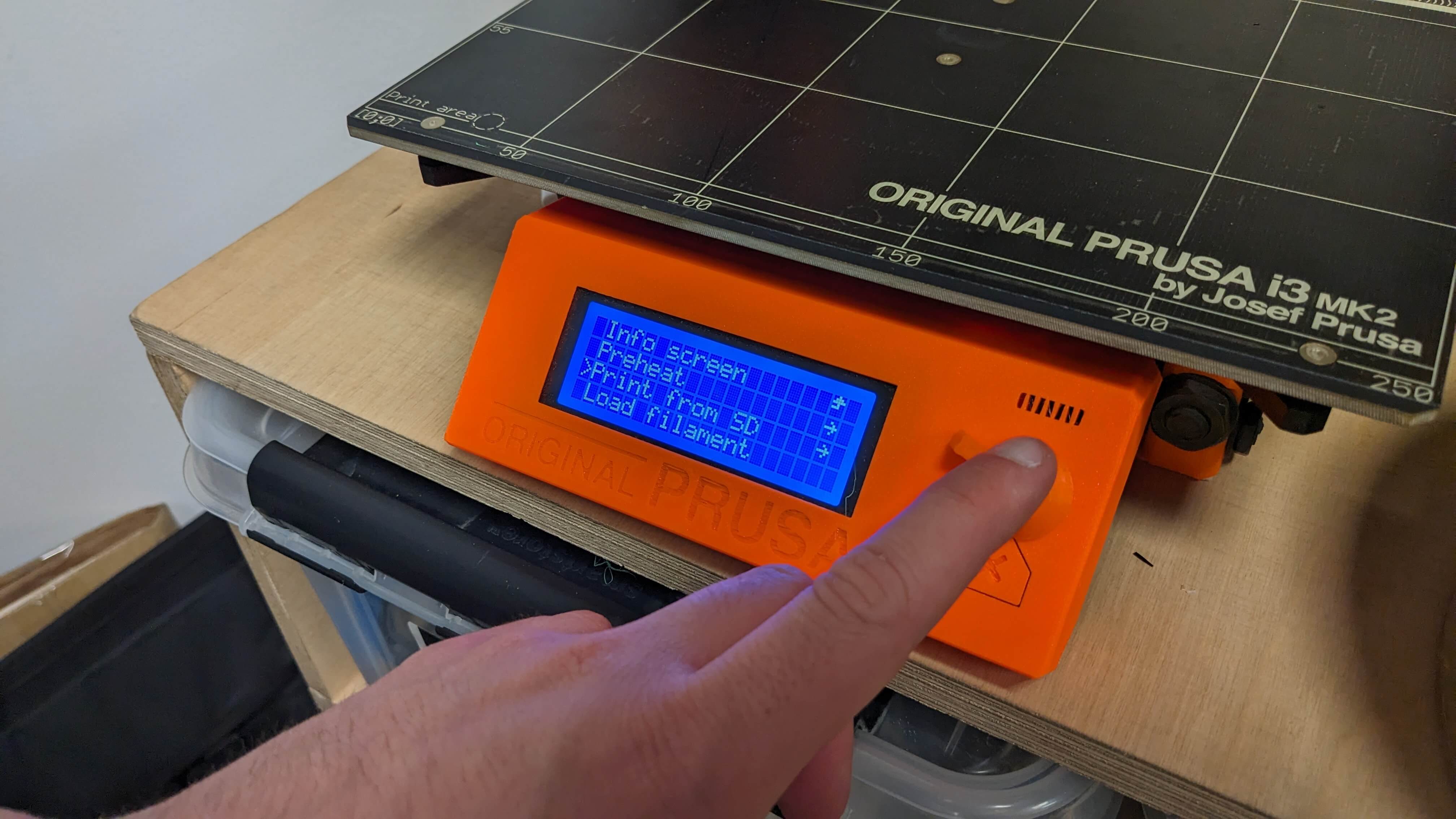
Before starting 3D printing, I needed to get the machine ready. First I changed the filament by unloading the previous filament and loading the filament I wanted to use. Then I wait for the machine to extract all the leftover filaments from previous filaments until I see my filament. Then I pre-heat the head and bed. After that, I insert an SD card that has the file that I want to print. Then go to Print from SD, choose that file and start printing.
Problem
The first trial was a failure because some parts of the model were not sticking to the bed and came off in the printing process. I think it has to do with the temperature of the bed was not enough in some spots. Also, my friend told me that printing often goes wrong when it is the first time printing after changing the filament. So I decided to stop printing and printing again.
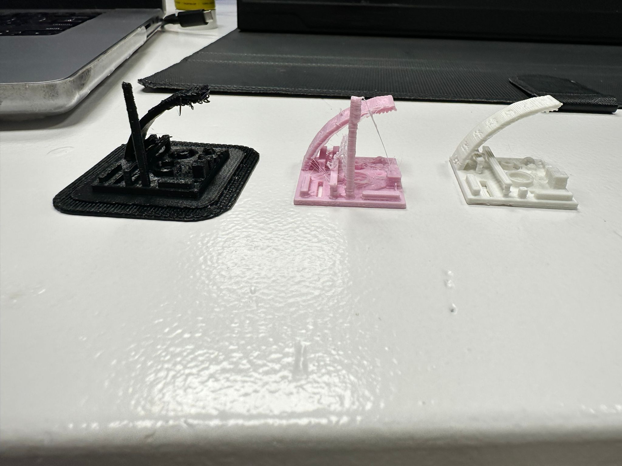
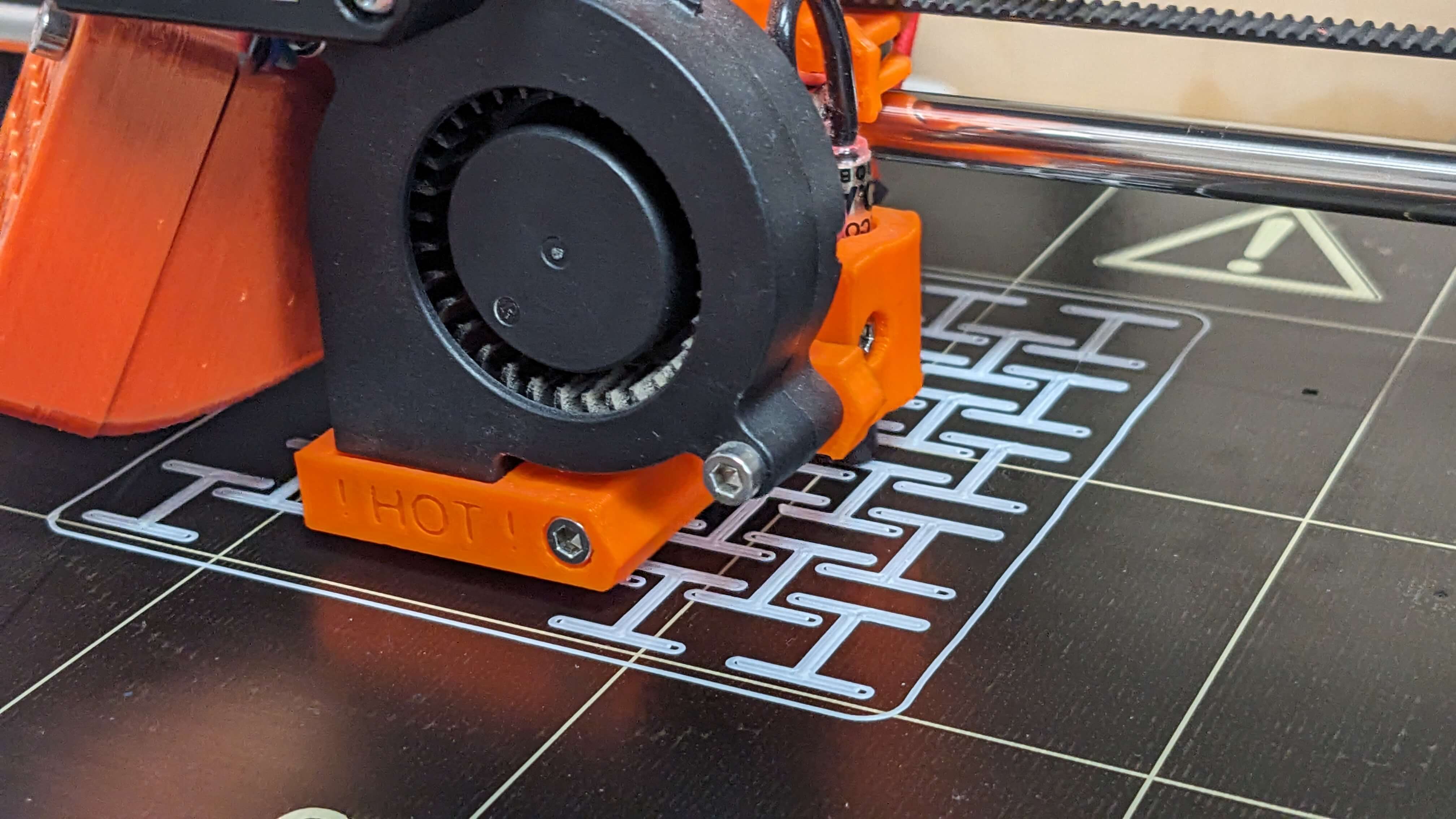
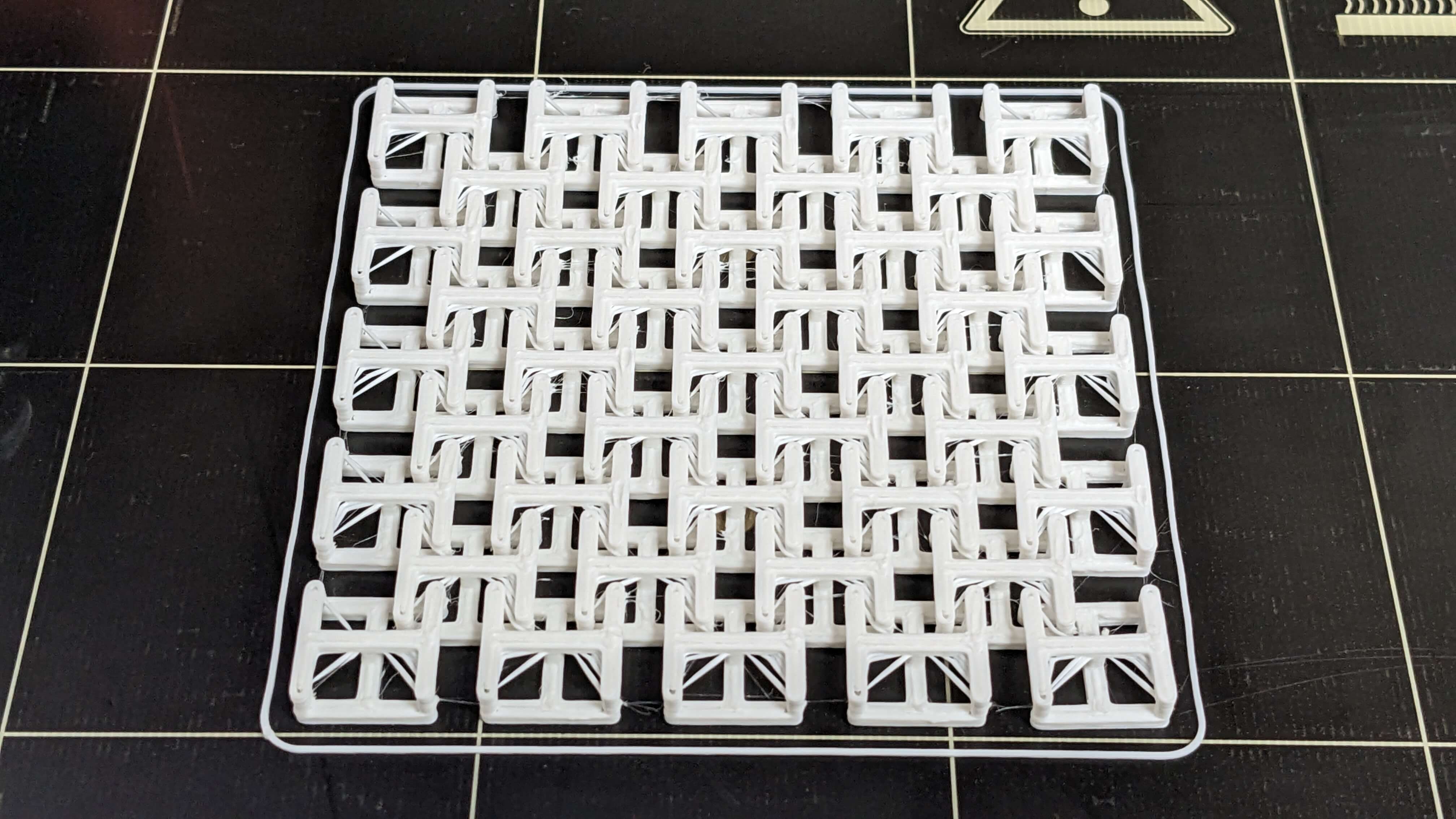
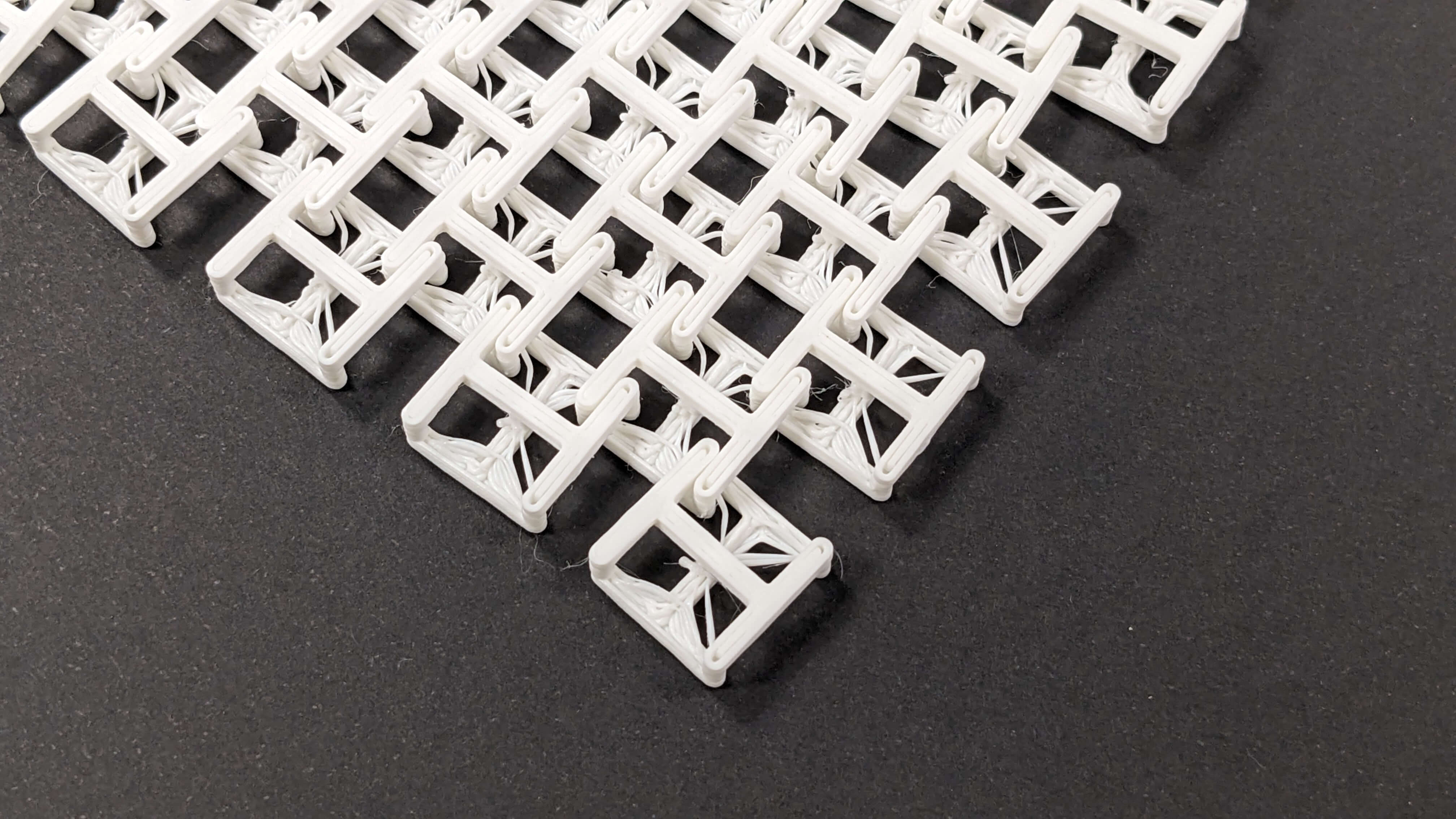
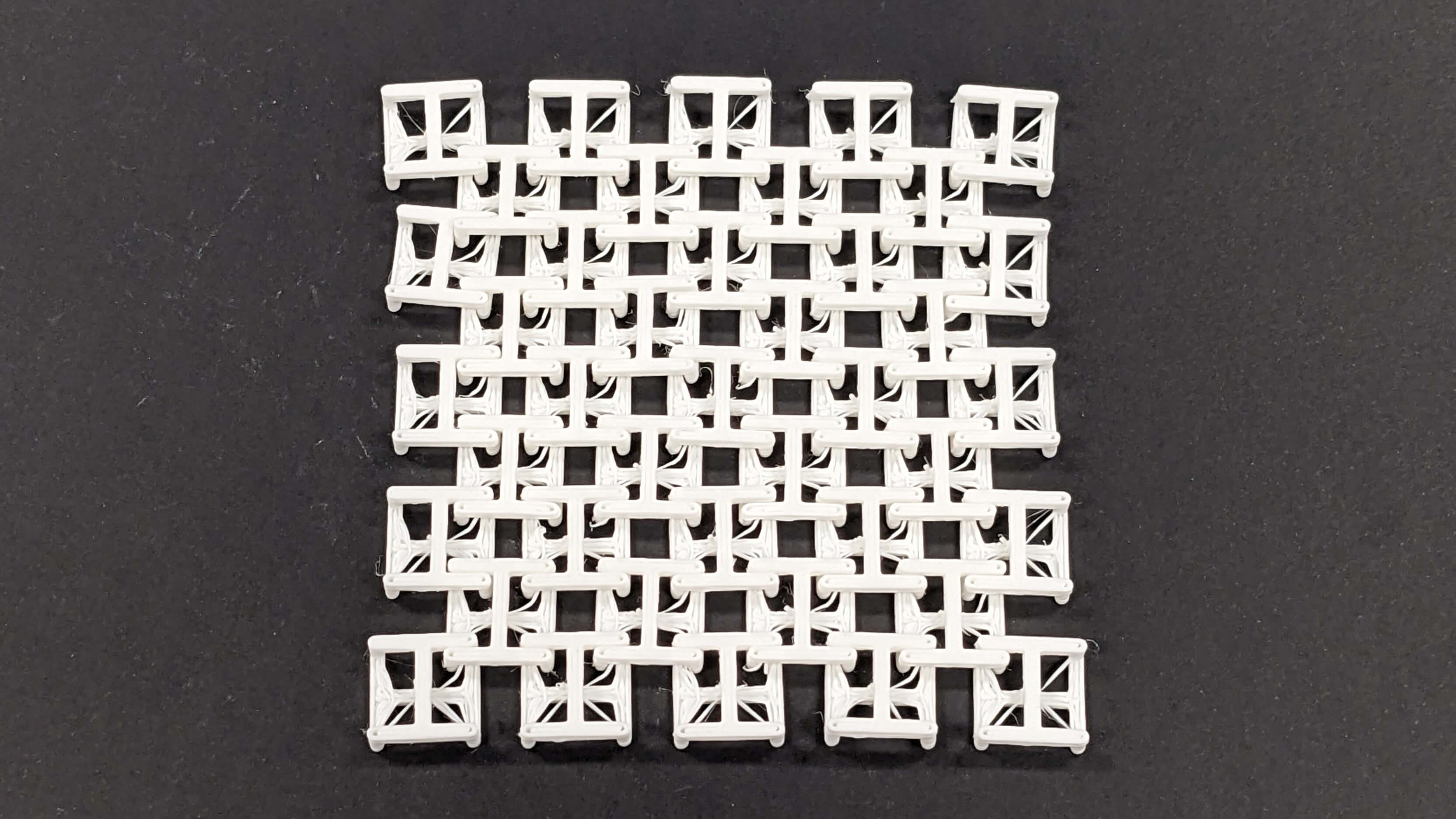
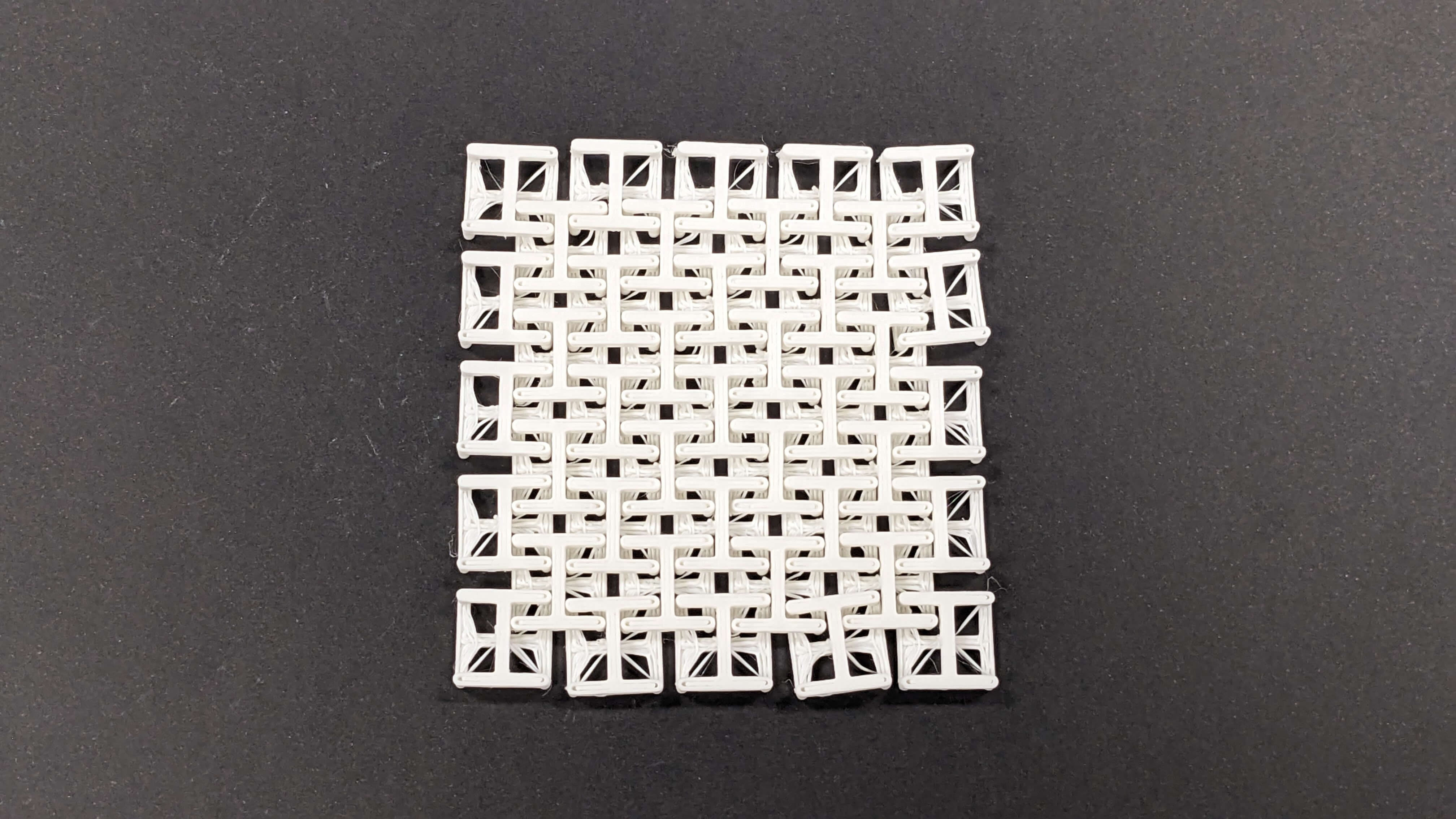
Result
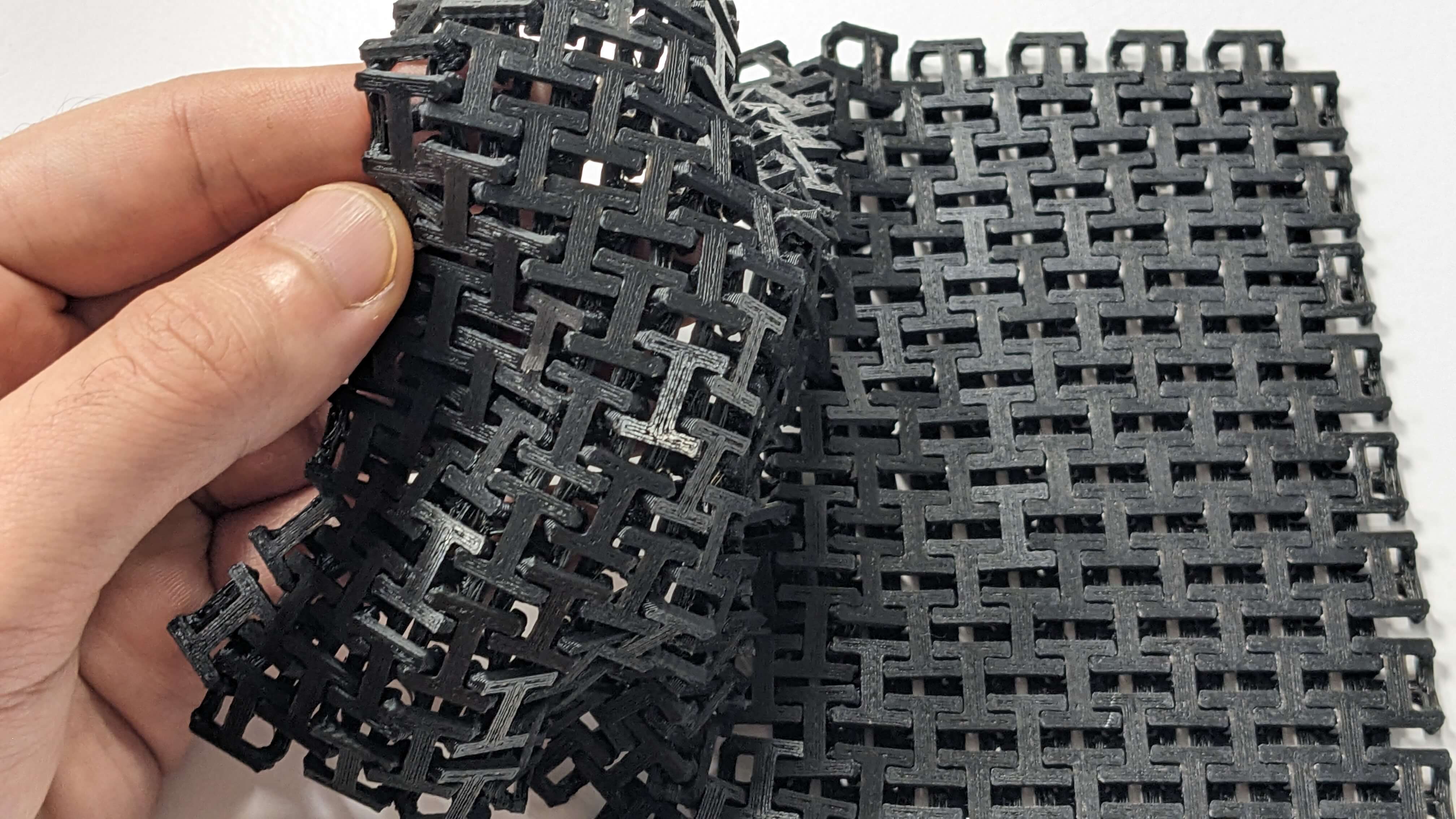
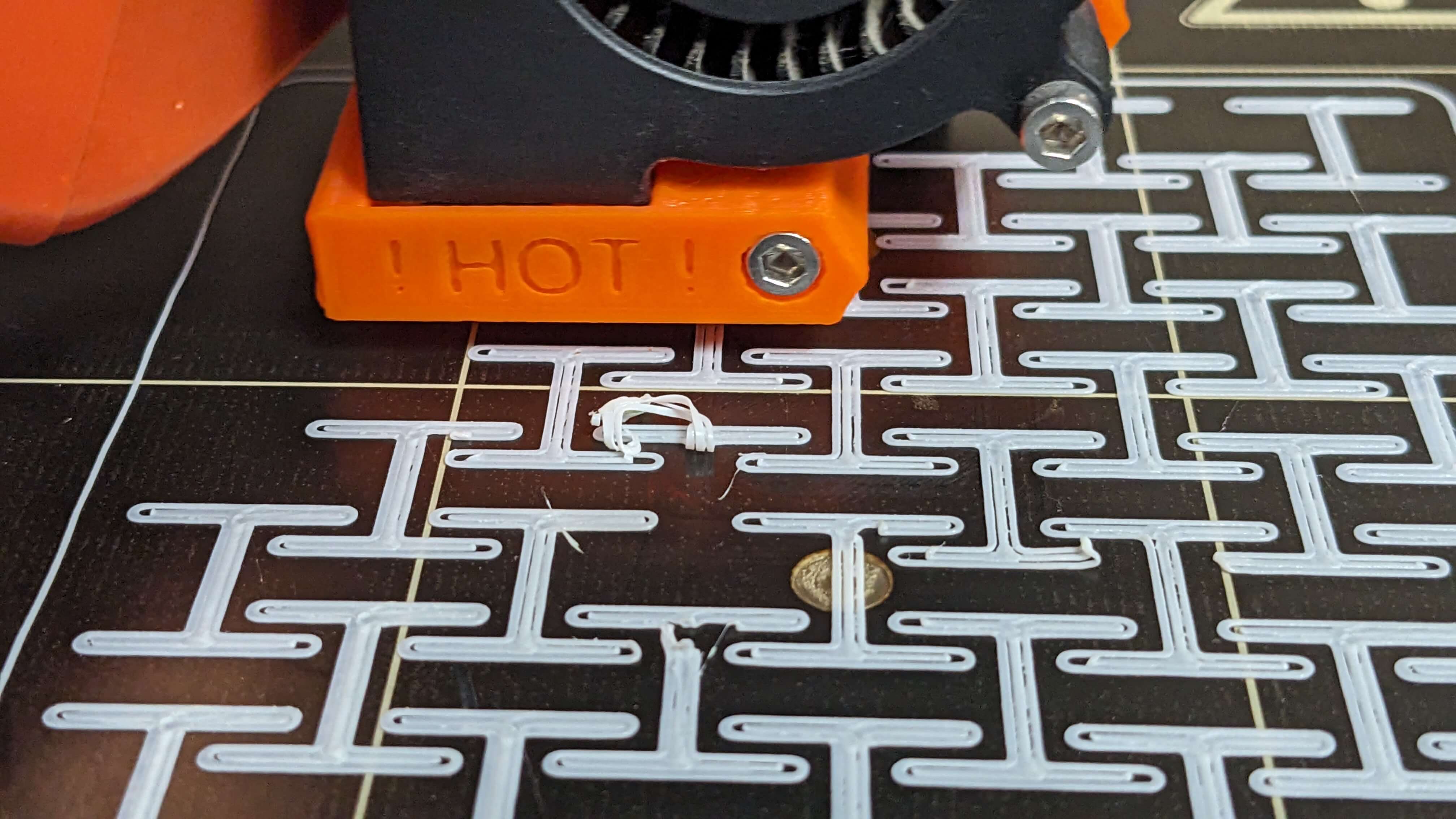
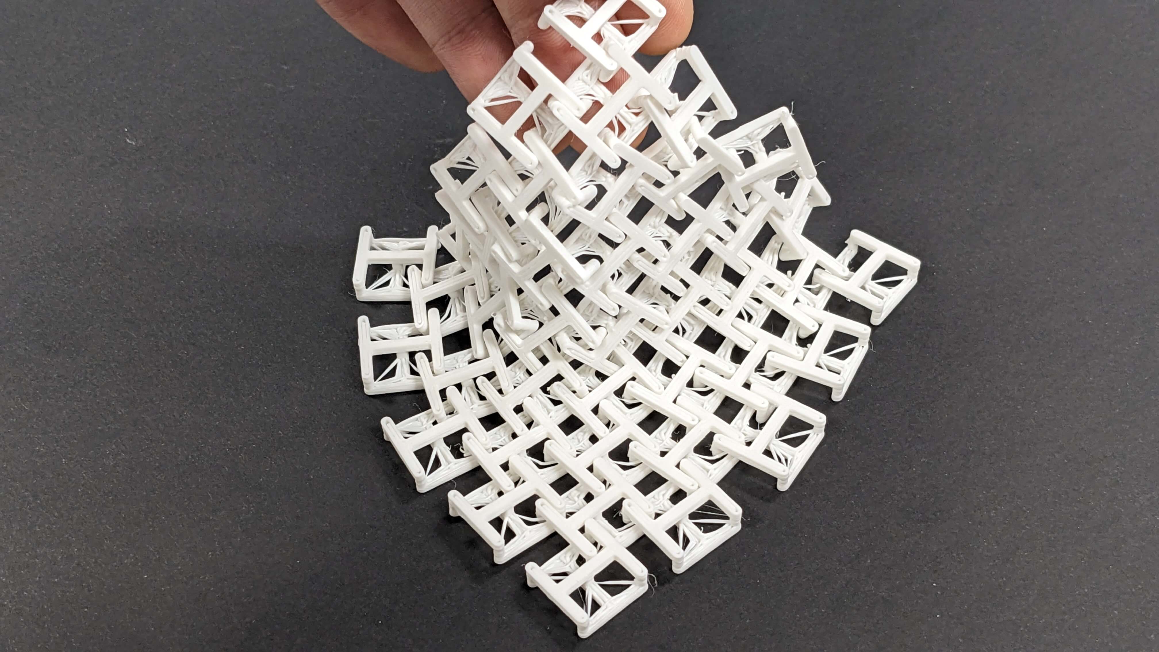
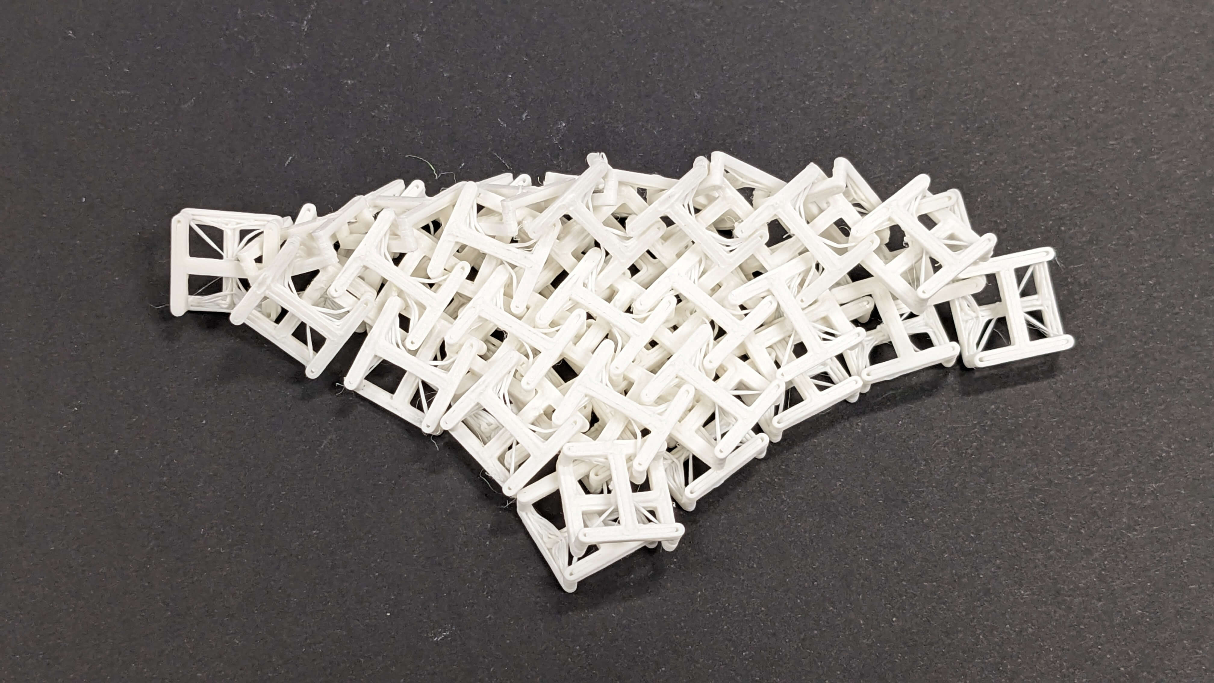
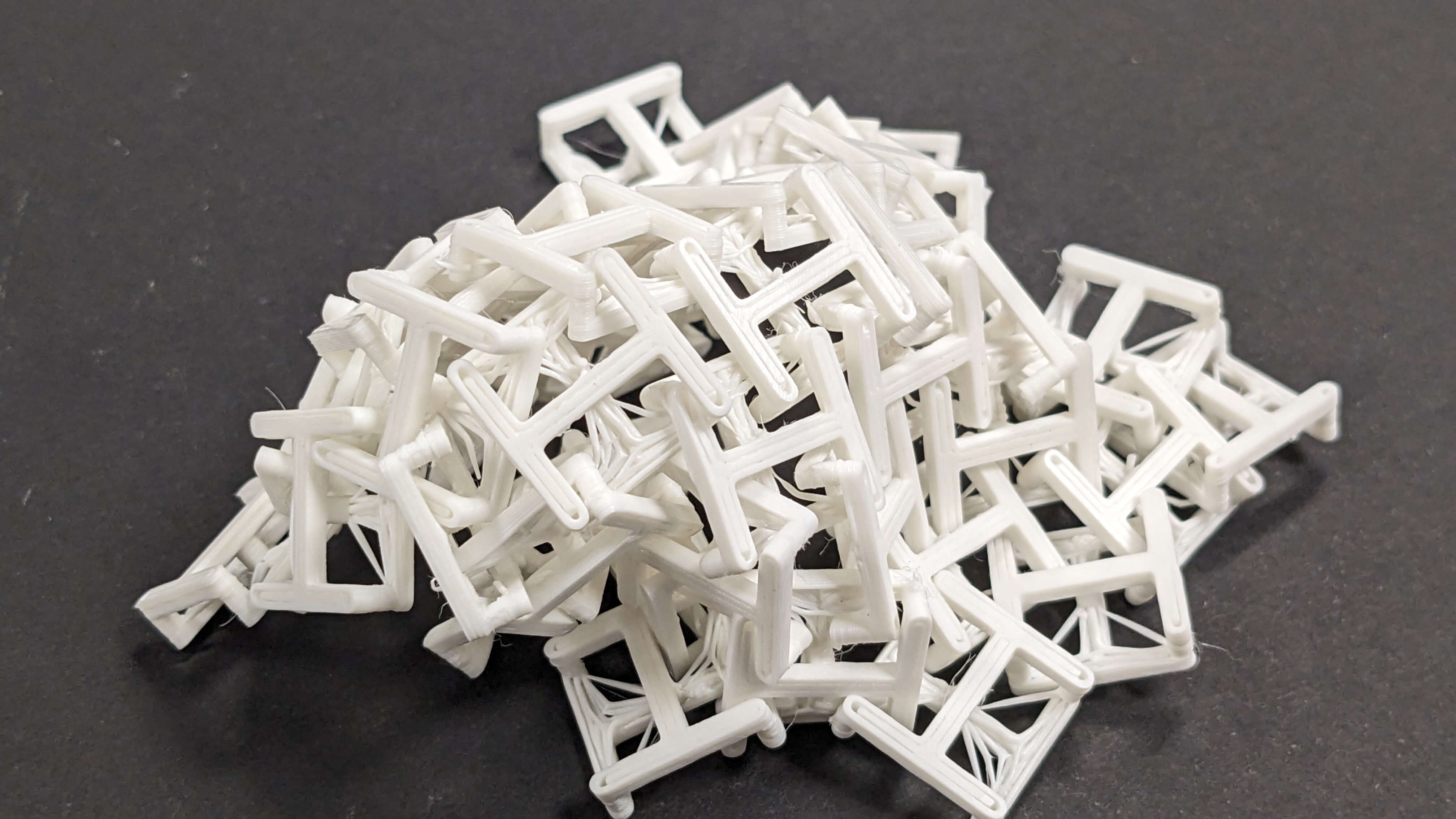
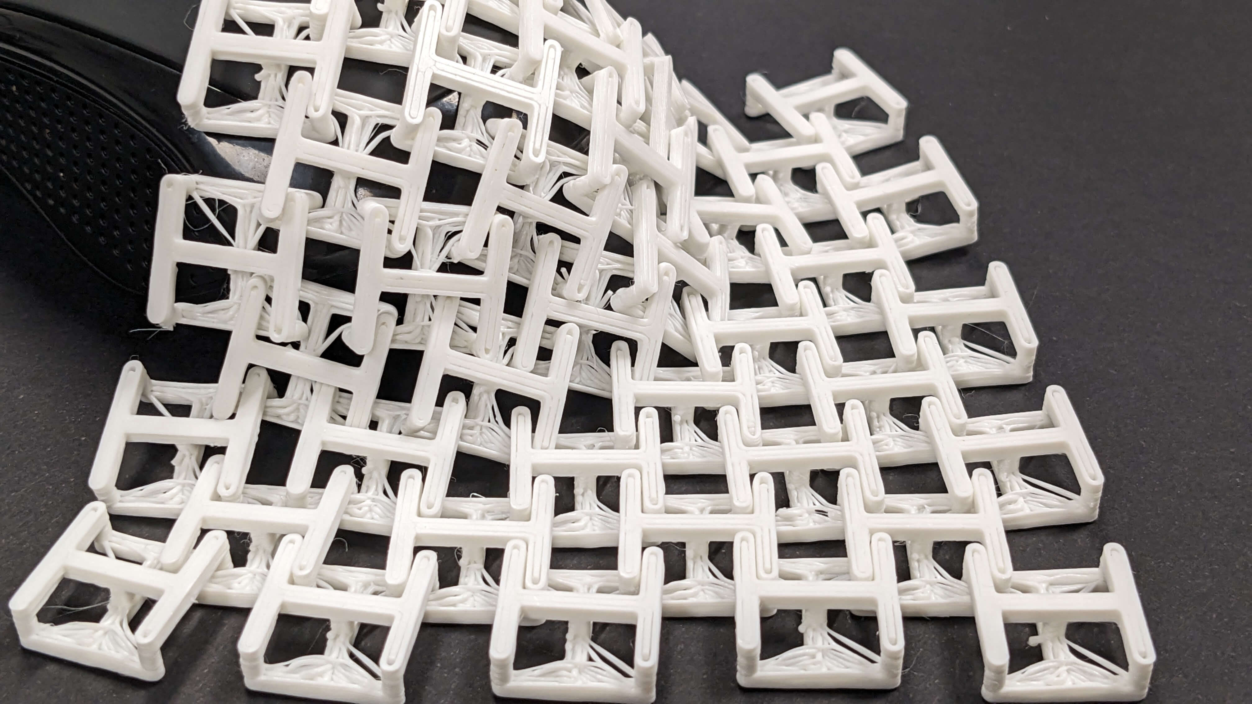
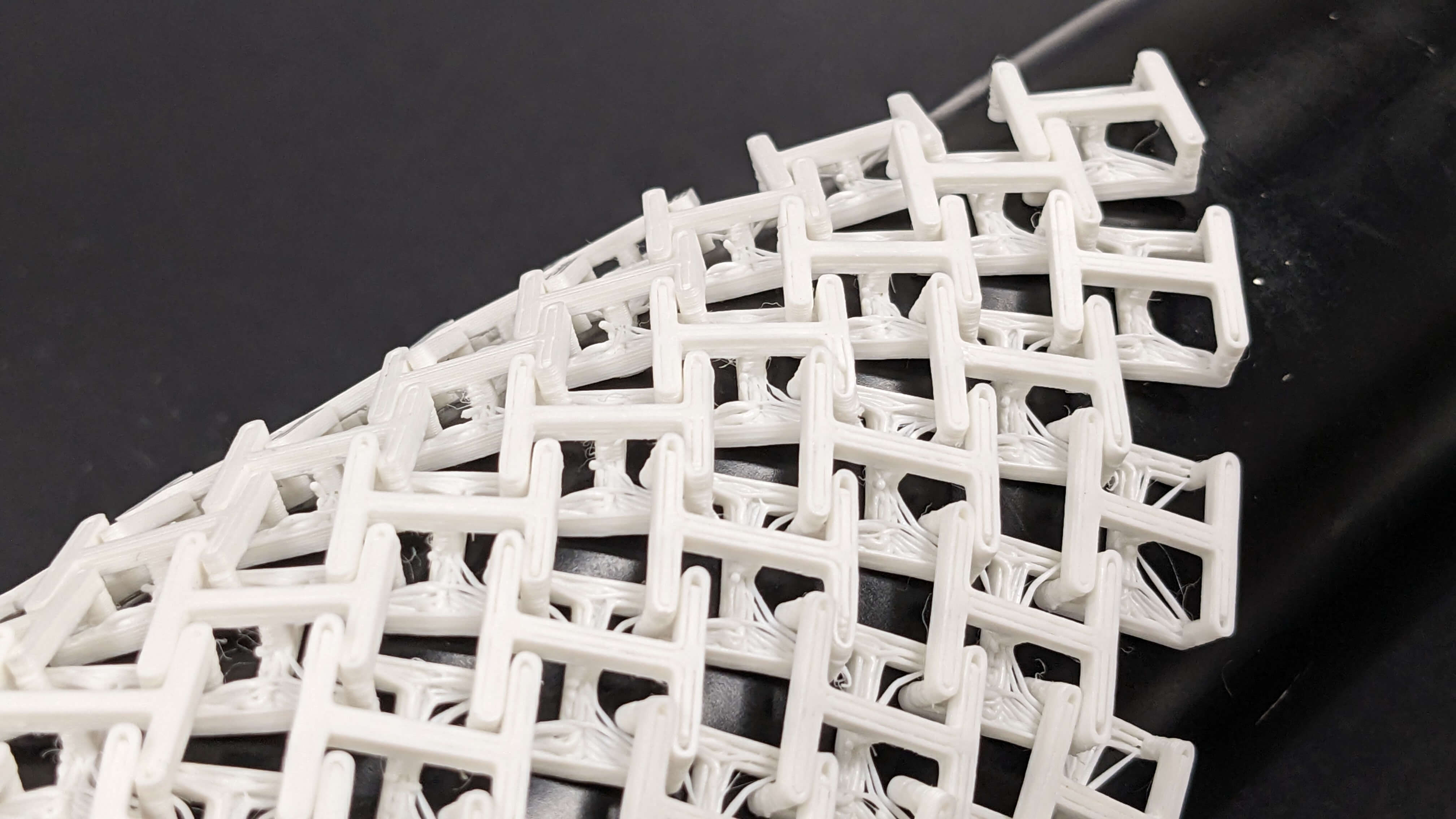
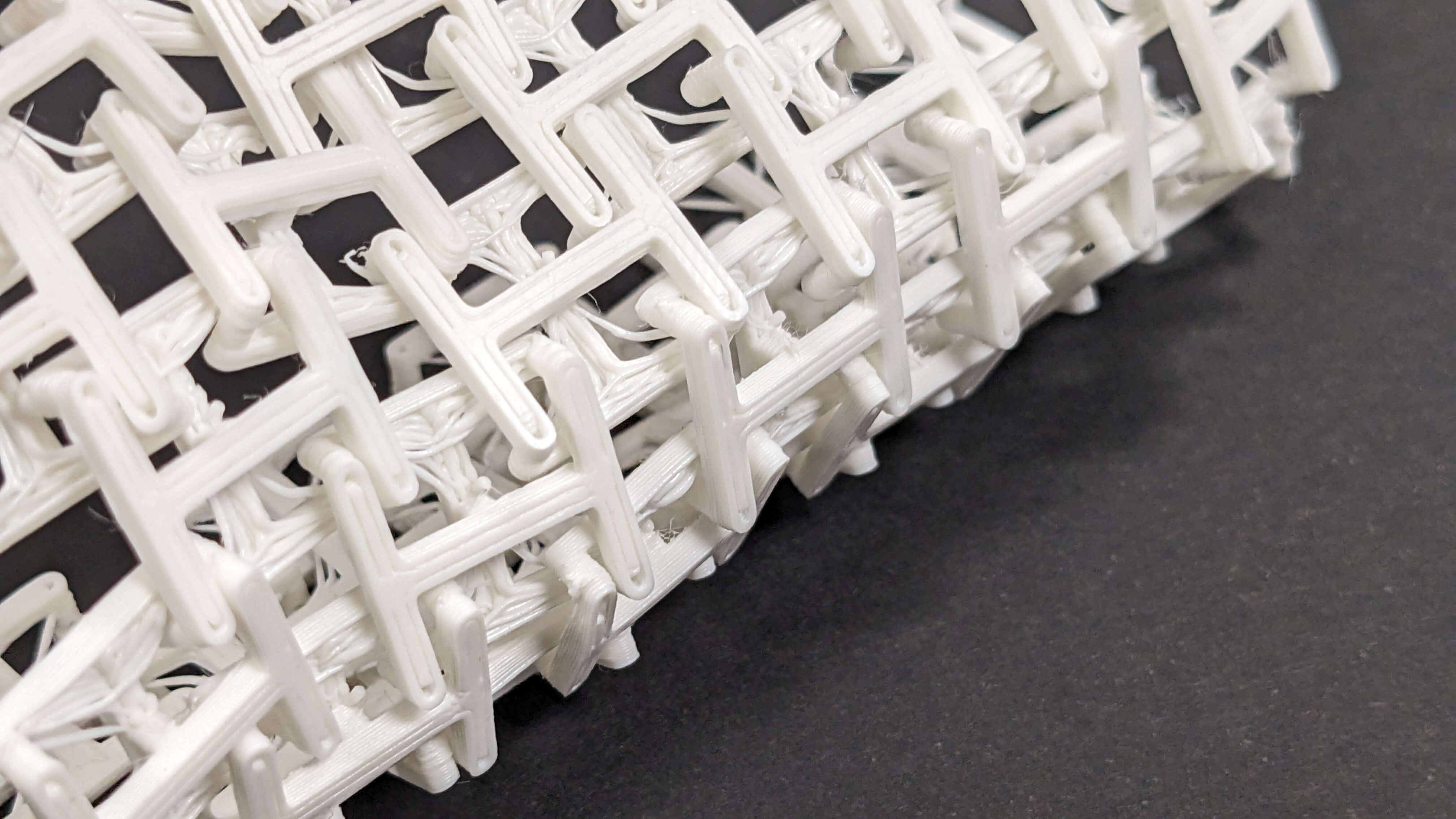
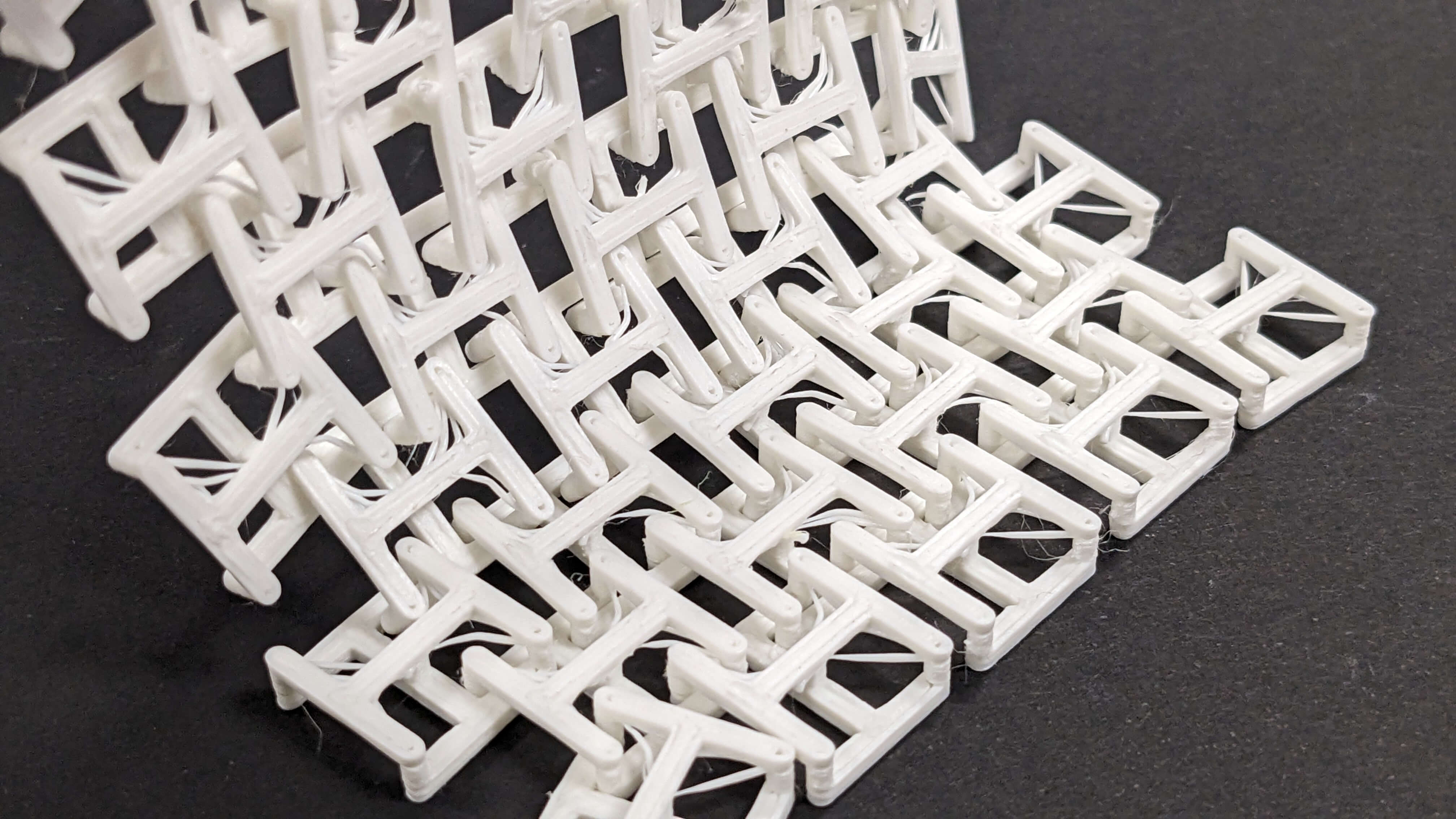
The second trial went well. It was satisfying to take the print off the bed because I could feel thin parts connecting each square are breaking off from each other as they supposed to. The only thing that did not go as I planned was those thin lines in angles. I think this was caused by the amount of filament coming out from the nozzle when it was moving from one point to another, so next time I should adjust the retraction setting.
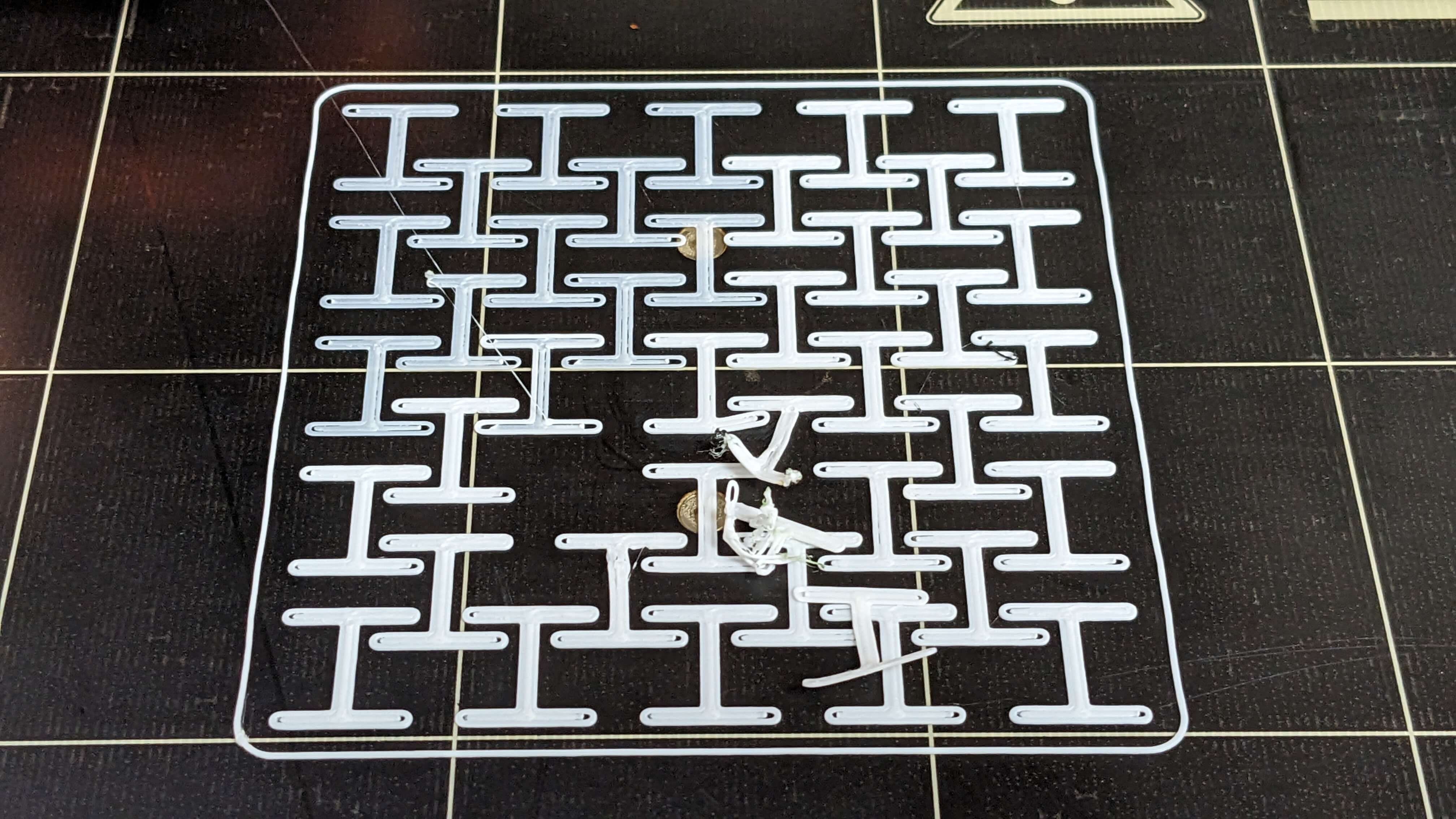
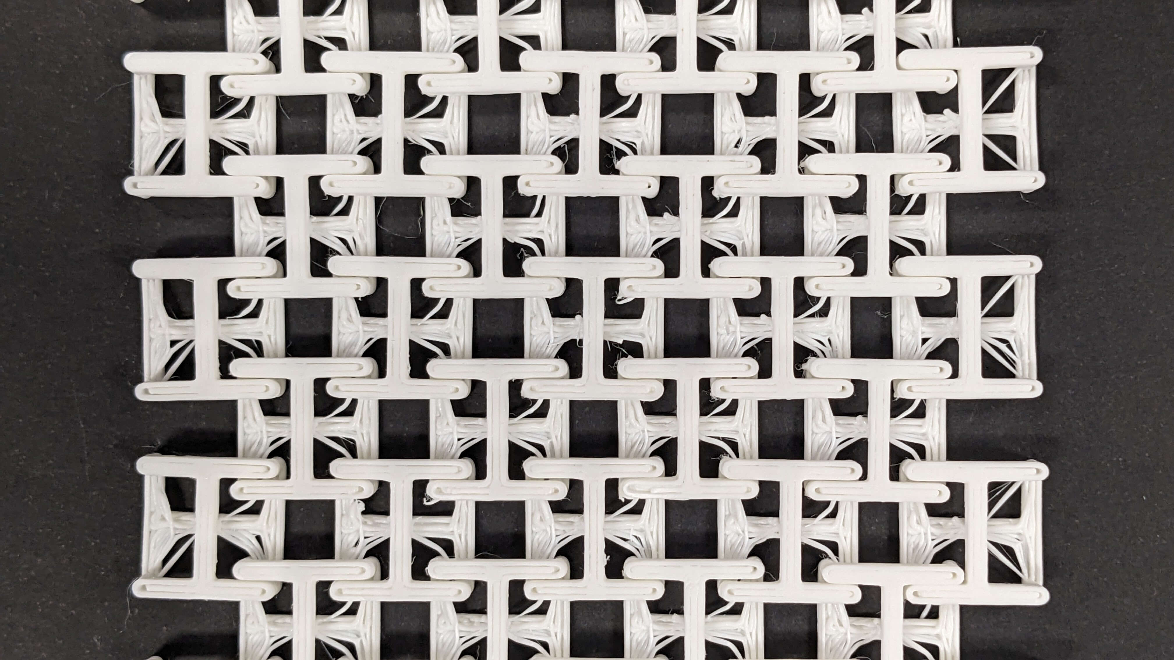
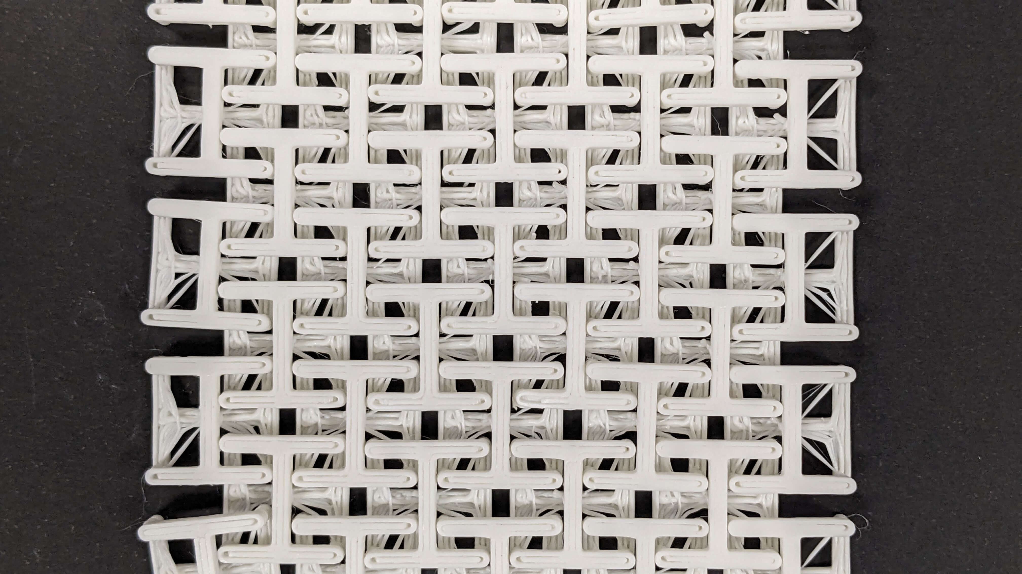
The printed model was interesting to see how the nervous system works. Before printing, I thought the material property was like a flexible surface but as I was playing with the printed model I started to realise that it is more like a chain connected in two directions. I think it was because my printed model had more gaps than the previous model in the connecting part which allows each square to move freely. I think if I play more with the gap spacing and thickness of the square frame, I will be able to add little restriction to the movement. Overall it was a really good experiment to understand the structure and material properties with more possibilities to be explored in the future.
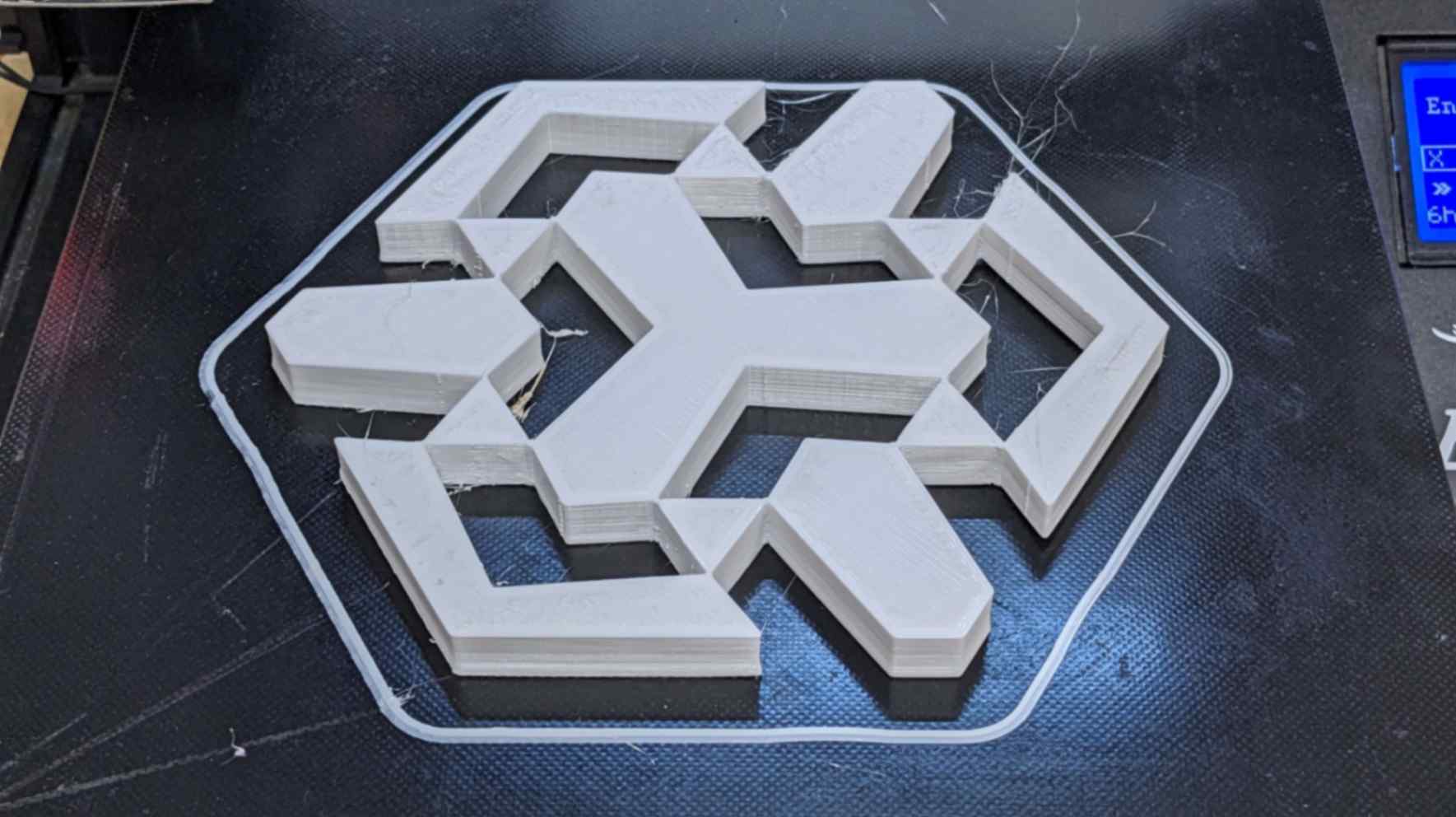
3D Printing: Compliant Mechanism
Because I was advised by my tutor to look into the compliant mechanism for my final project, I wanted to try to 3D print a model which has an element of the compliant mechanism. However it was difficult to understand the principle of the compliant mechanism, so I decided to make a simple shape with the basics of the compliant mechanism.
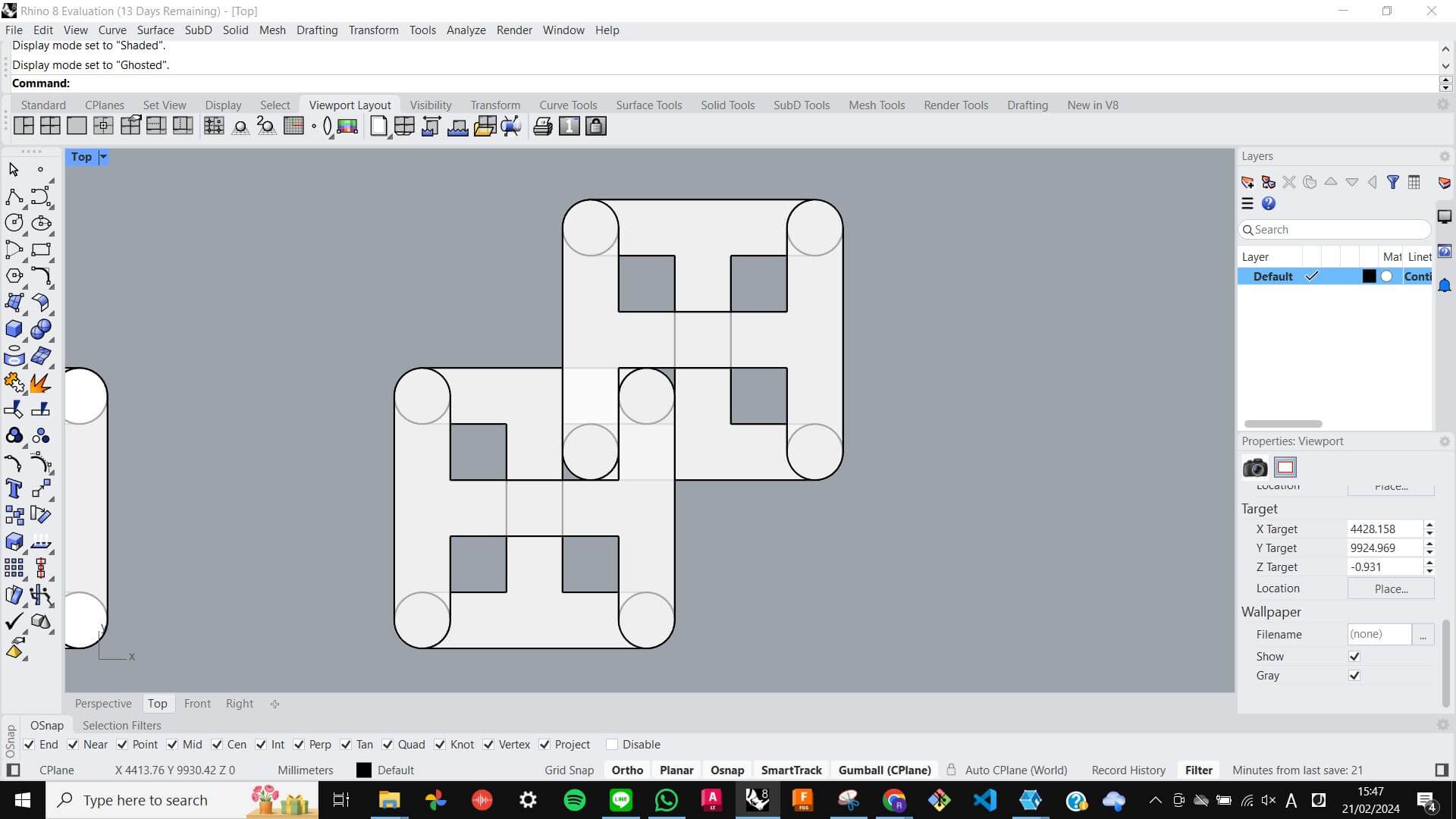
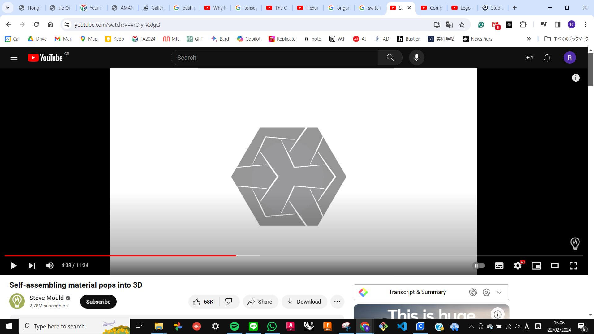
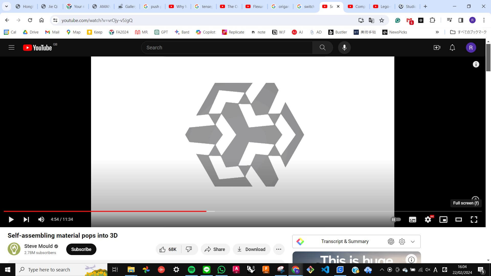
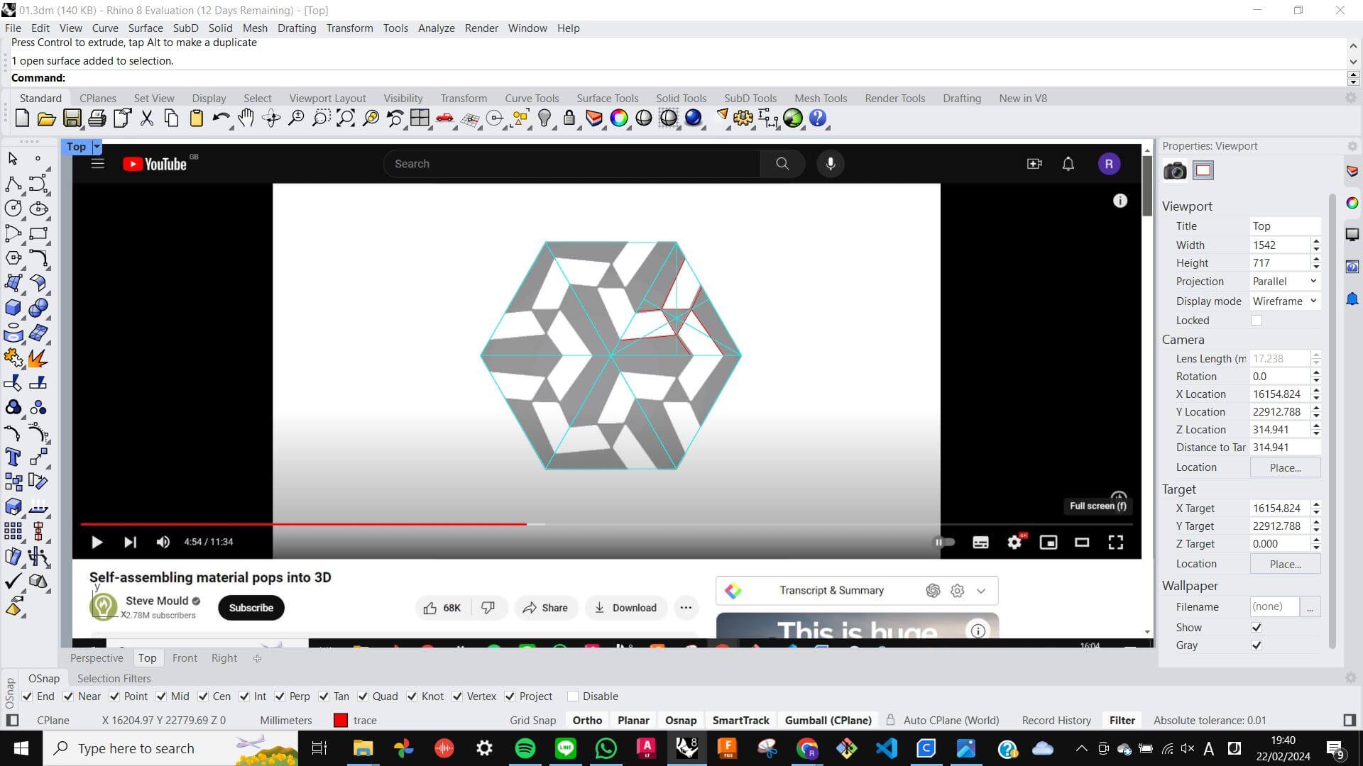
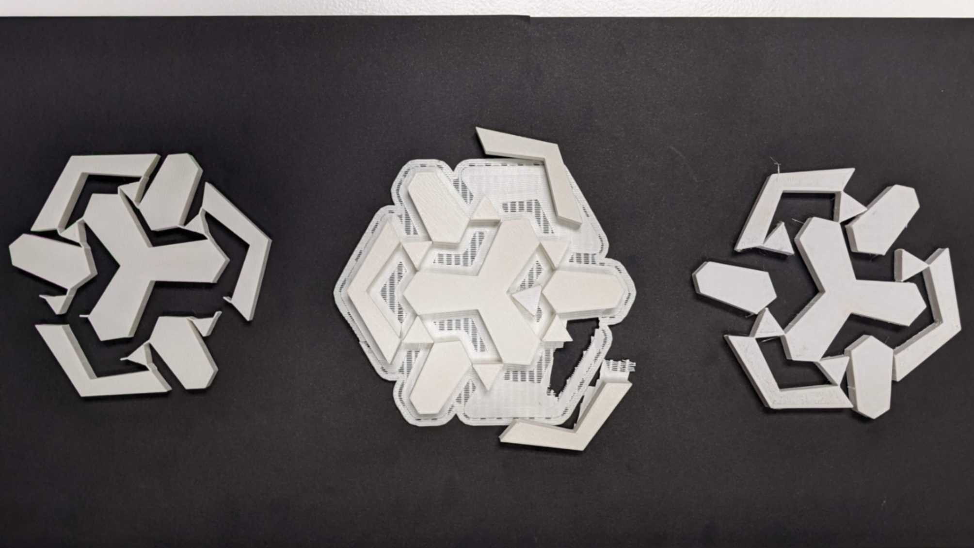
To start, I referred to this YouTube video so that I can clear idea of the basics of the compliant mechanism. I took two screenshots of a pattern when it is open and closed. For 3D printing, the pattern should be printed in an open shape. For the laser cutting, the pattern should be cut in a closed shape.
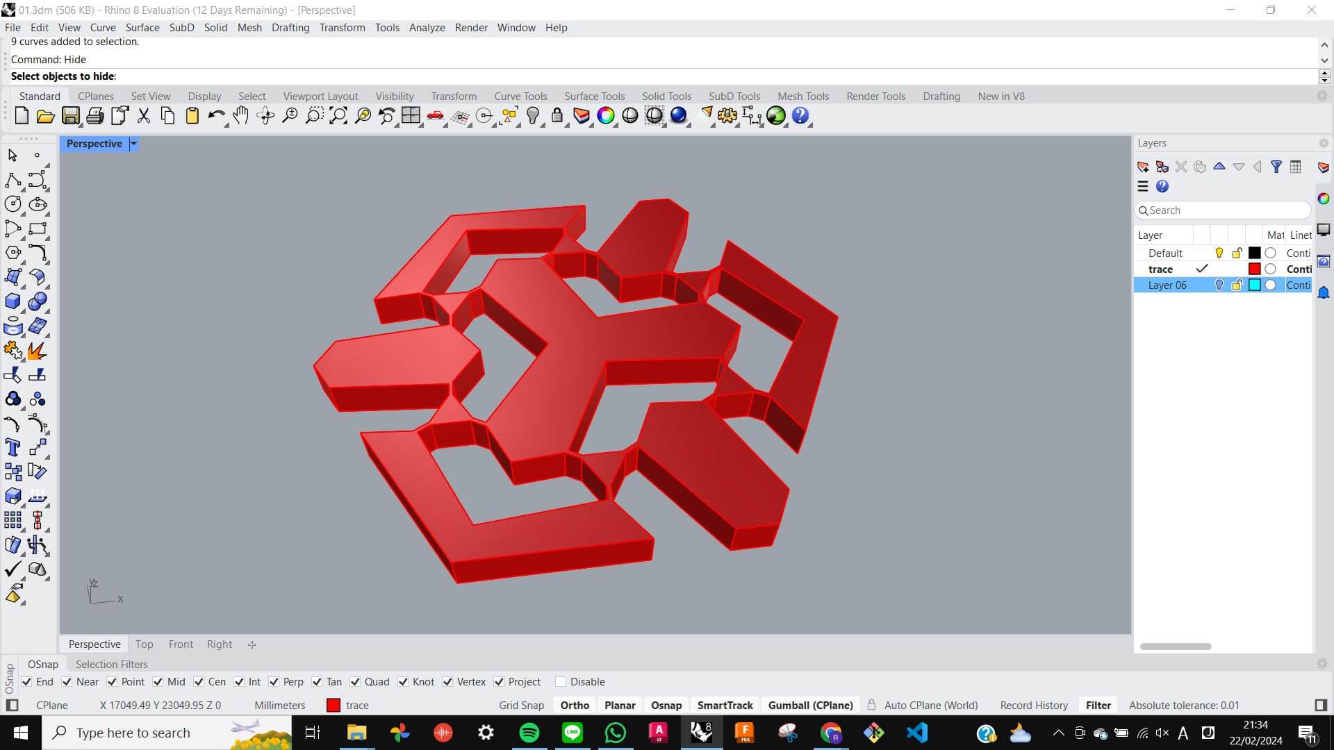
Modelling
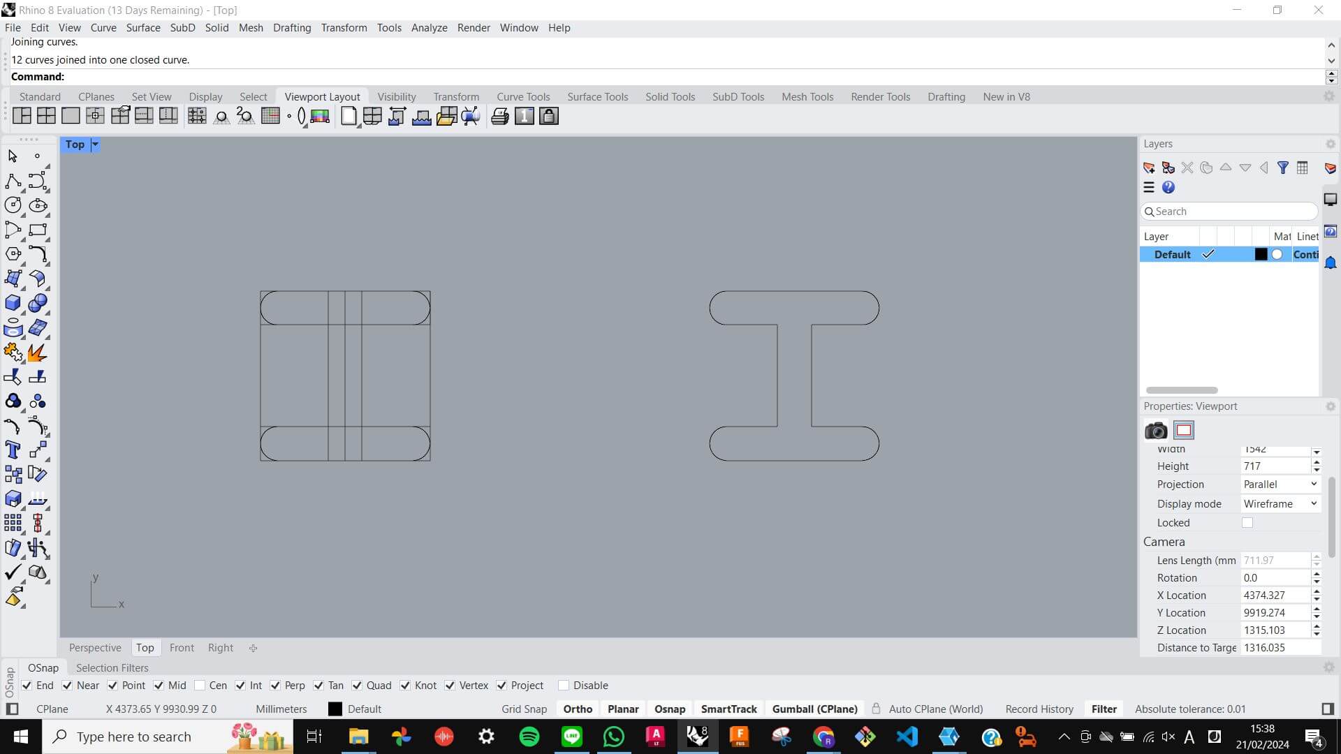
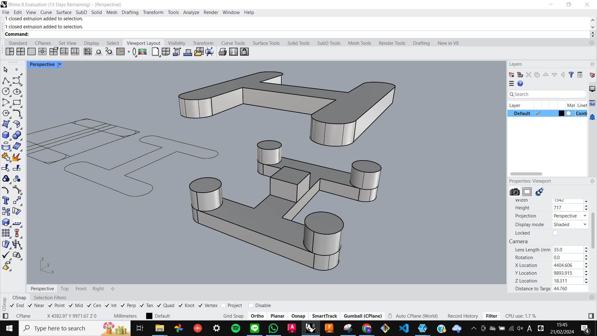
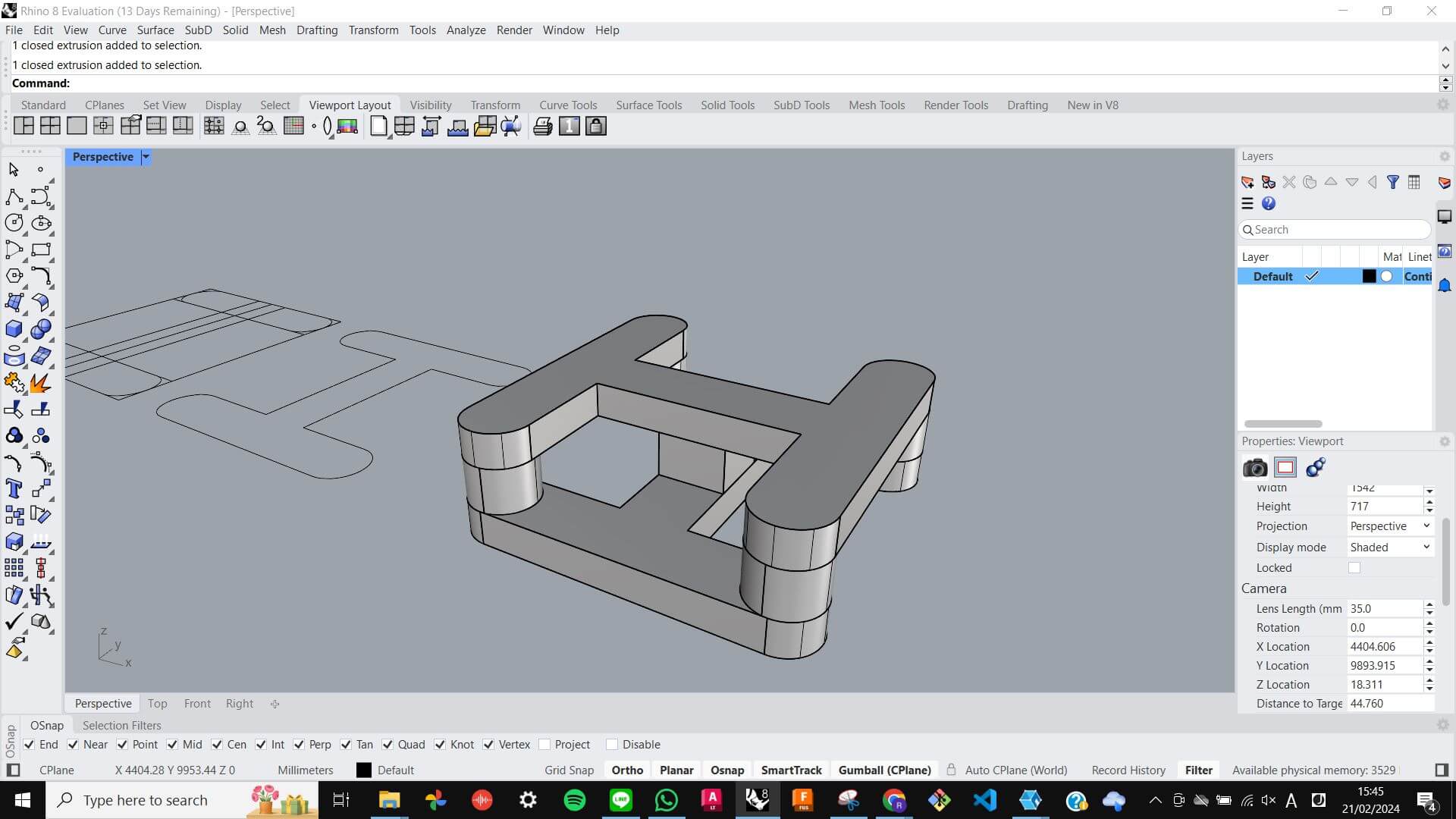
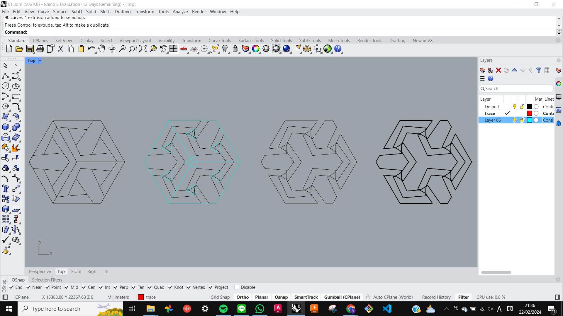
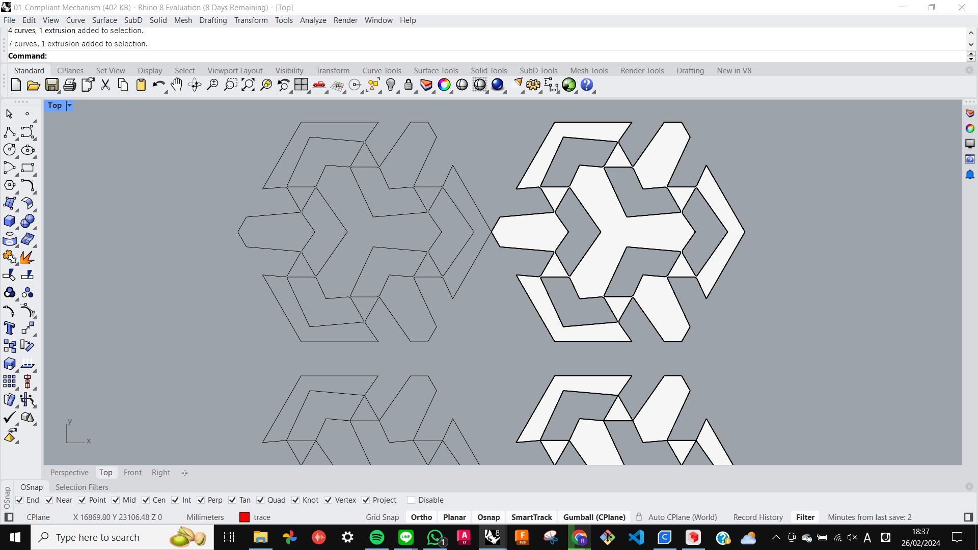
Then I tried to replicate it in Rhino just by looking at it. However I experienced a hard time drawing without the same scale and dimension, and I was not able to get the result that I wanted.
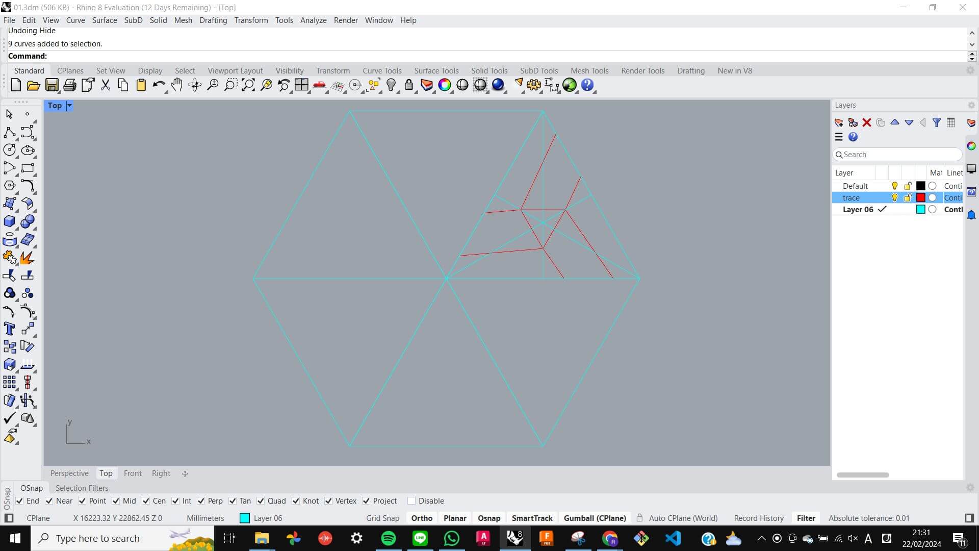
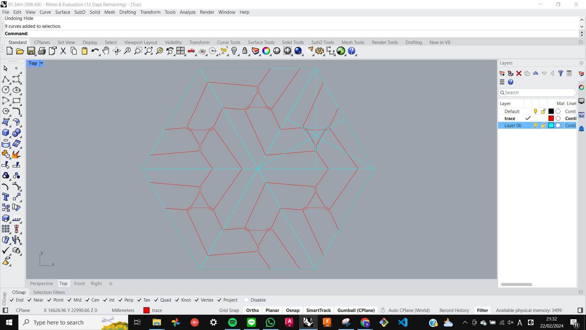
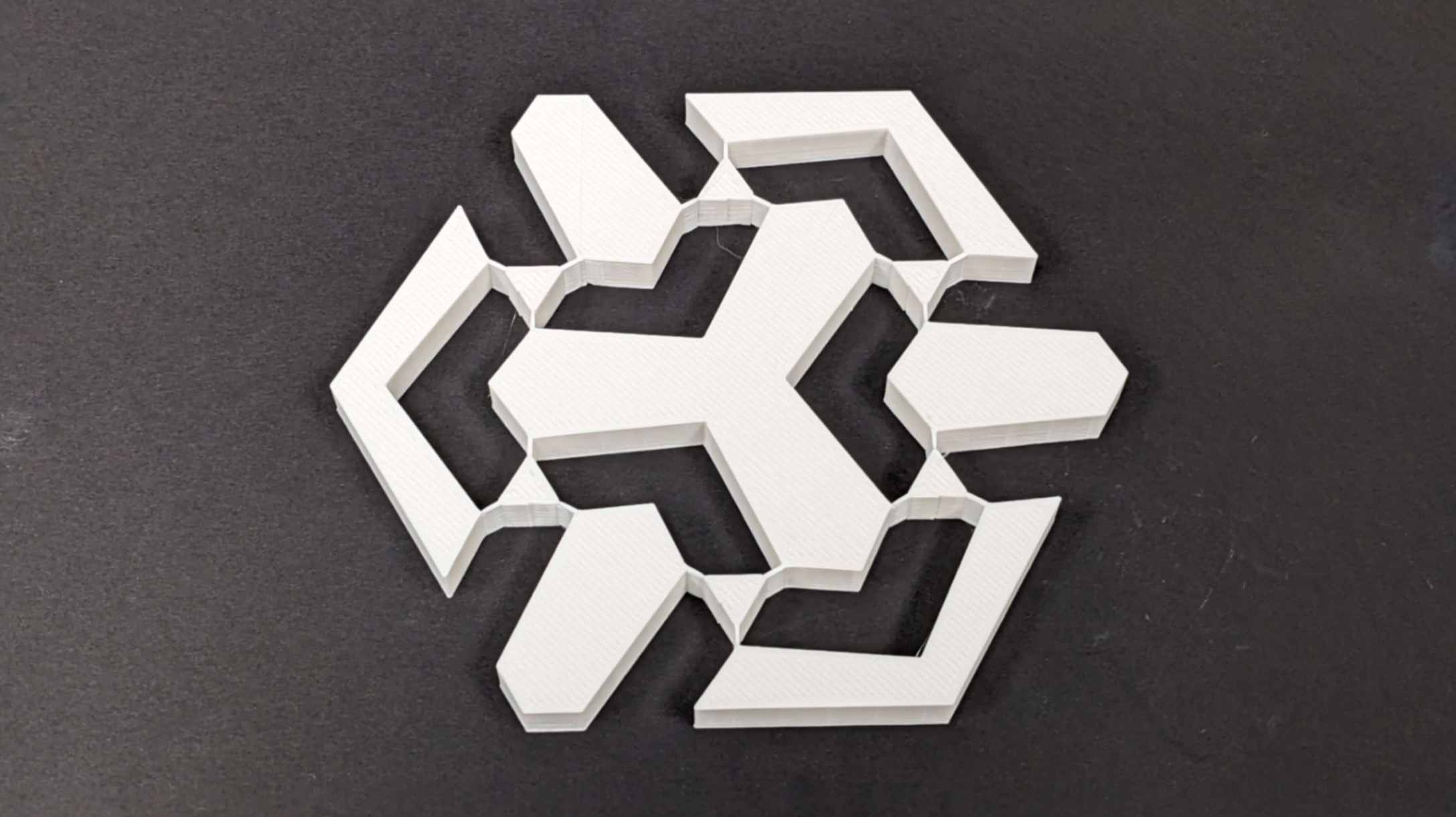
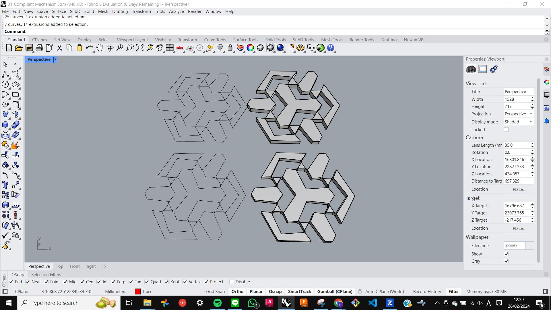
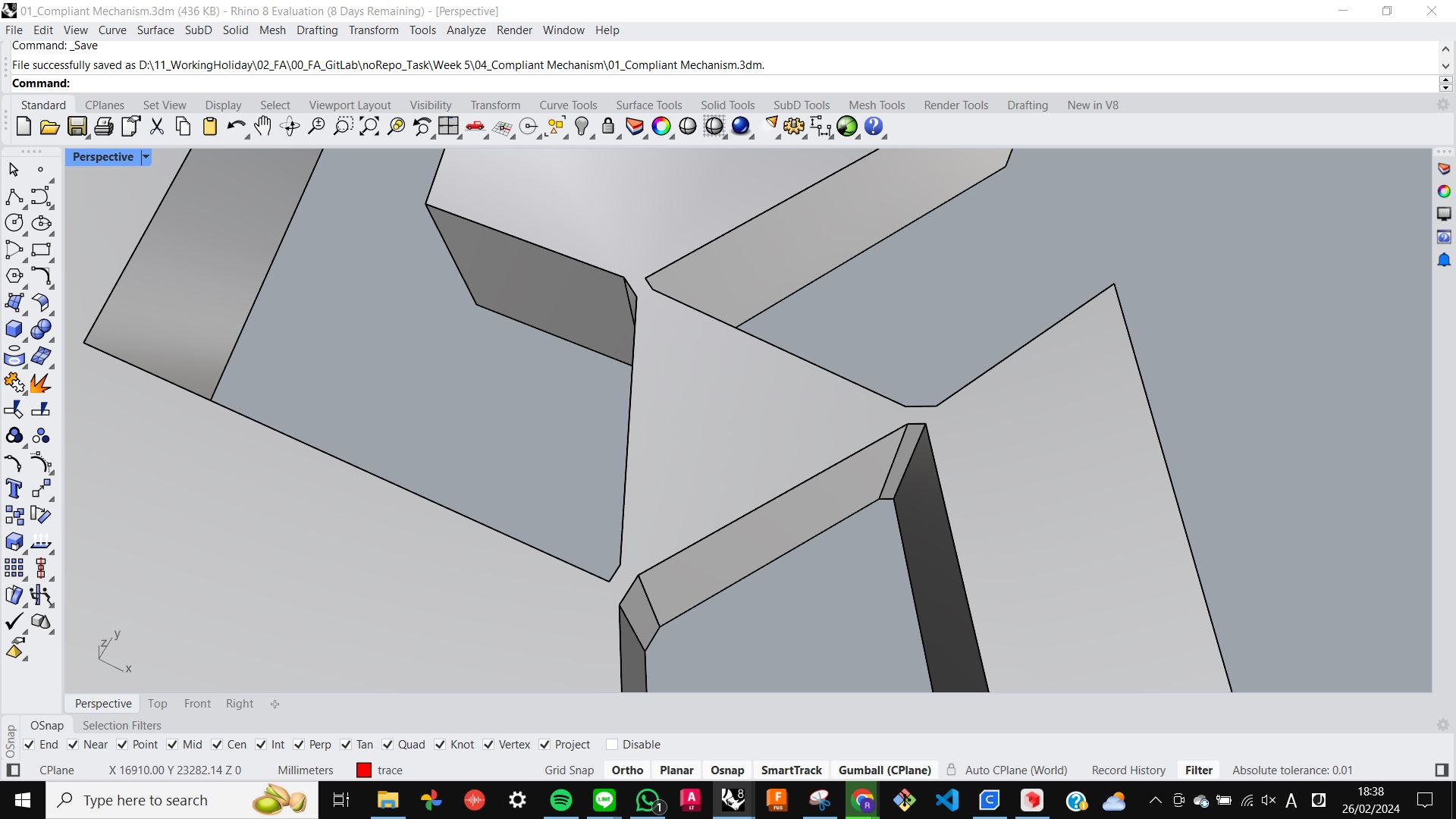
So I decided to redo it from scratch, but this time I started by importing an image in Rhino and tracing on top of it. As I was tracing I started to understand the design rule of making this pattern, and what was wrong with the previous trial. Before I was focusing on the centre point and the grid of the shape, and I missed out on the fact that the shape is hexagonal which is simply a circular array of triangles. After I realised that I focused on a triangle and started to draw what was inside of the triangle. This made me understand clearly the design rules of this pattern and eventually, I was able to draw the pattern I wanted.
Files01_Compliant Mechanism.3dm
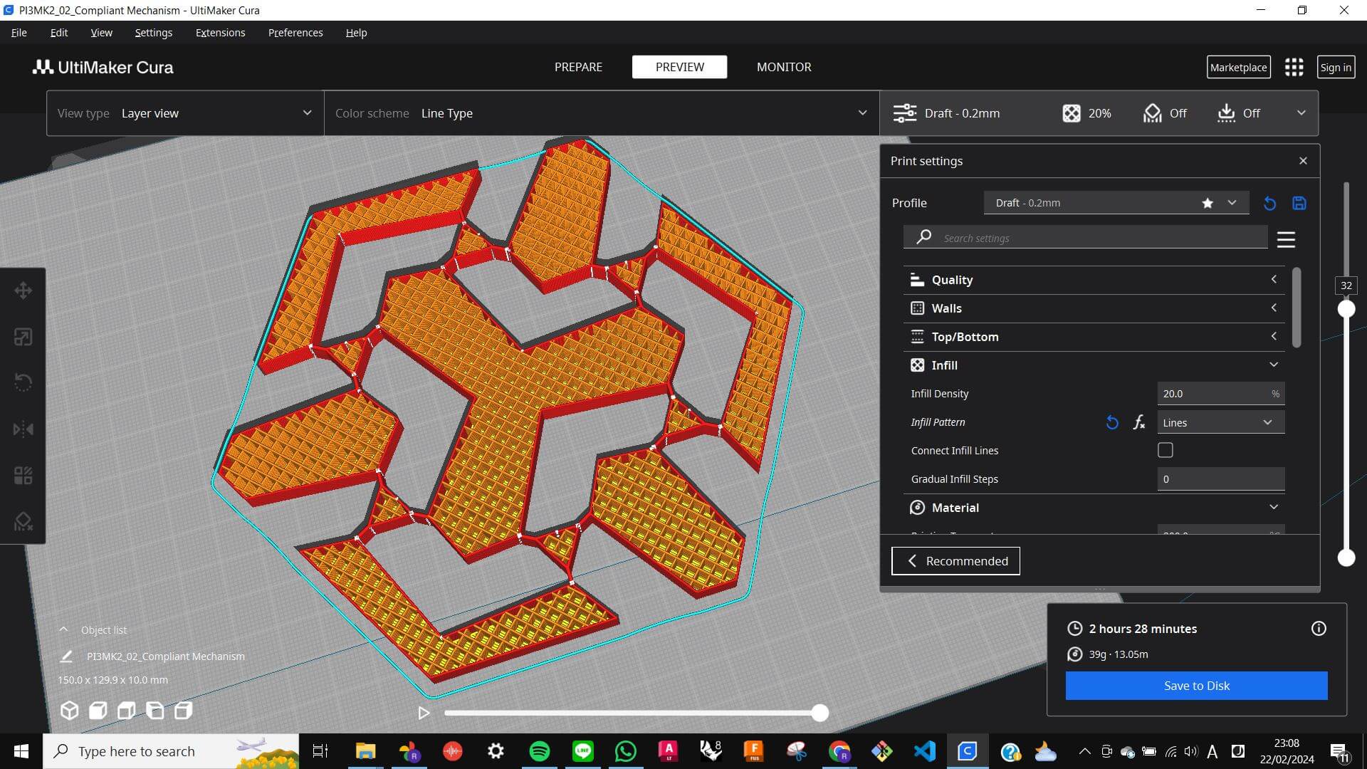
Slicing
After achieving the pattern I simply extruded for 10mm and transferred the file to Cura. I used Prusa i3 MK2 same as last time This time in Cura, I used an advanced print setting. The only thing I set differently from the previous 3D print was the Printing Temperature to 200, Print Speed to 80, and Infill to Lines 20%.
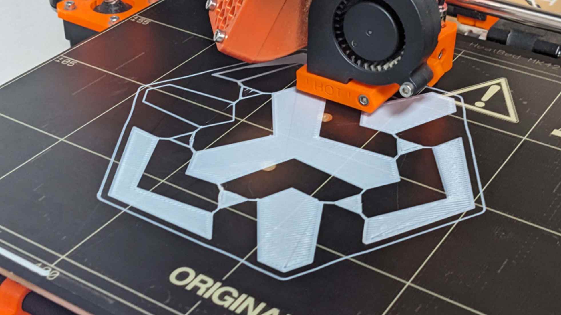
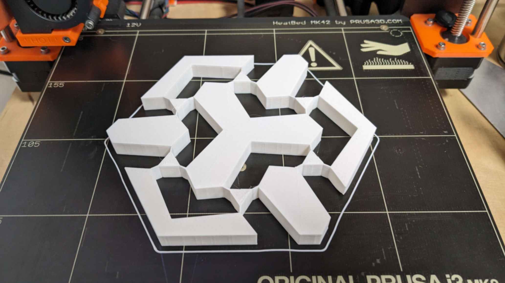
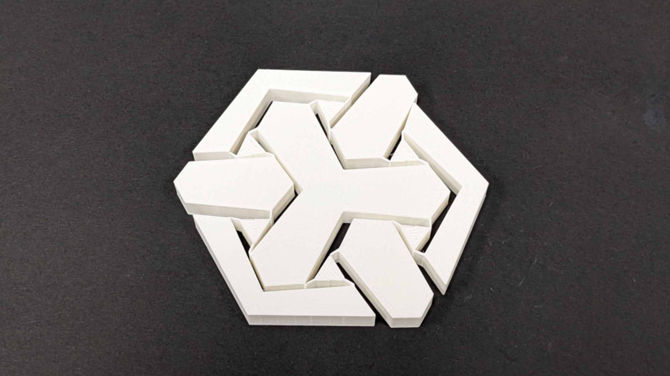
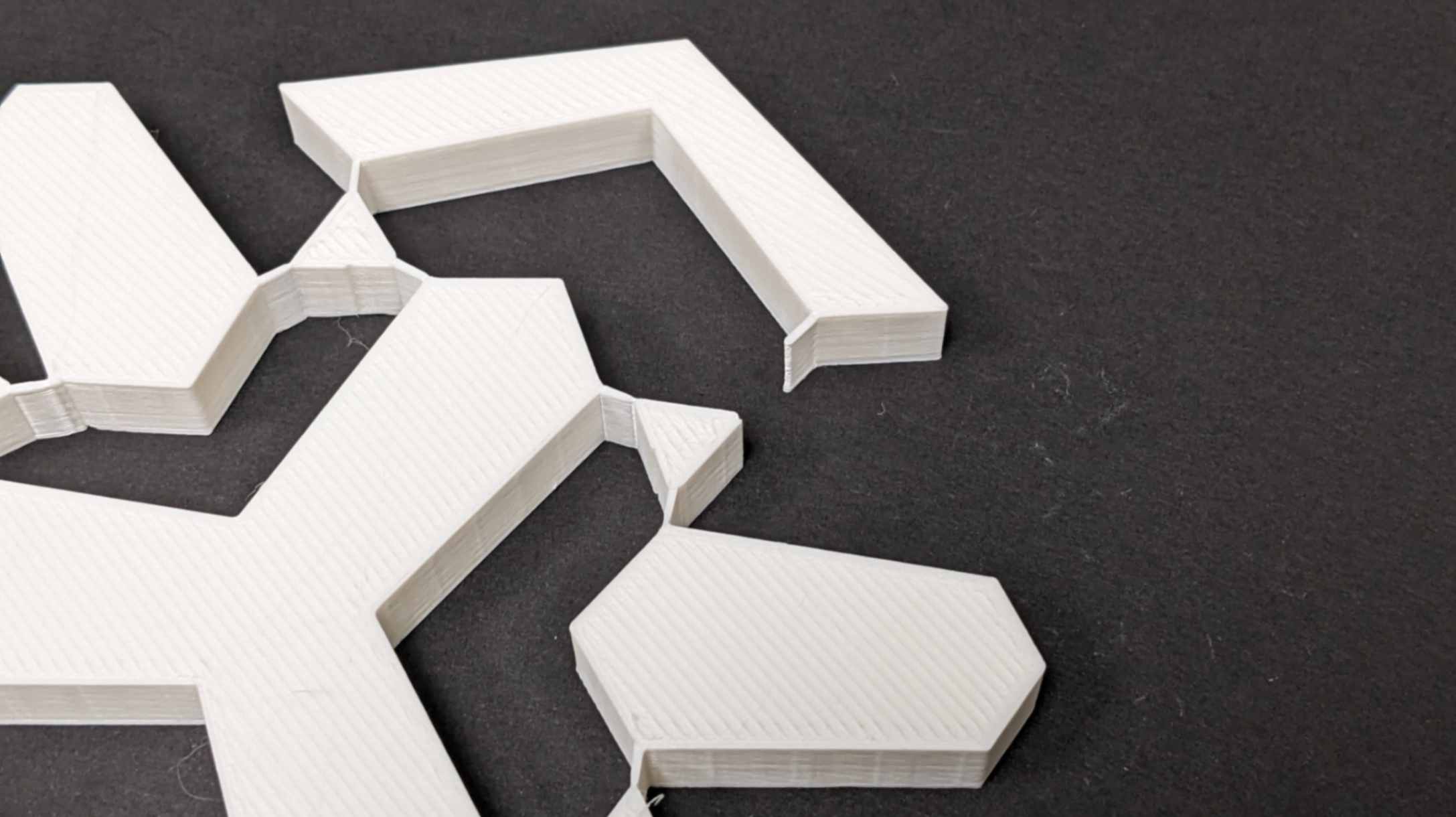
Result
As a result, it printed as I wanted to print, and I was able to squish the shape as it was supposed to move. However, after a couple of squishing, the triangle hinge parts broke. I think it was because the connecting parts were too thin and too long and also the material properties of PLA were not strong enough to take the stress when it was squished. At least it was a good experiment to get an understanding of the feeling of the compliant mechanism when it moves.
Files01_Compliant Mechanism_PRINT.stl
2nd Trial
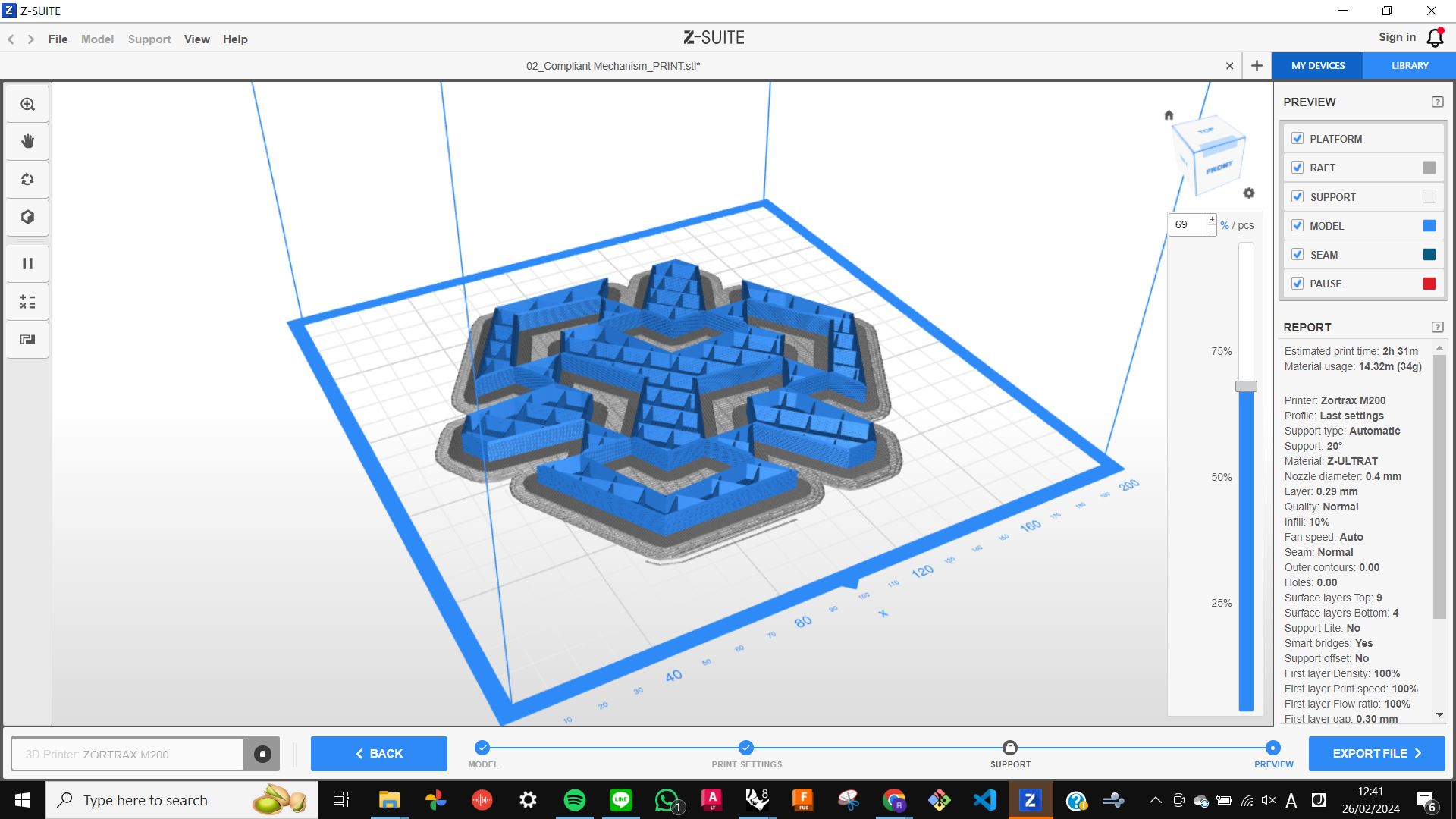
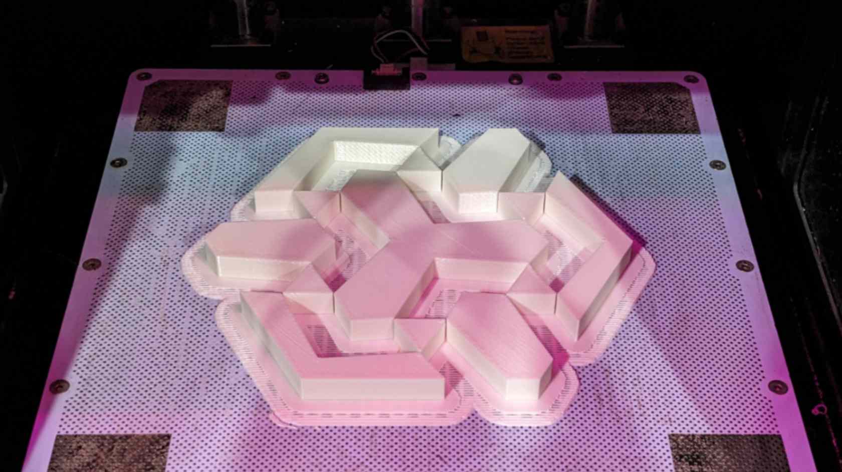
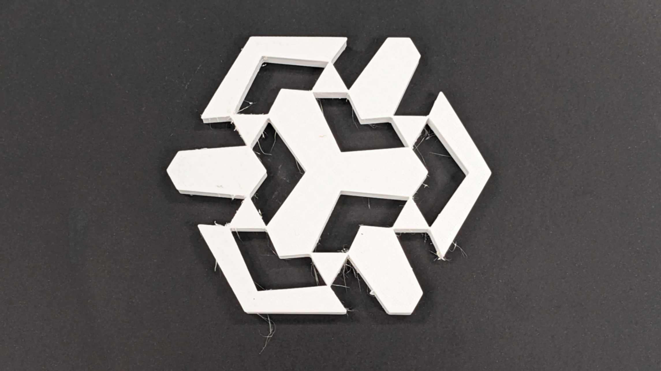
I wanted to take the compliant mechanism experiment further, so as a 2nd trial I wanted to 3D print the shape with stronger material. This time I decided to print with Z-ULTRAT on a Zortrax M 200 printer. Also, this time I made the shape with a bigger triangle hinge, just touching other components with a single point.
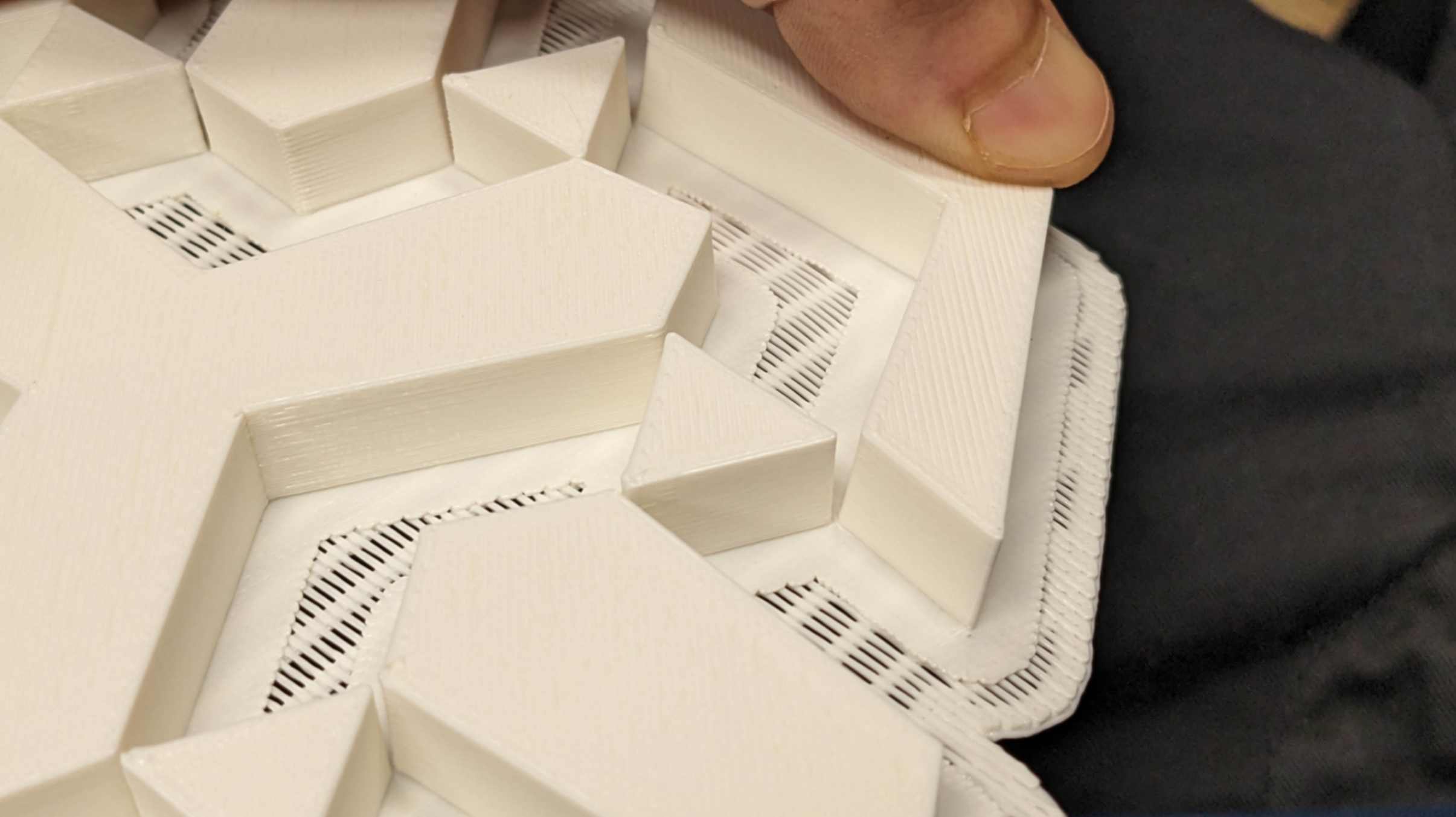
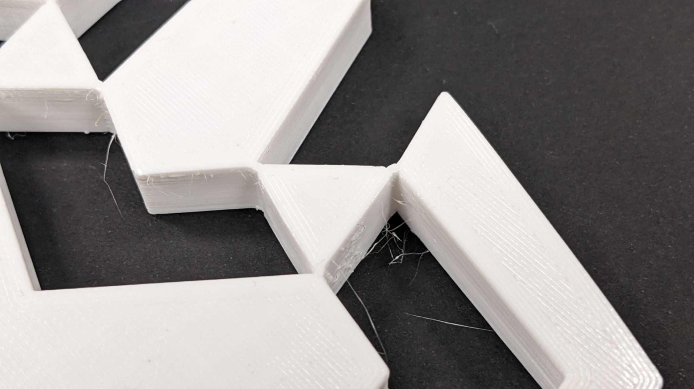
Result
As a result, the print looked clean, but the triangle hinge was detached from other components. Since it was all components were not connected it did not work as the test for a compliant mechanism. The lesson I learned from this is that I should have made the model connected to all the components even though it is touching the surface because the printer detects the shape as different components. To be honest this was a very easy mistake and I should have thought about it more about the design rule of printing.
Also, the raft that I printed was very hard to remove. I need to consider adjusting my setting for the thickness of the raft and the distance from the first layer more next time.
Files02_Compliant Mechanism_PRINT.stl
3rd Trial
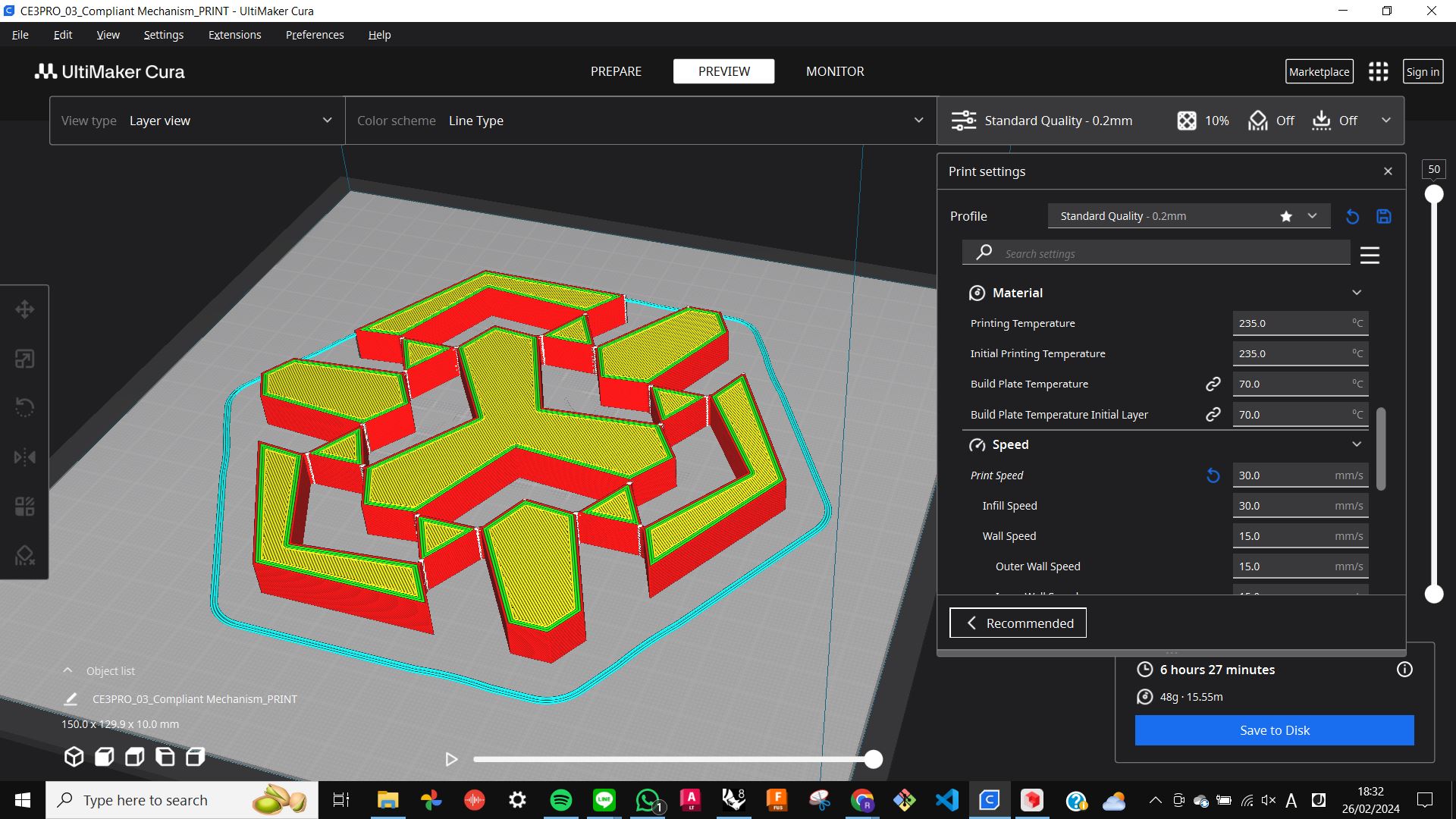
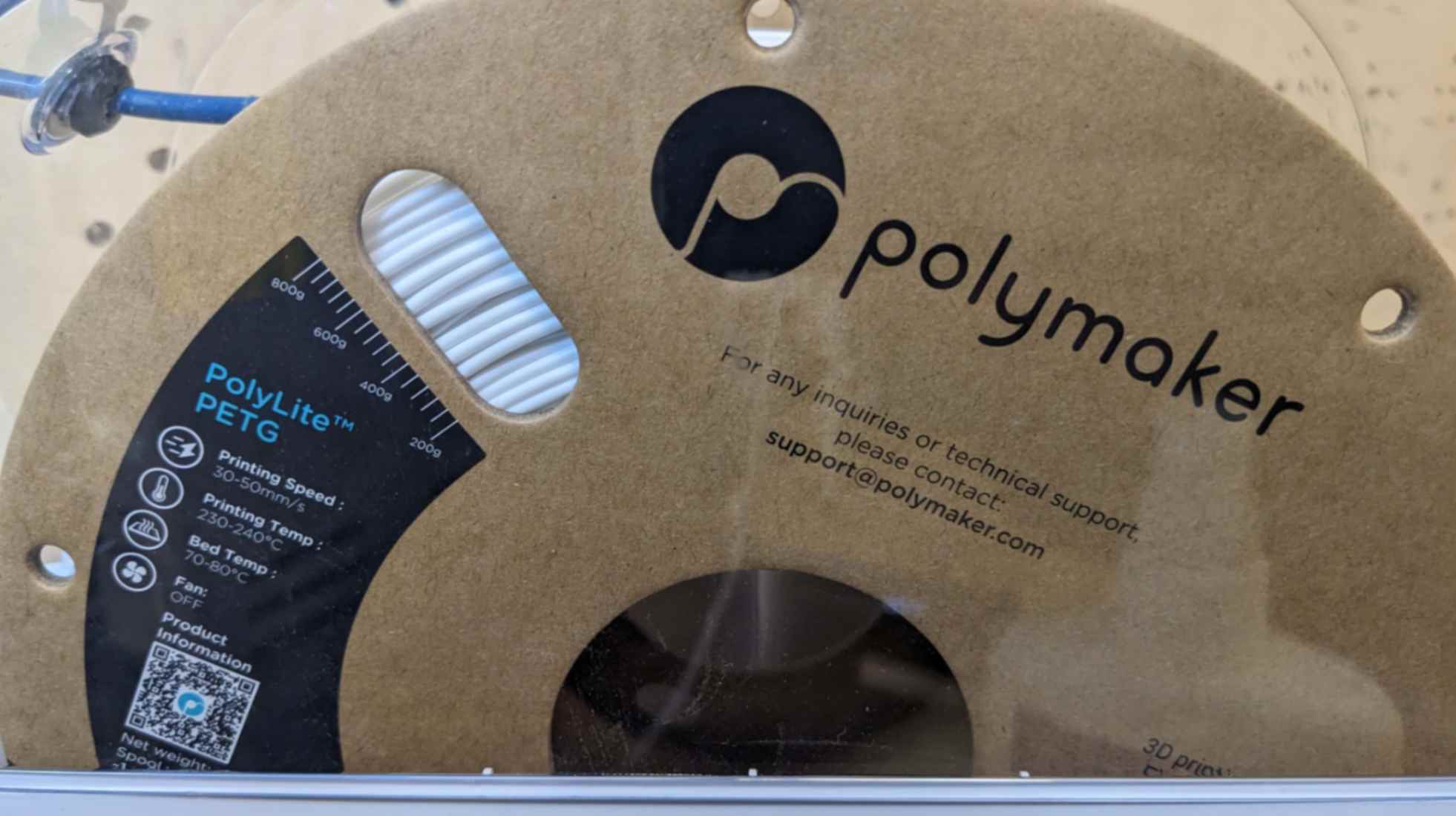
After discussing about the 1st and 2nd trials with my tutor, I was advised to print the 3rd trial with PETG because it is also strong and durable for movements. This time I made the model with small connections between the triangle hinge and other components as I learned from 2nd trial.
To print with PETG, I changed the Material temperature to 235, and the Print speed to 30mm/s to make it suitable for the material property of PETG. Also, I decided to print overnight when no one is in the room since PETG produce some toxic fuel when it is heated for printing
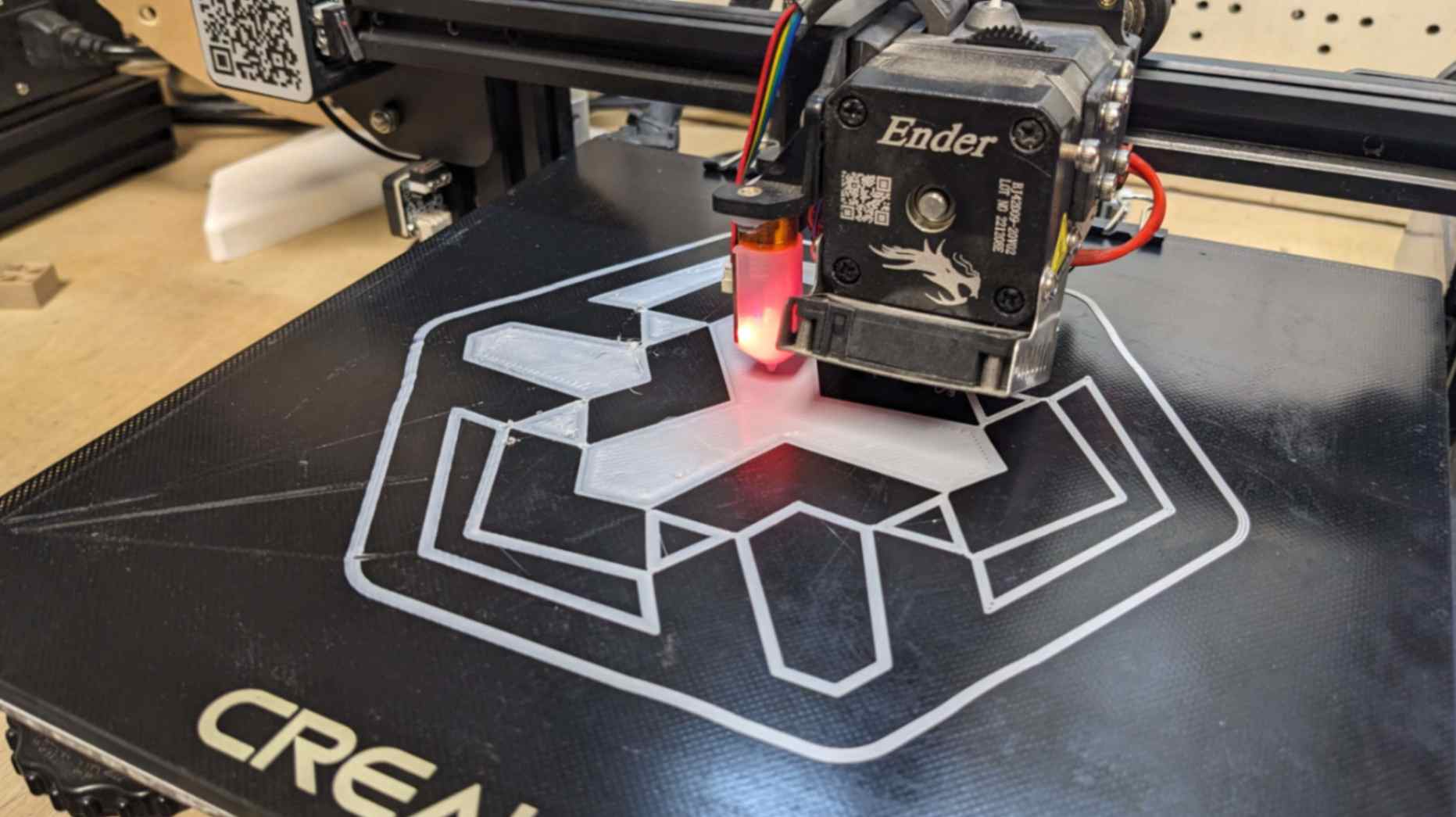
Result
As a result, the print came out nicely and it was also easy to take it out from the bed. However, the shape was not squishing. I think this was cause either the connecting parts were not giving enough space for the triangle to move or the strength of the PETG was not suitable for this type of movement. I tried to squish the shape with more force and the parts ended up breaking.
Files03_Compliant Mechanism_PRINT.stl
Again, I give full credit to my tutor Santi for successfully breaking my precious shape.
Overall Reflection
After doing several experiments, I learned that I need to be a little bit more careful in understanding the material property and modelling the shape with a consideration of the material. Also, I thought the shape was simple and good for testing but now that I think about it, it is not that simple because all the parts are connected which makes at least three compliant mechanisms work at the same time. For future experiments, I should choose a much simpler compliant mechanism with a single moving part. Also, I am very curious to see how the compliant mechanism works when it is printed with Flexible material.
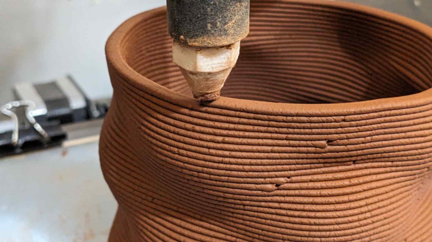
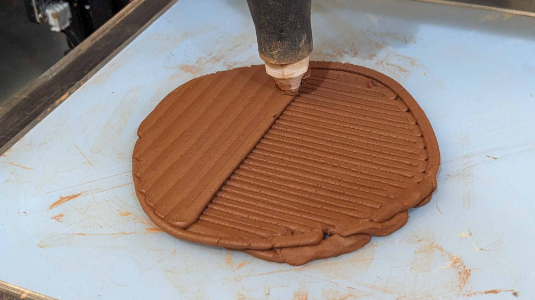
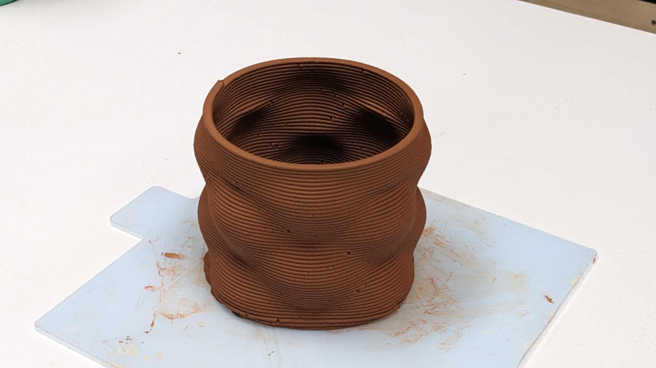
Paste Printing
In class, we were introduced to Paste Printing using clay. I was very curious about the printing technique since IAAC is well known for the 3d printed architectural structure using paste printing. I decided to try printing with it.
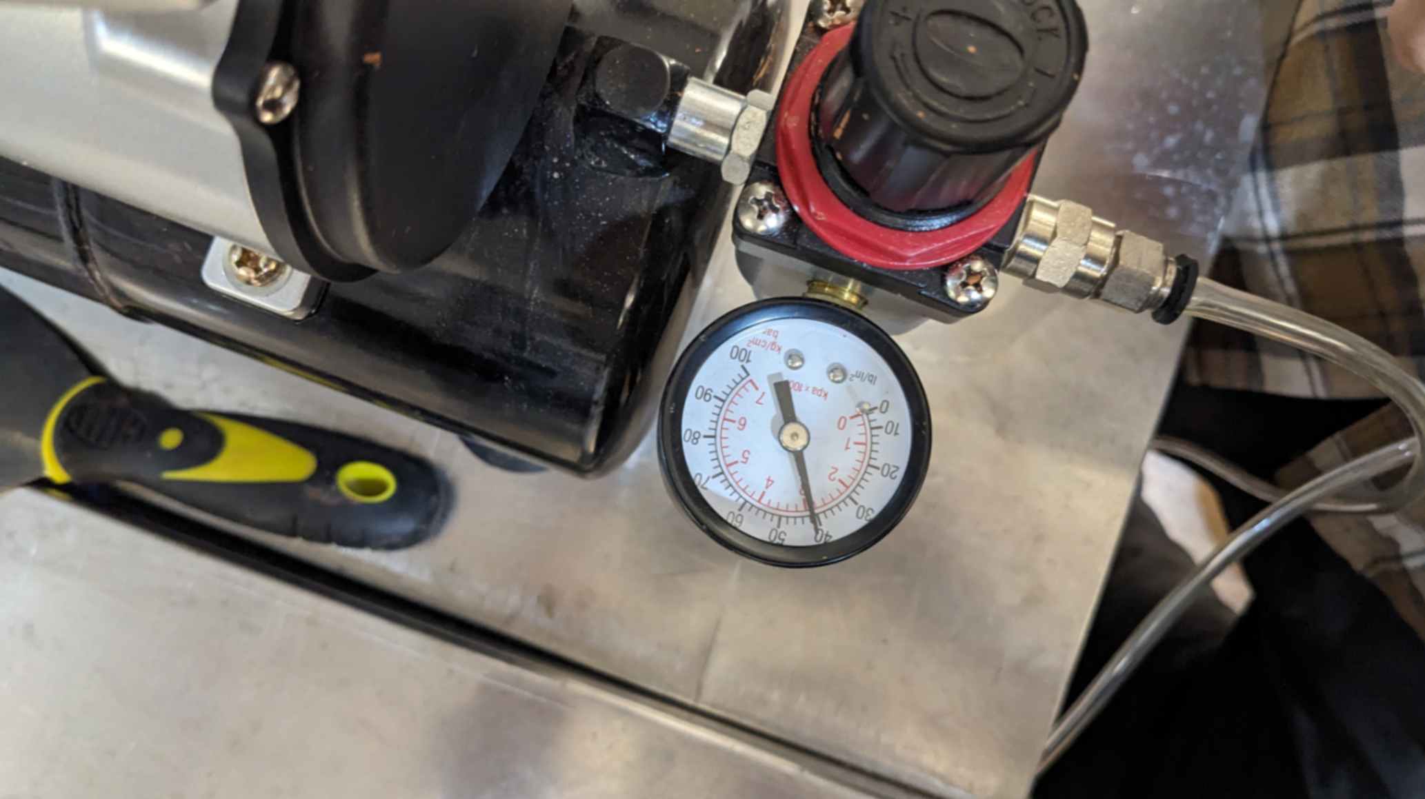
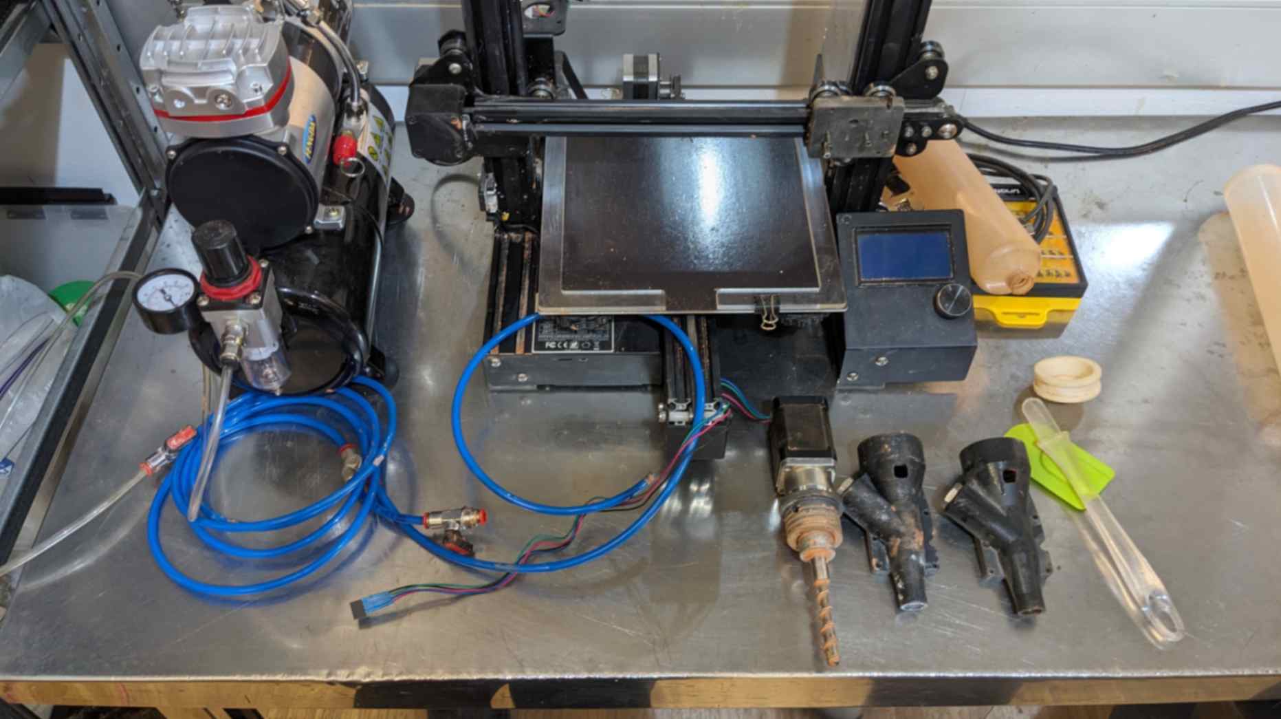
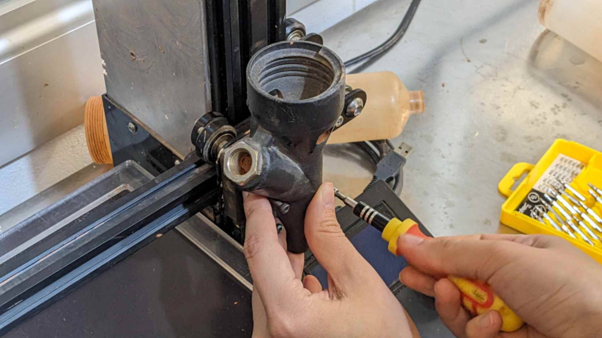
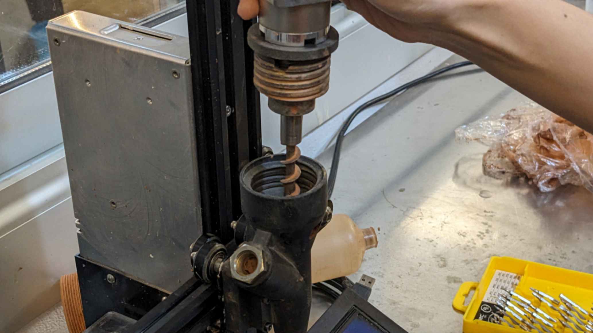
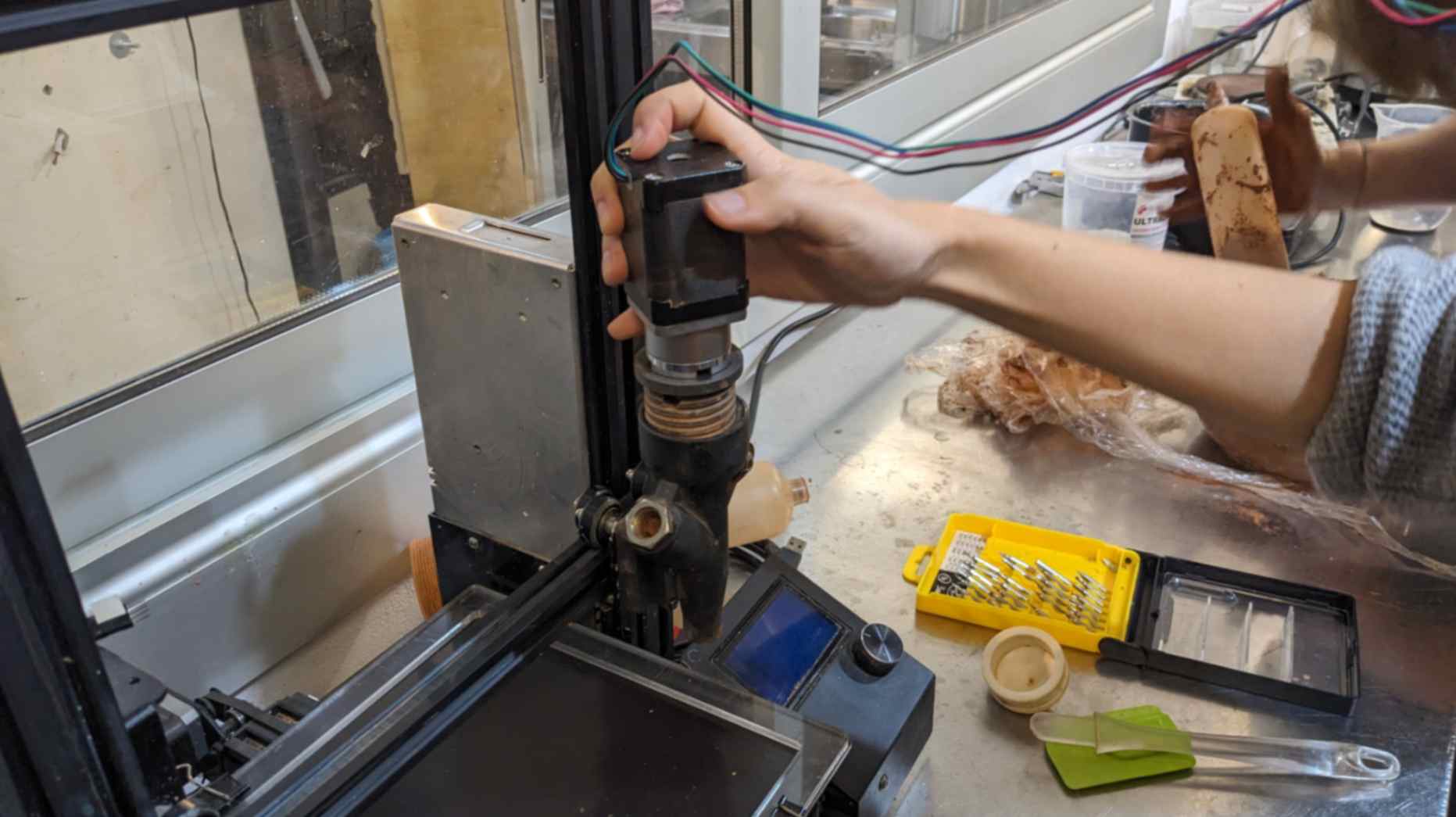
As a piece of general information, IAAC developed this paste printing machine by hacking the Ender 3d printing machine. They changed a printing head to a special head which has a custom nozzle, a drill to push out clay, a bottle to stock clay, and an air compressor pushing the clay to the nozzle. They also have a Grasshopper plugin specially for this paste printing called MAMBA which can be installed for Food for Rhino. MAMBA allows you to set up the printing setting and create G-CODE which you need for the machine to print.
Modelling
I decided to model a coffee cup for the paste printing using Grasshopper. To start I used a book named ADVANCED 3D PRINTING with Grasshopper Clay and FDM by Diego Gracia Curevas and Gianluca Pugliese. This book was recommended by one of my classmates and my tutor.

Loft & Spiral Path
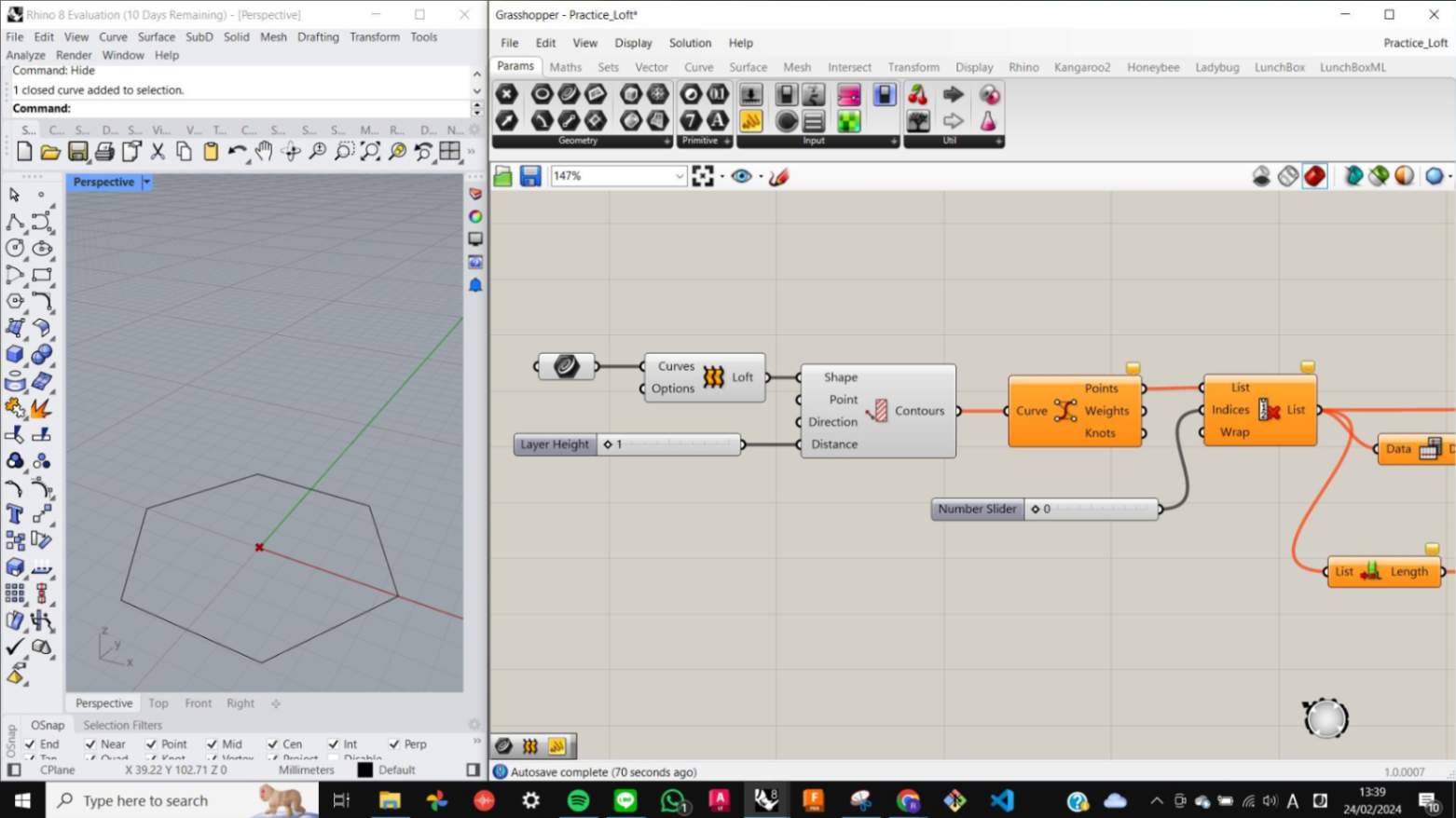
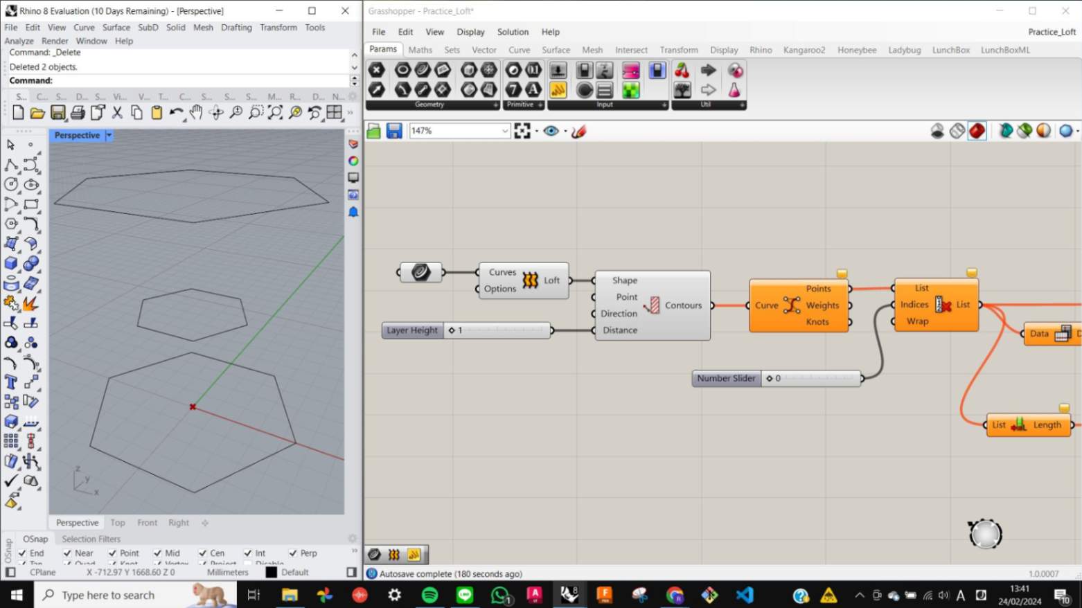
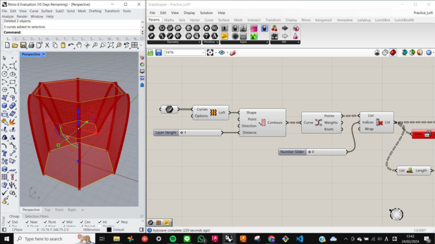
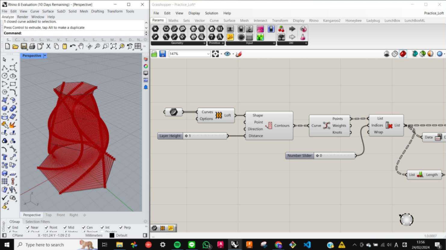
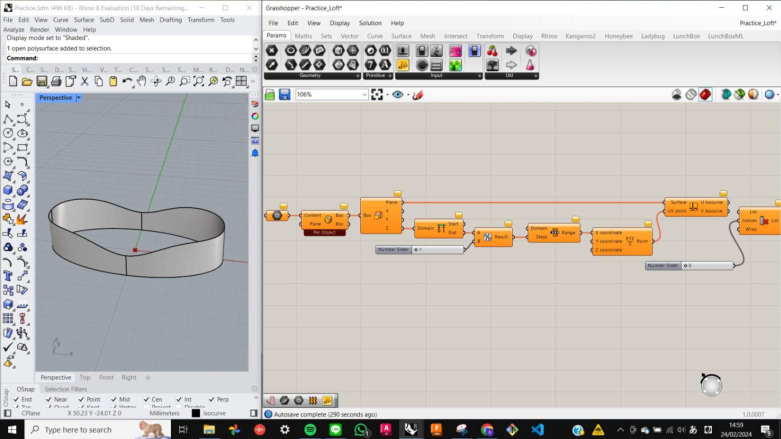
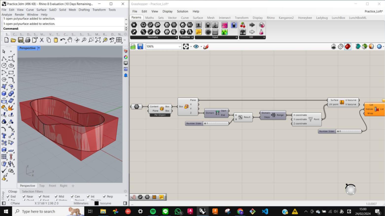
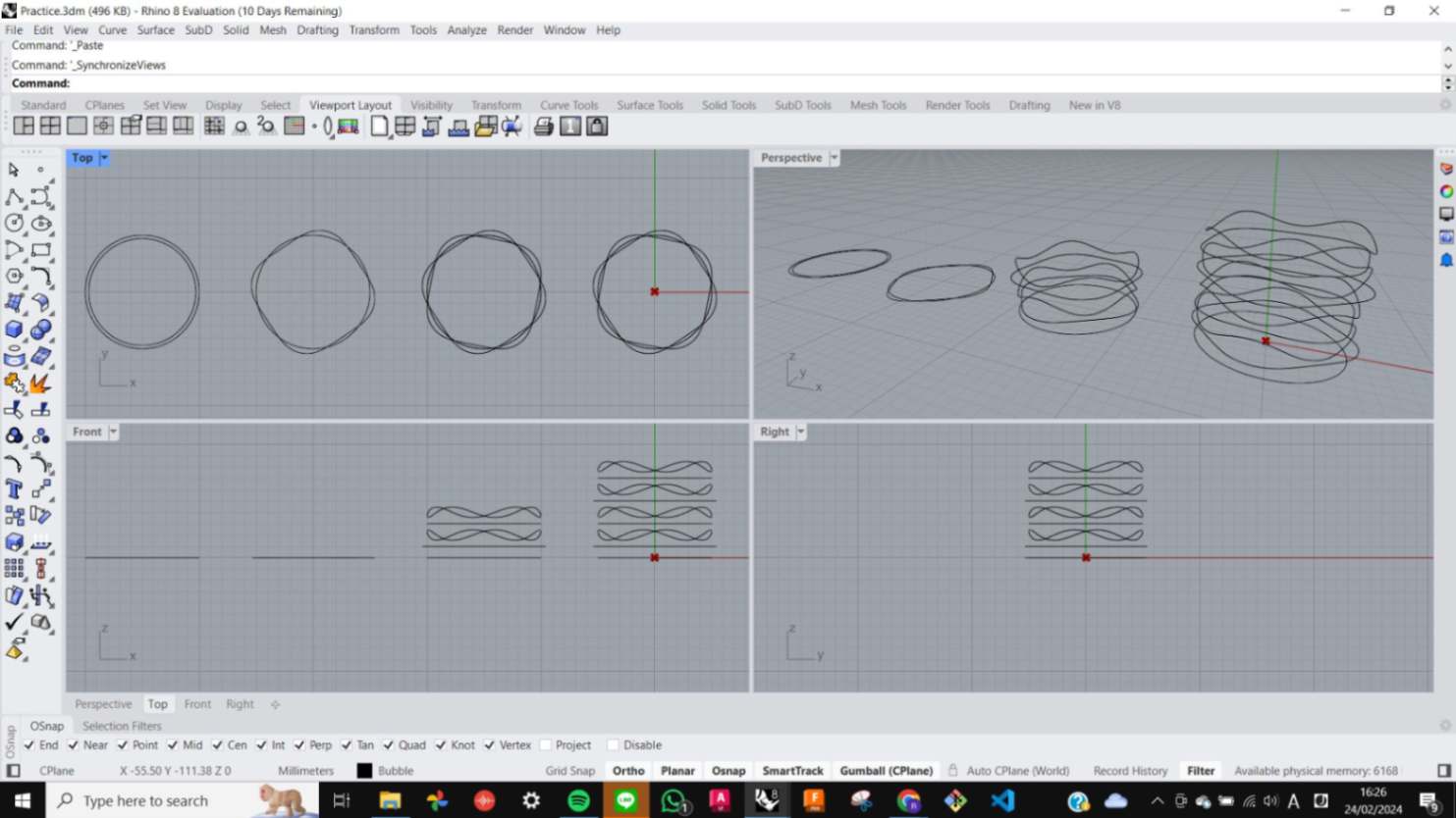
For making the model I started with a Loft section in the book. First, I replicated the nodes which were shown on the page and started deconstructing nodes one by one to get a general understanding of what they are doing and why they are included in the process of making the shape.
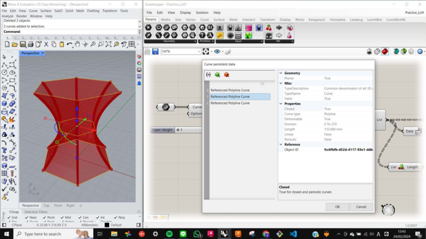
One of the crucial things that I realized by doing this practice is that when you choose curves for Geometry nodes, the order you choose curves matters. This is also changed later by adjusting the order in Curve persistent data windows. Also once the curves are connected to the geometry node, I can tweak the original curves in Rhino to make different loft shapes.
Files
Loft_Spiral_Isocurve_01.gh
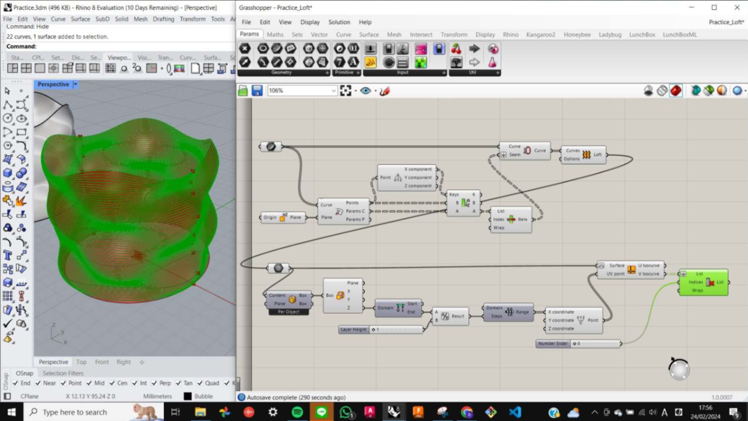
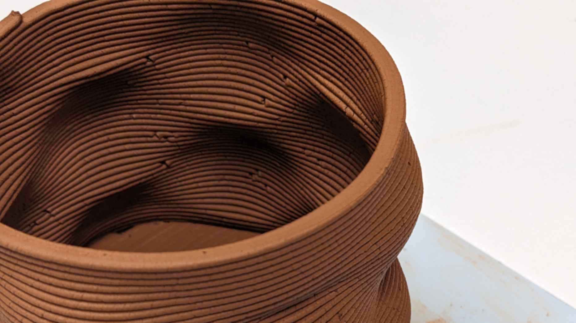
Isocurves
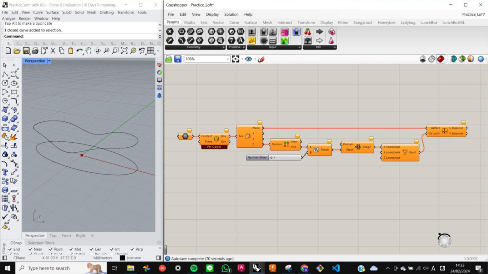
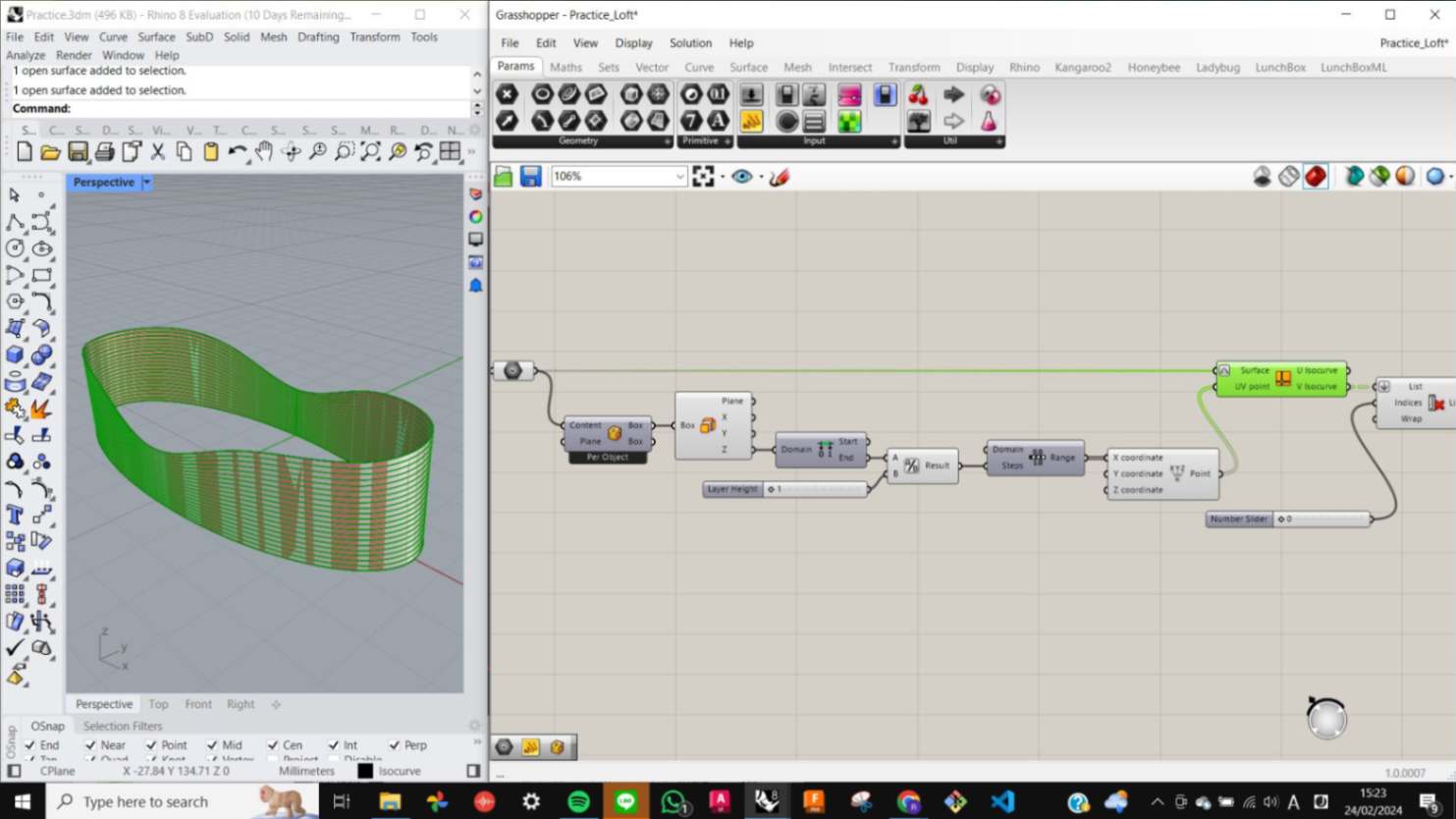
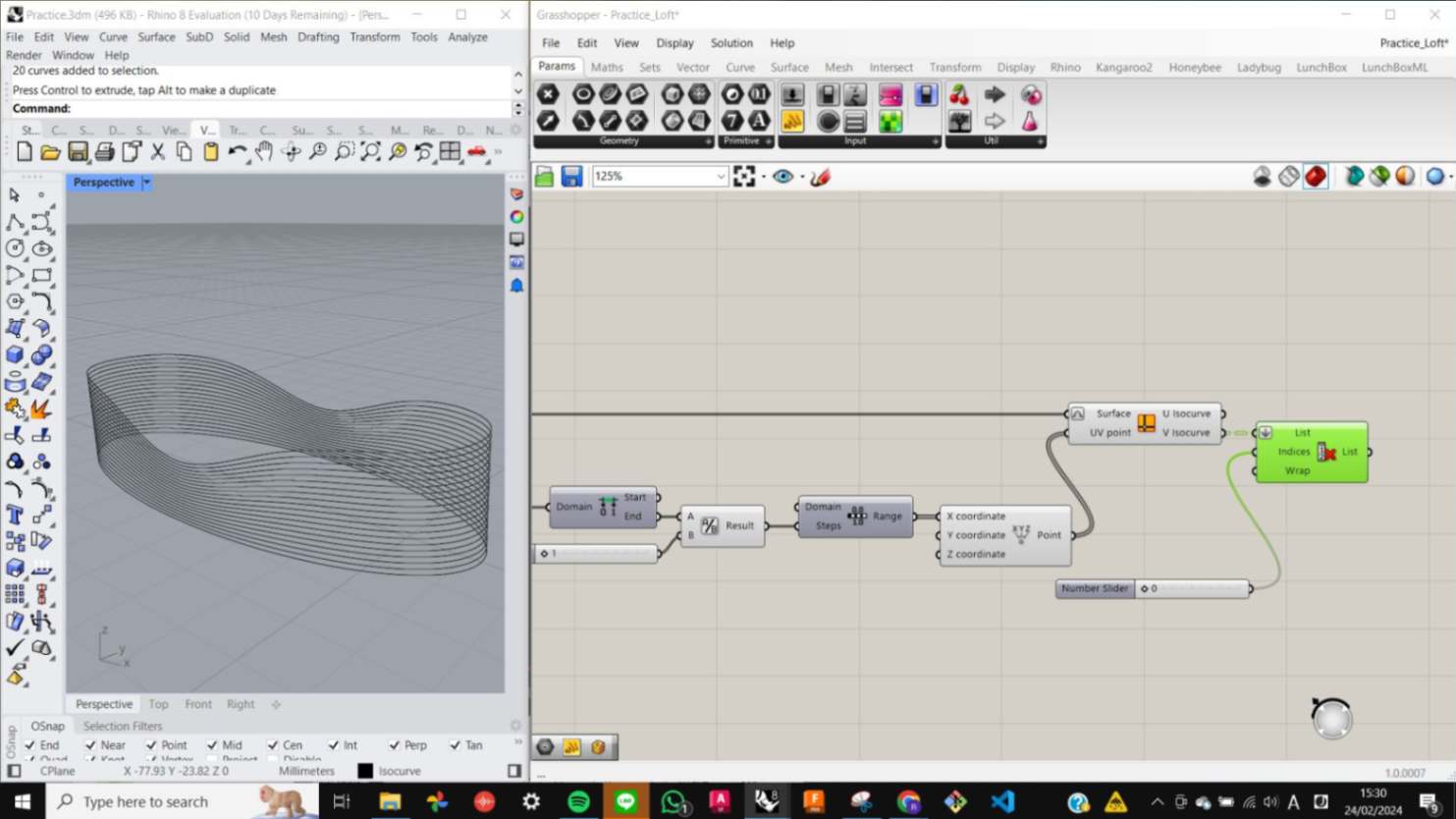
Making Isocurves is useful when I want my model to be sliced unequally and follow the Z-axis value of the model. Having this isocurve included in the printing path will result in a unique surface texture on a printed surface.
Same as before, I replicated the nodes which were shown on the page and started deconstructing nodes one by one to get a general understanding of what they are doing and why they are included in the process of making the isocurves.
Files
Loft_Spiral_Isocurve_01(1).gh
Loft_Spiral_Isocurve_02.gh
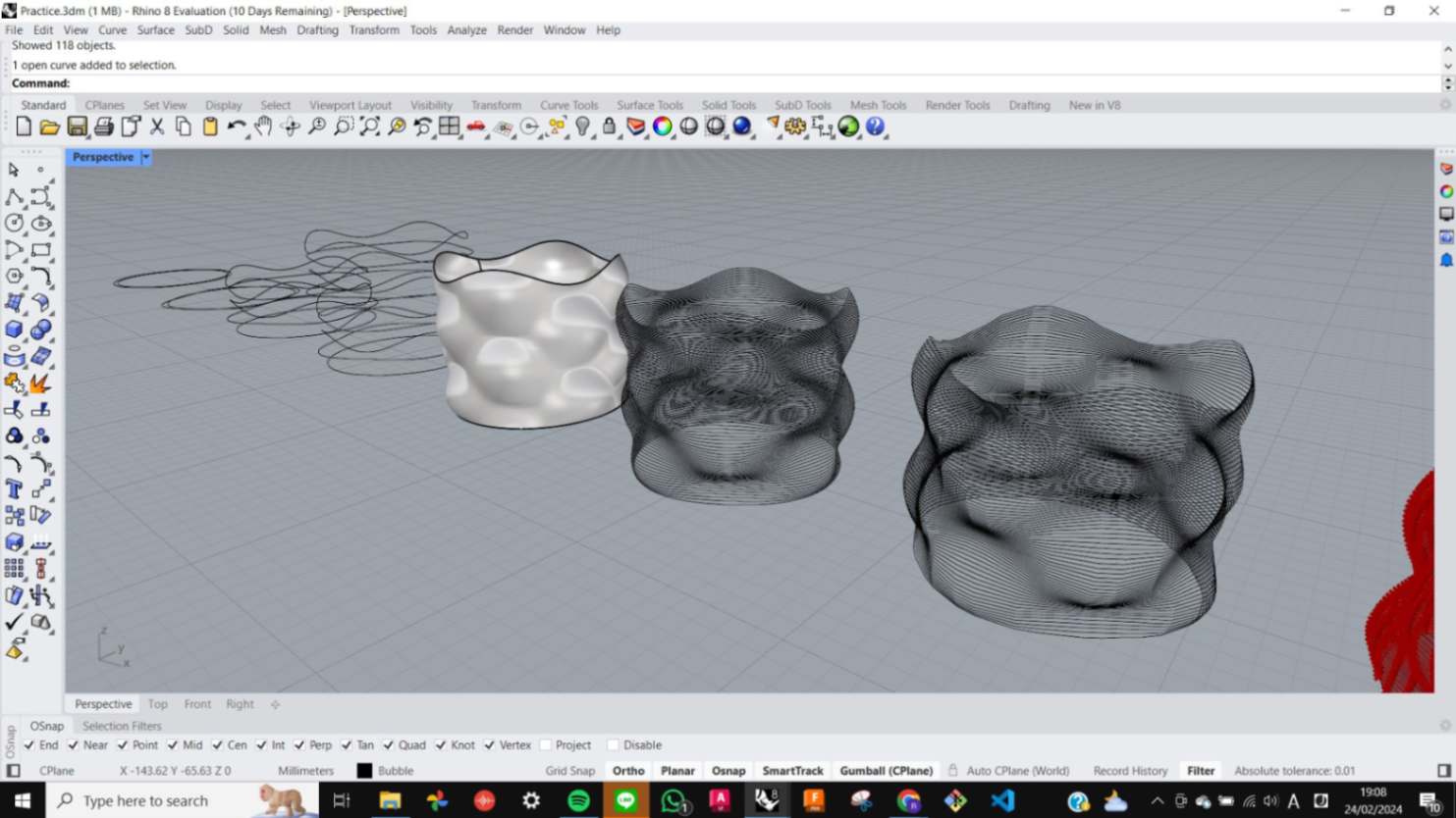
Bubble shape
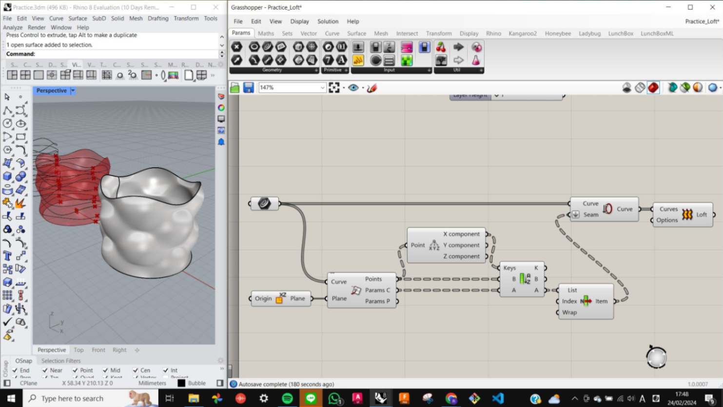
I liked the example that was in the book. I named it Bubble shape and I decided to make the model of it. In this process, I also followed instructions in the book. Making the surface of the Bubbke shape was much simpler than I thought. It is created with a sandwich of two types of a curve, one is a circular curve distorted by pulling horizontally and another is the same but vertically.
After making the shape, I used the equation I made for previous exercises to convert the model into a spiral curved printing path. It was a fairly easy process since all I needed to do was to connect three different equations by plugging them into each other, however, I realised that connecting from which nodes in the equation to nodes is very crucial because it will not work if the equations are not connected with right nodes.
Files
01_BubbleCup_PRINT.3dm
Mamba
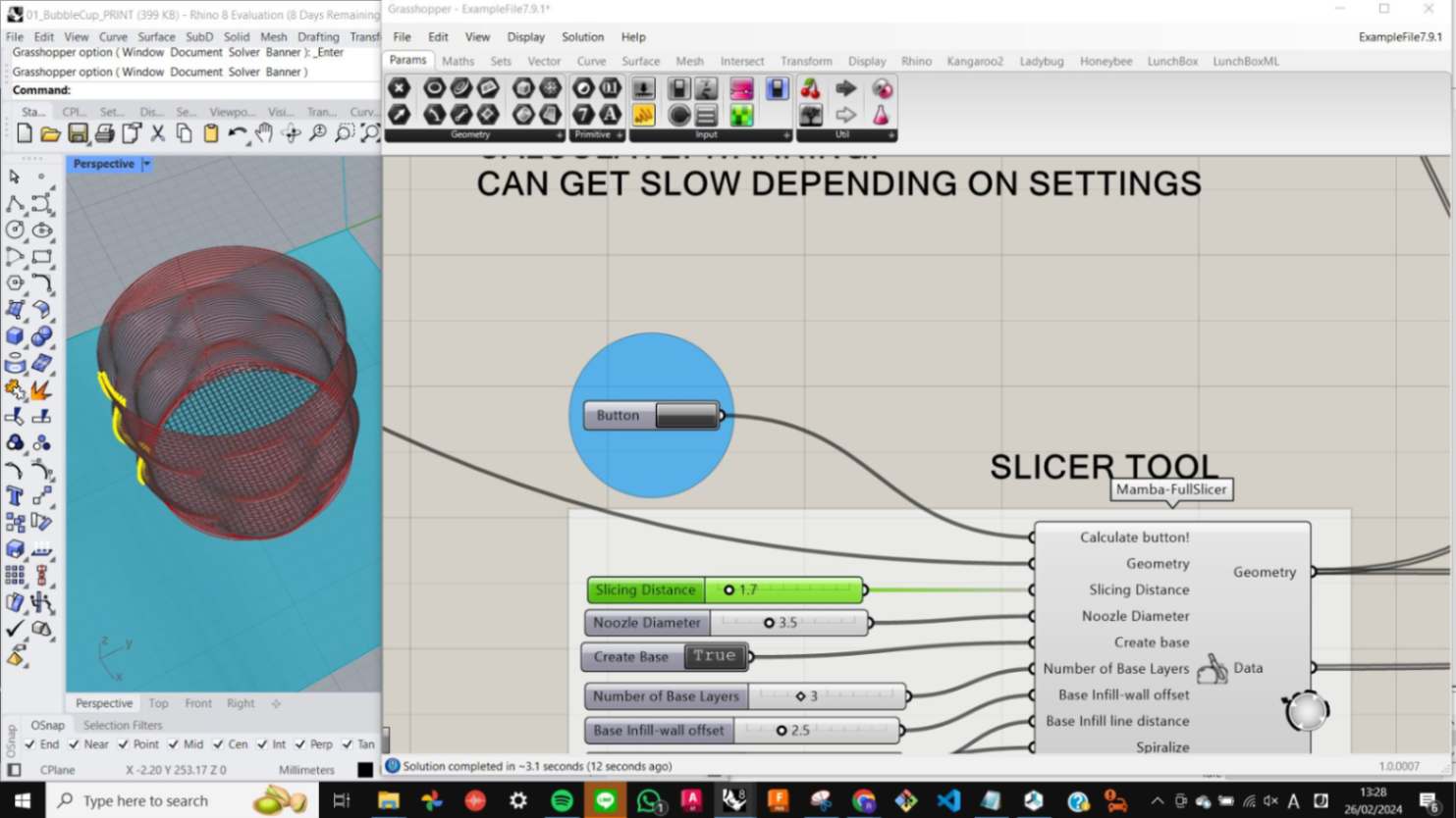
After making the model for paste printing, I needed to go through a phase of generating GCode to communicate with the paste printing machine to print my model. To do that, IAAC develops MAMBA which is a grasshopper plug-in for Rhino. To start, I went to the FoodforRhino website and downloaded Mamba V7.9.1 and Mamba Example File 7.9.1. After the hat, I open a new project in Rhino and Grasshopper. In Grasshopper, I went File tab and opened the Special Folder, then dragged and dropped all the MAMBA V7.9.1 files into the special folder, then restarted Rhino and Grasshopper to finish installing MAMBA.
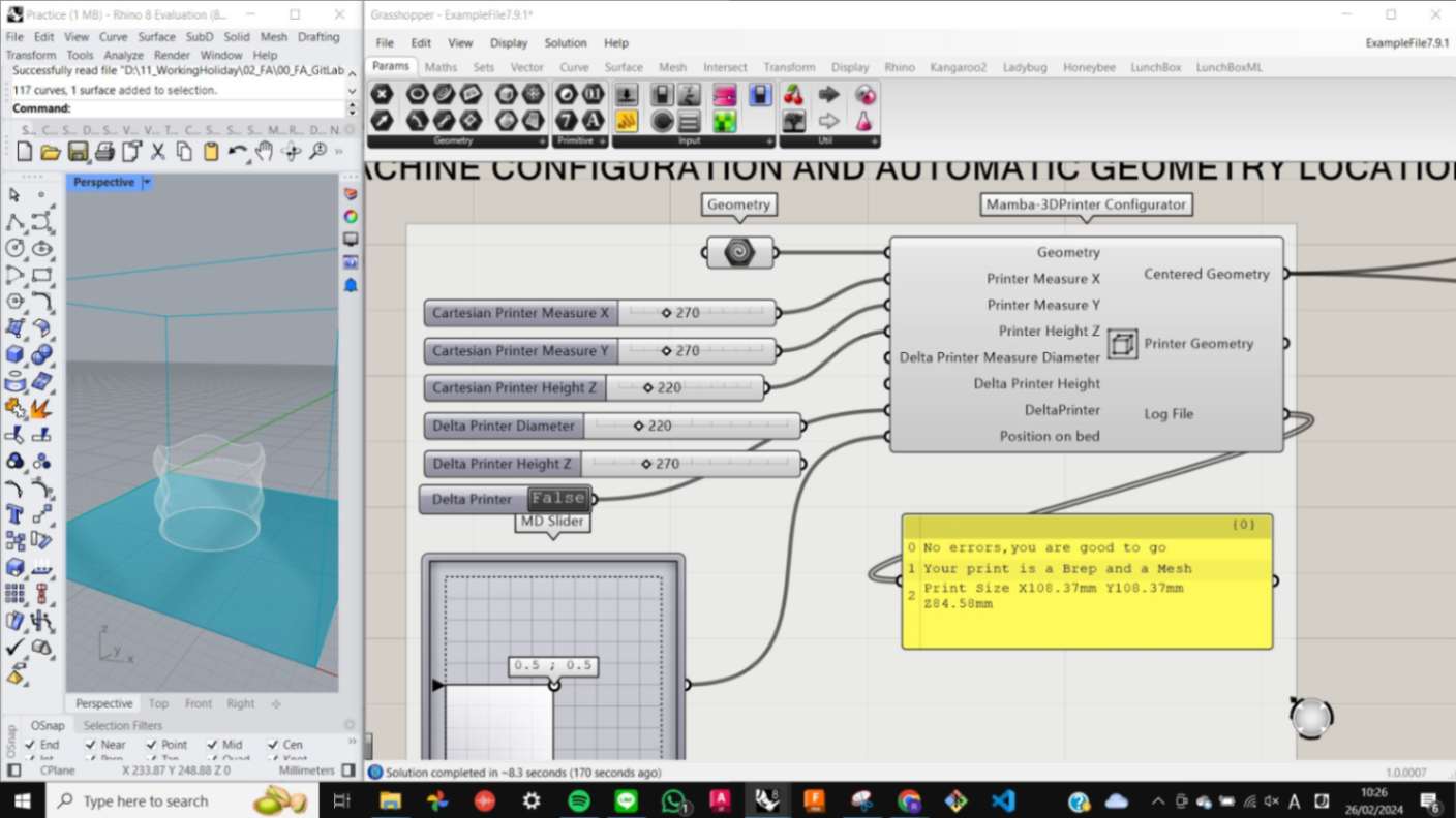
After Installing I opened the Example file and imported my model to the Grasshopper equation using Geometry nodes. There was a problem. When I pressed the calculating button to generate the printing path, the printing path became spaghetti on the top part of my model. This was because of the confusion between my curved shape and parallel silencing setup. The ideal way to fix this is to use is curved path that I generated before as a printing path, although I was not able to figure out how to do it. So I decided to make the top part of my model flat for the machine to be able to parallel slice my model.
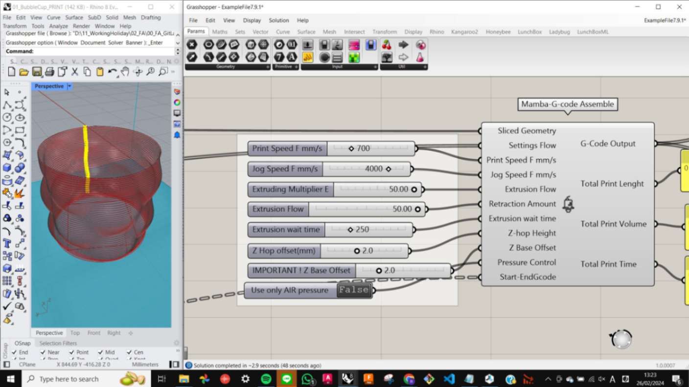
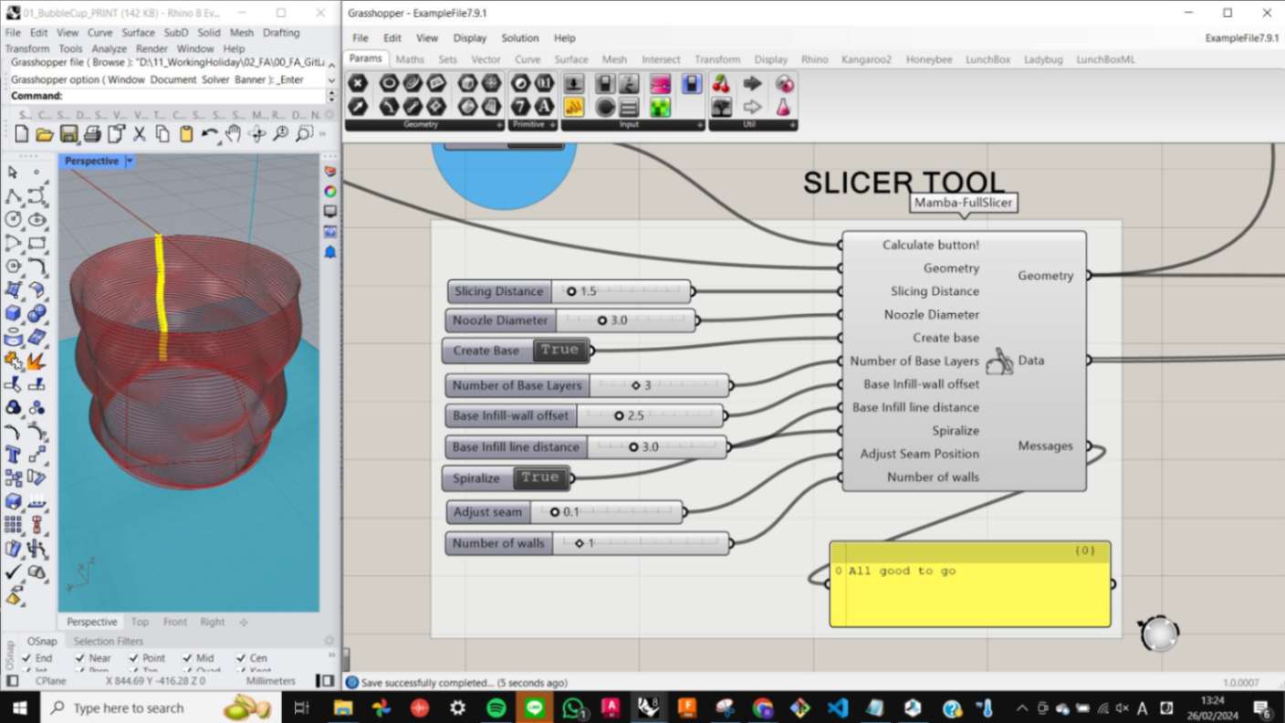
For the parameters in Machine Configuration and Slicing Tool, I was advised to adjust them as shown in the image. Those parameters are decided by previous trials done by my tutor and my classmate Andrea. I give full credit to them for their effort in finding the right value through many trials and errors.
After setting up the parameters for the printing, I needed to export the file as GCode however, the function for navigating the exported file was not working for some reason. So I decided to simply copy the Gcode and paste it into Notepad by using the function Copy Data Only.
Files
mambav791.zip
examplefile791.zip
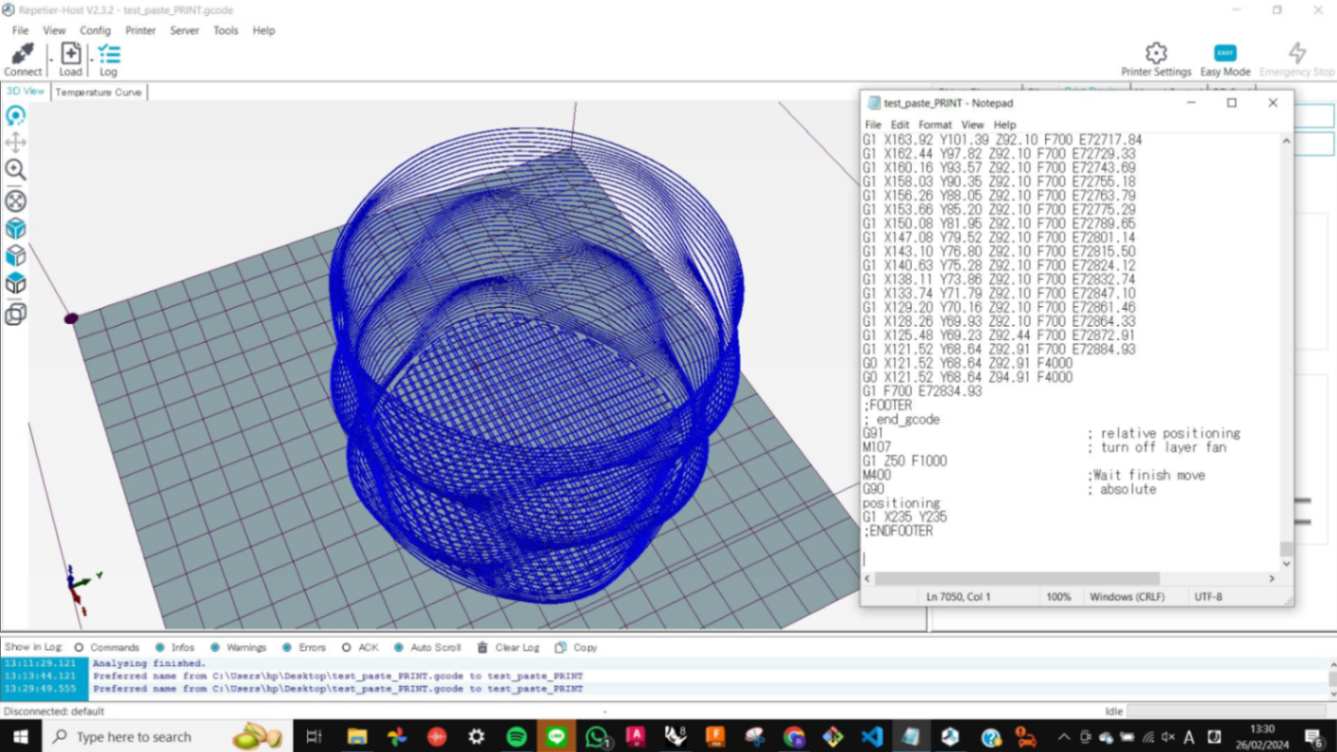
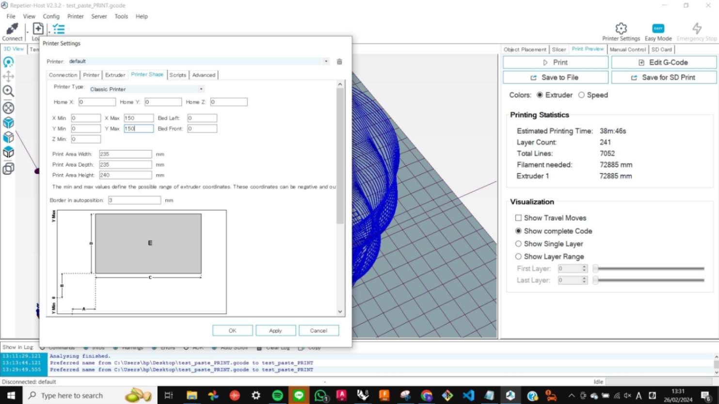
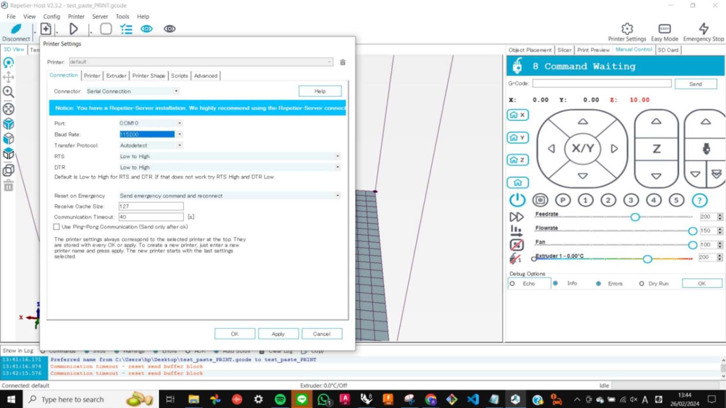
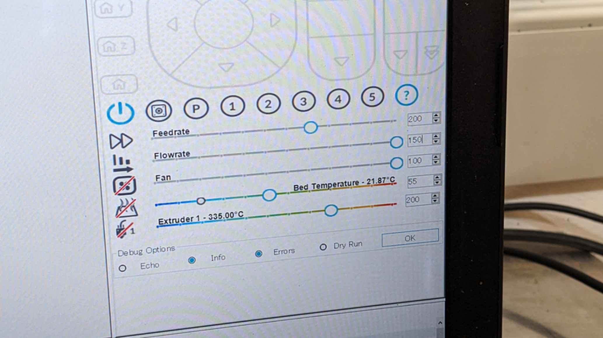
Repetier
Repetier is a software I used to communicate with the printer by GCode. I simply imported my GCode, connected the printer by USB cable, set the value for max XY, set values for XYZ for Print Area, set Feedrate and Flowrate, and finally the file was ready to print.
Files
01_BubbleCup_PRINT.gcode
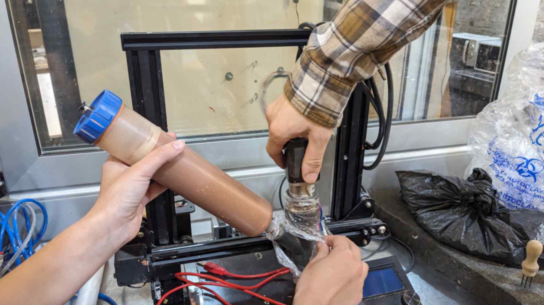
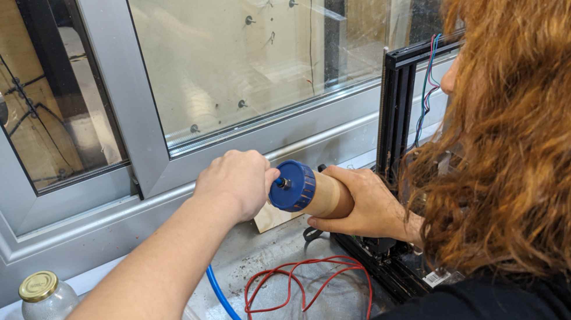
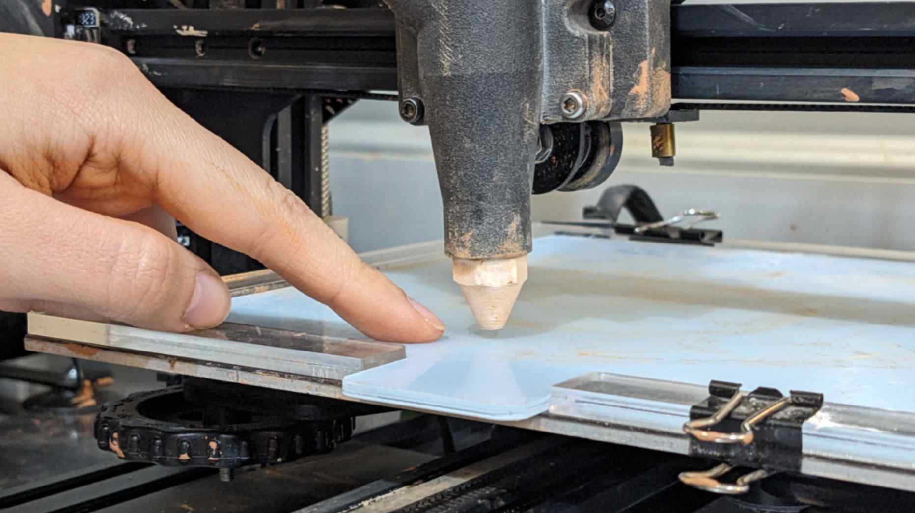
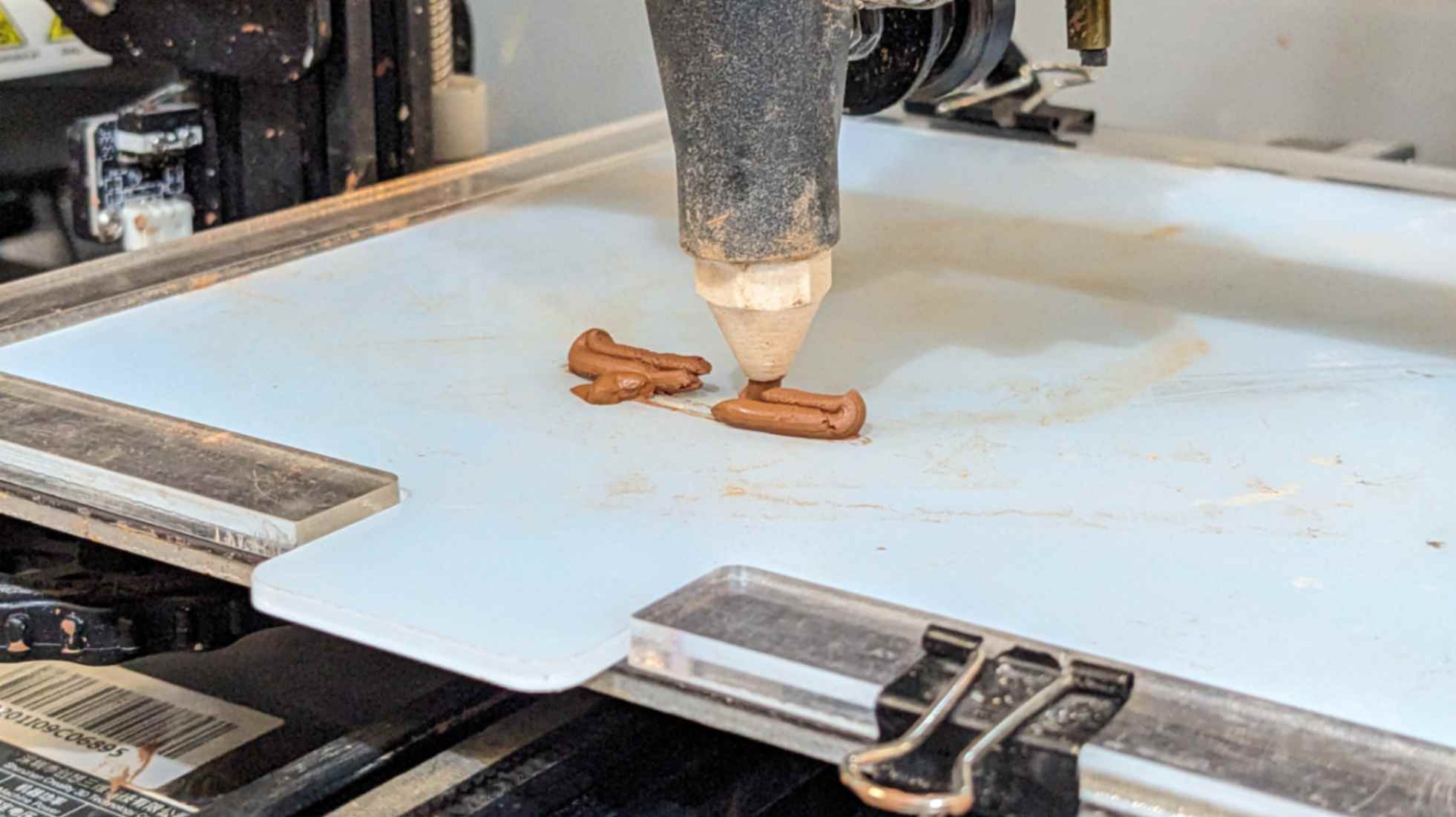
Machine Preparation
Before starting printing the model, the printer itself needs to be set up. I will explain how to set up a printer step by step below
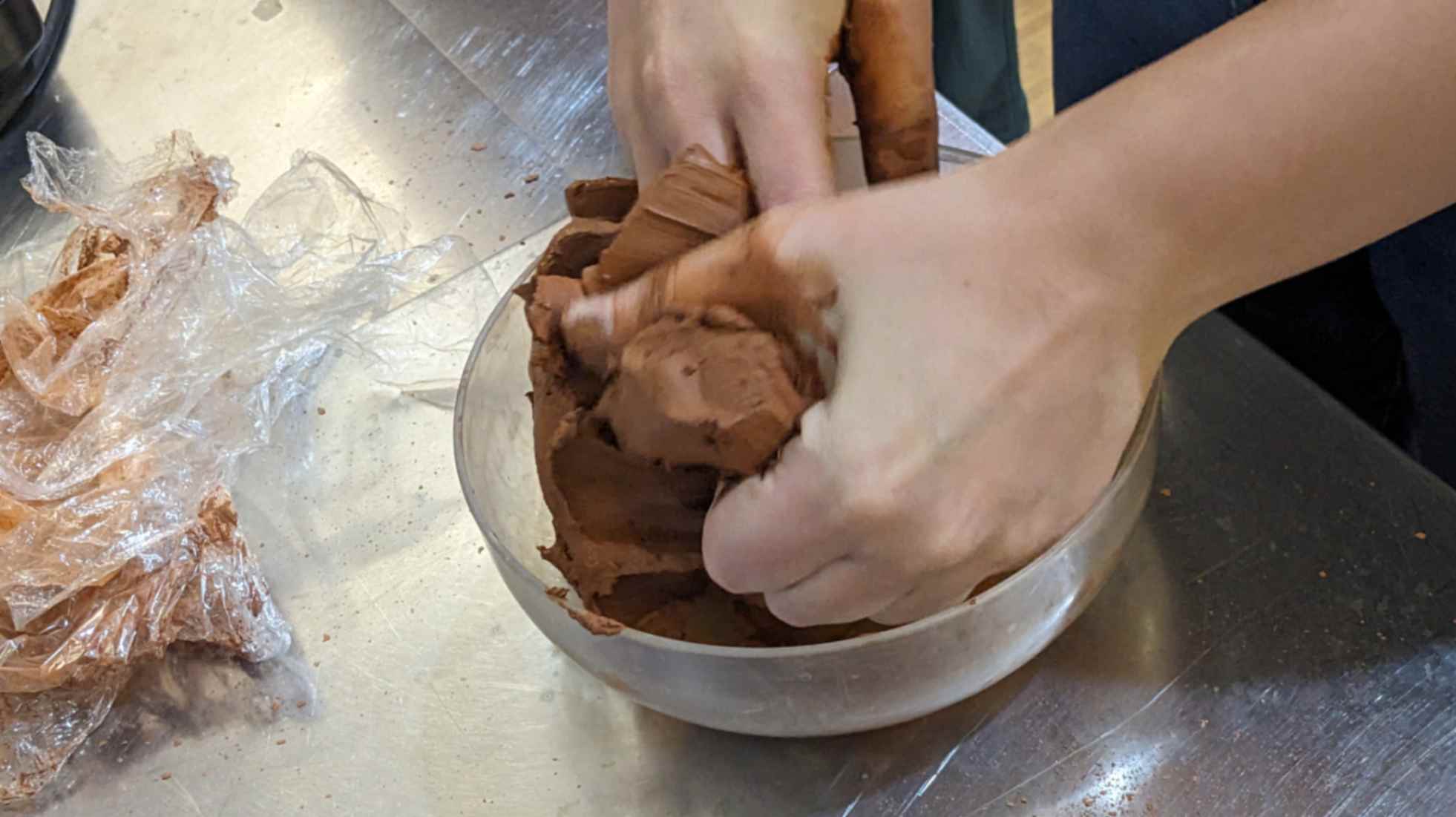
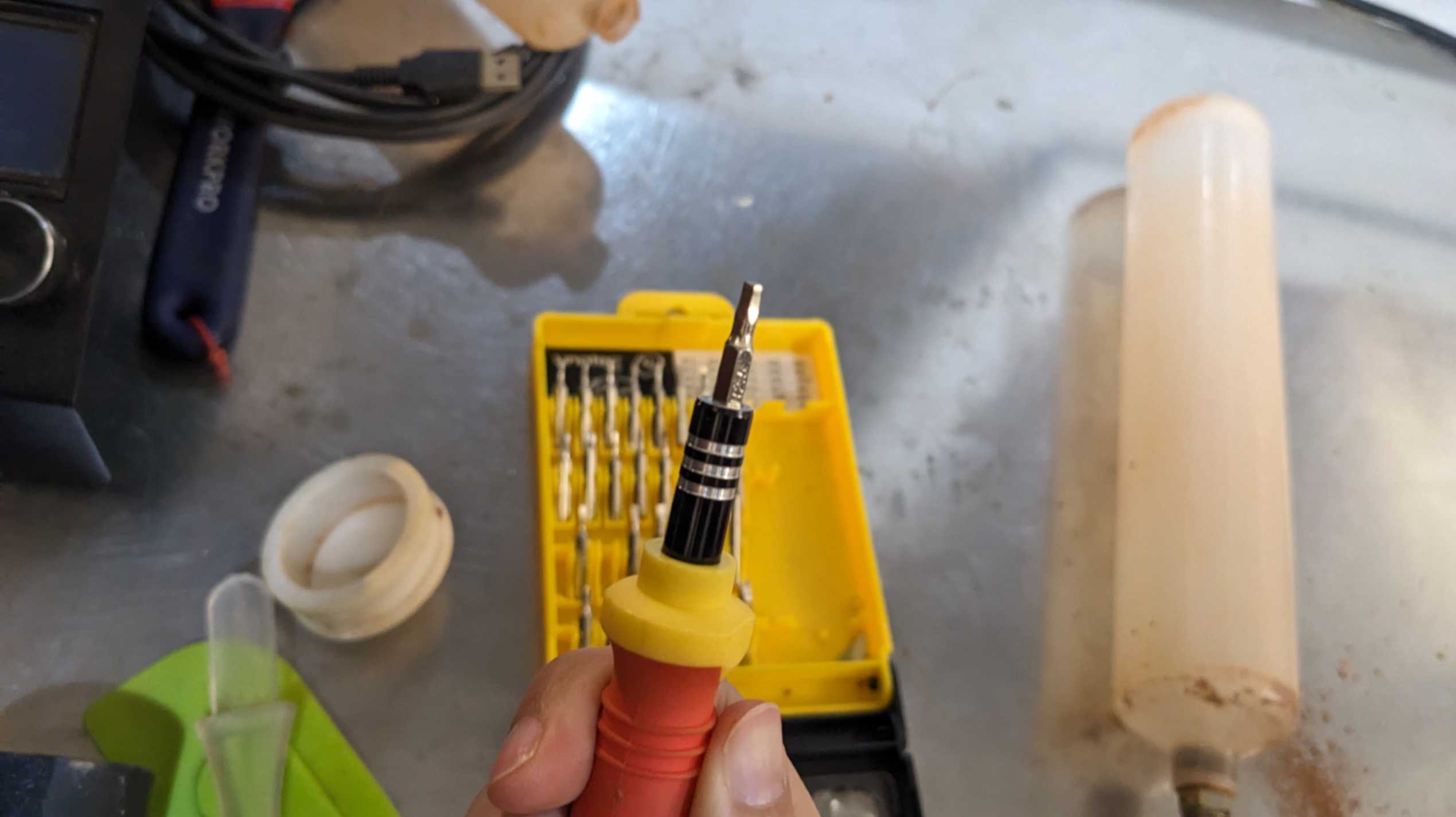
- Moisturise paste by mixing it by hand with a little bit of water ( I would like to find out this ratio for the next print)
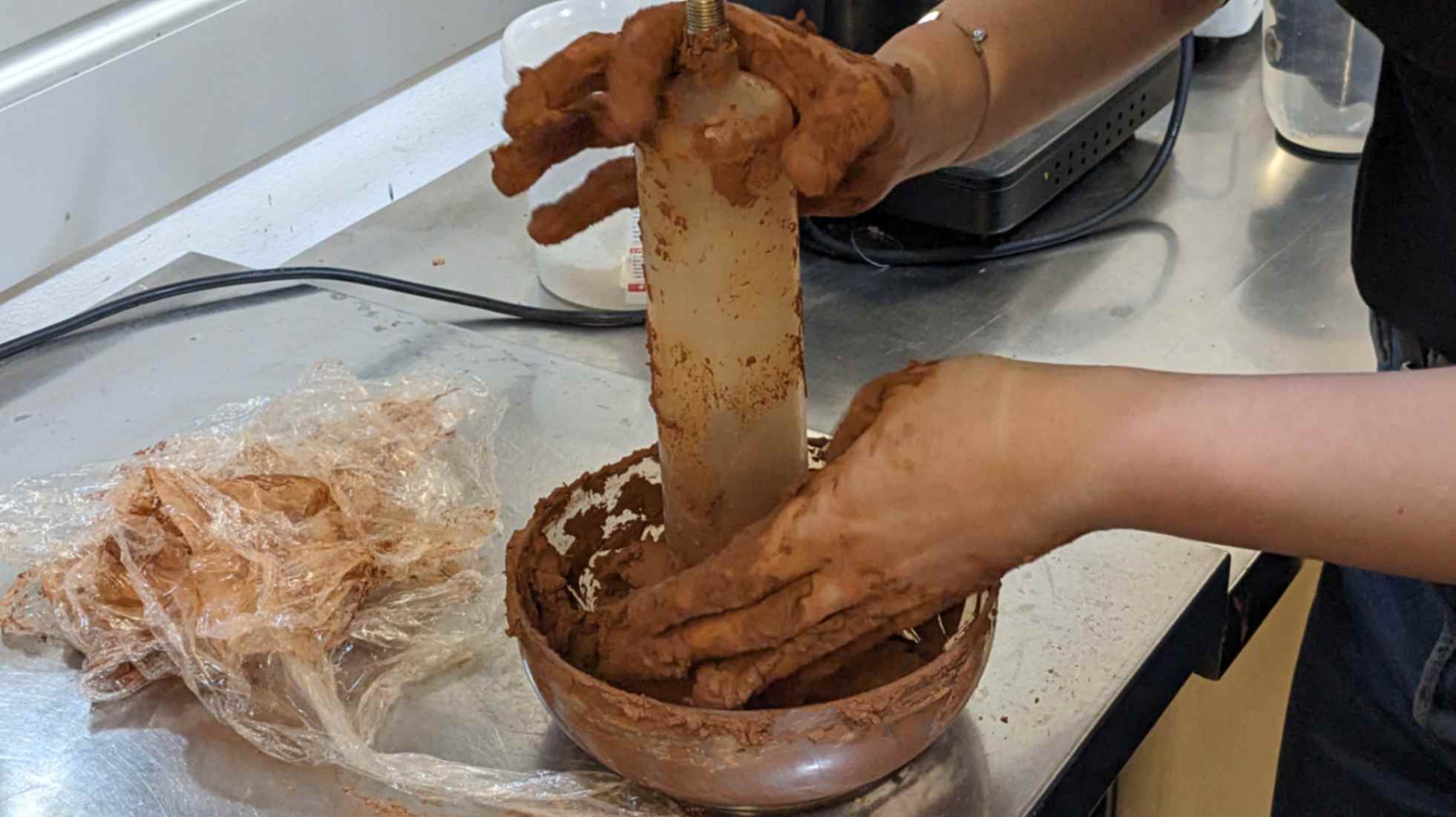
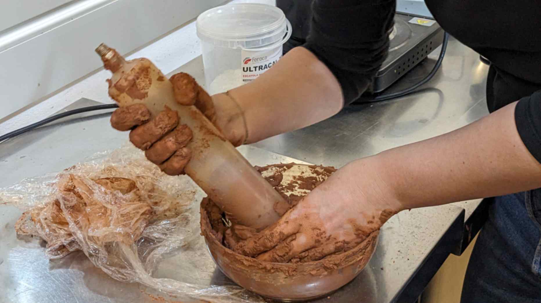
- Push in the pate to the bottle without any air bubble
- Set the printing head, the drill, the bottle, and nozzule
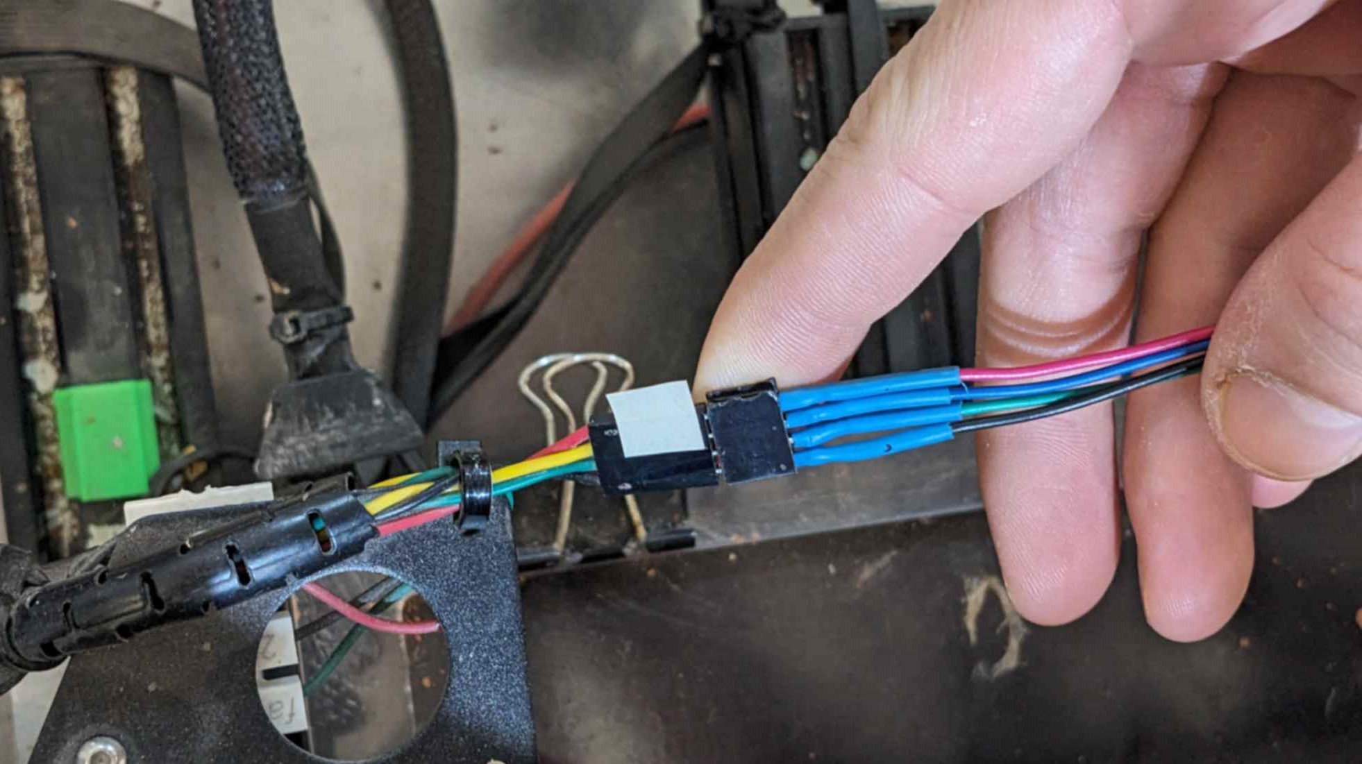
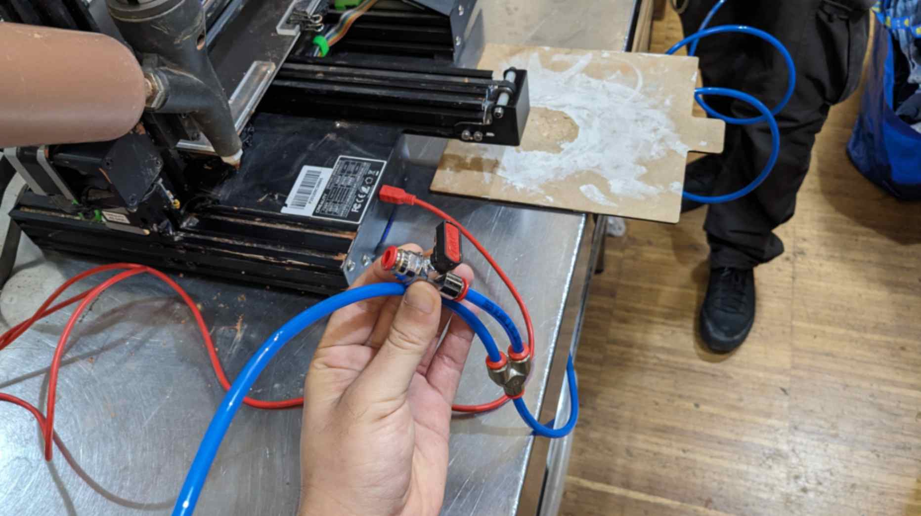
- Connect wire by aligning red wires
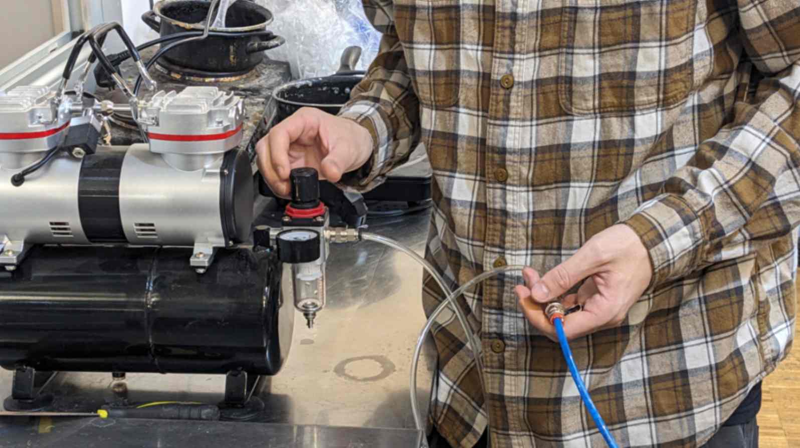
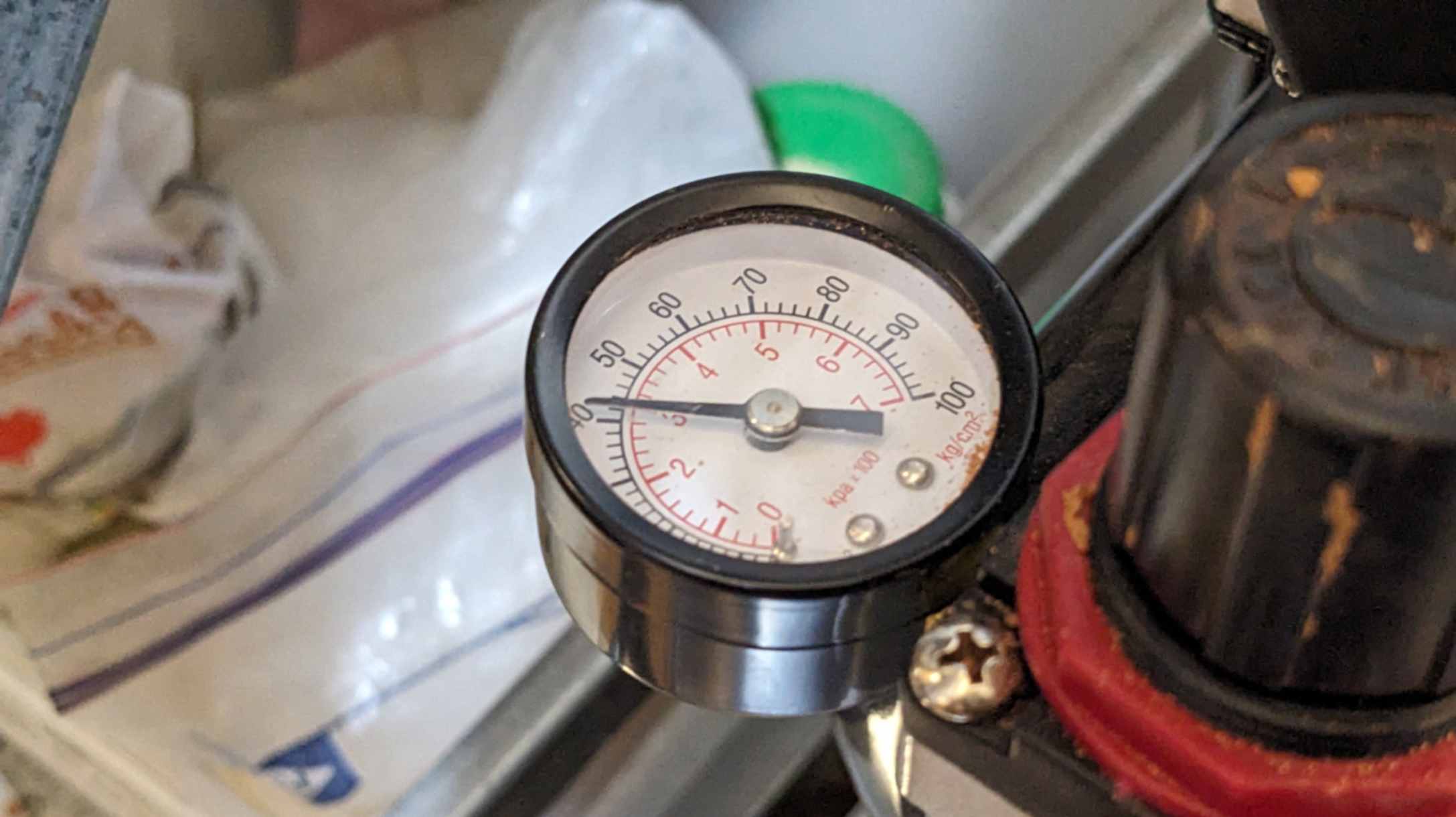
- Connect air compressor
- Turn on air compressor
- Adjust Flow, Z-axis origin, and Eztruder on the screen
- Turn on the air compressor, open the back tap and close the front tap
- Test print
- Adjust flowrate and feedrate in Repetier
- Print finally
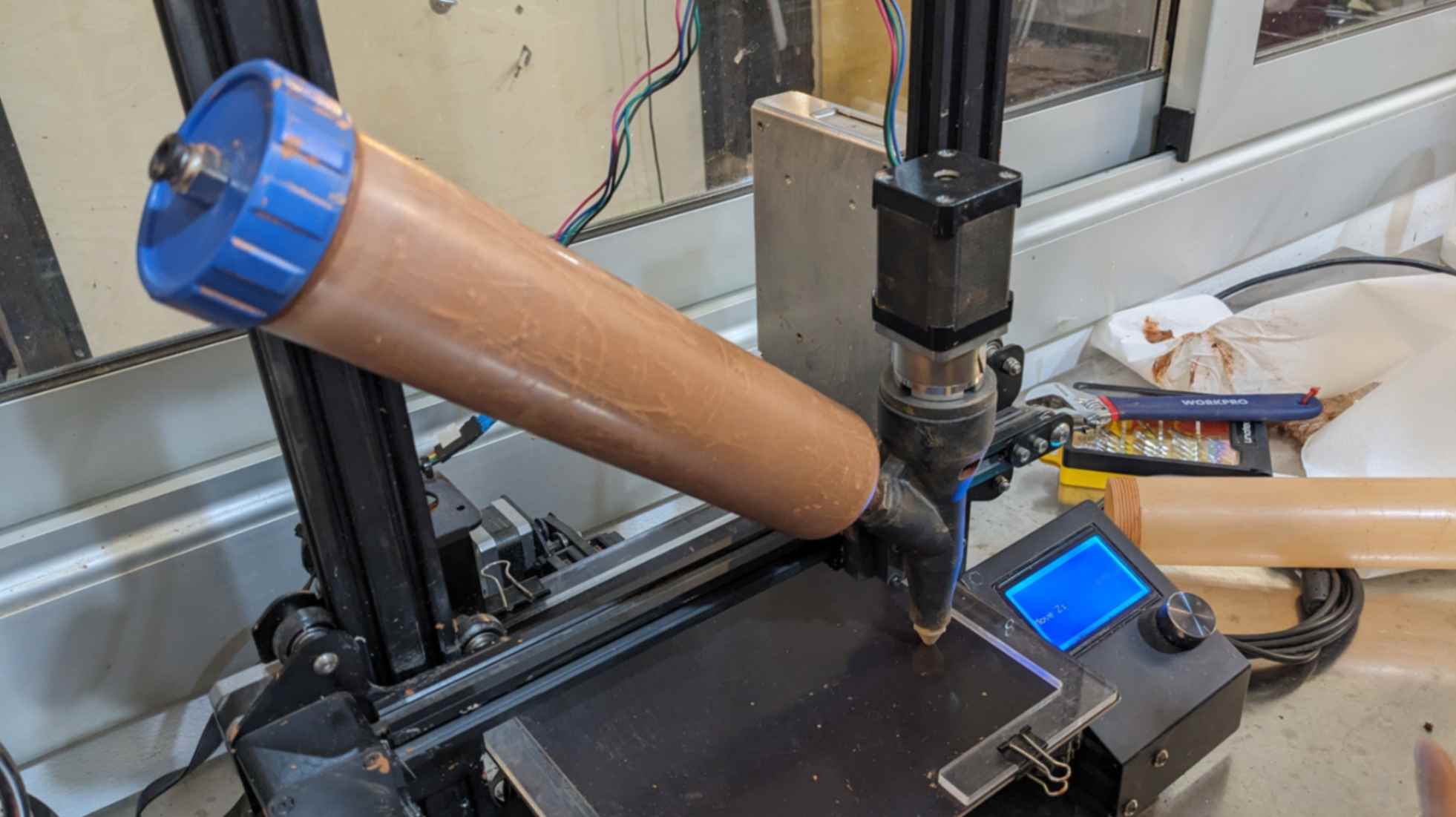
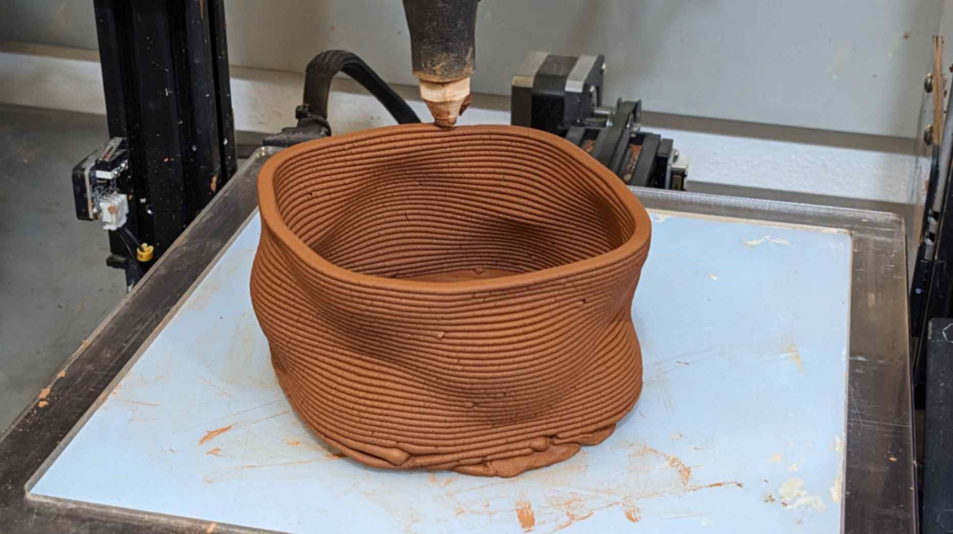
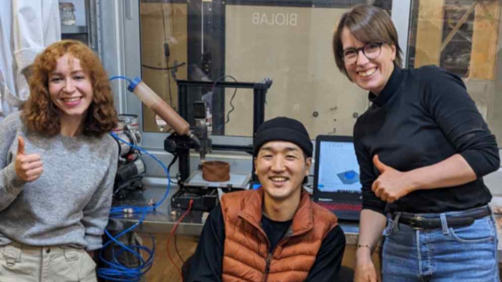
With the help of Lena, Tony and Andrea I was able to print my coffee cup successfully I appreciate their effort and kindness!!
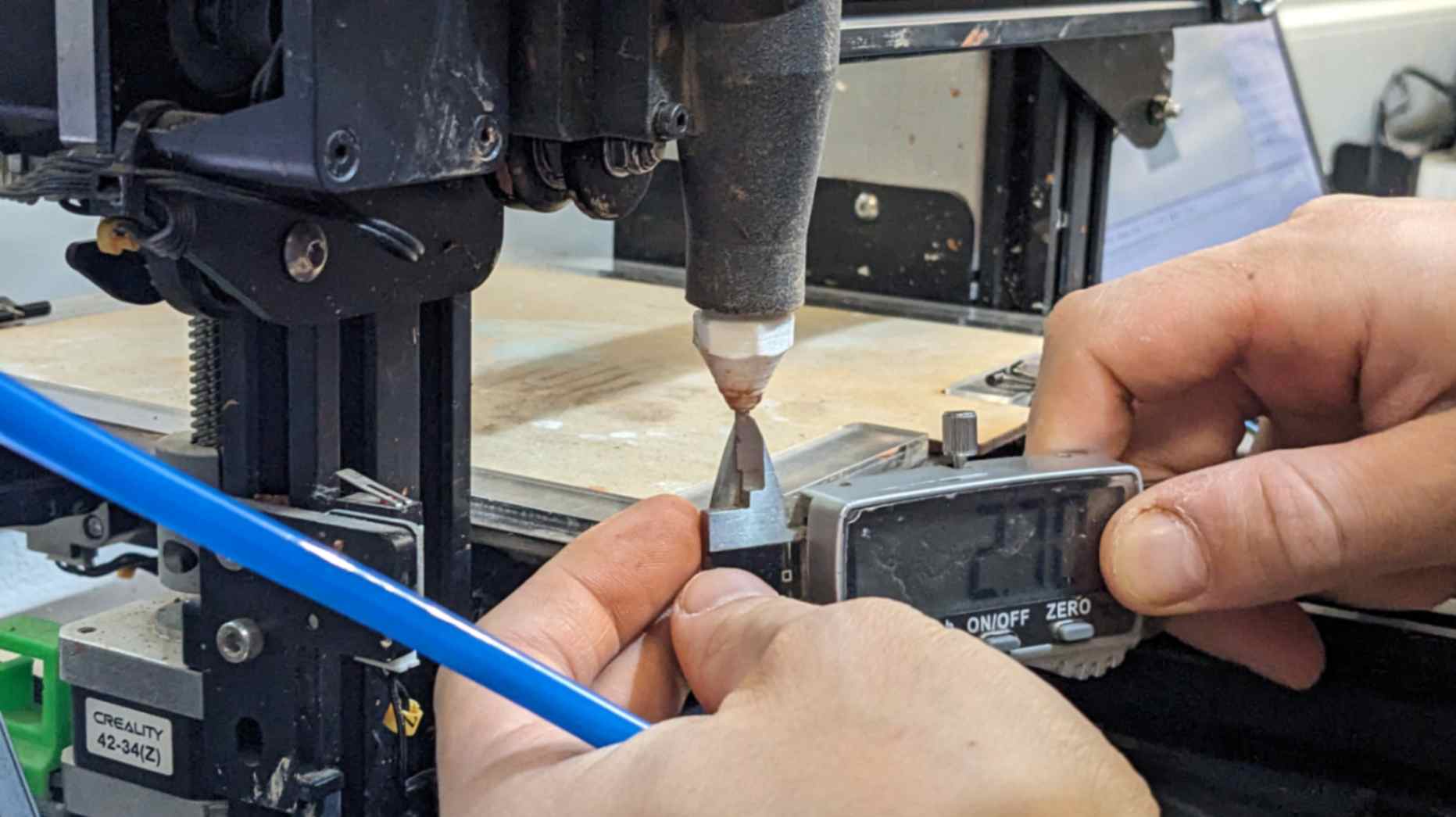
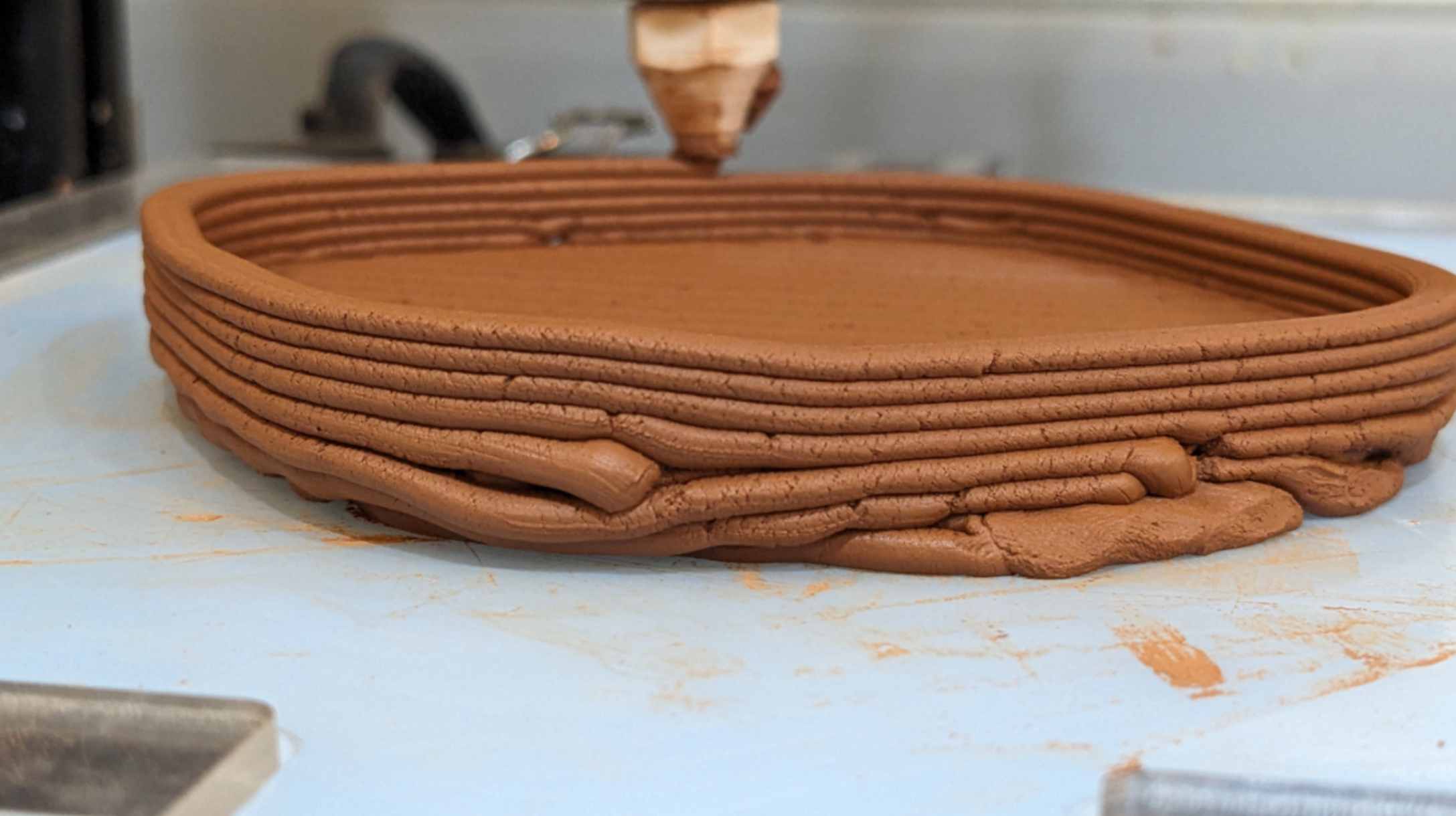
Something to remember, the workflow always remains the same but the parameter for file and print set-up will change depending on the model, printer, and the paste. So it is important to test print a few layers of a model to find the right ratio for feed rate, flow rate, air compression, and Z-axis height.
I enjoyed paste printing a lot. I would like to experiment further and also I would like to try putting them in a kiln and glazing too.
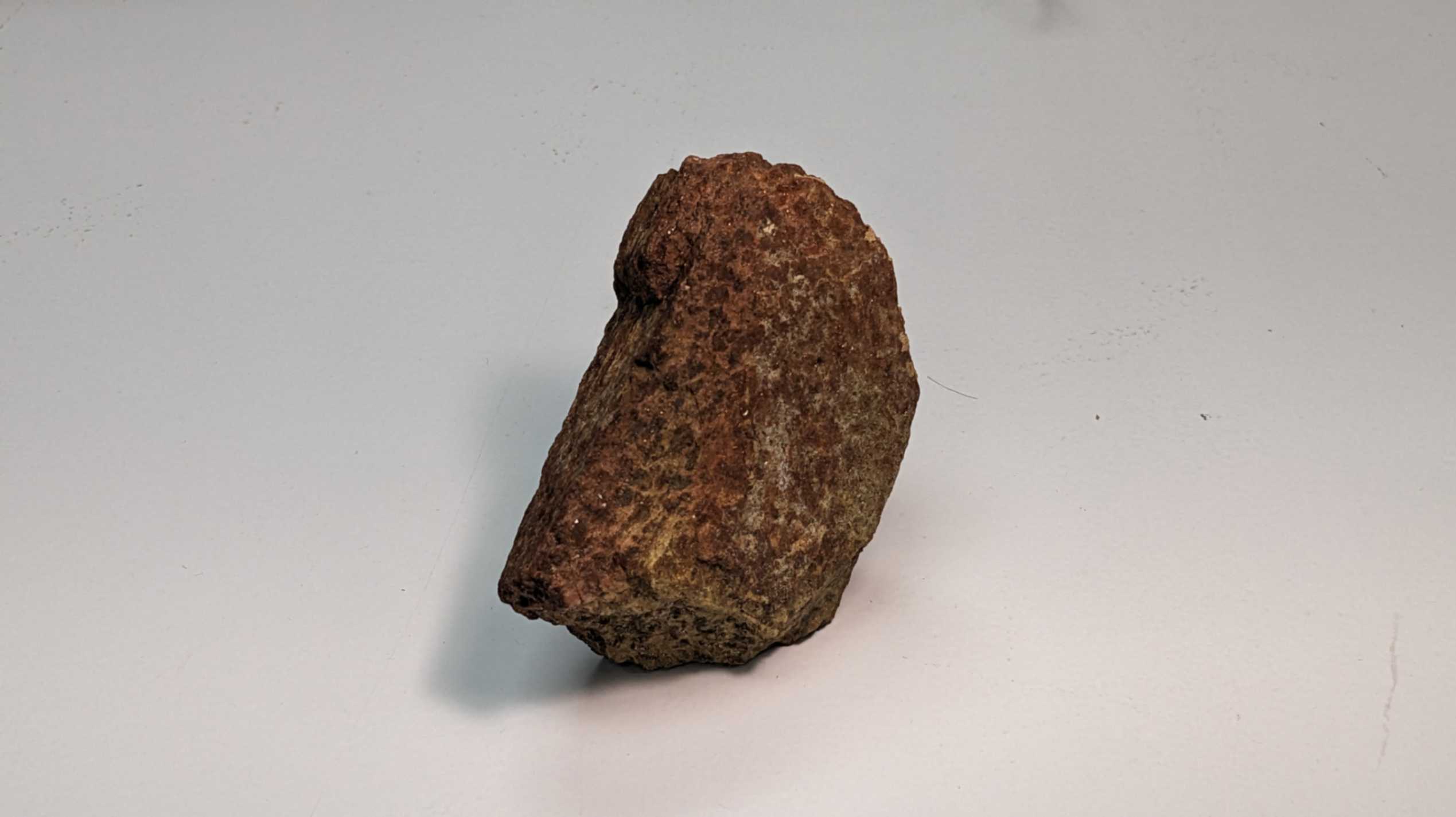
Scan to Print
This week on Friday, we were invited to Valldaura Self-sufficient Labs which is IAAC’s campus focused on self-sufficient habitat research located in the Collserola Natural Park. It was an amazing opportunity to see all the projects and have Calcotada/Barbecue with MAEB students. Thanks to my tutors who organised this event.
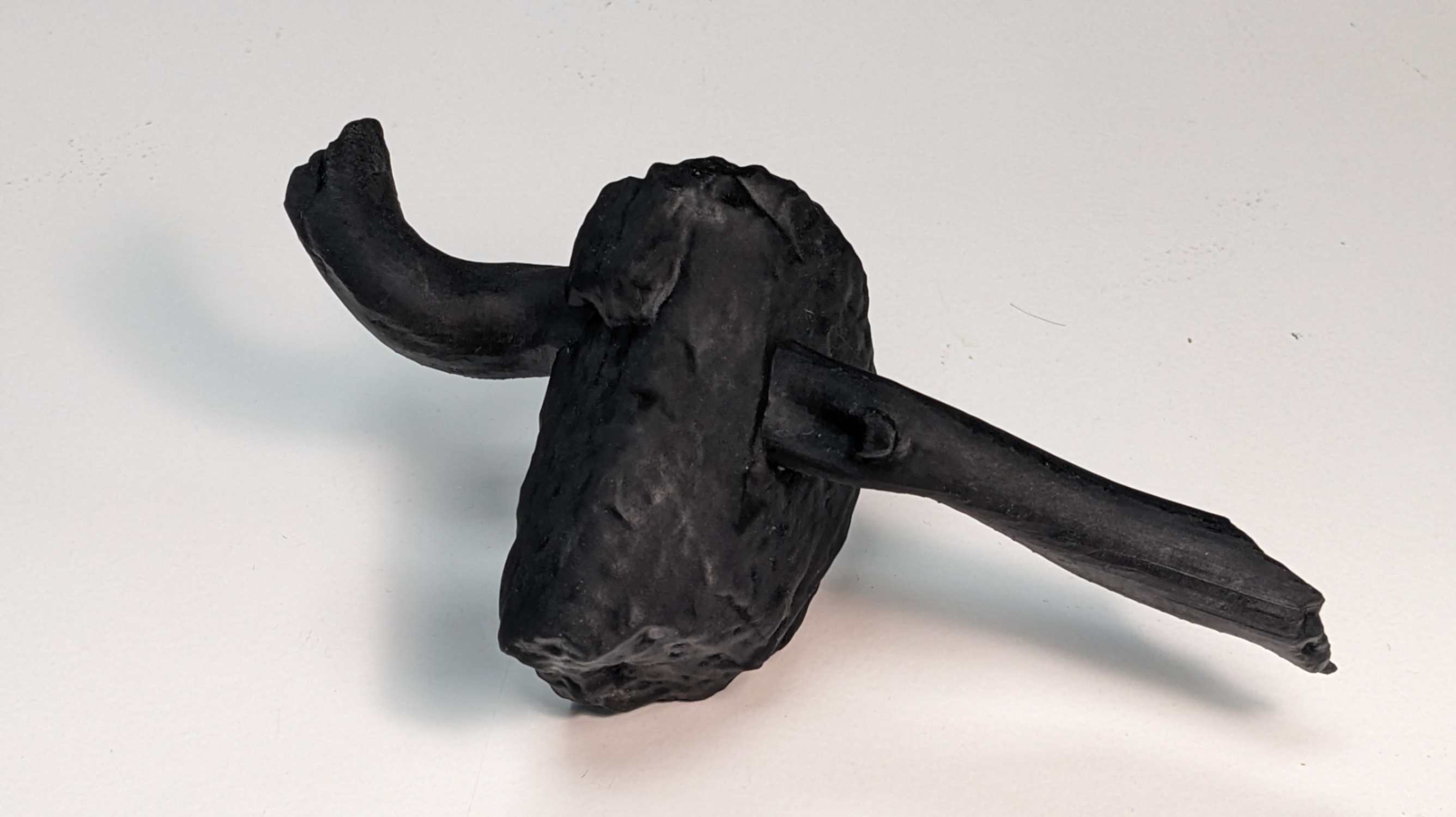
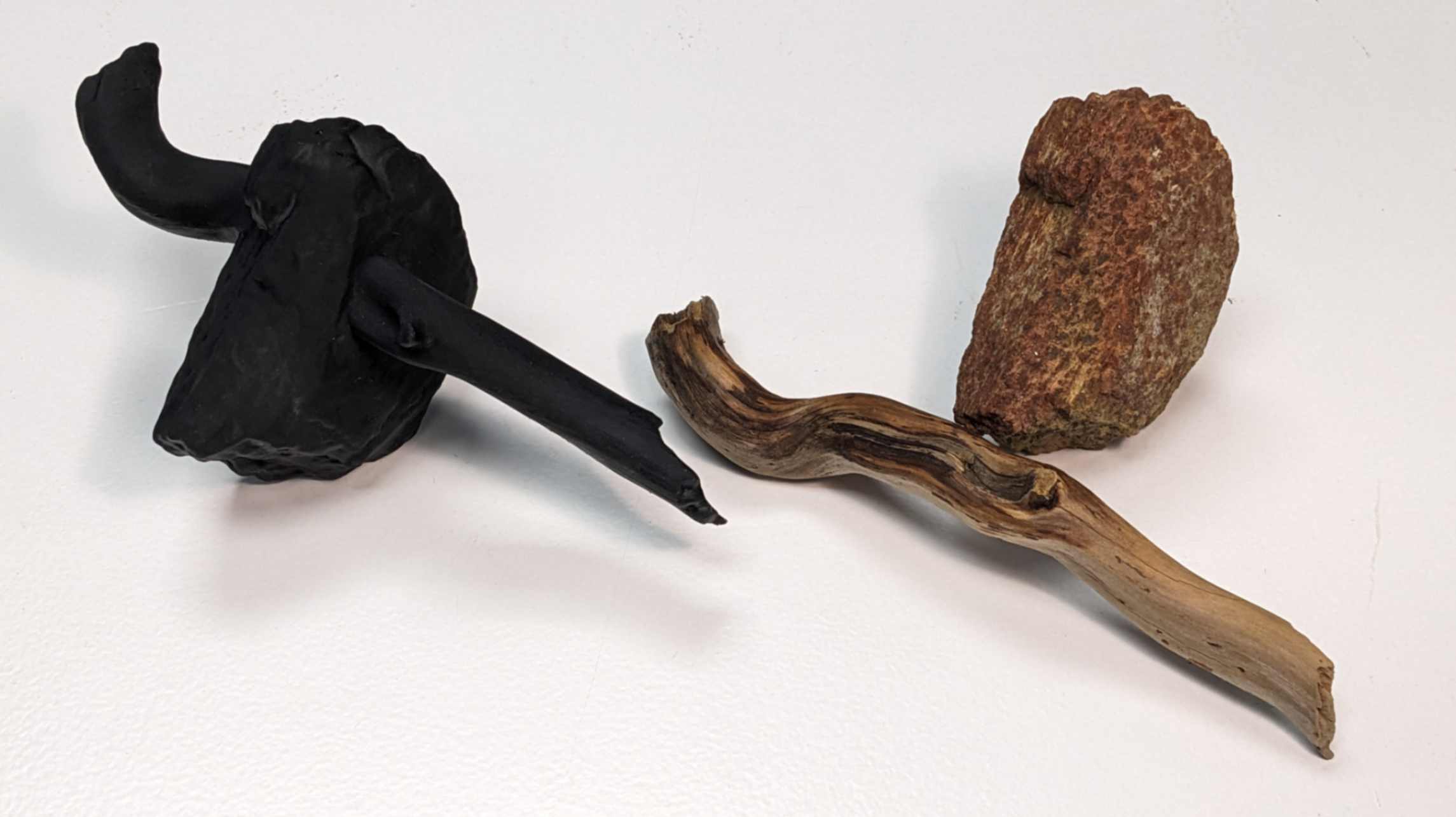
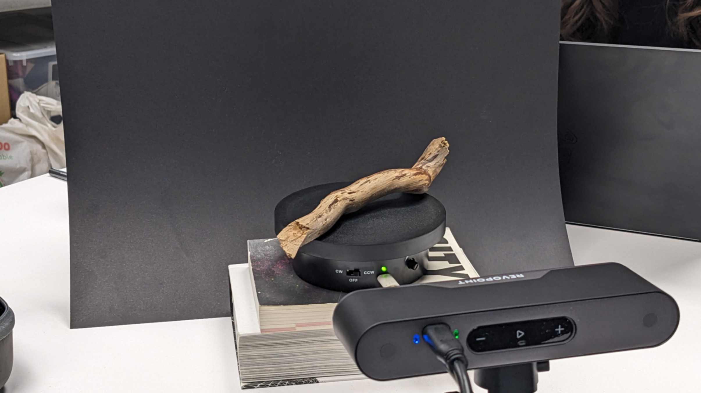
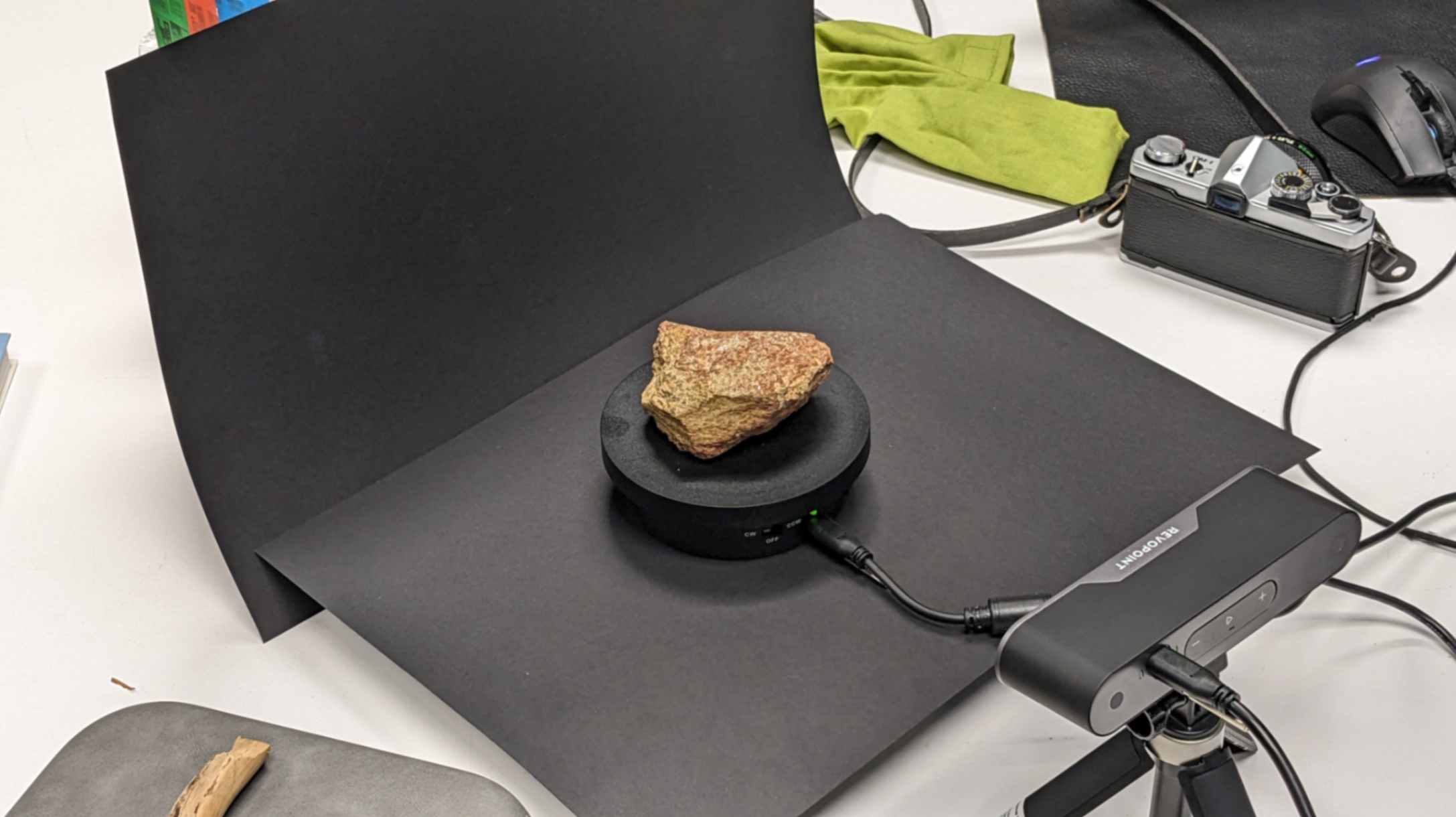
After the event, I hiked down with my classmates and picked up a stone and a wood branch. Because both of them had nice organic shapes and textures, I wanted to 3d scan and possibly 3d print them.

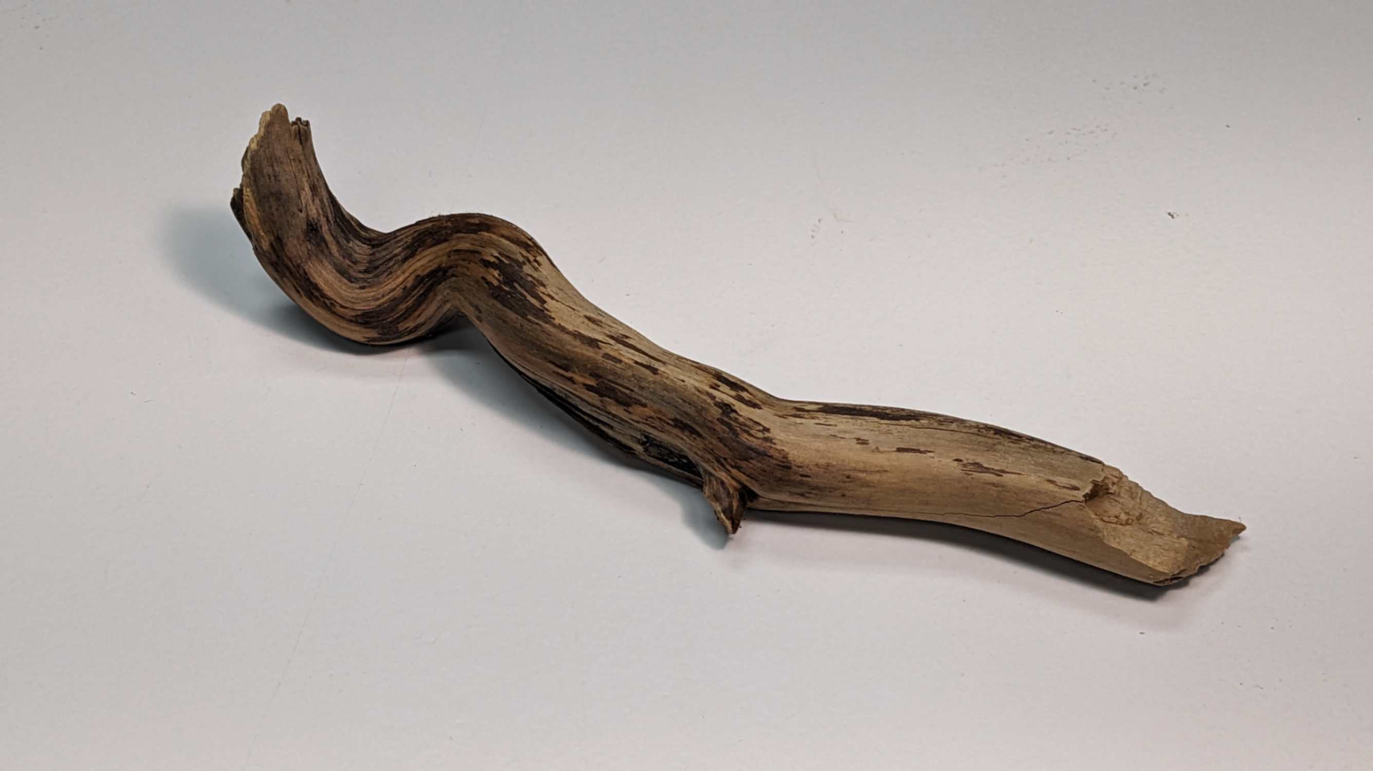
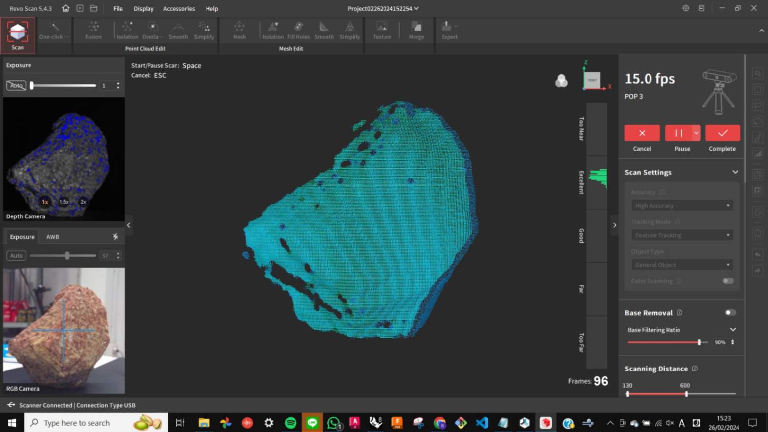
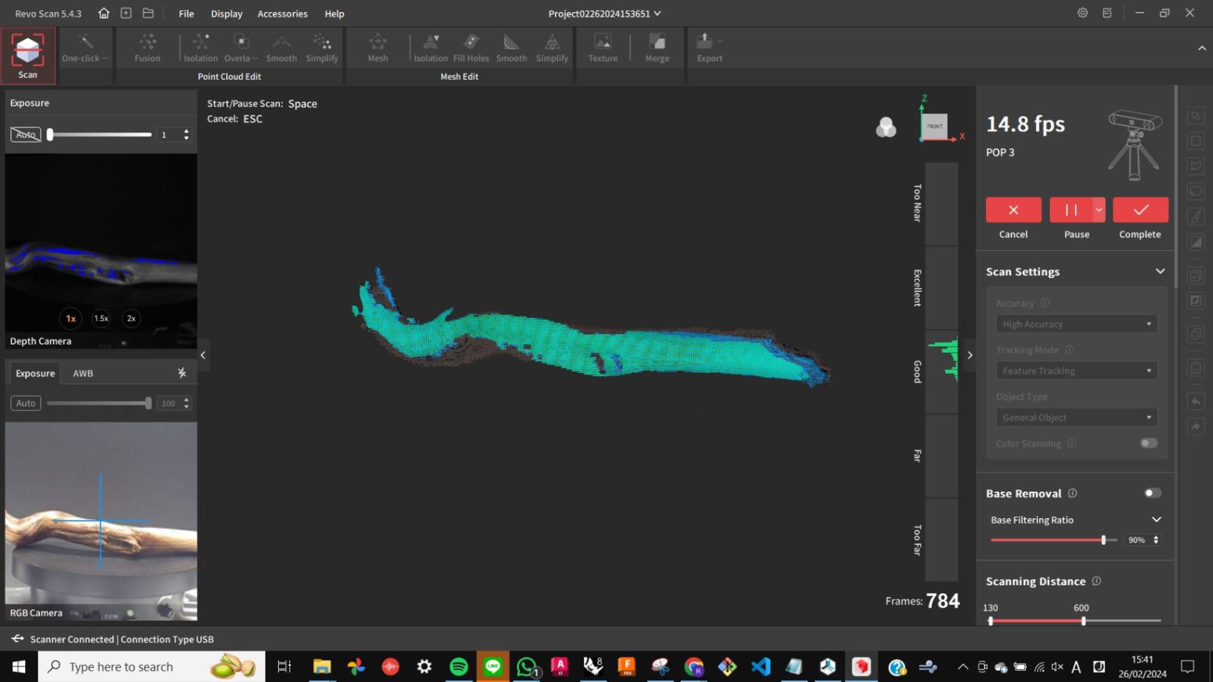
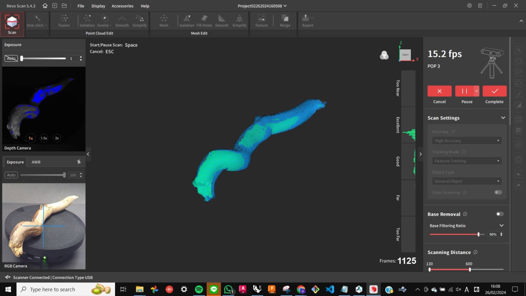
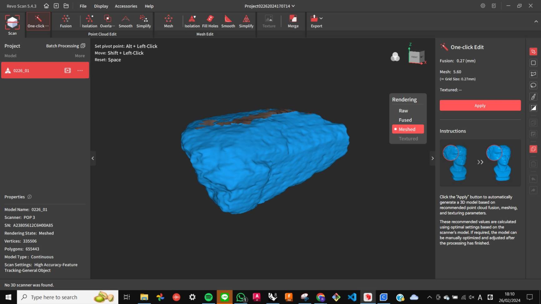
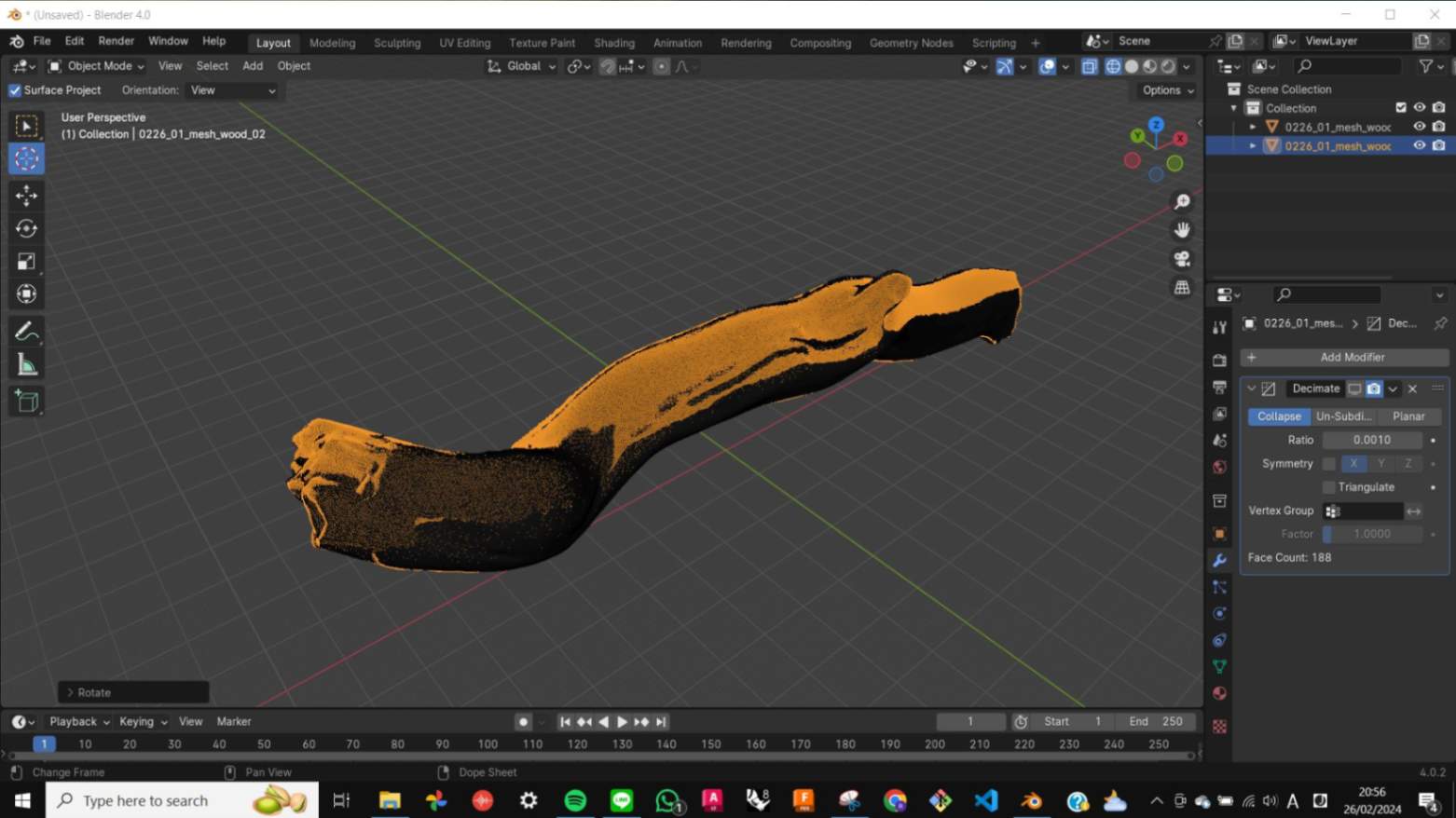
Scanning
I used REVOPOINT POP 3 3D Scanner and Revo Scan software. Since the object is small I used a turning table to help scan 360 degrees in consistent movement. At first, I scanned with the default setting but later I realized that it would scan the surface better with Auto Exposure and LED light on. I scanned from 2 different angles (top and side) and 3different sides for each object.
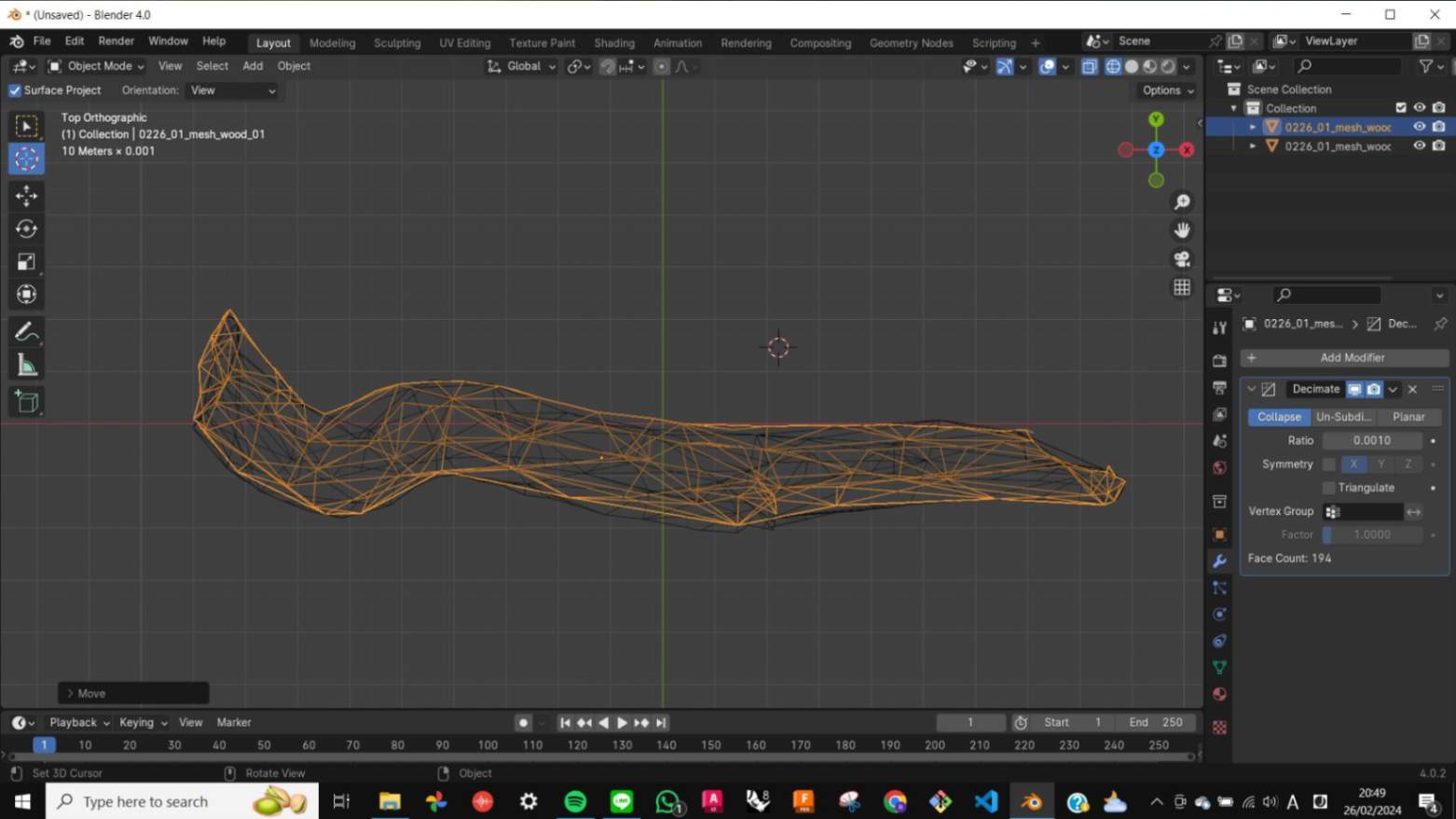
Fixing Mesh
Scanning was easy, but fixing scanned mesh was painful. It is almost impossible to scan an object entirely with a single scan because it will always have at least one side that cannot be scanned (like the side touching a table). To have an entirely scanned object, I needed to scan multiple sides and put them together in post-processing.
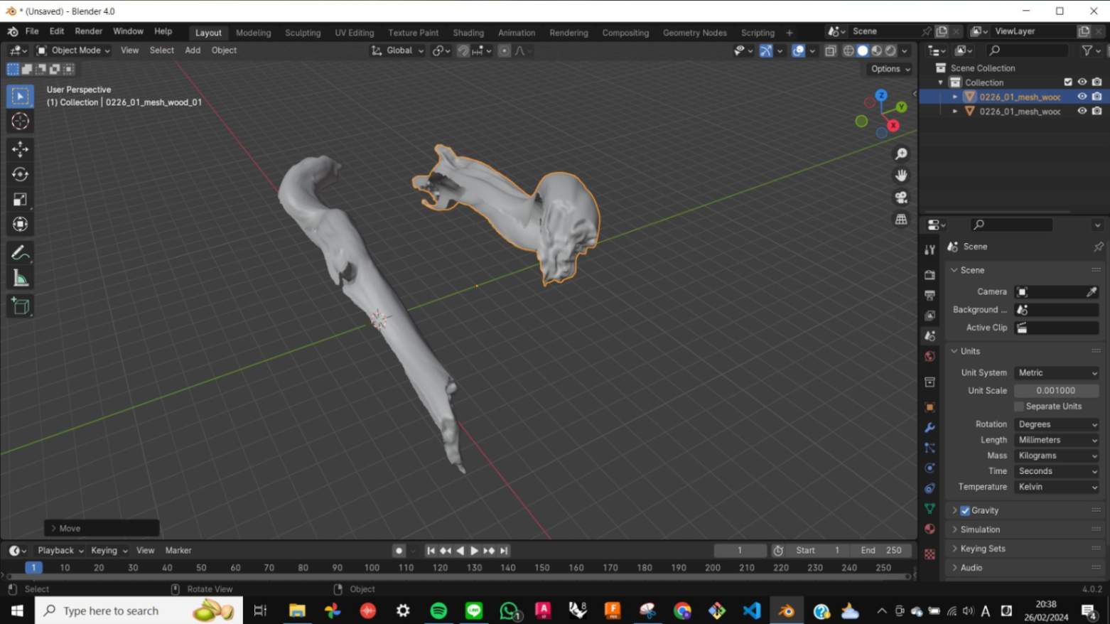
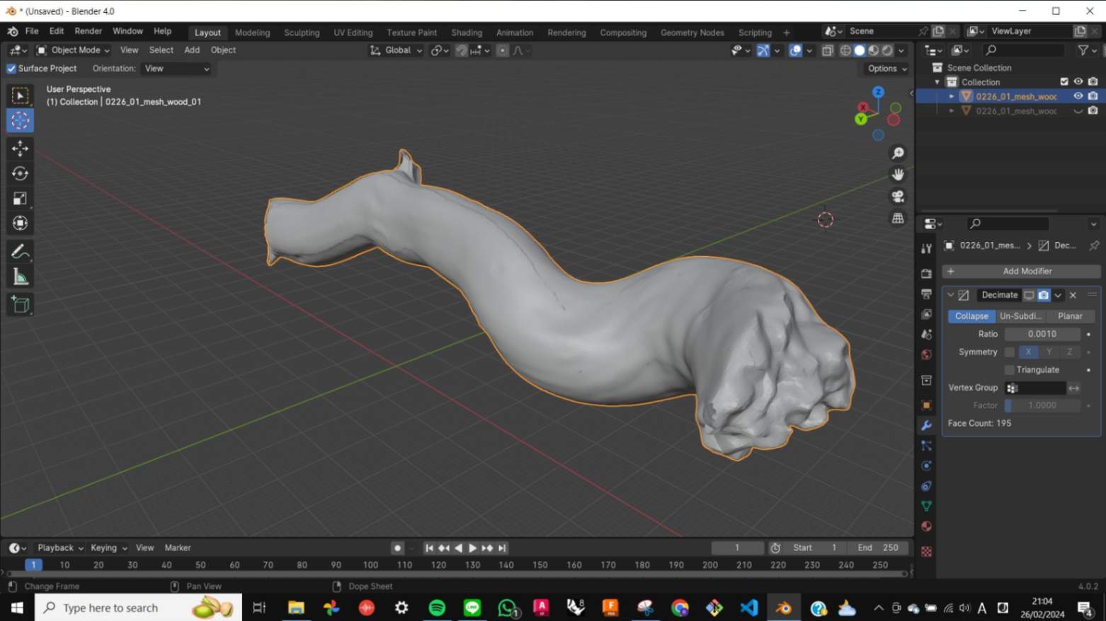
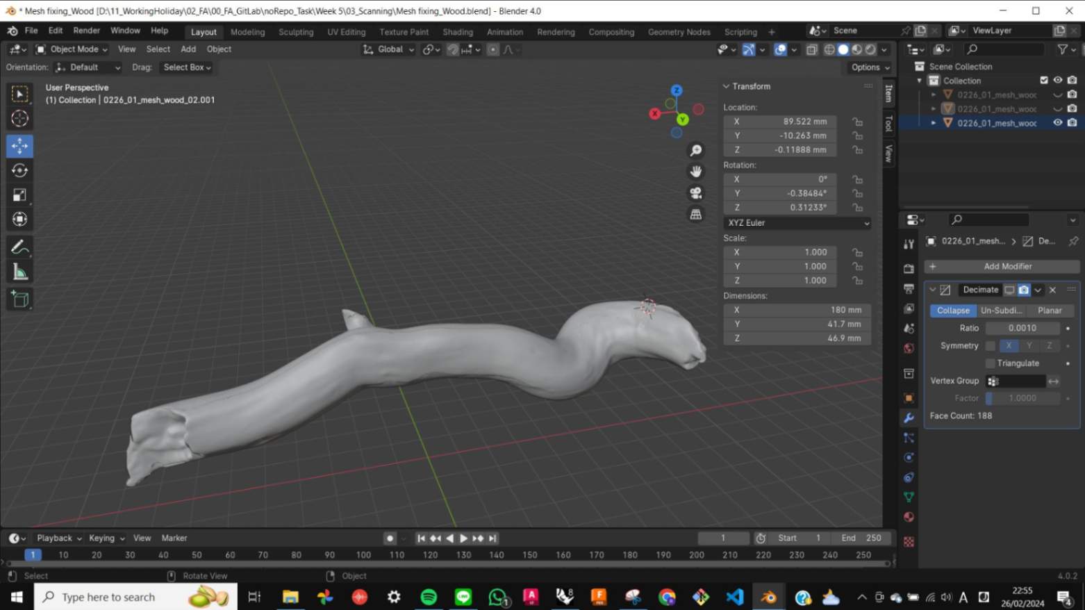
To do that, I was advised to use Blender or Meshmixer. Since I already have a little bit of experience with Blender from Week 2. I decided to fix the mesh in Blender. The fixed mesh workflow in Blender is below.
- import scanned mesh models
- Align them as much as possible by repeating Grab and Rotate
- Choose a mesh model, and patch the blank side by copying meshes from another model. In Edit Mode select face and Ctrl+[+] to increase selection.
- Join and merge mesh
- Filling the holes, Ctrl+RightClick to select loop edge, [F] to fill
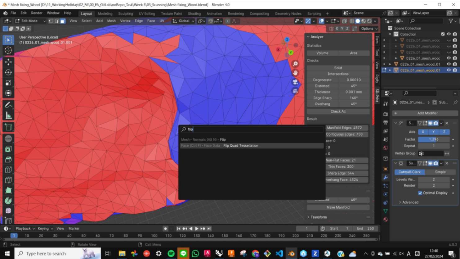
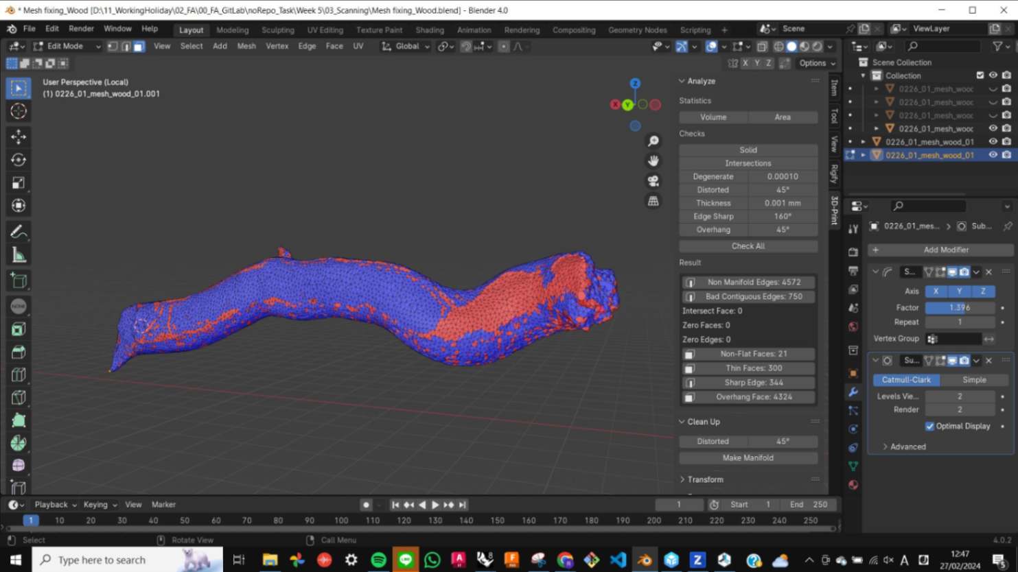
- F3 to Flip faces
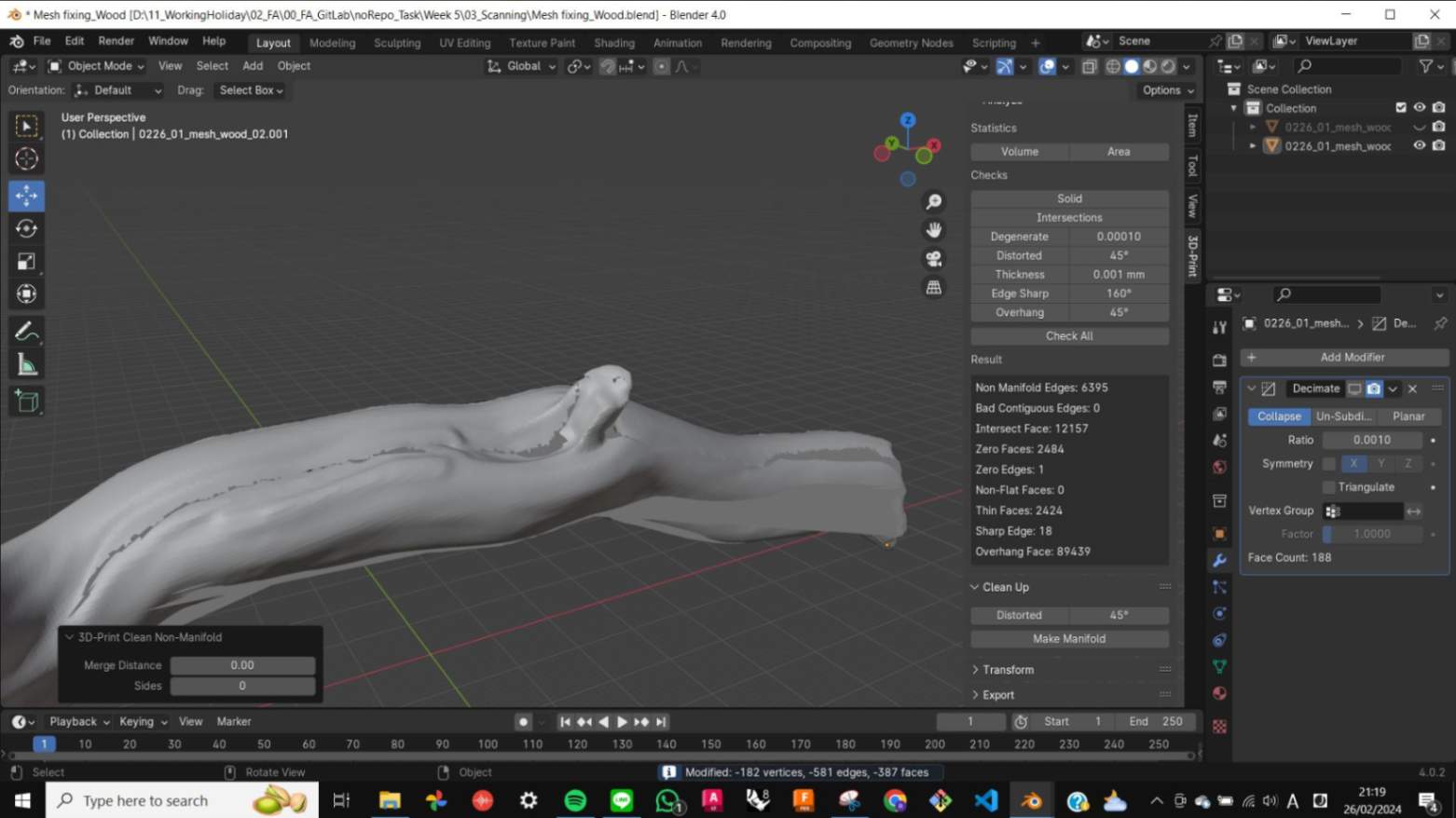
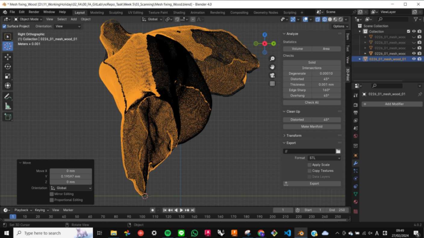
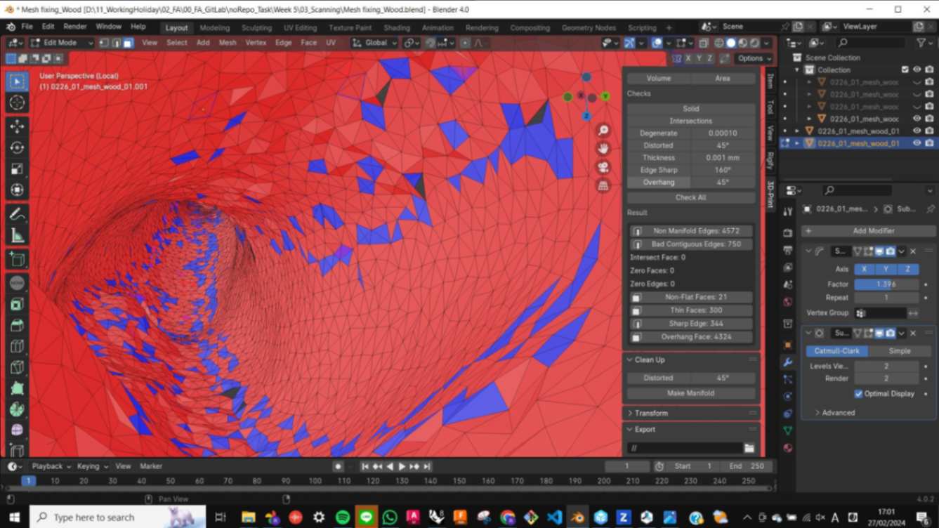
- Activate the 3D Print view tab to check the mesh for 3D printing. Check All
- Make Manifold to fix the mesh automatically
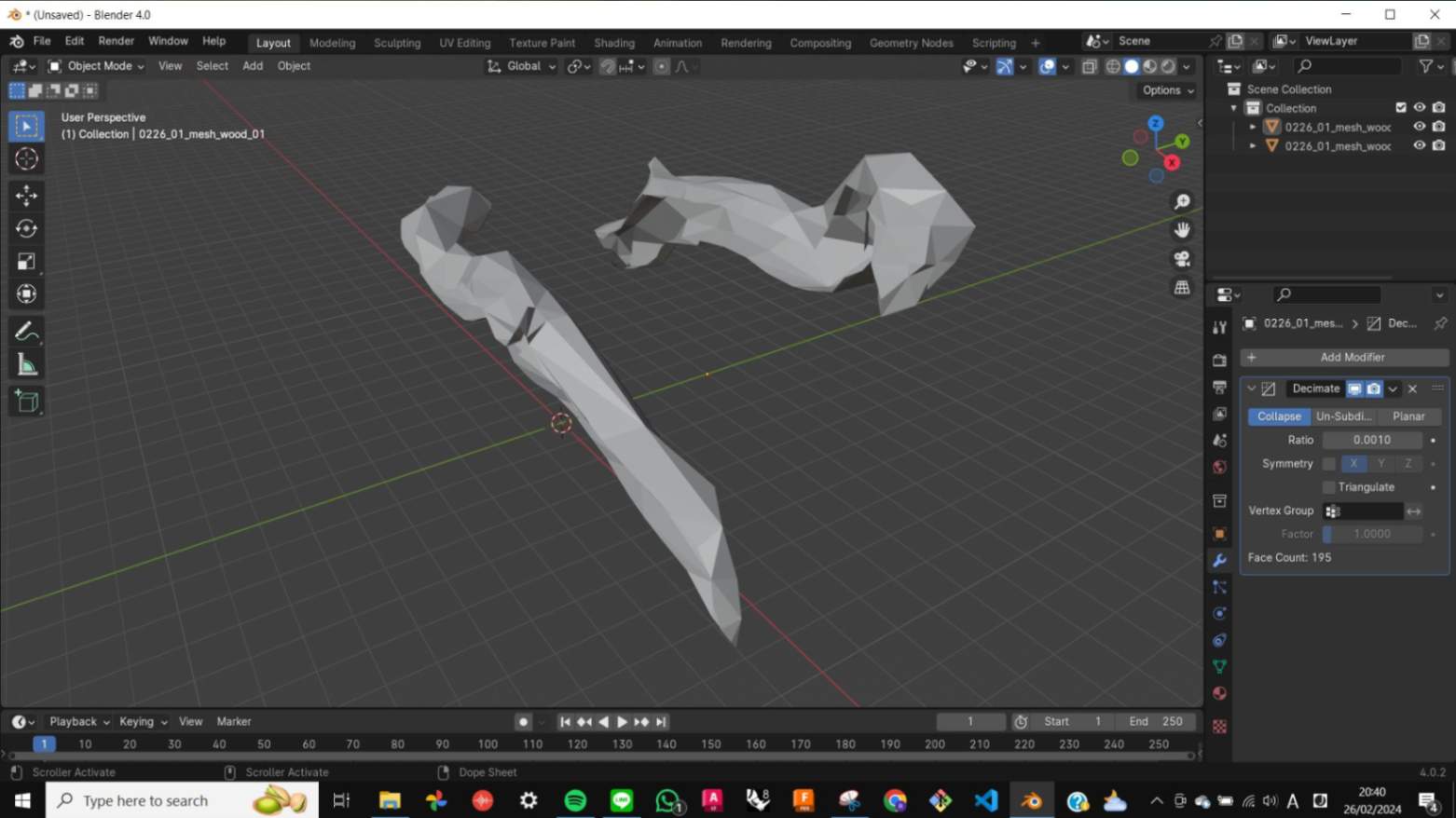
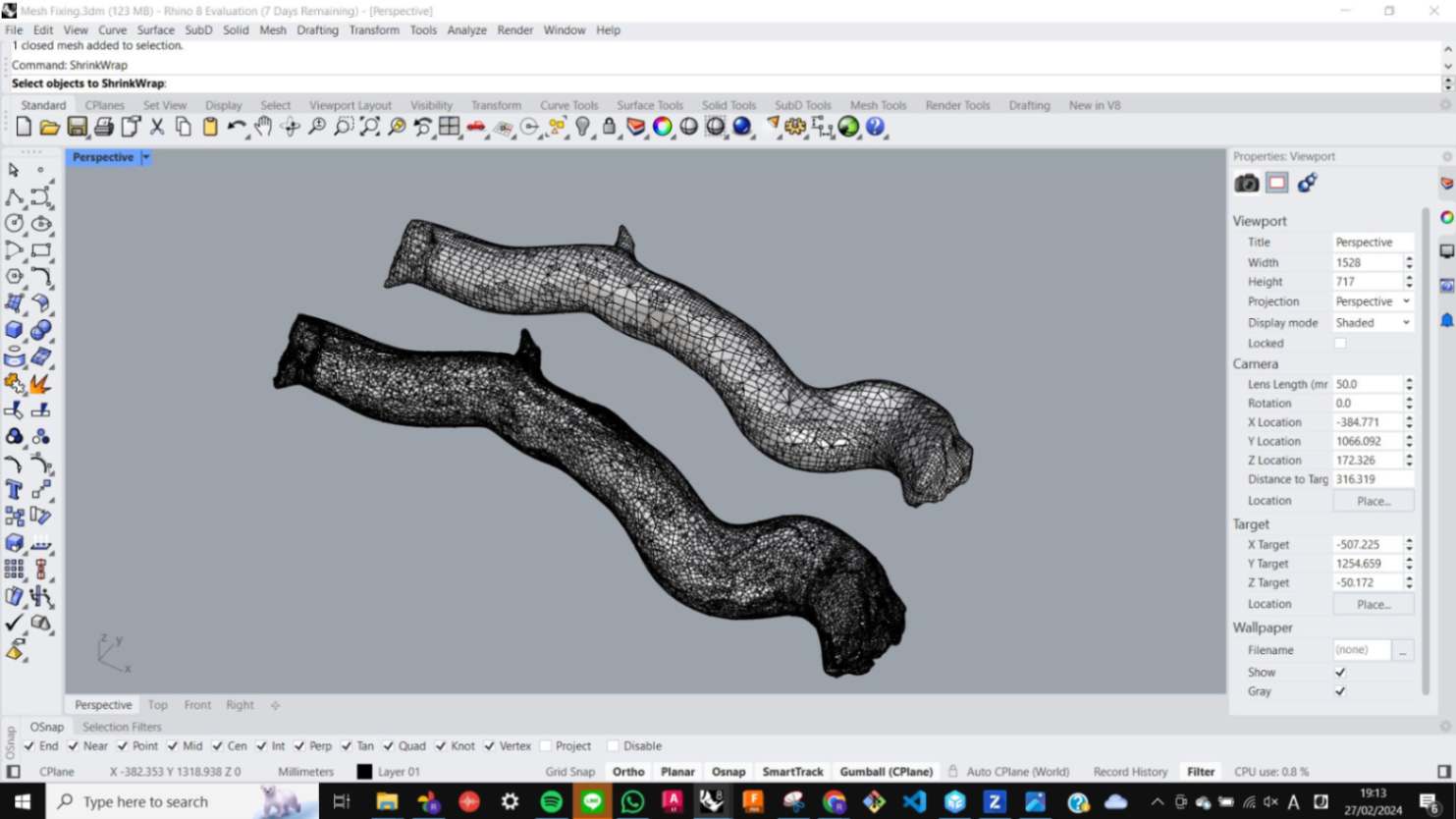
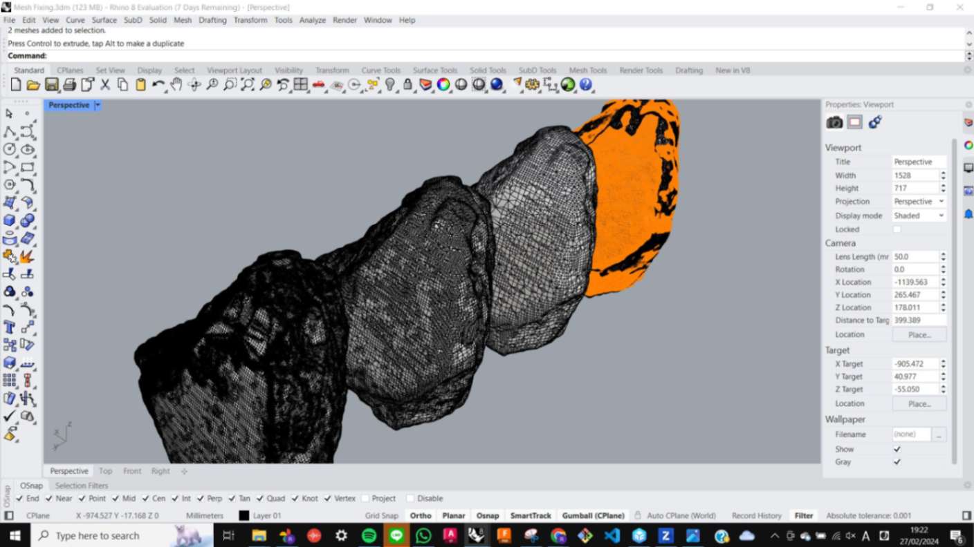
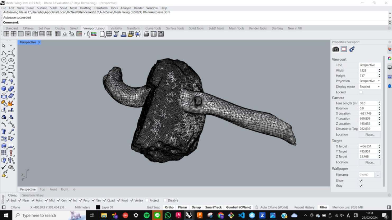
It was a good exercise to get back using Blender again, however for my model Make Manifold command was only making distorted meshed models so I needed to manually flip the faces one by one. This process was insanely time-consuming and eventually, I gave up fixing this in Blender. To do this in different software, I also tried to use Meshmixer, Revo Scan, Z-Suite, and Rhino but I was not able to find a quick solution for any of them. As I was giving up this experiment, My classmate Susan told me about the Shrink Wrap command in Rhino. It covers the mesh model with another mesh and creates a closed mesh. To be fair it is not the perfect solution but at this point, I thought it would do just enough for what I wanted to do. With Shrink Wrap, there are values for distance to determine how detailed the Shrink Wrap mesh should be compared to the original mesh. When I made it too detailed it was detecting more broken meshes and distorting the model, so I eventually decided to use 0.5mm distance because it was the minimum detail I could use without distorting the model. For the print model, I simply merged the stone and wood branches in a way that is not possible to do with the original object.
Printing
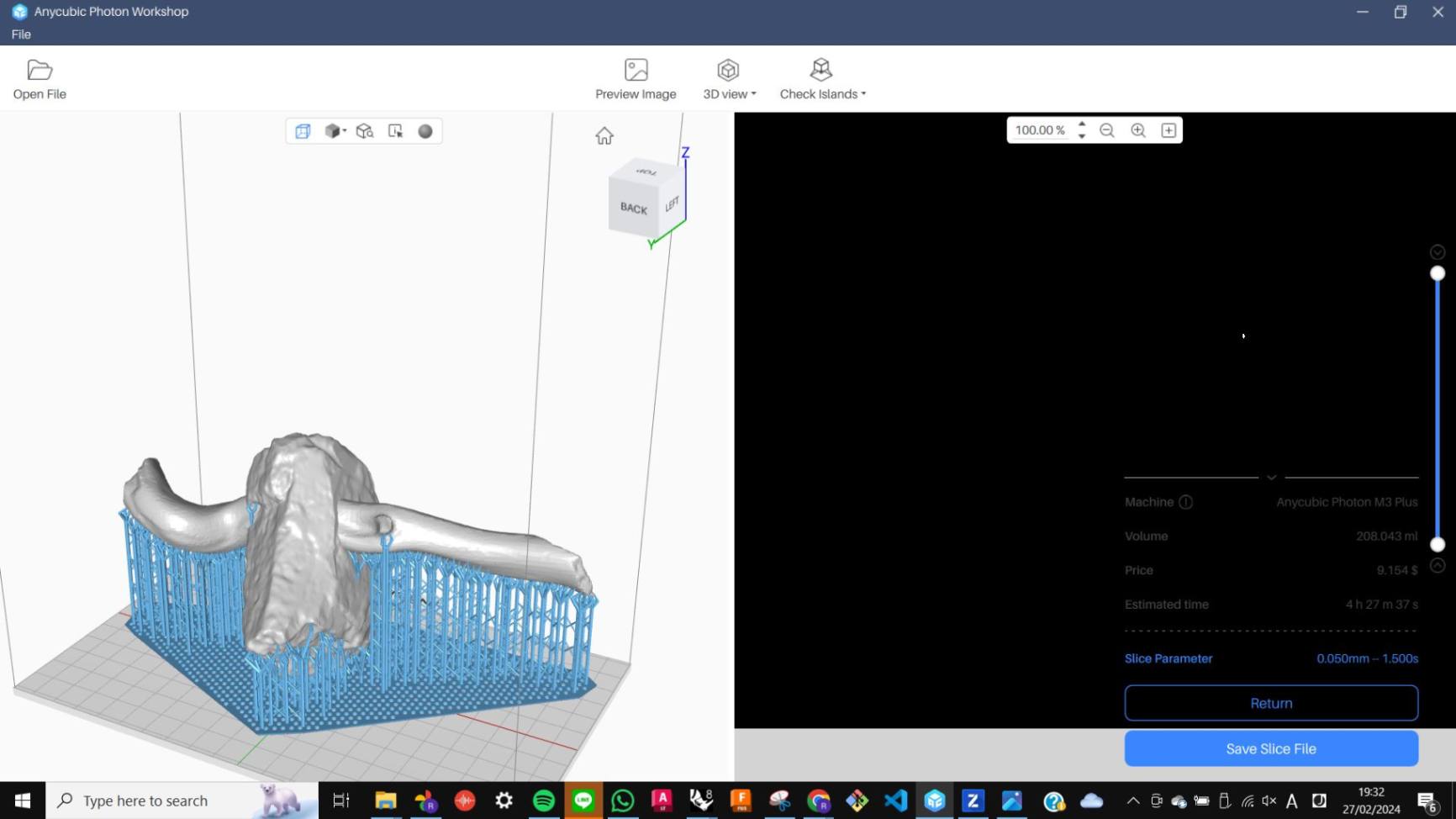
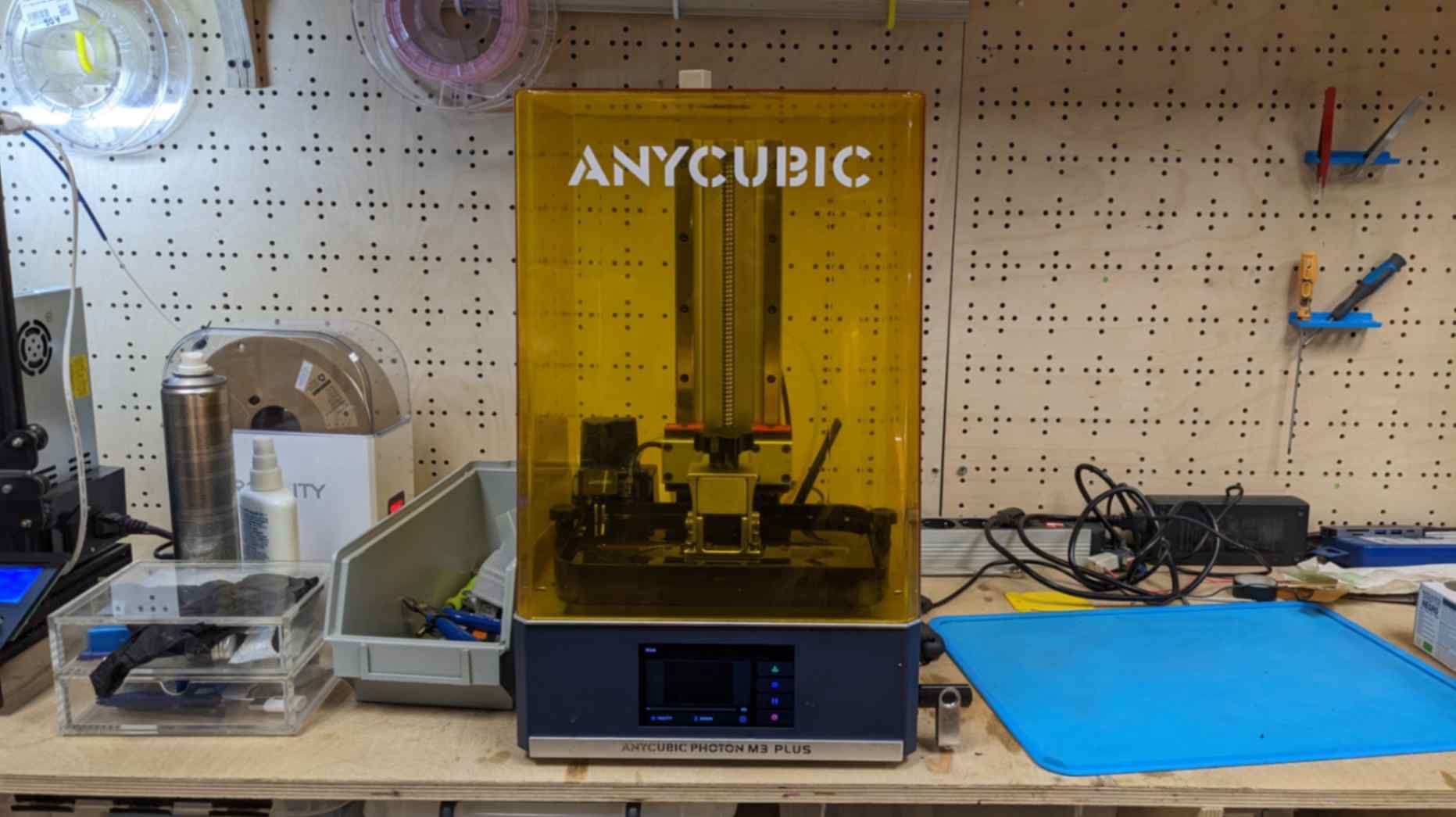
For printing, I decided to use ANYCUBIC Photon M3 Plus because it is a different printing method compared to what I have printed previously and also it will show detailed texture on the surface since it is printing with laser. For the print setting I used used printer's default setting and it took 4 hours to print.
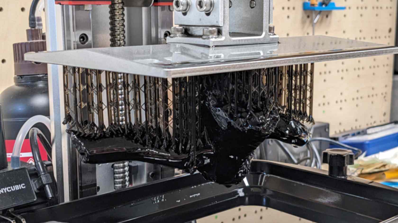
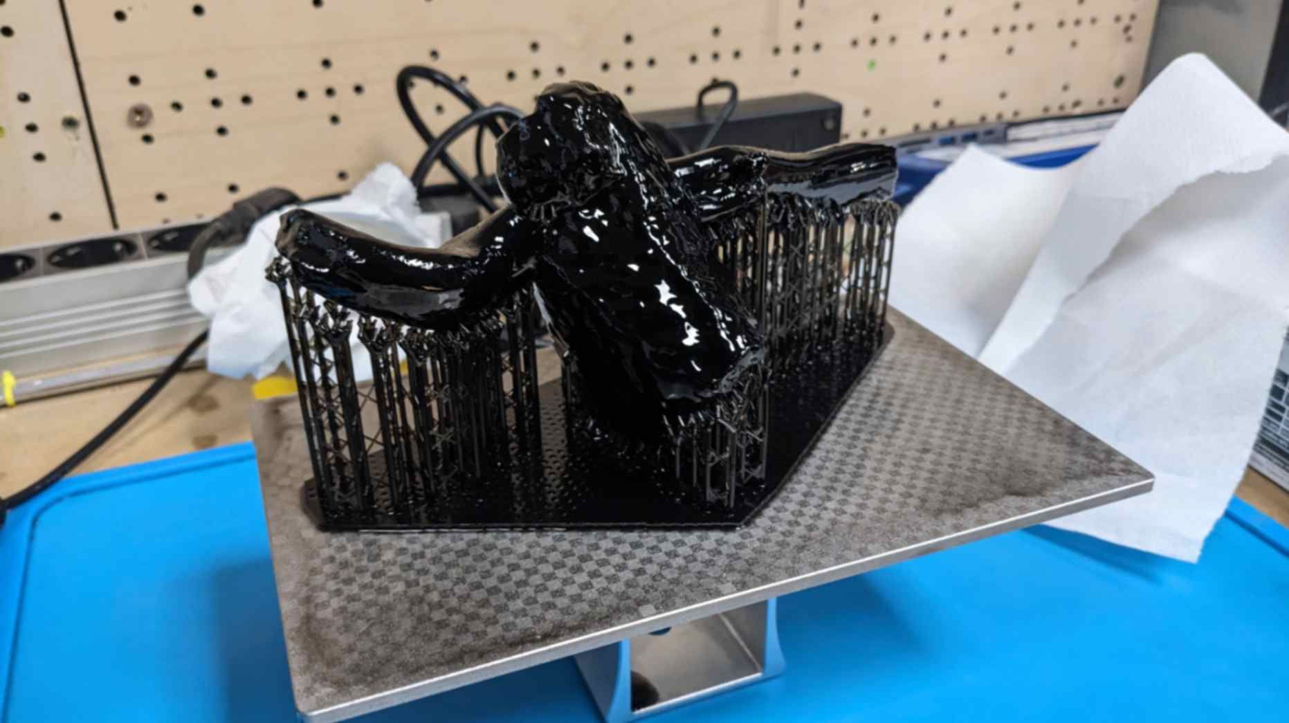
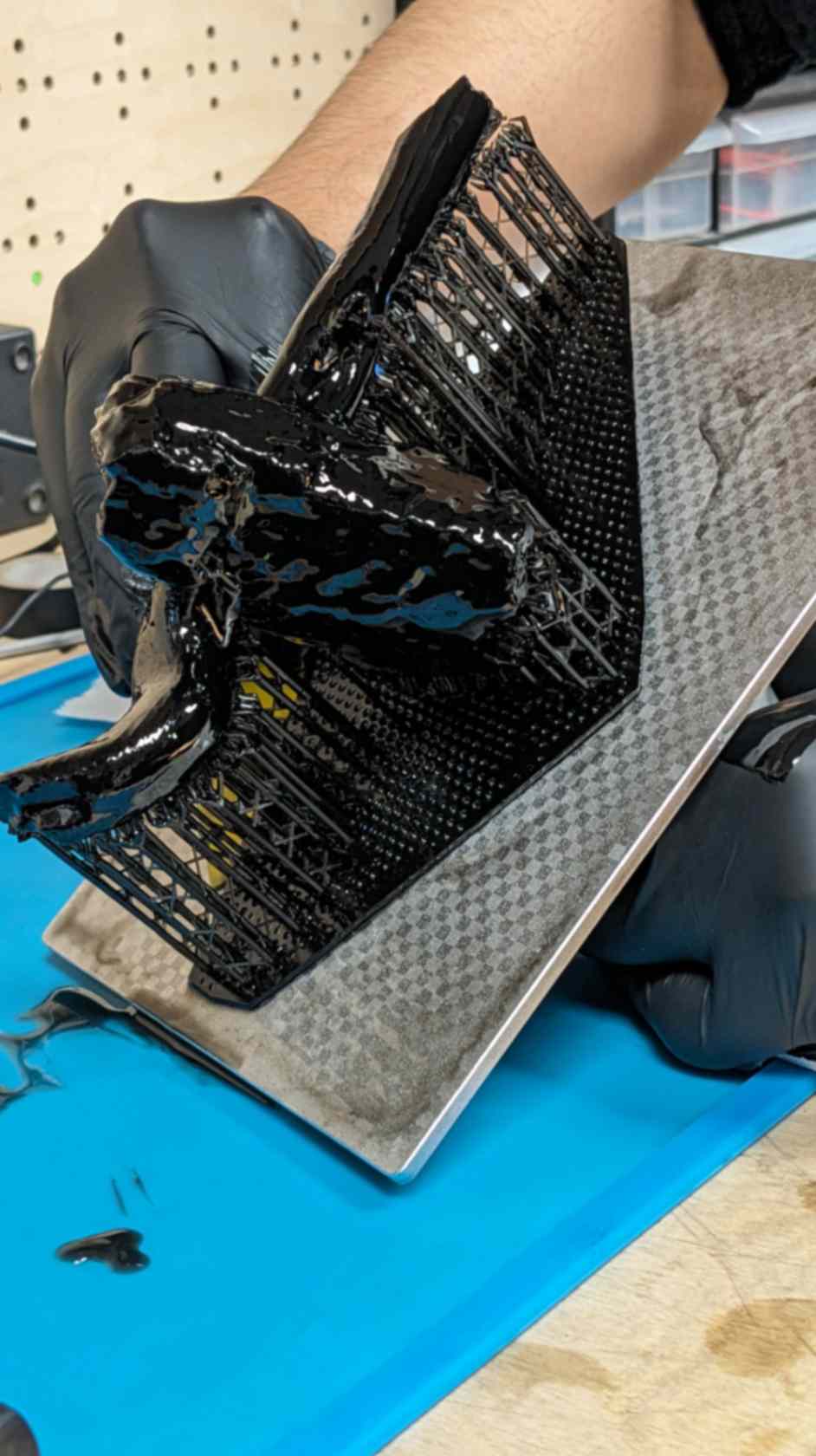
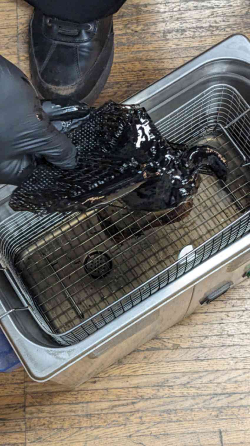
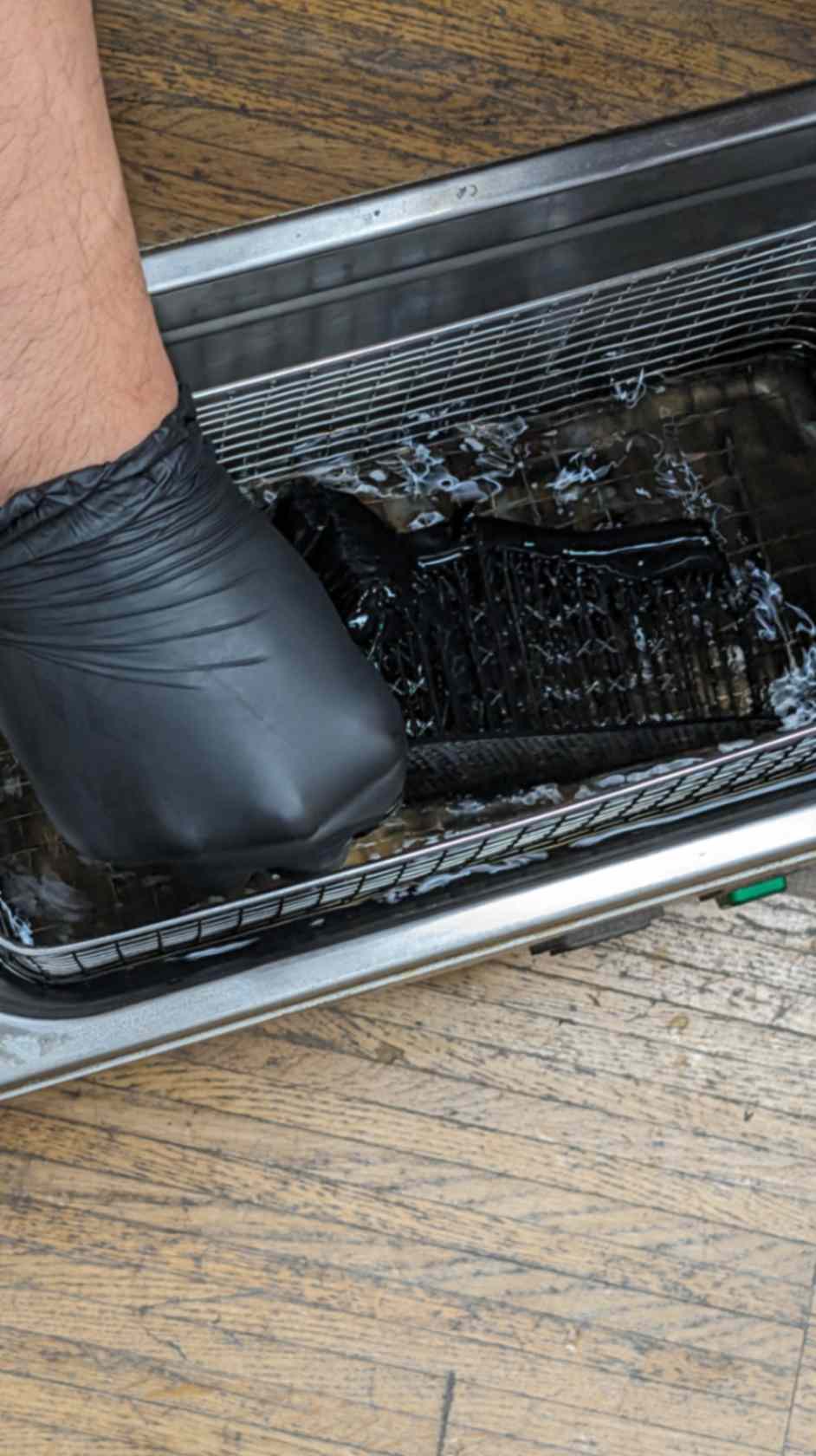
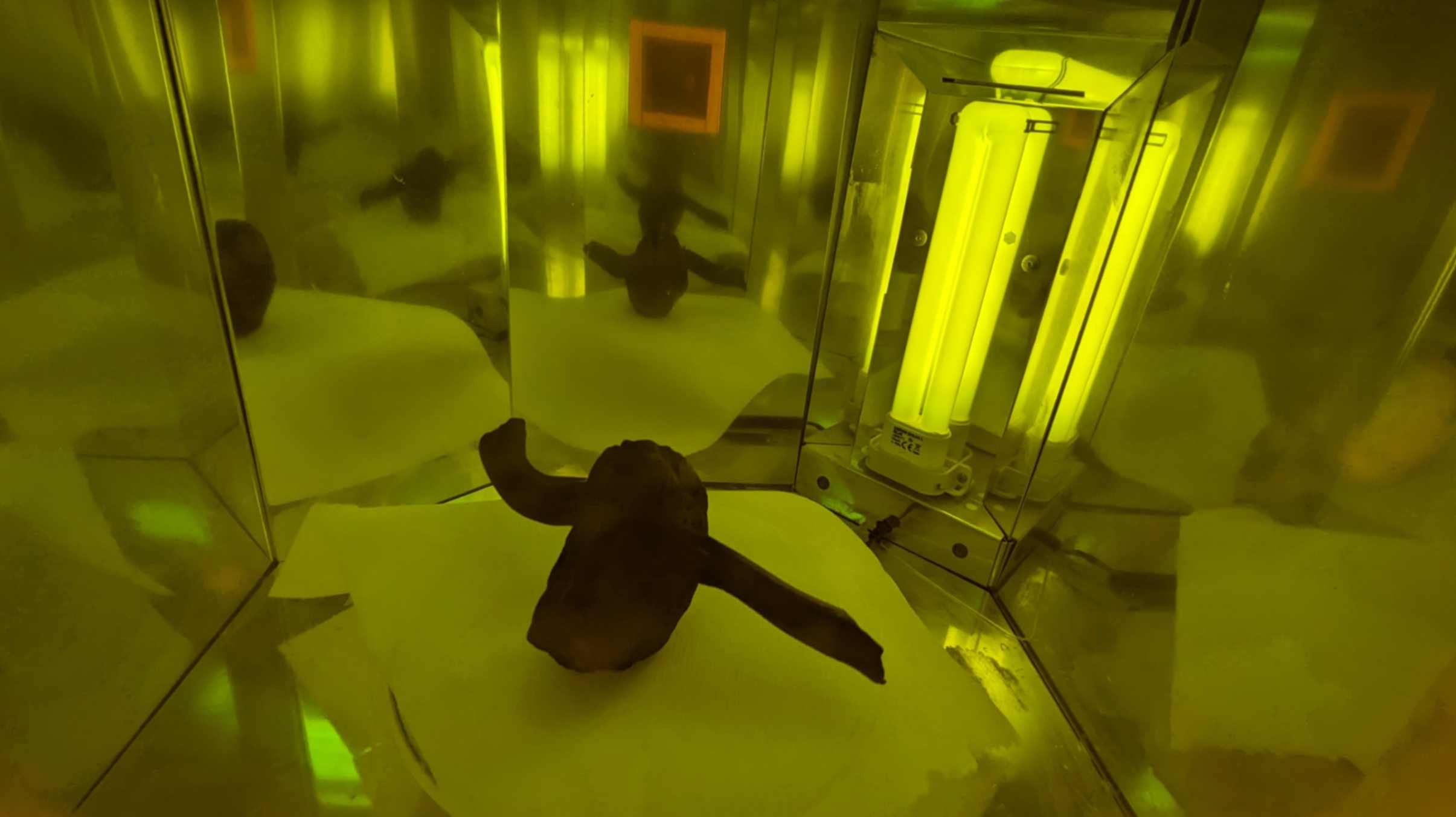
When taking the model out from the machine, it was important to be careful since the model was not cured yet and the process could be very messy. I took it out from the bed and removed the support. Then I washed it with alcohol and put it inside the UV Light box for 2 hours for curing.
Files
03_Stone_Wood_PRINT.stl
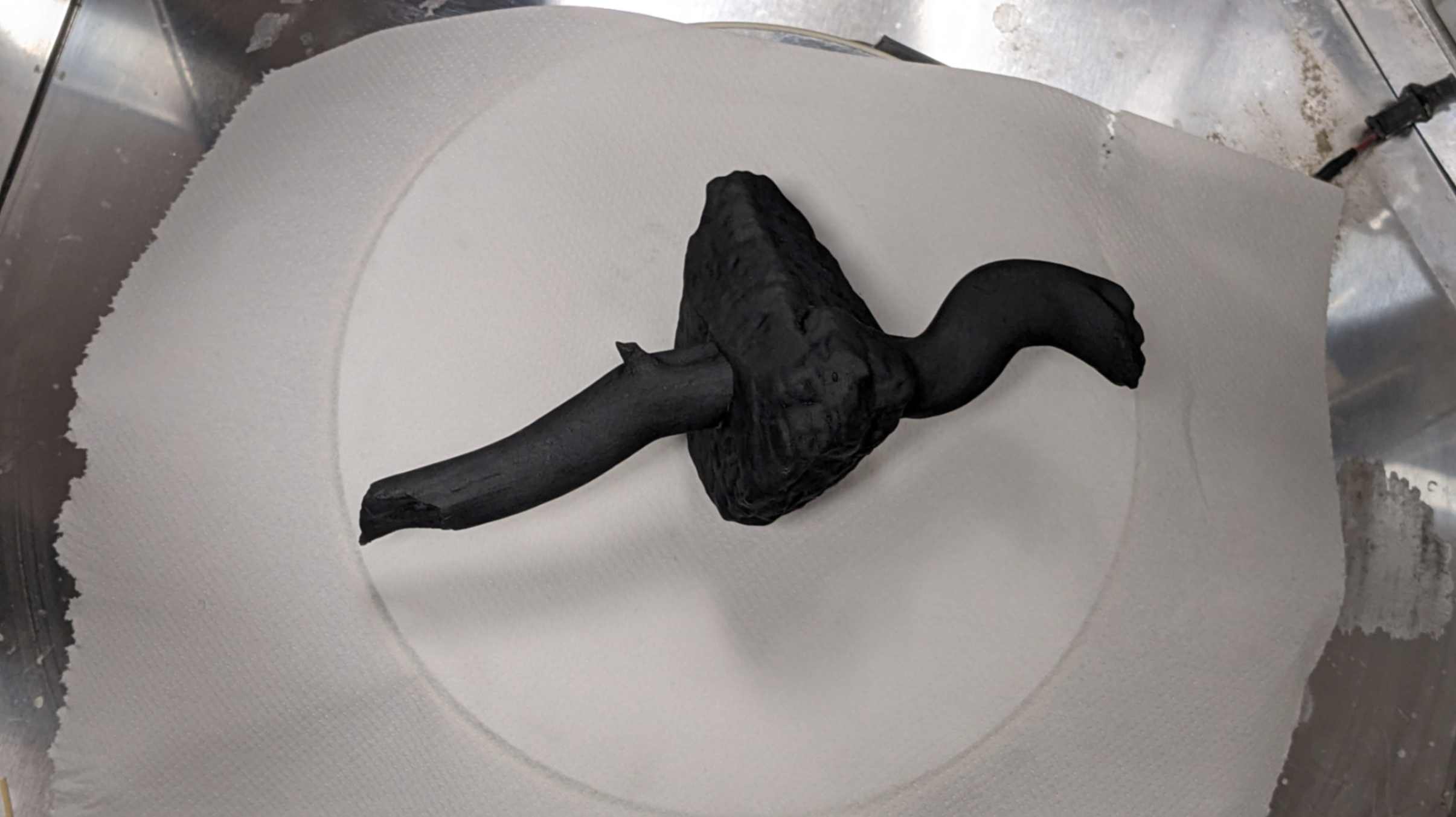
Result
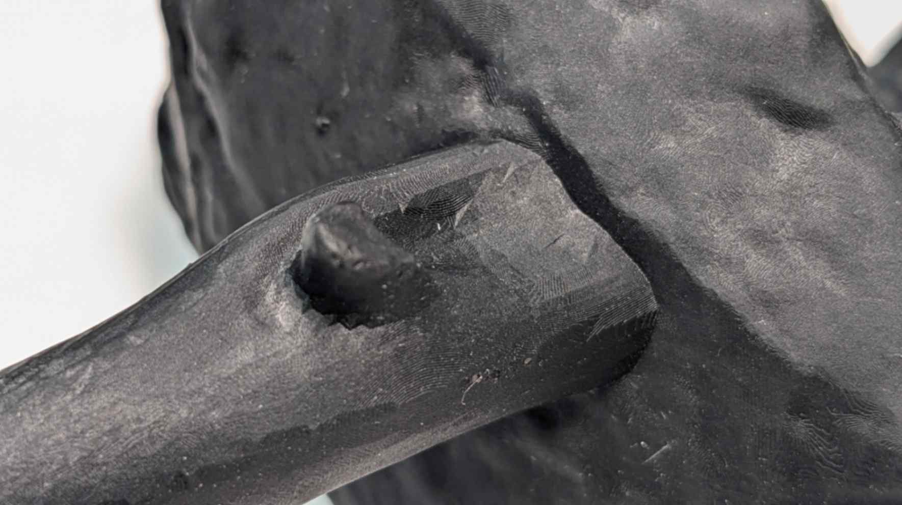
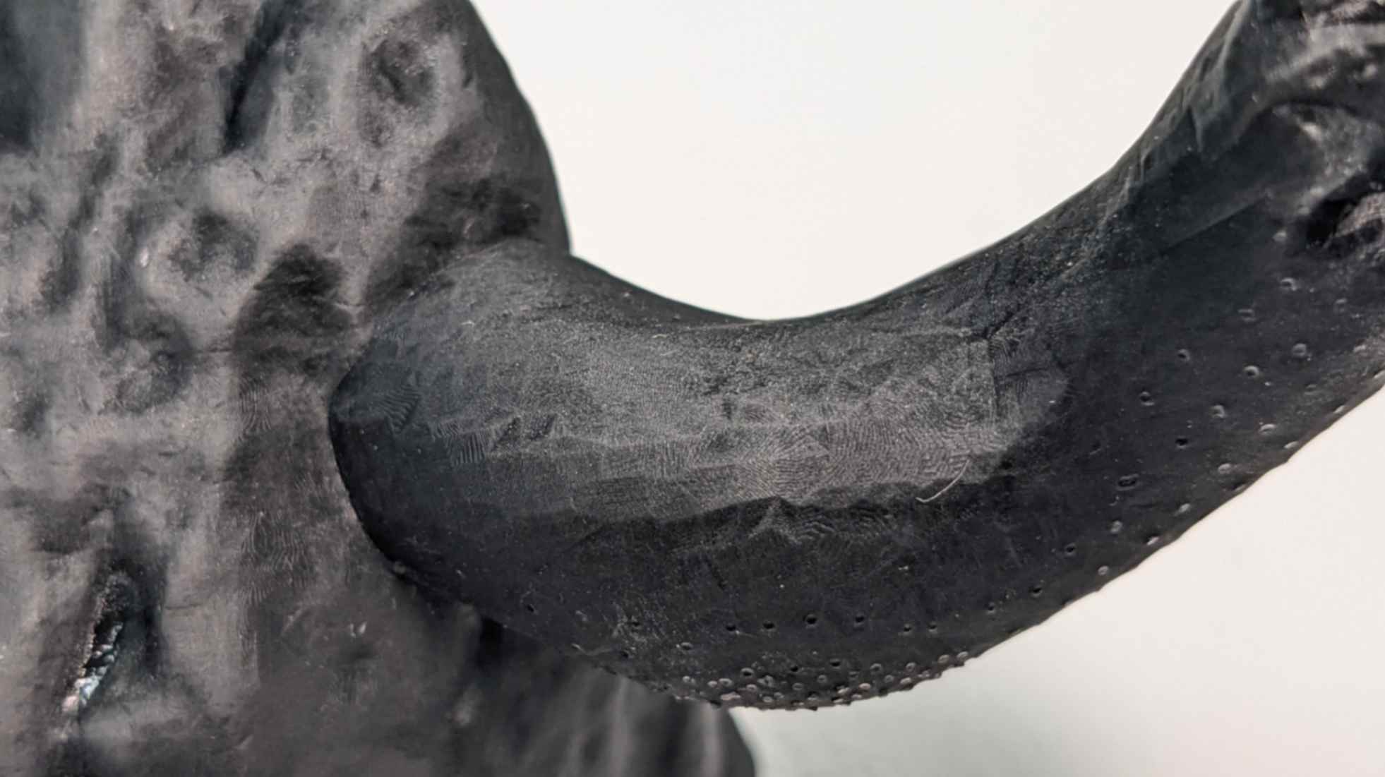
The surface and the shape were very detailed and beautiful without a typical printing surface. However, when I looked closely I could see a mesh mark on the surface. I am guessing it was caused by a badly broken part of the original mesh. Also, small dots from supporting points were noticeable however I guess they could be removed by polishing over.
This was a long and painful experiment, but I learned a lot about how to convert data between digital and analogue, and how difficult to replicate the super high resolution of the natural world into the digital world.