Week 10
Mechanical design & Machine design
Fab Academy 2024
Riichiro Yamamoto
Dear My Friend
This week we were introduced to machines and mechanics. The assignment was to build a machine as a group. I wanted to make a paste printer because my final project is related to a paste printer and because I wanted to understand better how the machine works.
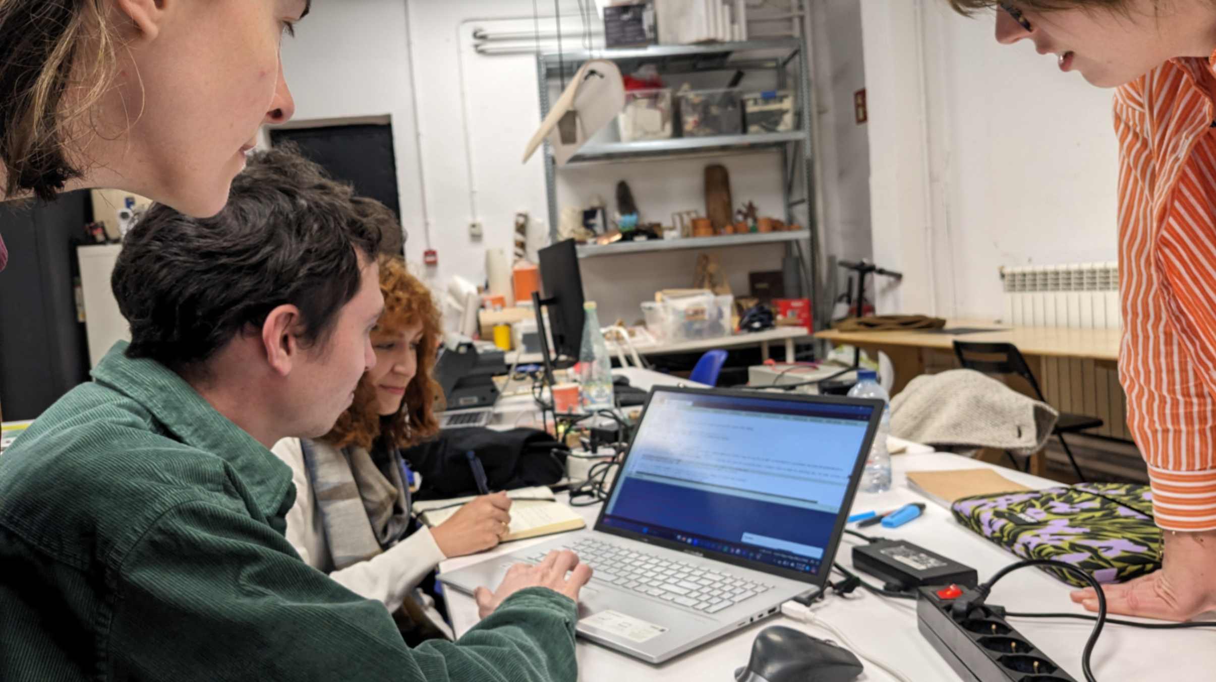
After organizing groups as a class, Andrea, Emily, Hala, Lena, and I became the Paste Printer team. We had a really good team and all of us worked very hard that we finished making our machine a few days before the deadline.
All of the process is documented in the group page. On this page, I am only documenting what I did individually for this assignment.
Hope you enjoy
Riichiro Yamamoto
1 min Video
Thank you Hala for putting this beautiful video togather!!!

Electronic Components
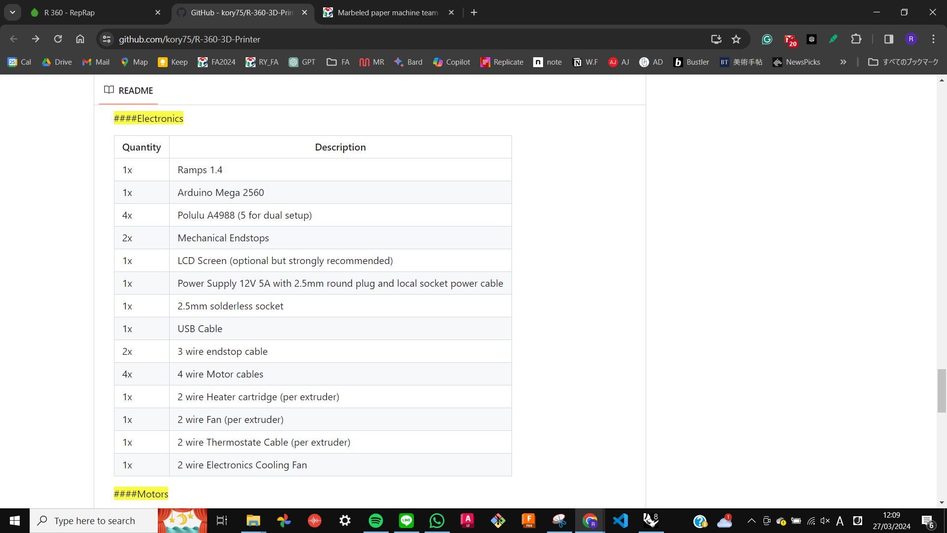
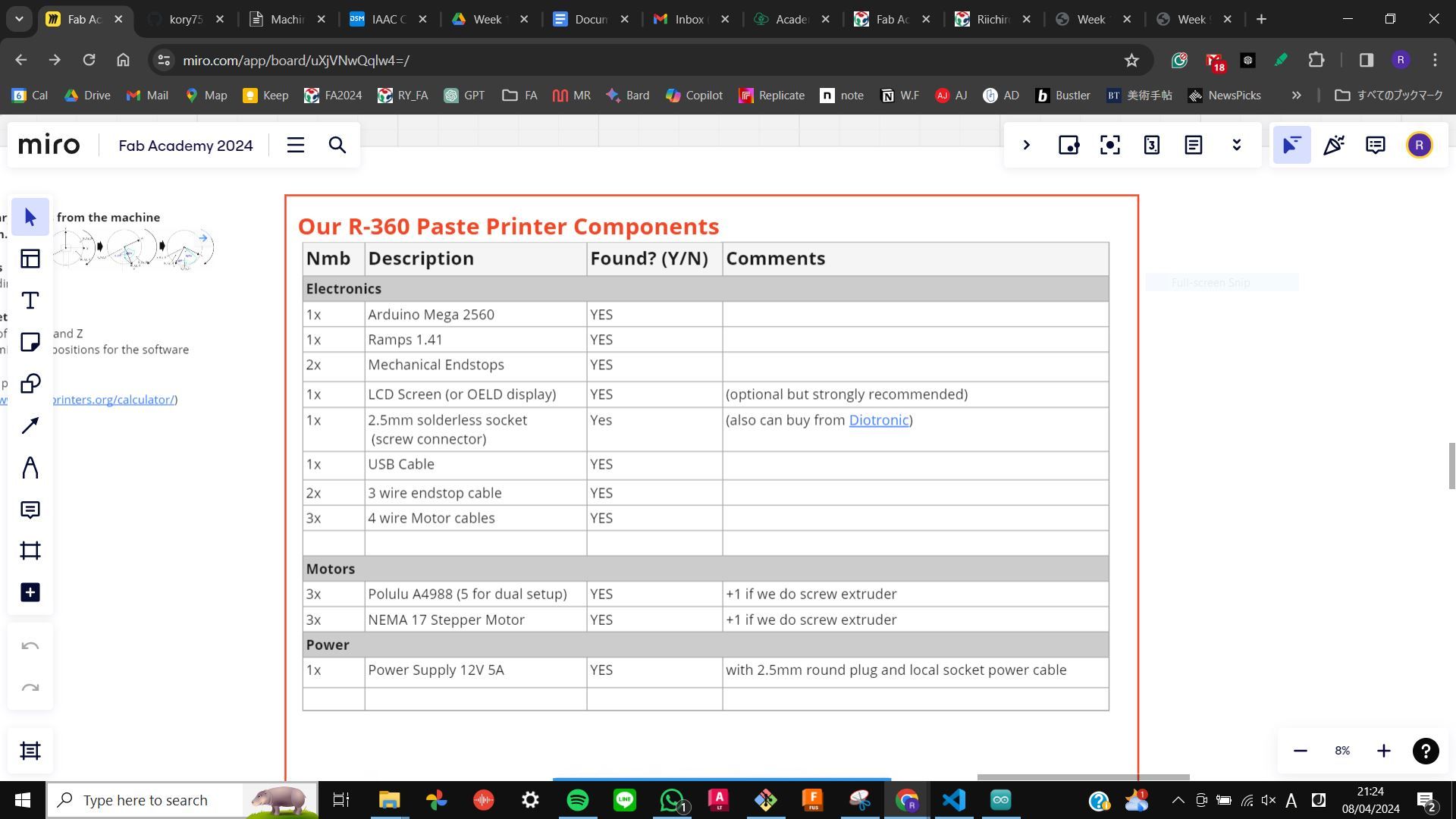
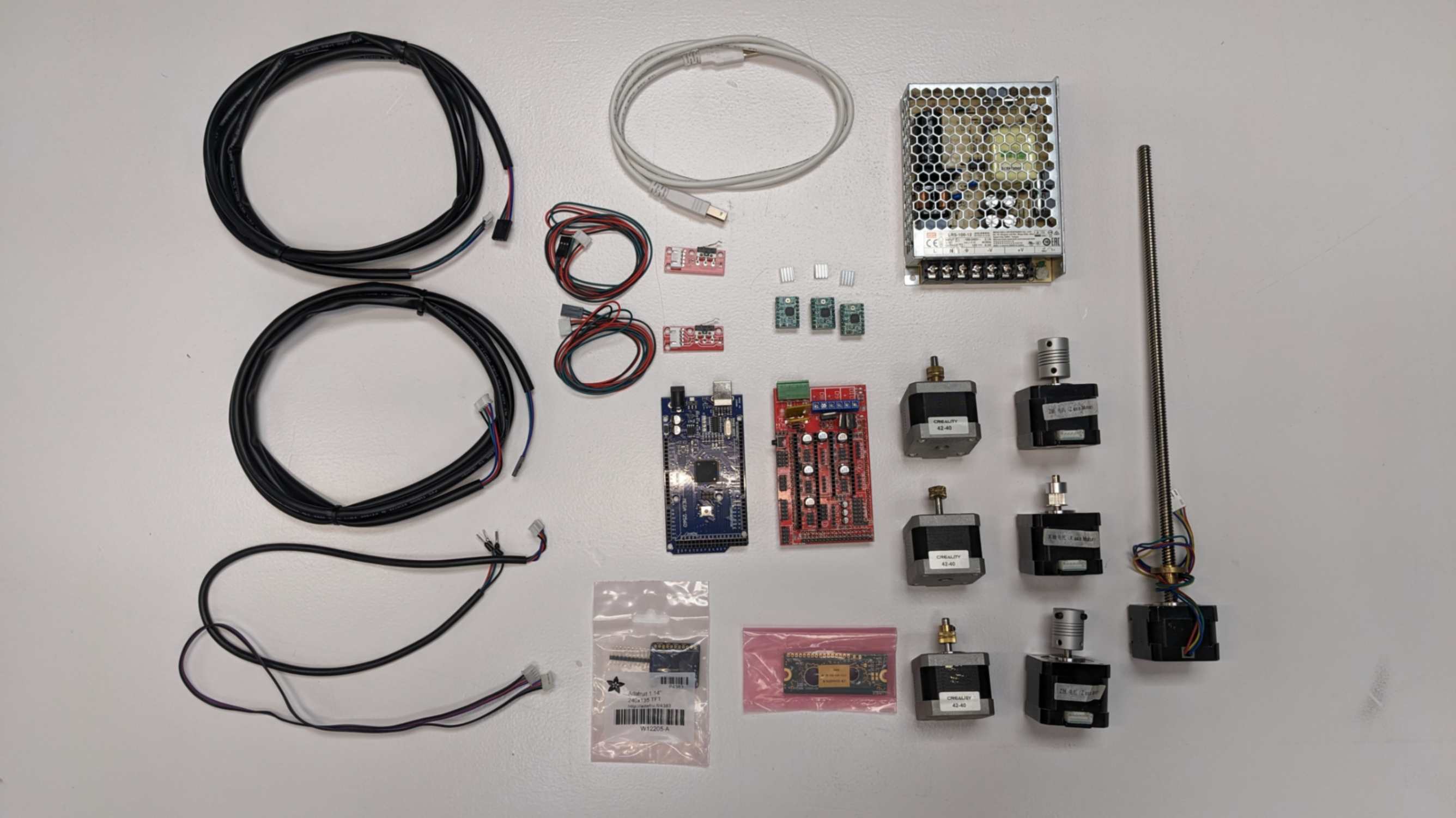
I was mainly in charge of the electronics and programming part. From the R360 3D Printer , I listed all the electronic components I needed for this printer. Since our printer is a paste printer, all the thermal components were not included.
Then, I started shopping for those components in our lab. By digging inside boxes full of electronics, looking into a bunch of shelves, and asking my tutor for help guiding me on where to look for components, I was lucky to have all the electronic components and did not need to buy anything.
Electronic Connection
To make the right connection in each component I followed the page about
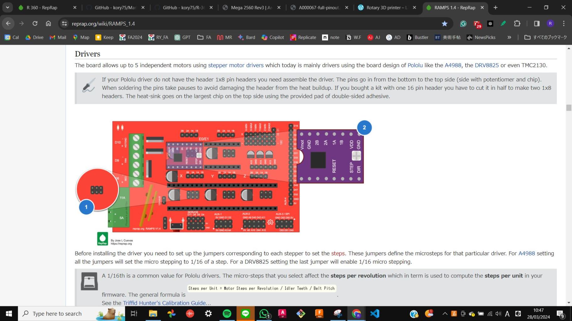
RAMPS 1.4 RepRap
Below I will explain each step by explaining photos.
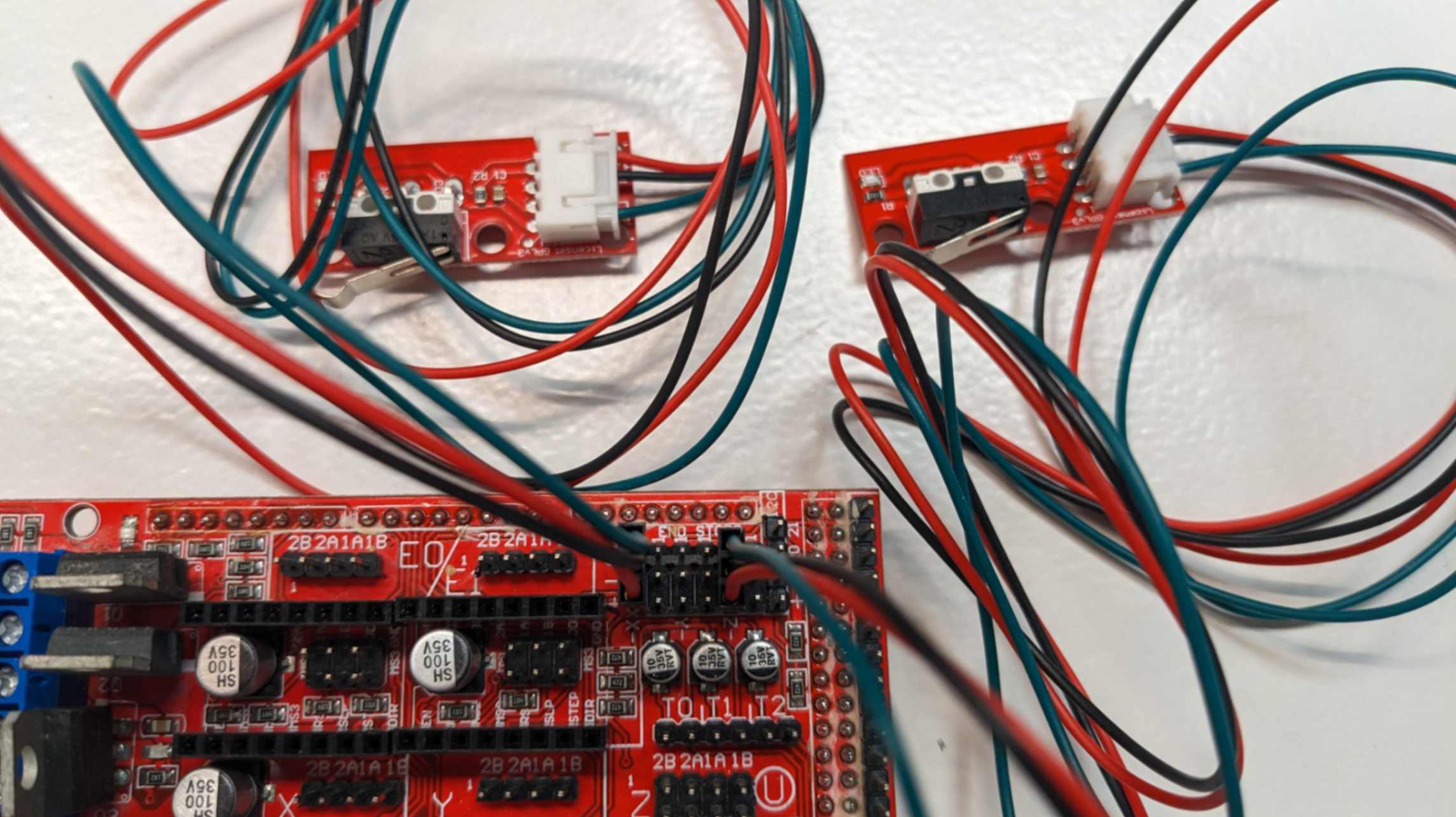
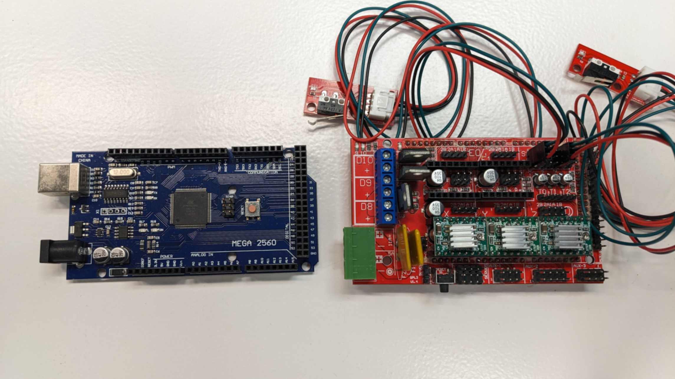
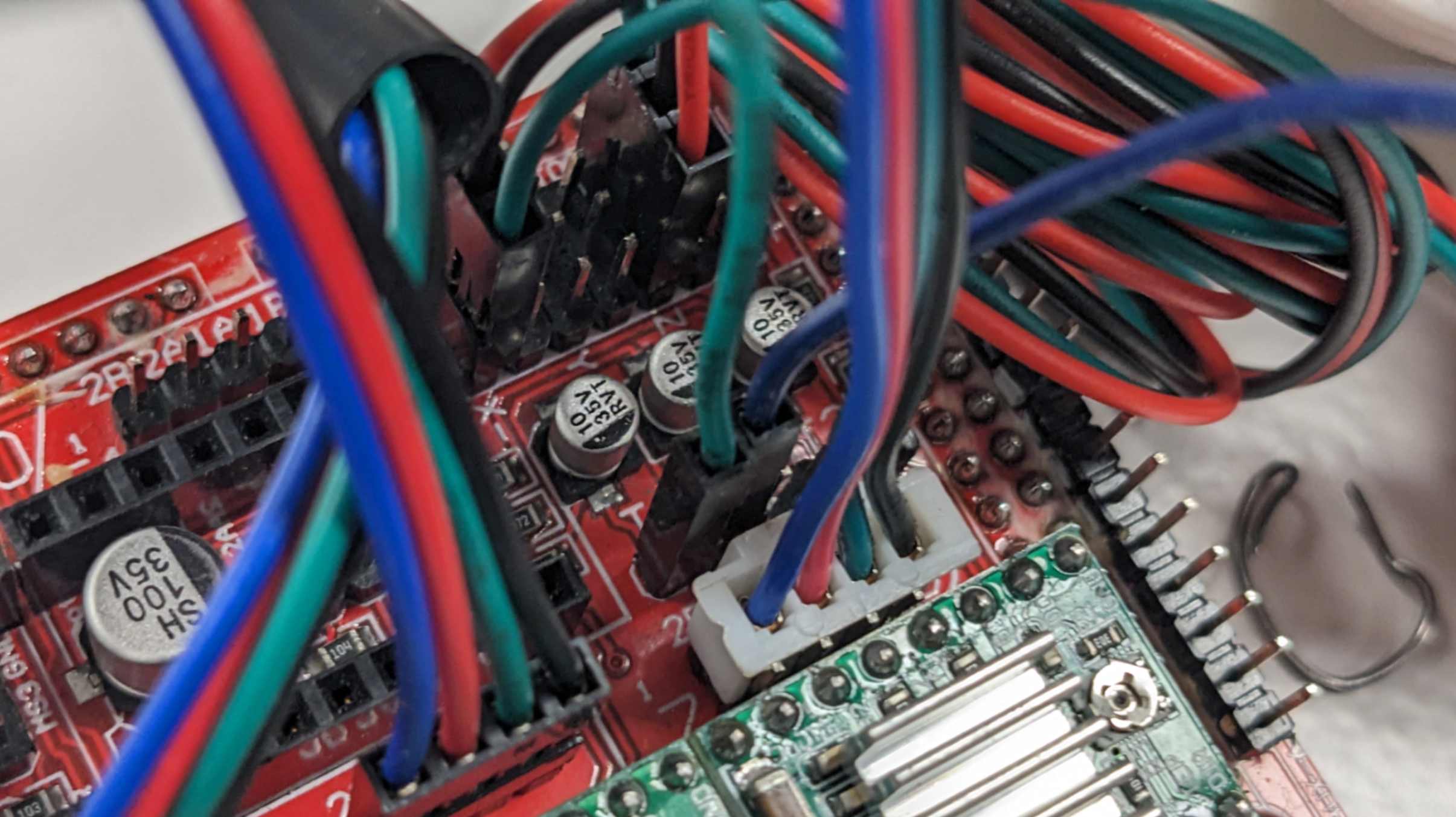
Connect end-stops in the right orientation to the end-stop pin on Ramps 1.4. There are 6 sets of pins (from left to right, X min, X max, Y min, Y max, Zmin, and Zmax).it is important to know which end-stop needs to be connected to which pins. For our printer, I only needed X min and Z min.
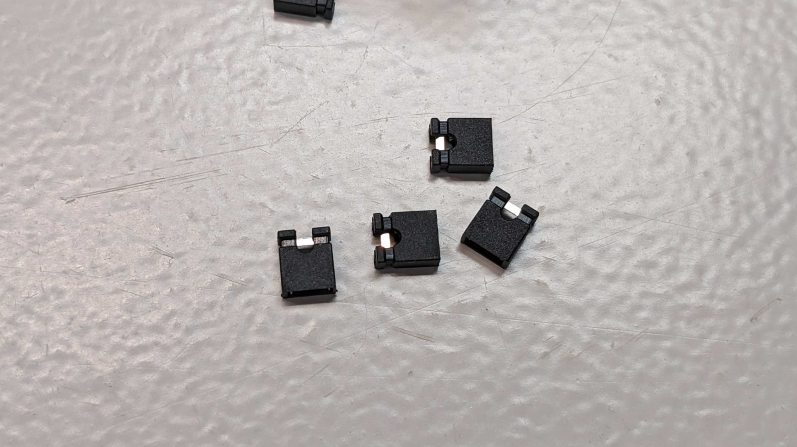
Before connecting the motor driver (A4988), jumper pins need to be inserted first because it is located underneath the motor driver. Connecting these pins allows micro-stepping.
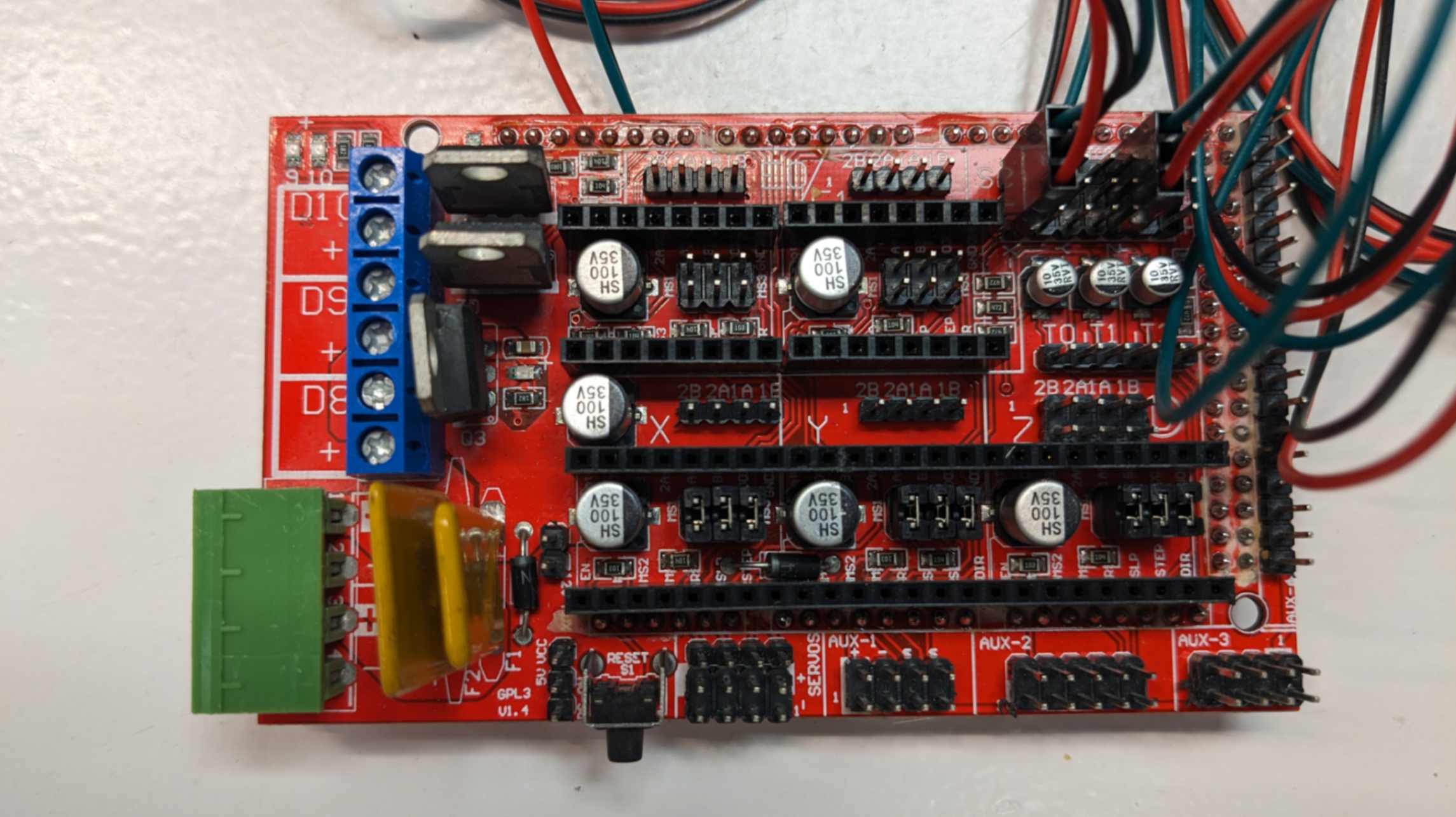
Place motor driver (A4988) for X Y Z. Make sure the orientation is right by aligning the GND pin. If there is a motor for extruder use E to connect an extra motor.
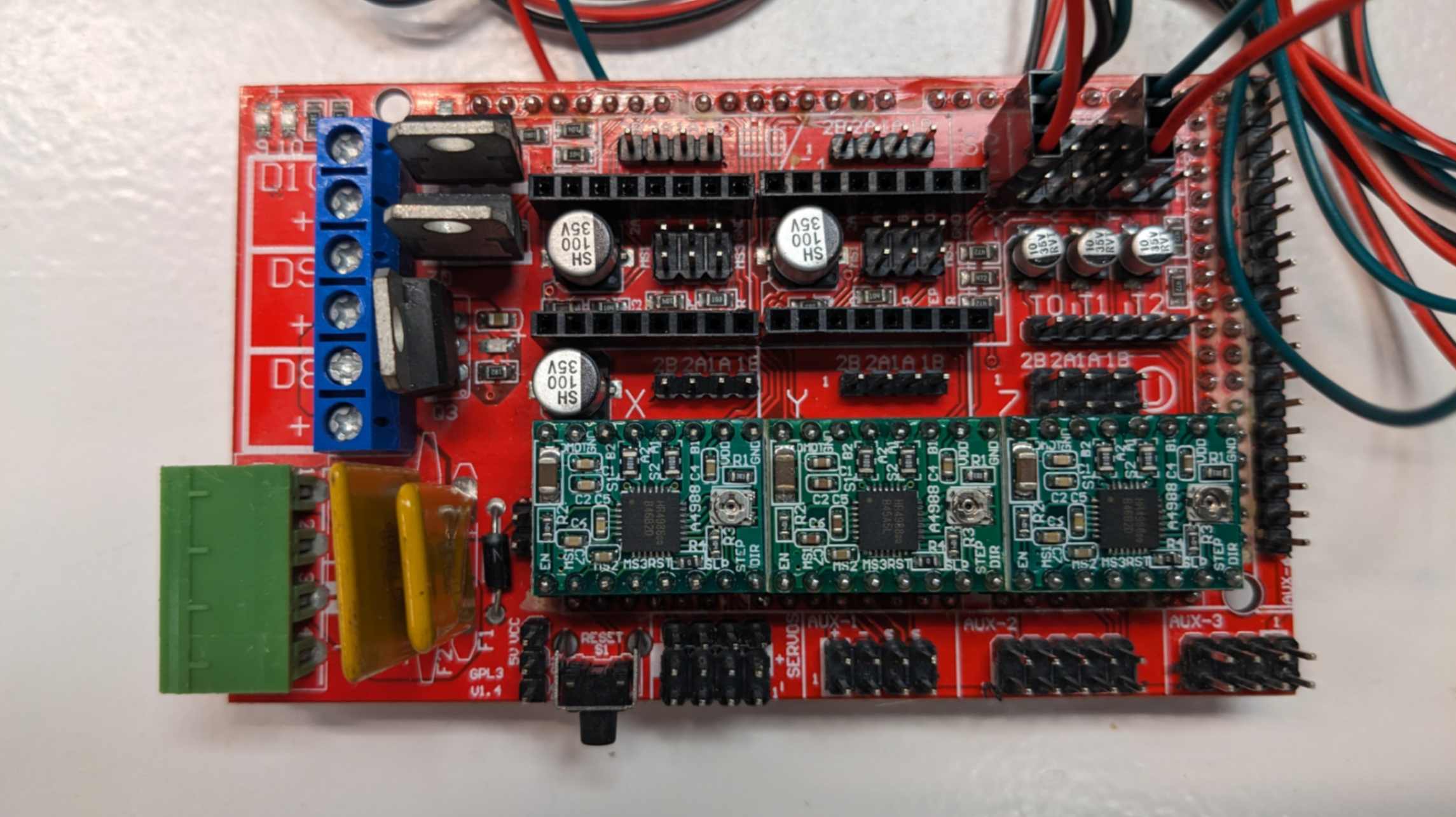
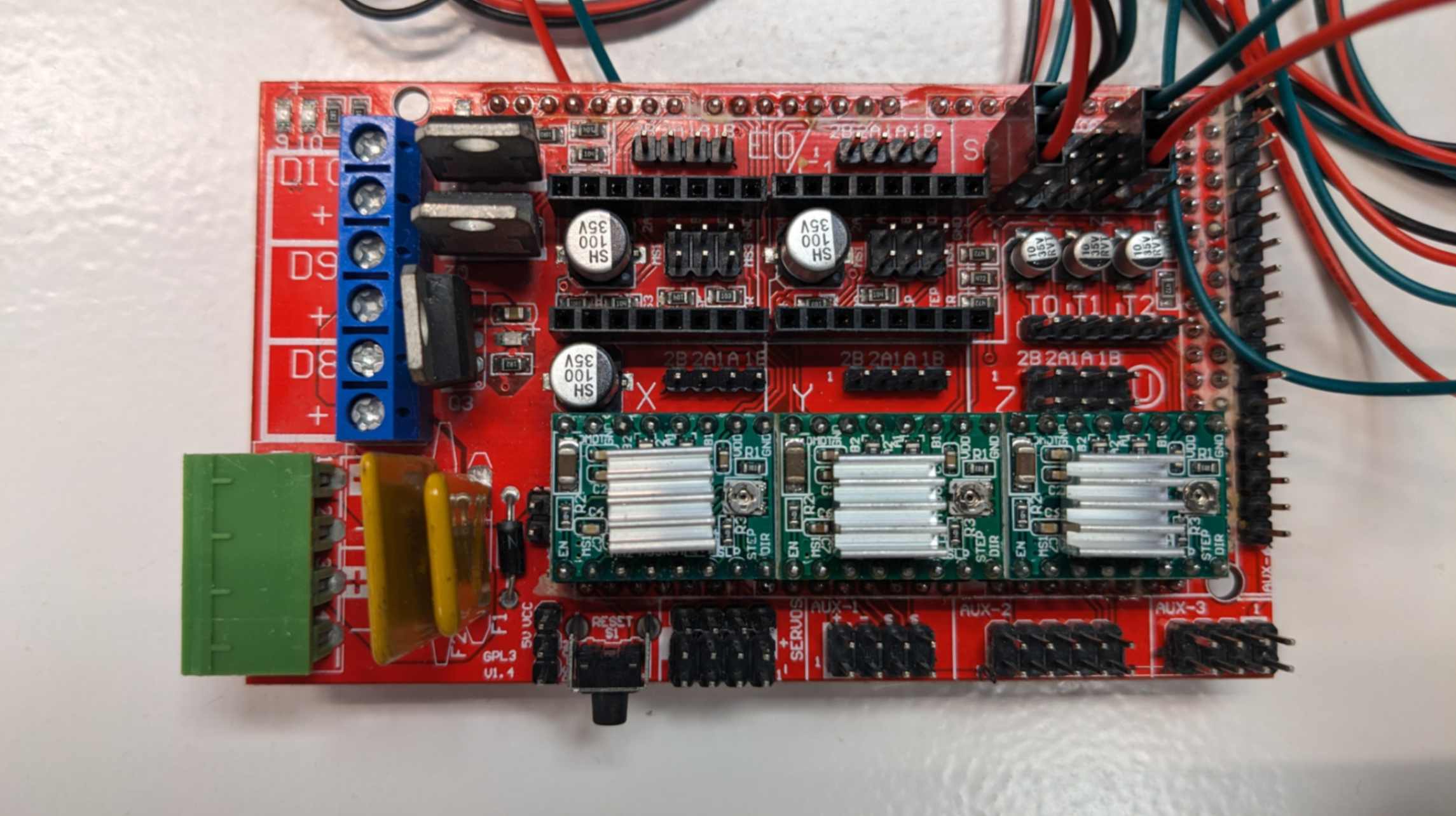
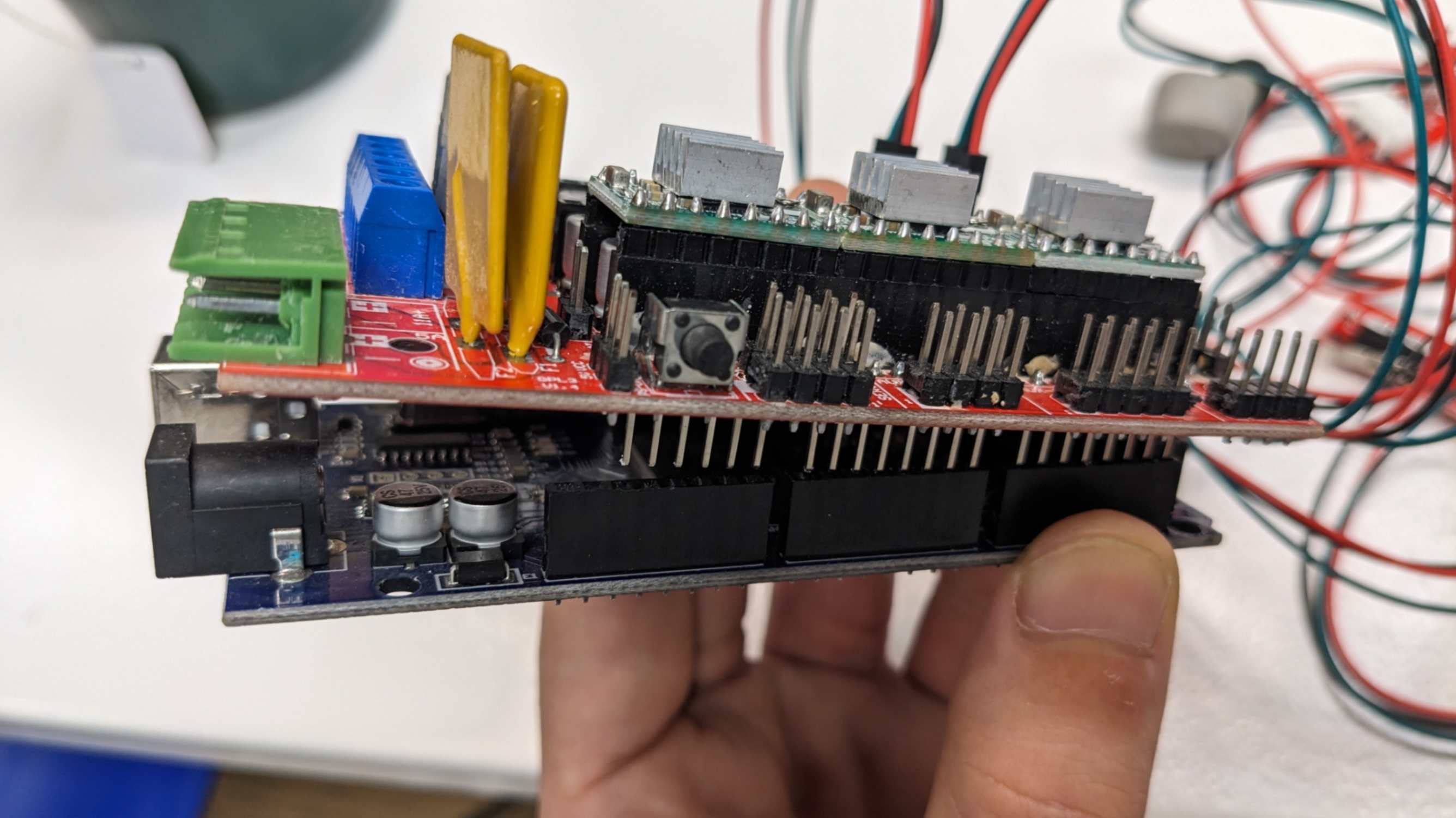
Stick the small silver components on top of the microcontroller of the motor driver. This is to release heat from the microcontroller. These components come with a motor driver package.
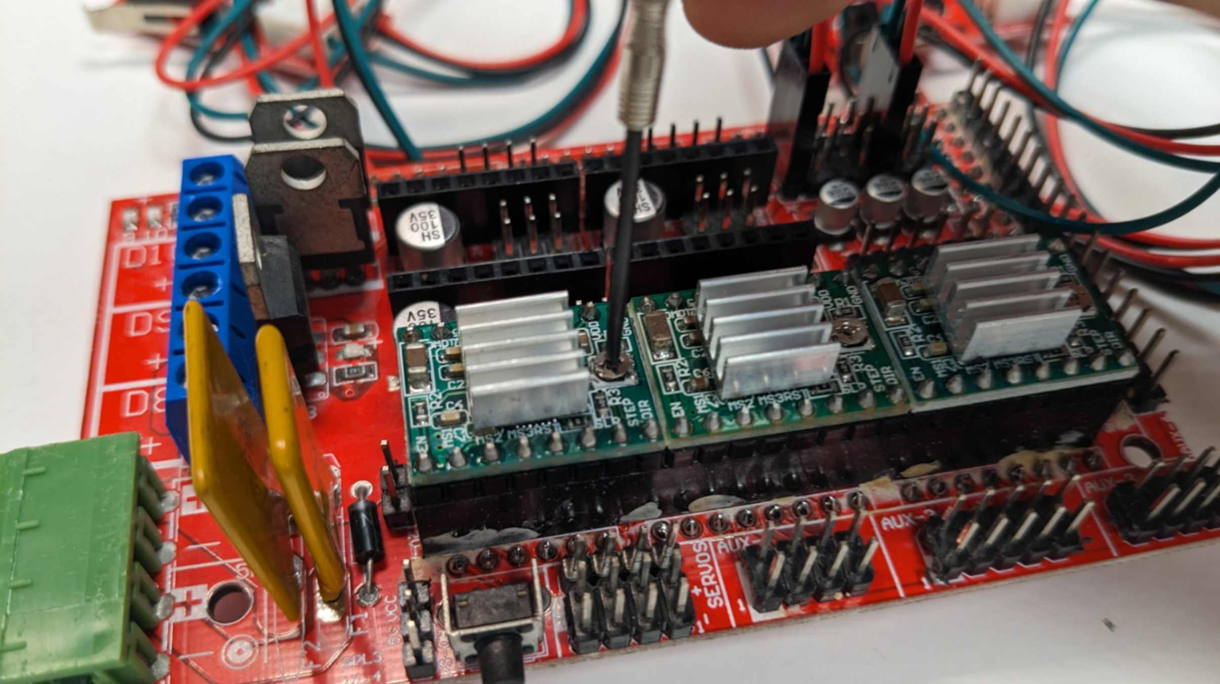
Twist the screw on the motor driver, counterclockwise and then twist clockwise for 25%. This is to make sure not too much current will go through the motor driver.
Place the Ramps1.4 on top of the Arduino Mega 2560. Male pins of Ramps1.4 and Female pins of Arduino Mega 2560 should align.
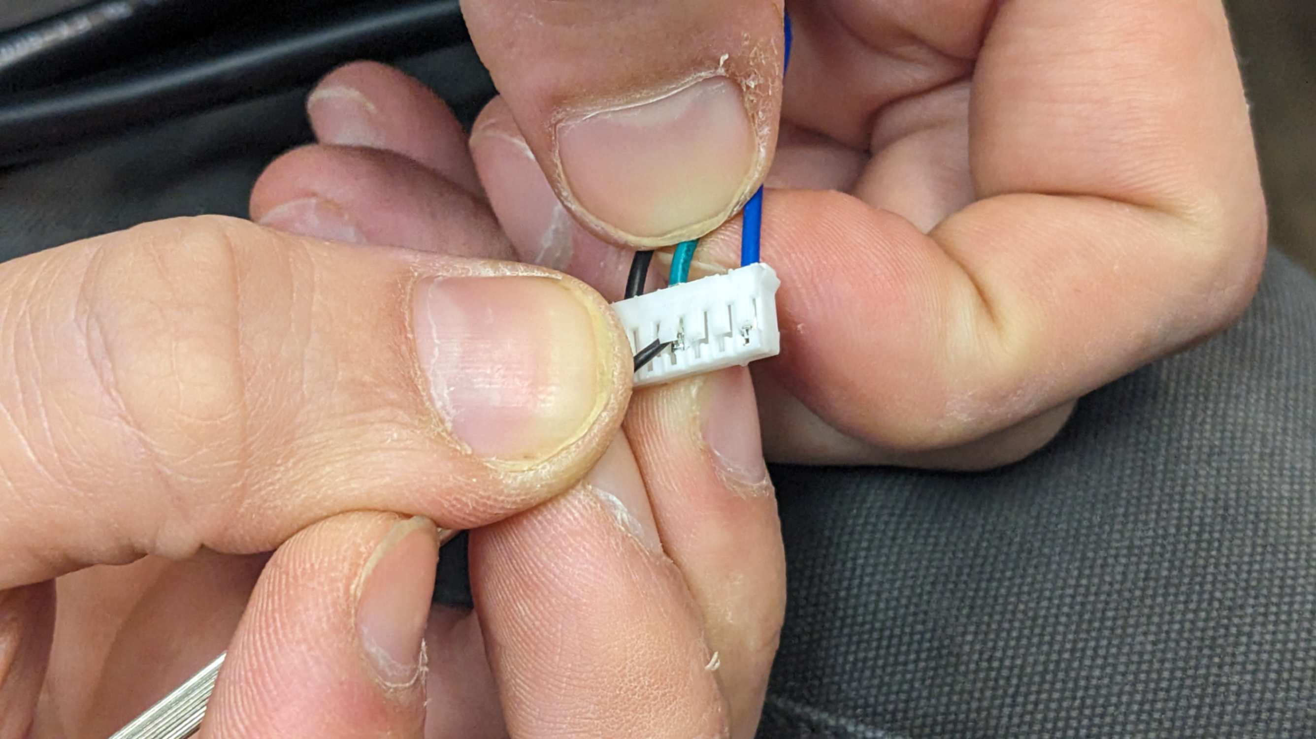
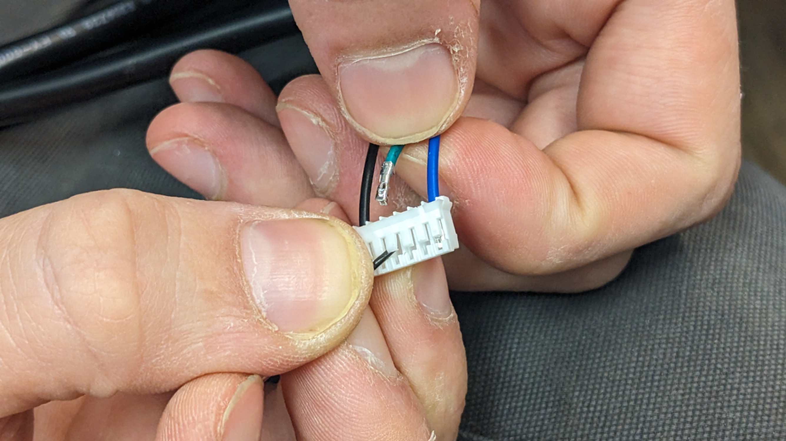
Check the phases of stepper motors. The trick is to use a wire and connect to 6 pins that come out from the motor one by one while twisting the shaft. When the shaft becomes harder to twist, the connection is a phase. By the way, there are 6 pins but you only use 1 pin on each side and 2 pins in the middle. In our case, it was cross phase so we needed to rearrange the wiring.
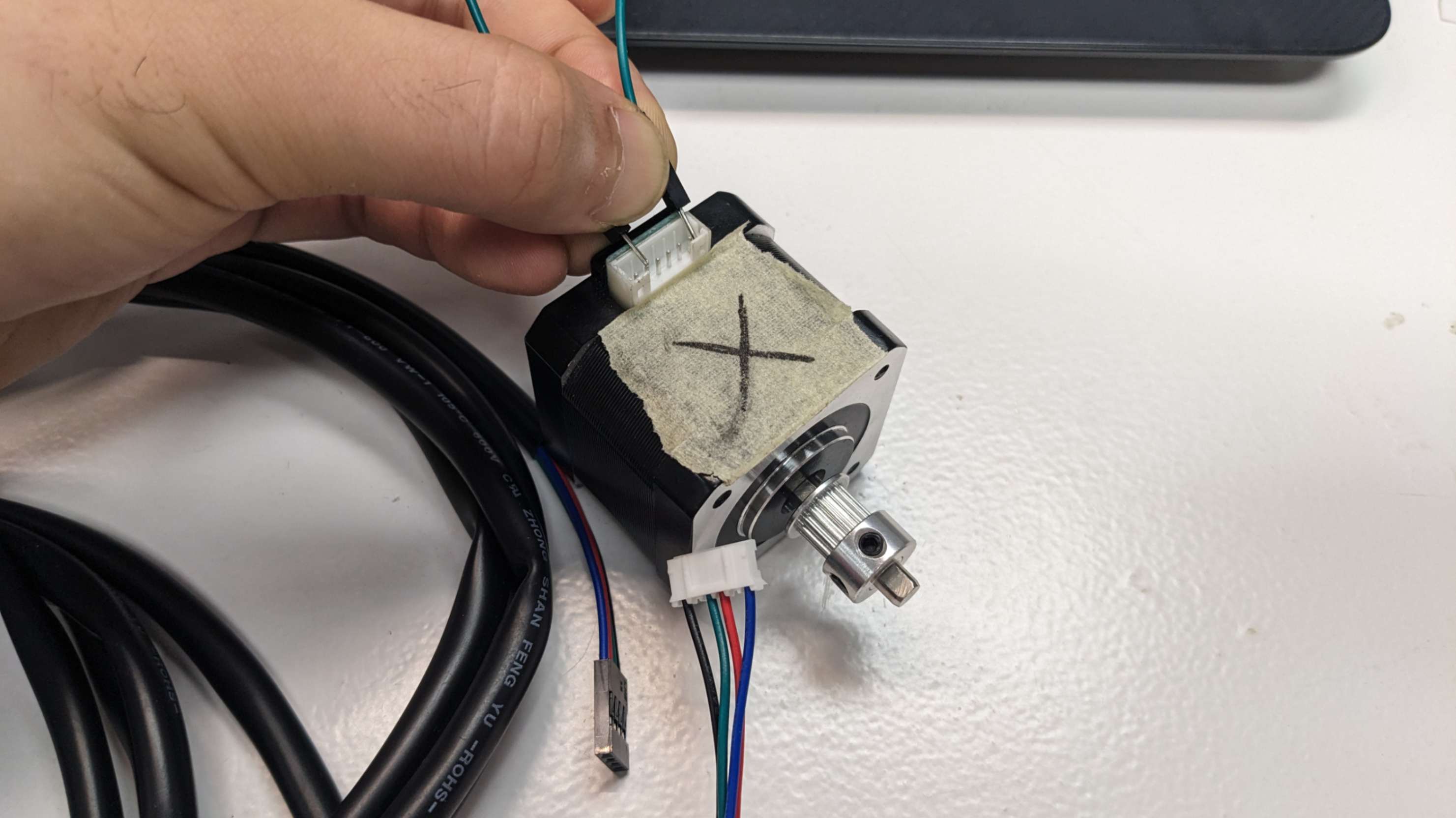
Rearrange the wiring if necessary. In our case, it was a cross phase, and Black & Green, Blue & Red were the phases which were defined by the data sheet of the motor. So we simply unplugged and relocated the wires.
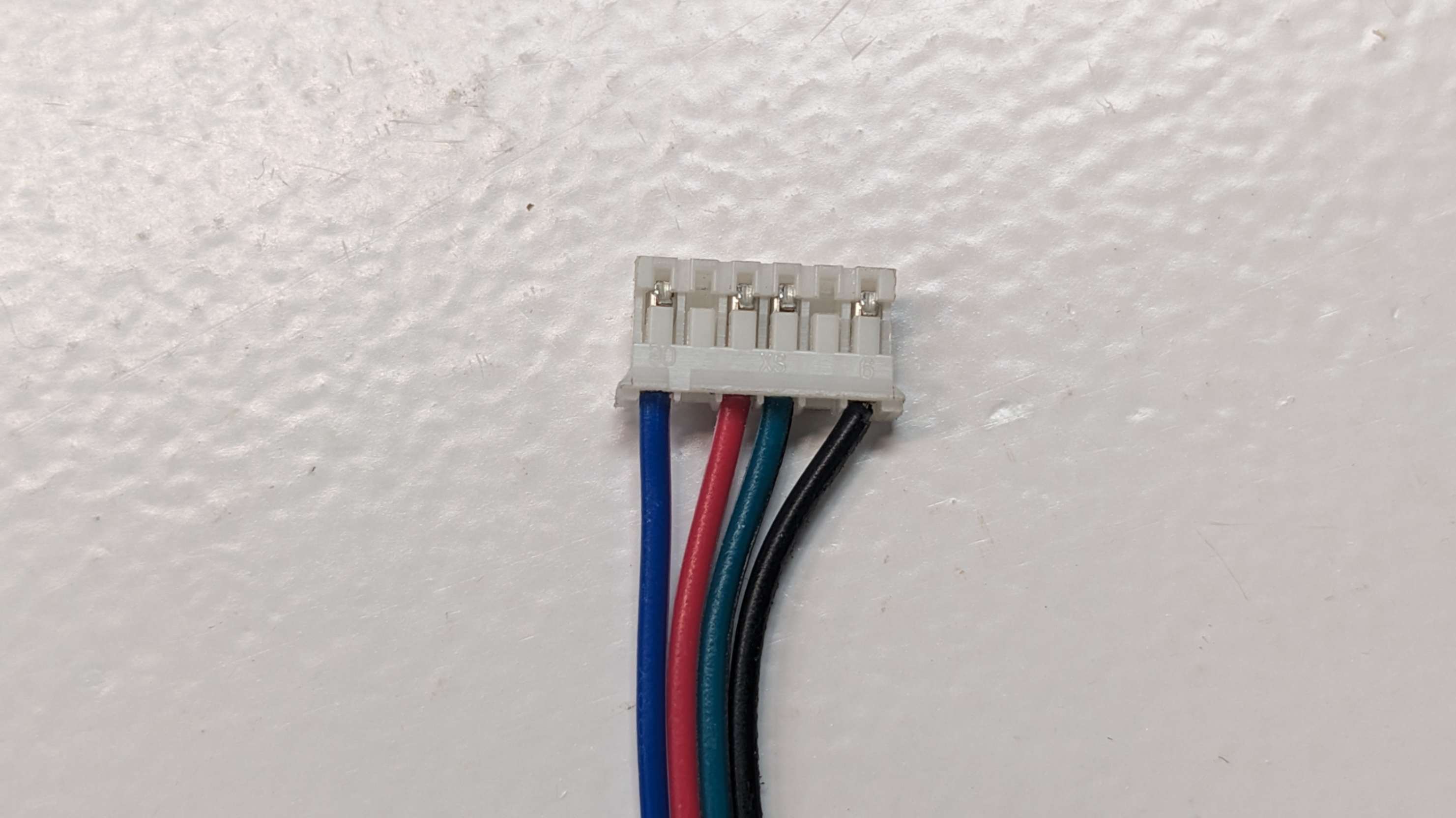
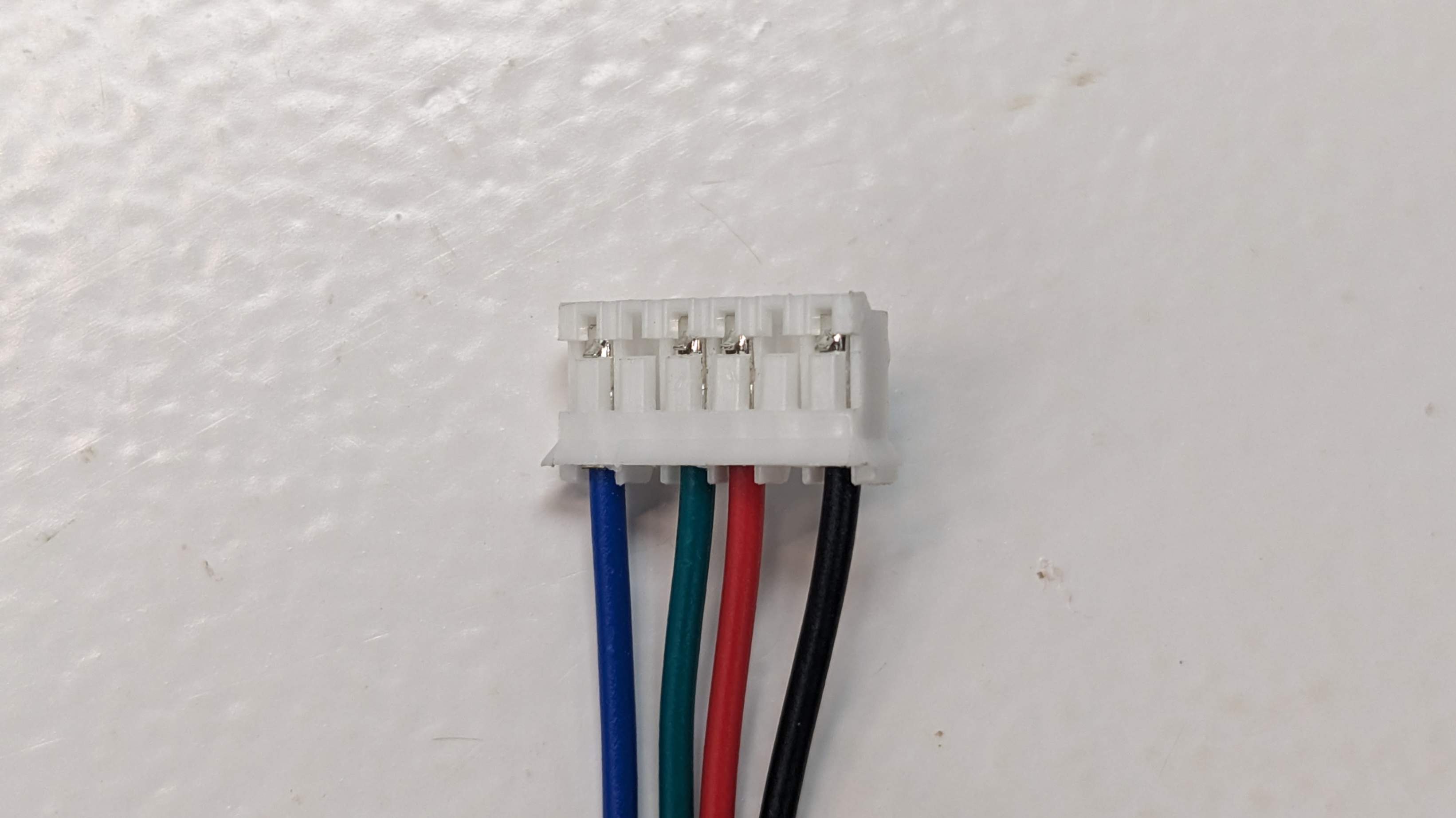
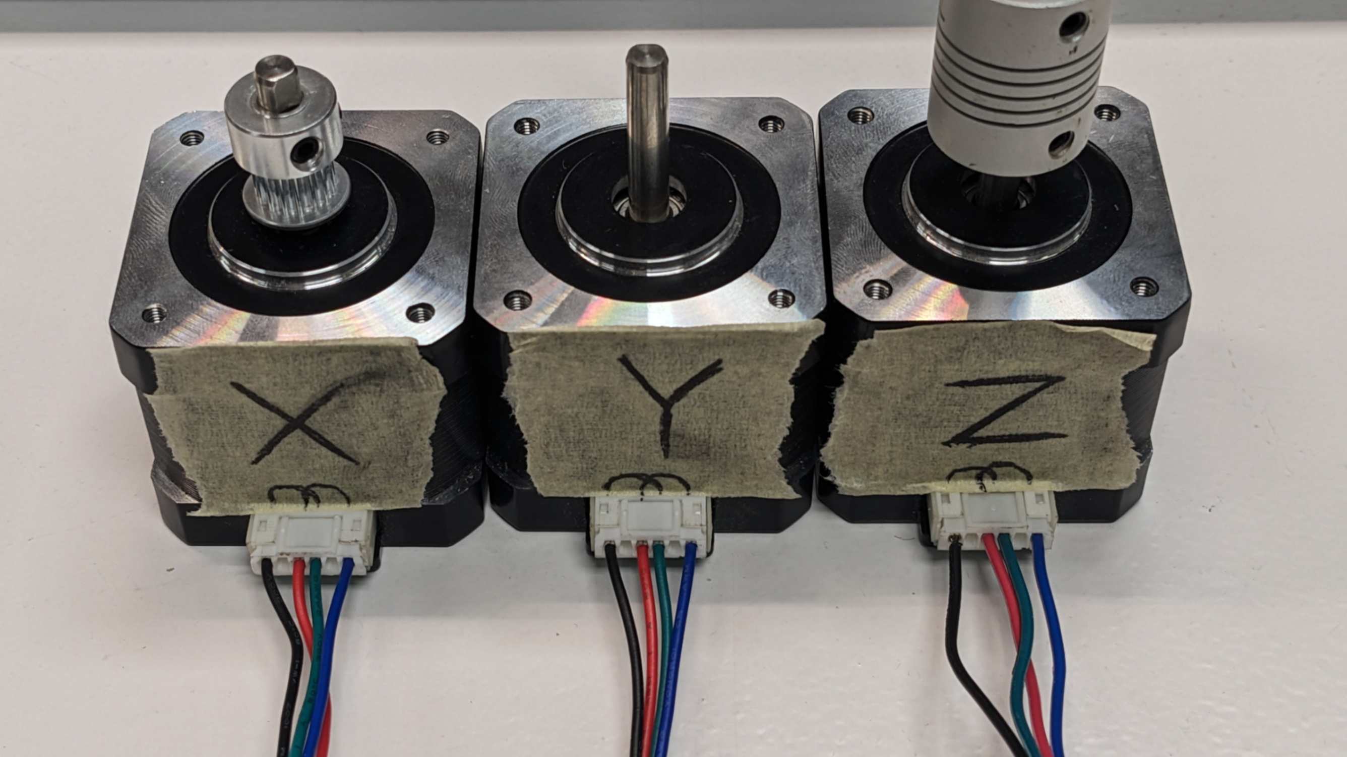
Plug the wires into the motors.
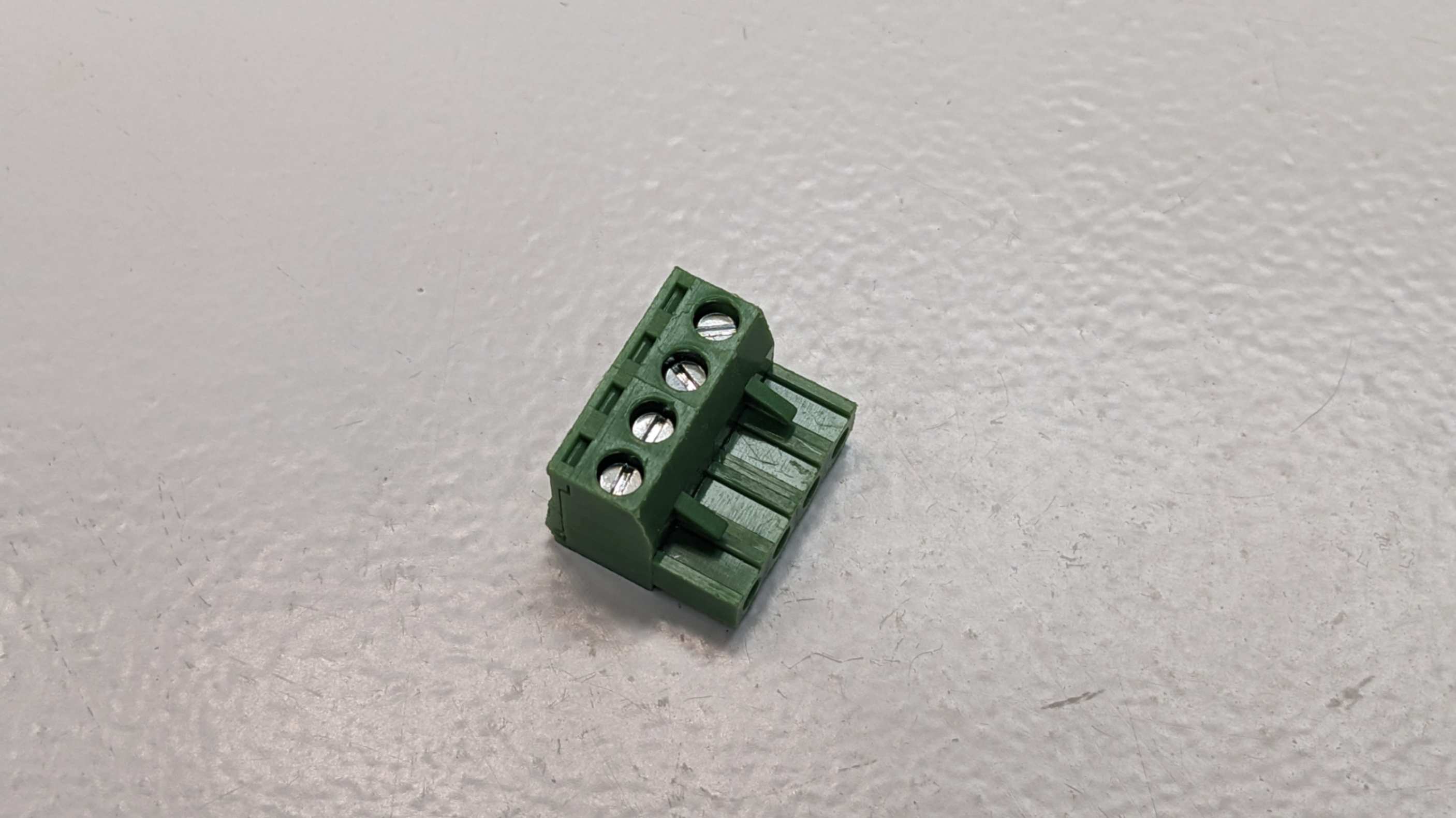
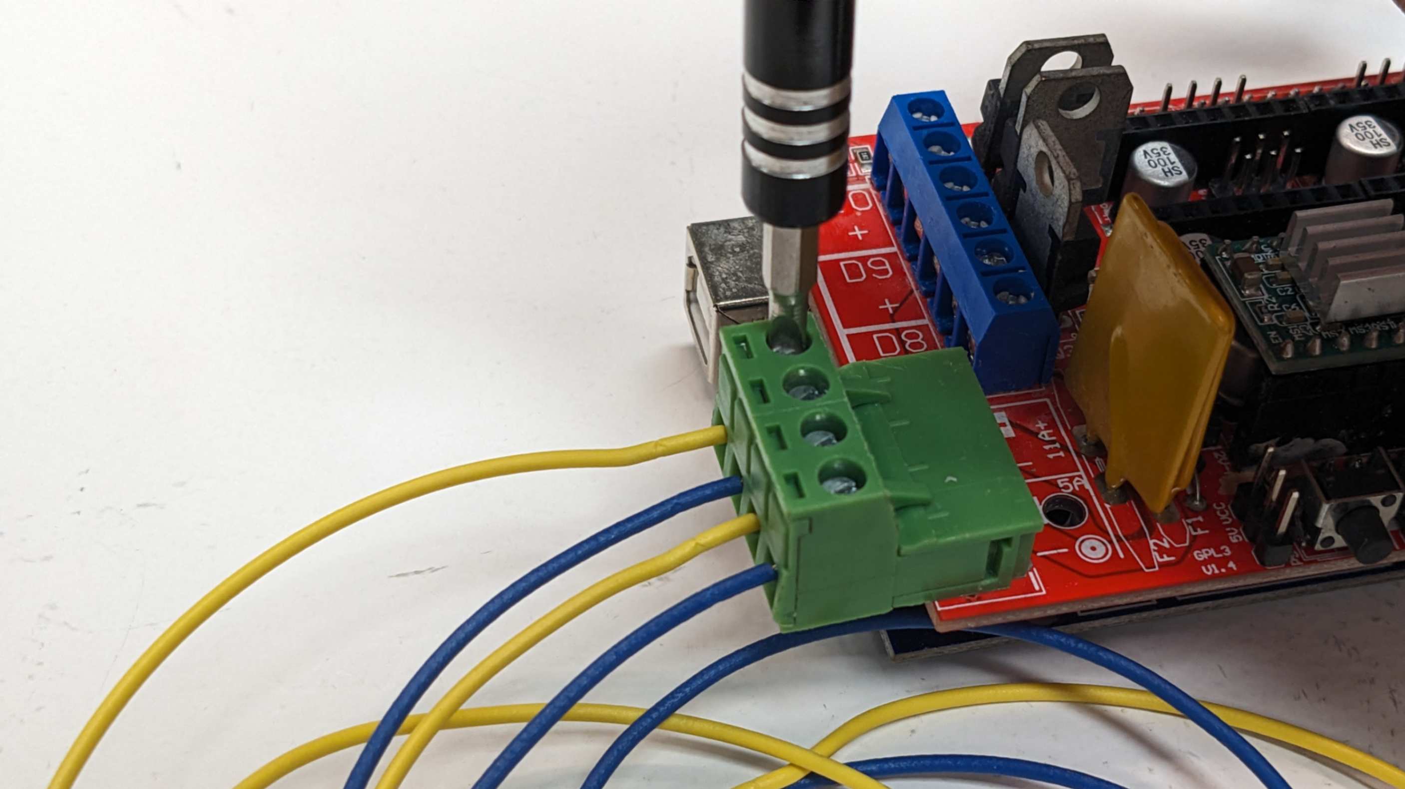
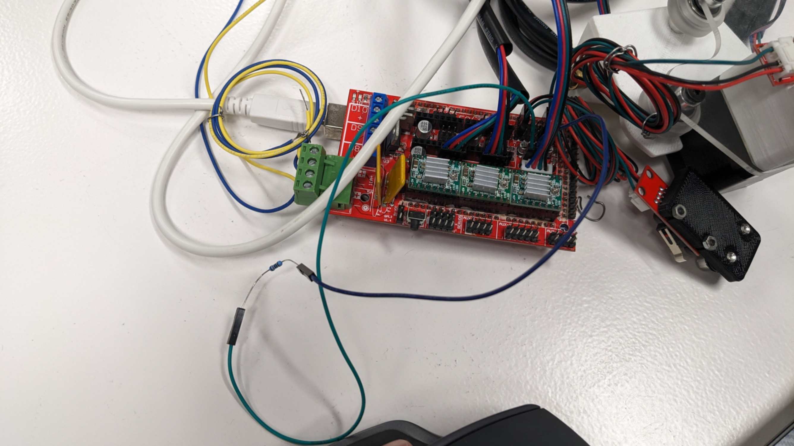
Plug a screw connector. In our case, we only needed 2 ports since the other 2 ports are for thermal components.
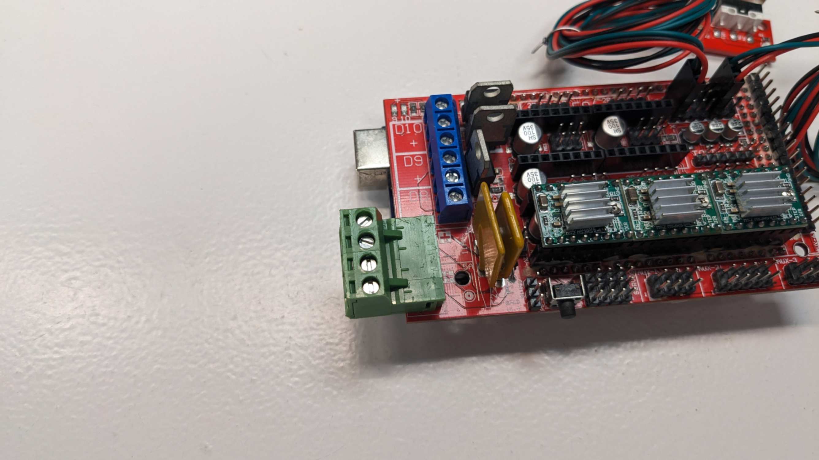
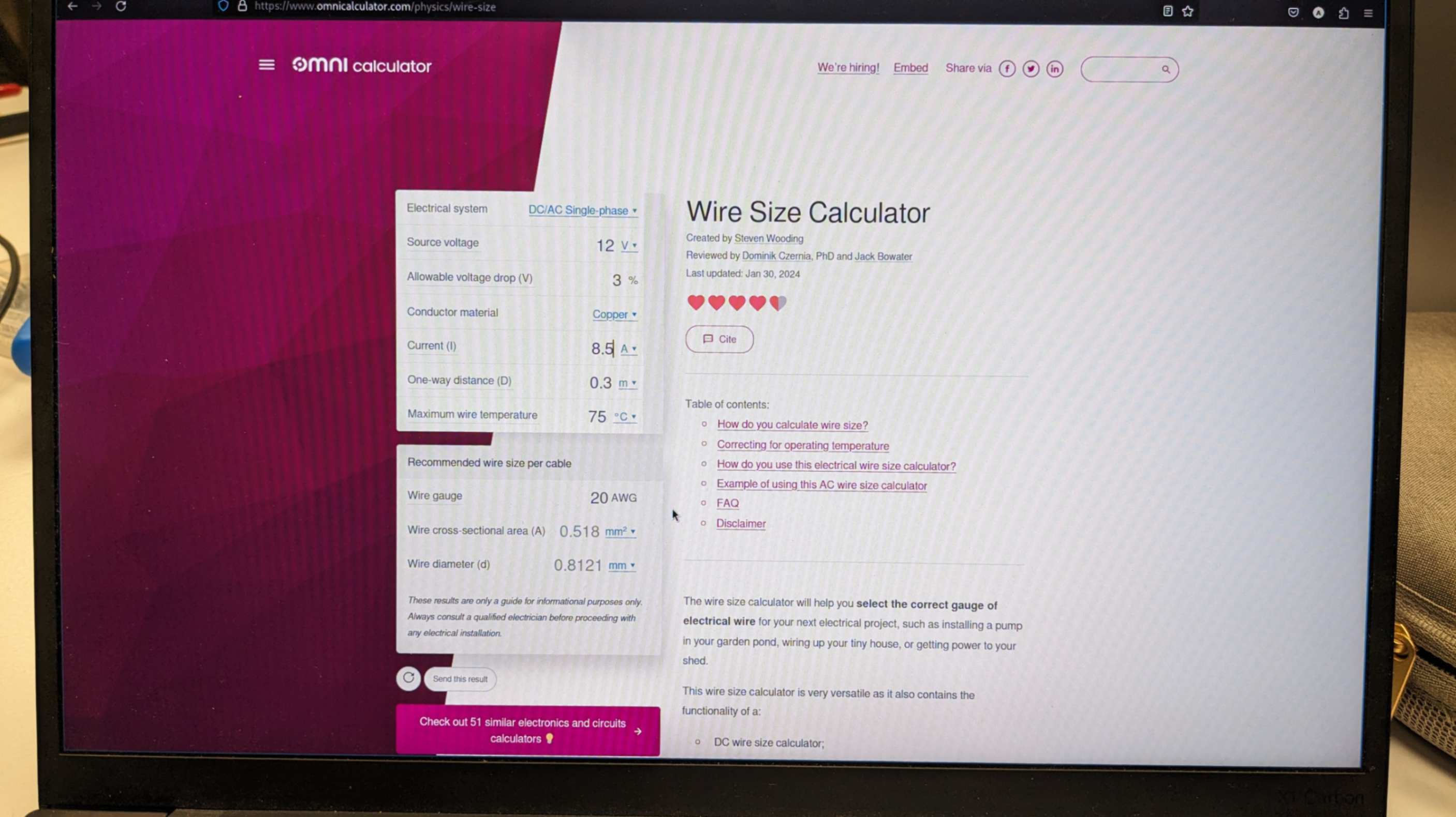
Calculate wire size using a wire size calculator In our case we have 22 AWG wires which we replaced with even thicker wires just to be safe.
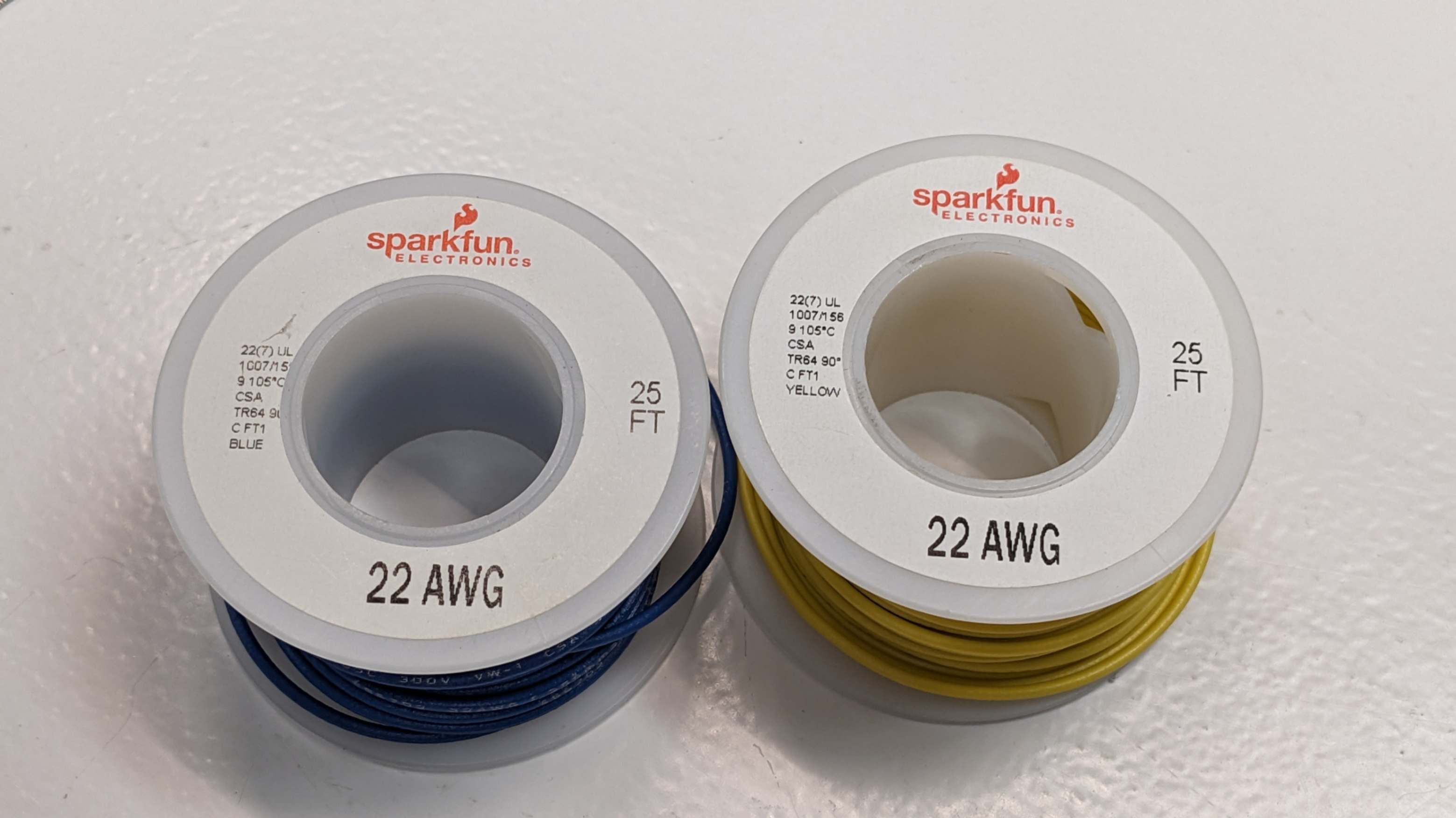
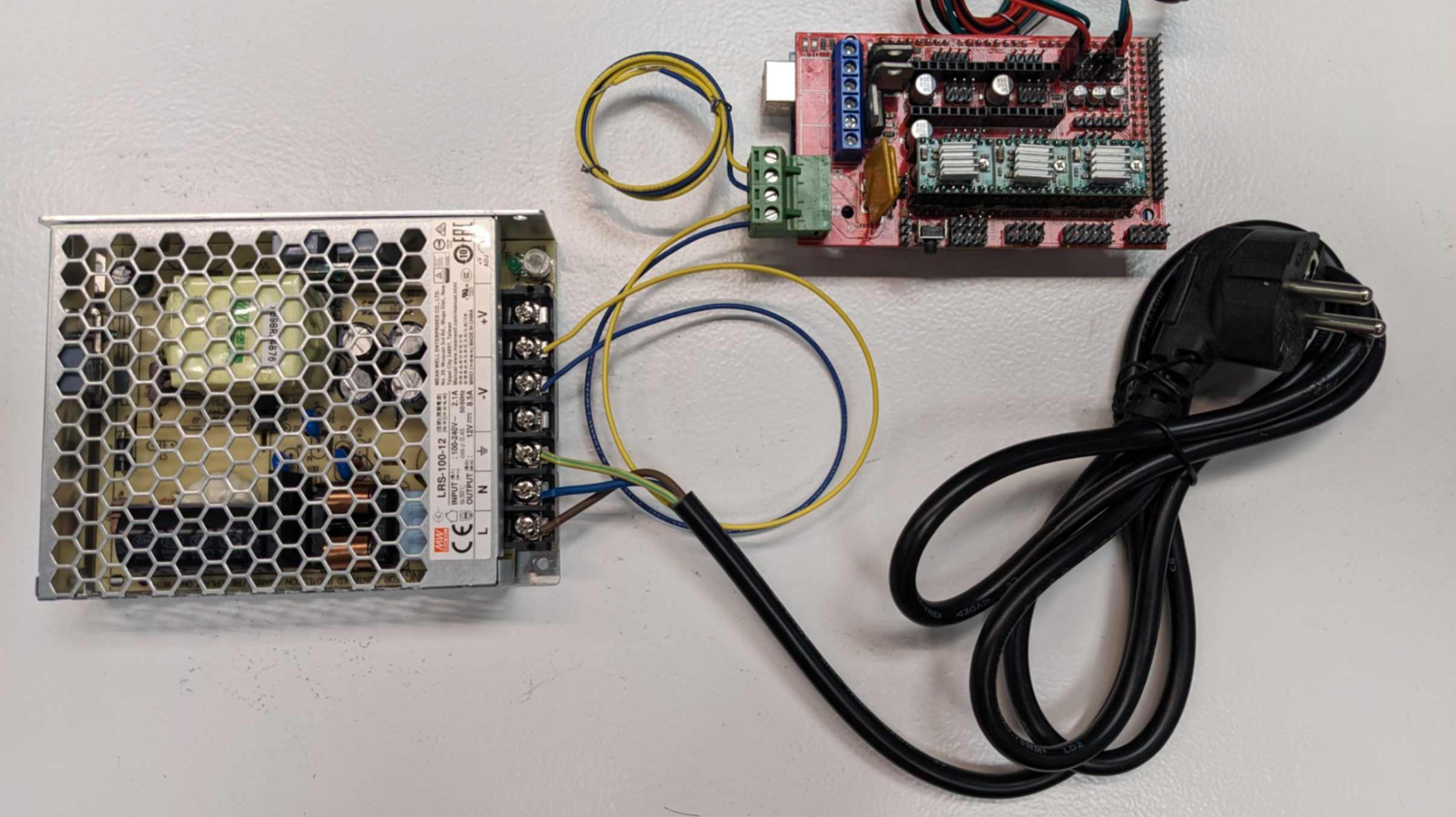
Connect +V and -V on the power supply and screw connectors with 22 AWG wires.
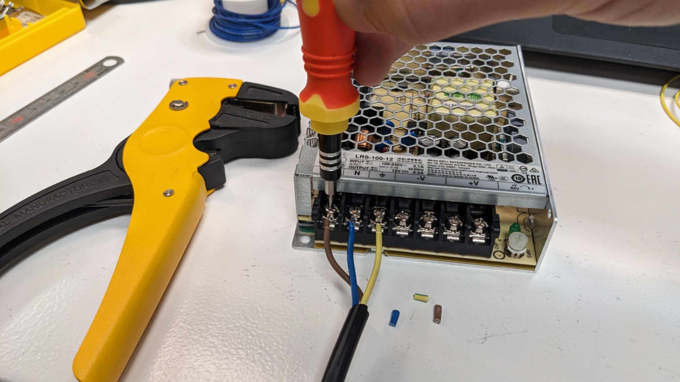
Connect L (Live), N (Neutral), and GND (Earth) on the power supply to AC lines.
Additional Connection
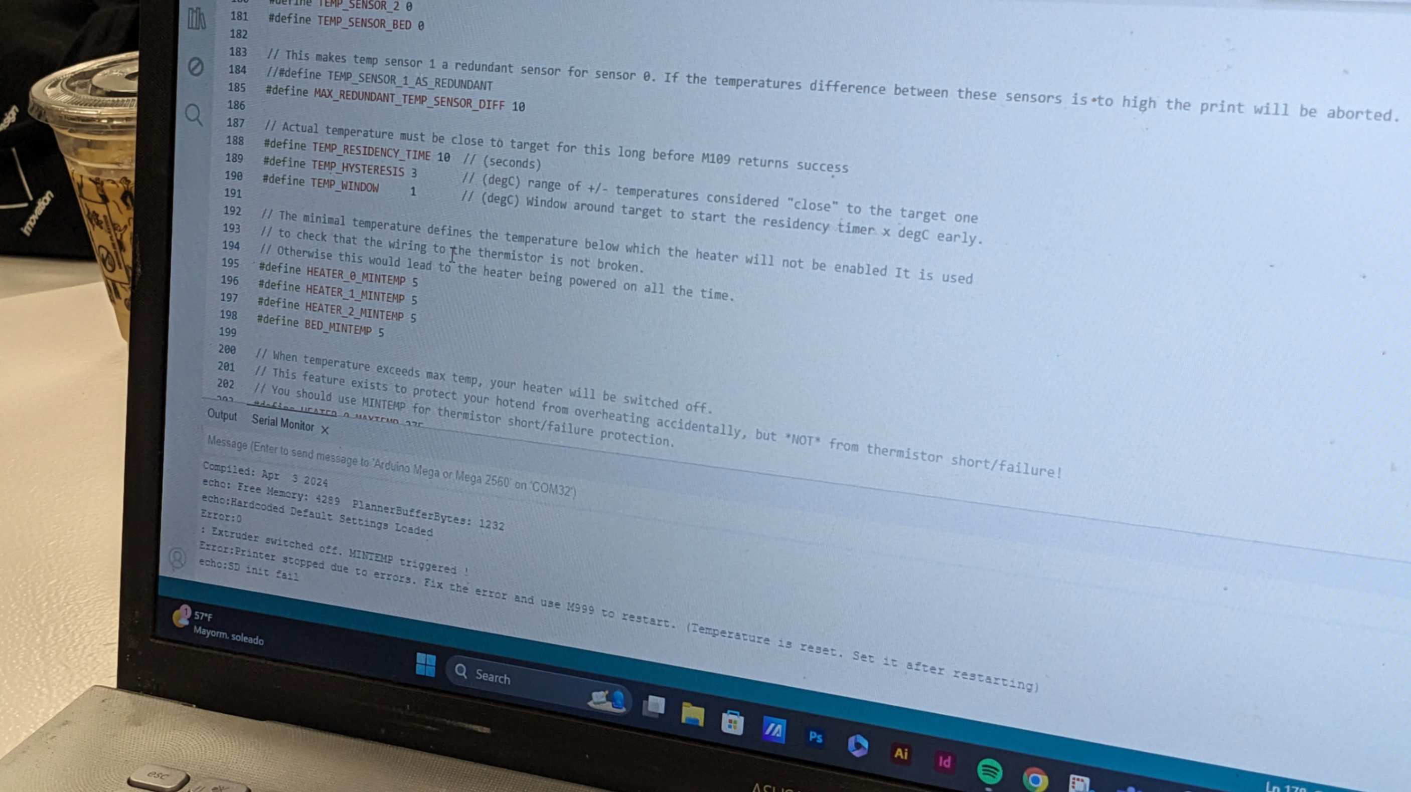
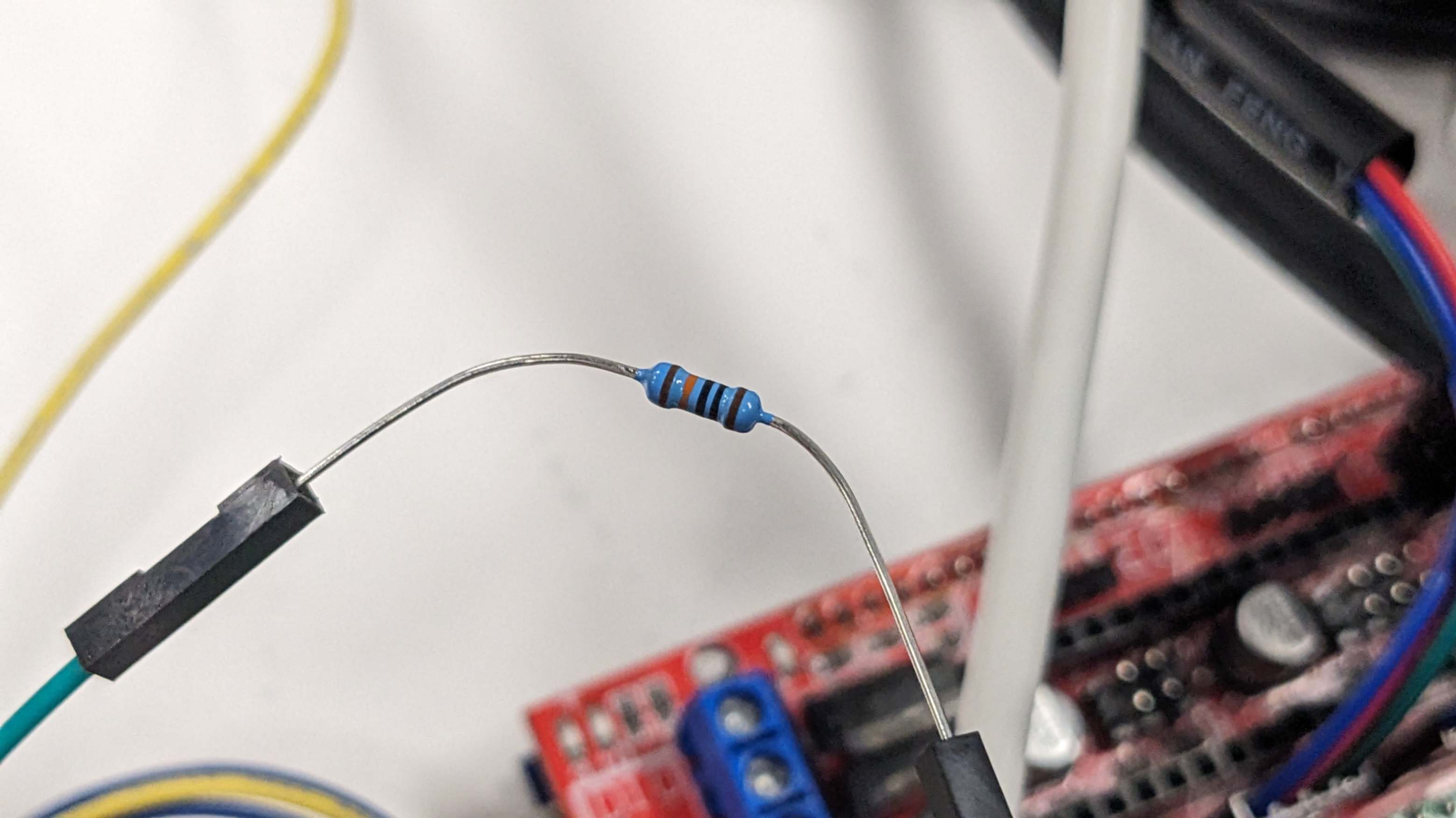
100k register was connected to T0 pins on Ramps1.4 because later we discovered an error shown in Arduino which was due to the missing connection of extruder temperature. So we added a register just to give it something to read.
Additional Adjustment
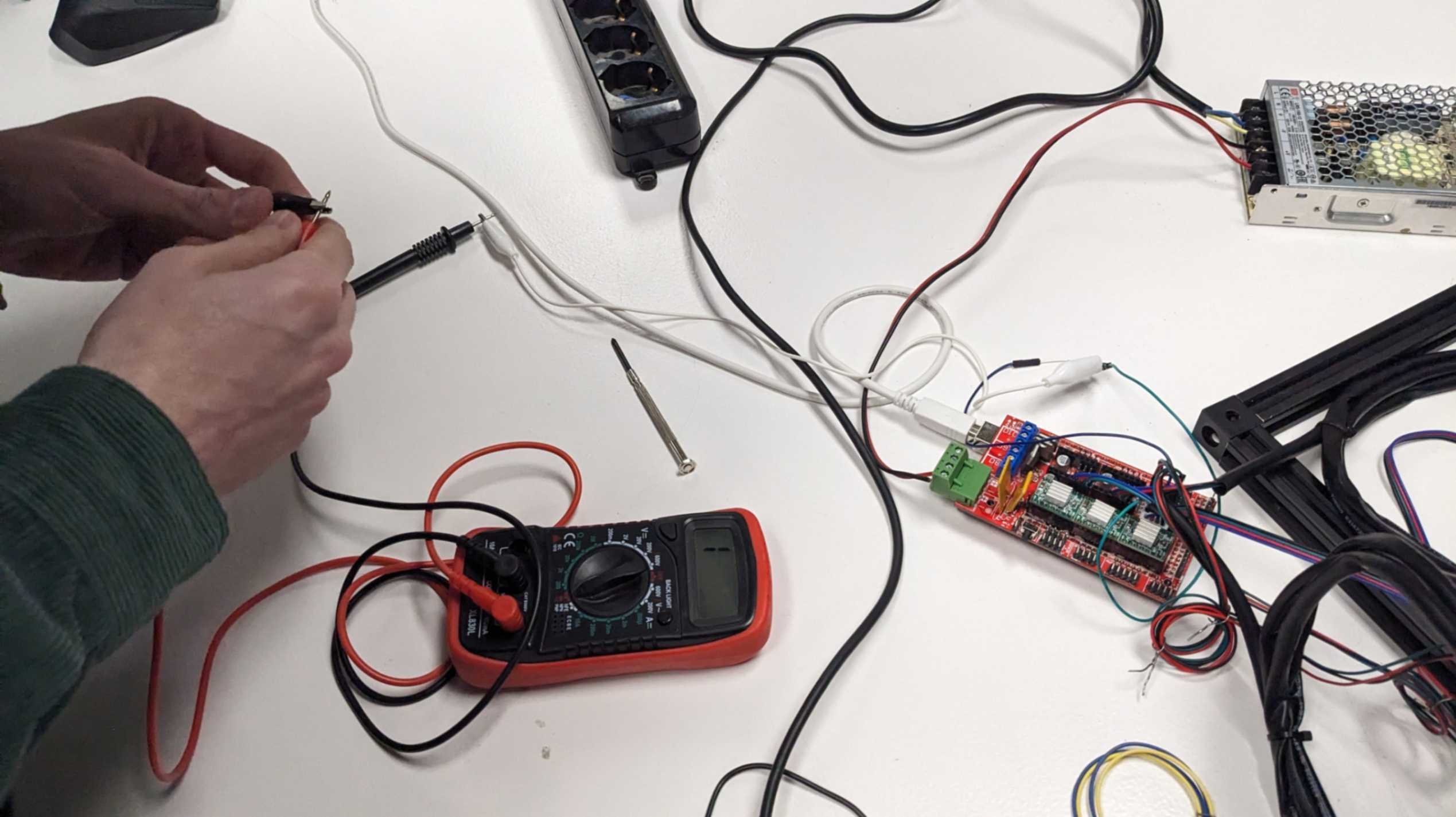
After we mount the motors on our printer we adjusted the Vref by twisting the screw on the motor driver while checking the current with a multimeter (use 2V setting). The value is calculated by this equation. Vref = I x 8 x Rsense. Details are explained on this page. In our case, the value was 0.64, so we set all the motor drivers to this value. Ideally, use a non-conductive tool to do this step.
Other Contribution
Apart from Electronics I was also involved in programing and firmware part with Andrea. The documentation for that is documented by her in group page. Also I volunteered to do scheduling and spliting tasks for the group. Of course I was involved in assembly of the machine which all of the team worked togather.