Week 9
Output Device
Fab Academy 2024
Riichiro Yamamoto
Dear My Friend
This week I was introduced to OOutput devices such as Motors, LED lights, Speaker, etc. I am excited about this week because I am finally controlling something physical by programming magic. Also, I was able to pray with programming a little bit more than blinking an LED light, so I am looking forward to testing a lot of output devices especially something that creates movement.
Hope you enjoy
Riichiro Yamamoto
Group Assignment
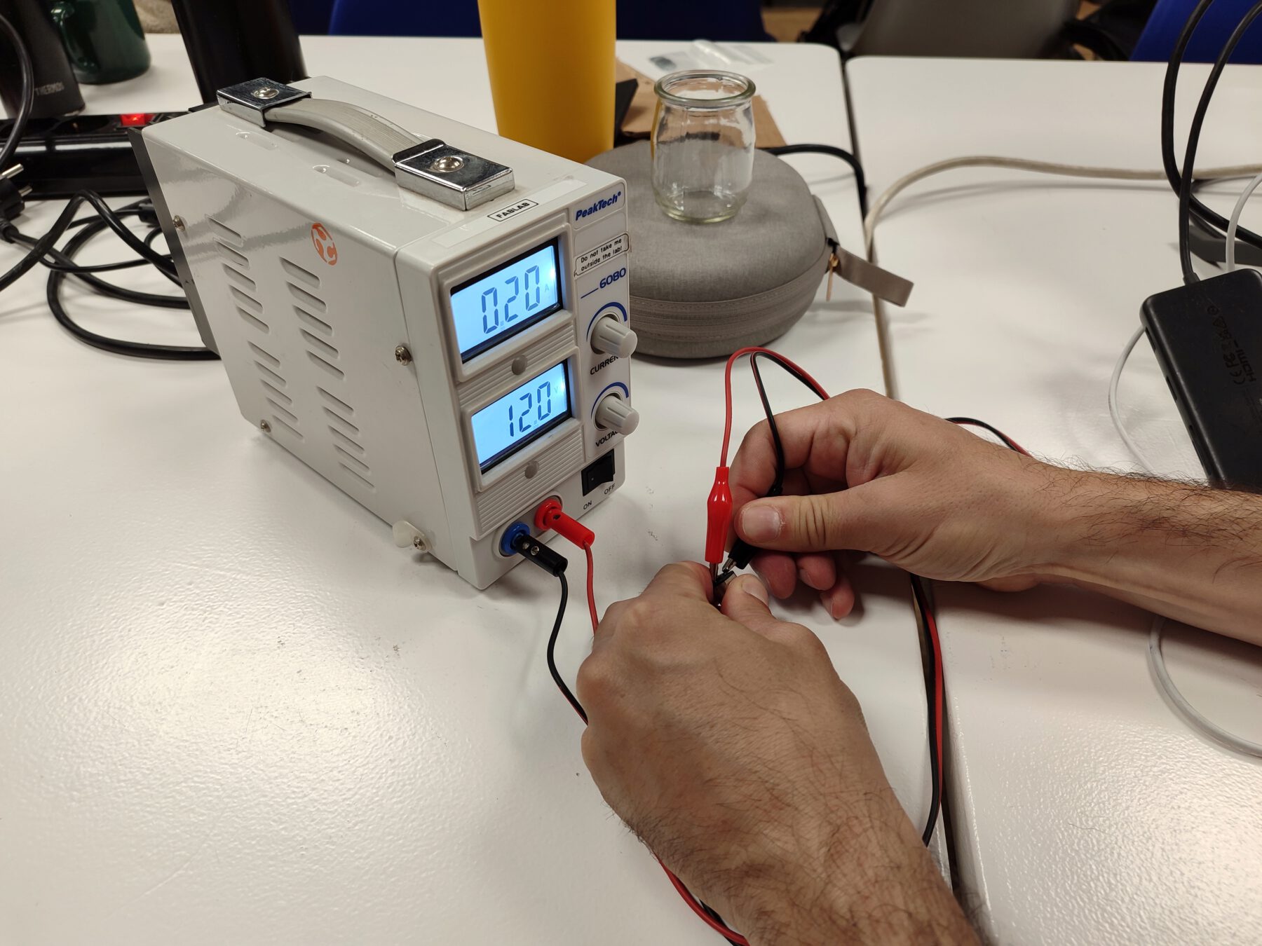
this week's group assignment was to measure the power consumption of an output device.
Here is the link to the group assignment page
DC Motor
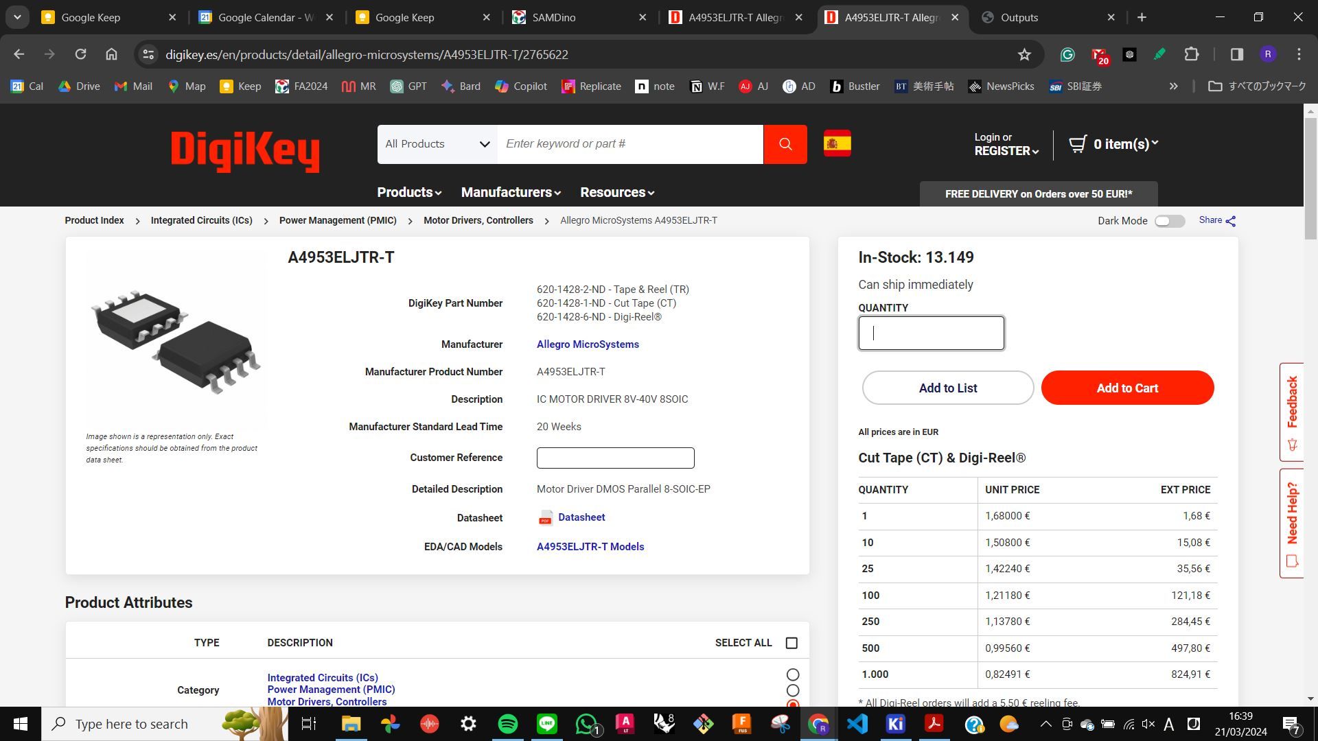
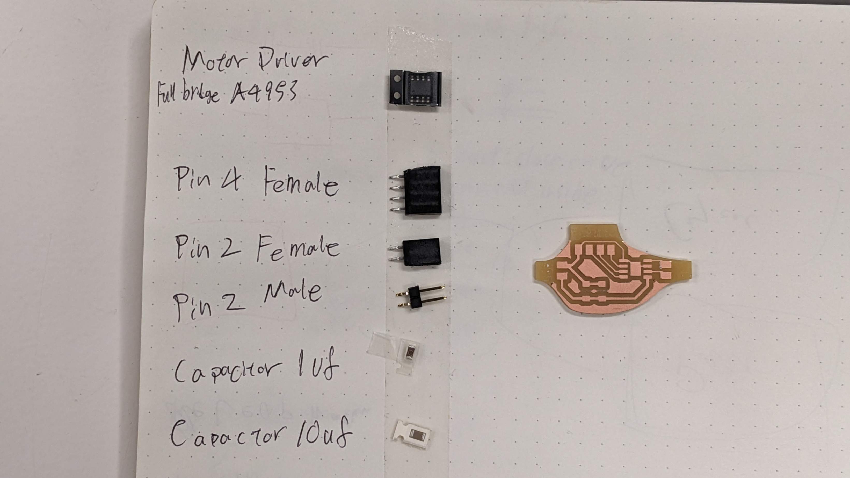
I wanted to try playing with the DC motor, which was shown to us during class. To control this DC motor I was advised to use the motor driver that was available in the lab (620-1428-1-ND | IC MOTOR DRIVER 8V-40V Parallel). I research the number (620-1428-1-ND) on Google and find out the product page for this motor driver ( Allegro MicroSystems A4953ELJTR-T )
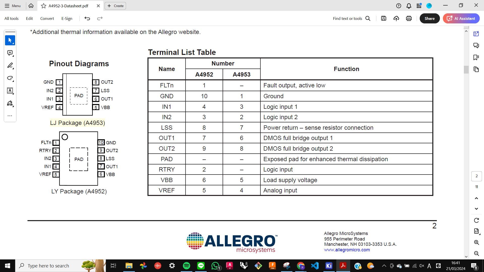
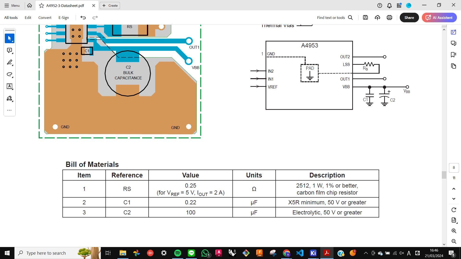
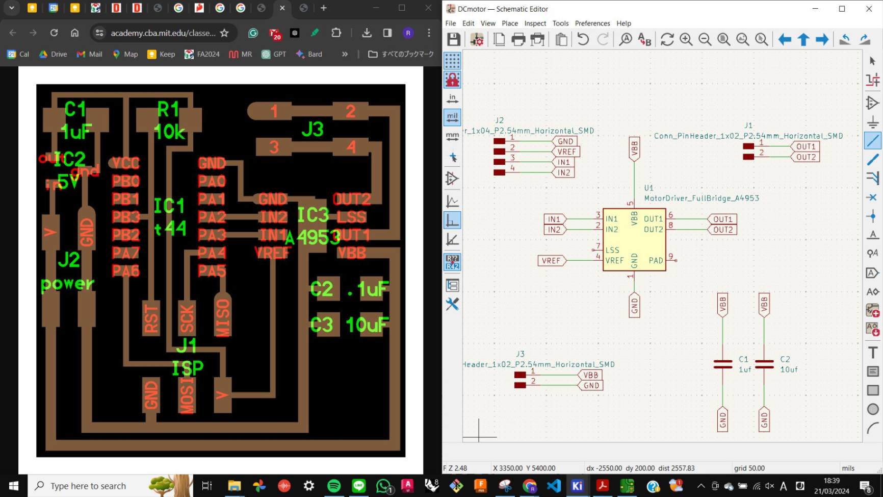
As always I started by looking at the datasheet. It was very difficult for me to know how this motor driver worked and what components I needed to make it work. So I used Neil’s example and SAMDino by Adrian Torres. However, I was not fully sure about What to connect to this motor driver. So I asked my tutor Josep, and he made me understand better. Basically, all I needed was below.
- Allegro A4953 (the motor driver)
- 4 pin header (IN1, IN2, VREF, GND) for inputs and voltage reference from SAMD11
- 2 pin header (VBB, GND) for external power supply
- 2 pin header (OUT1, OUT2) for DC motor
- 2 capacitor (1uf, 10uf) for making safer
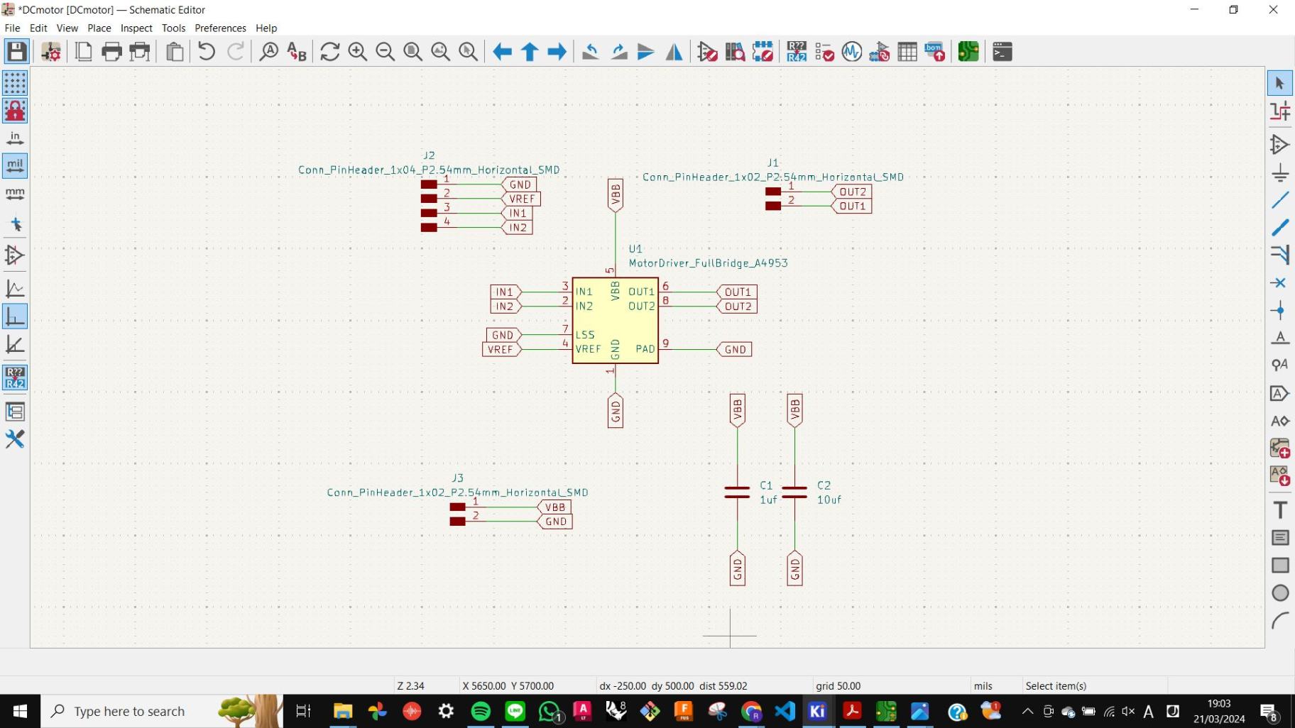
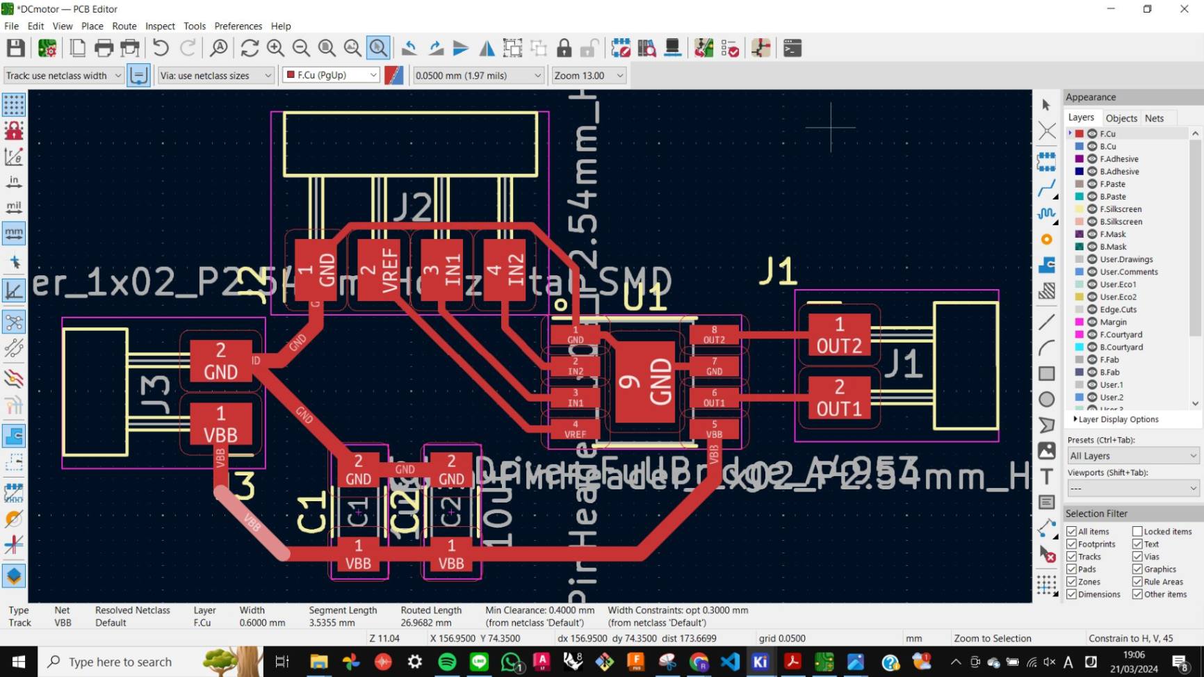
Design PCB
I design the PCB following the step from
Week 8 Electronic Design.
There were 2 new things I learned from this. One is that it is important to align input pins and output pins. In my case, when I designed output pins for SAMD11, I placed in this order GND, VDD, PA05, PA08, PA09. So the 4 input pins for the A1953 Motor driver, should also be placed in this order GND, VREF, IN1, IN2
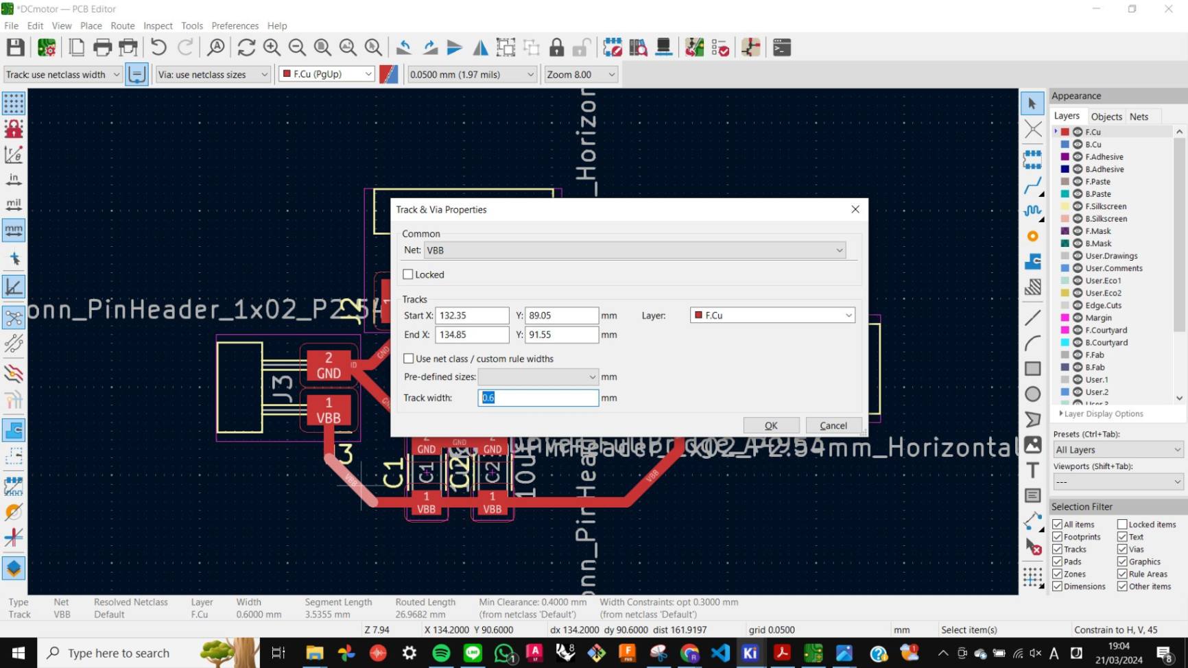
Another thing is that when connecting with components with higher voltage, it is better to have a wider trace to make sure the voltage flows nicely. In my case, I made it 0.6mm wide which is double of normal trace.
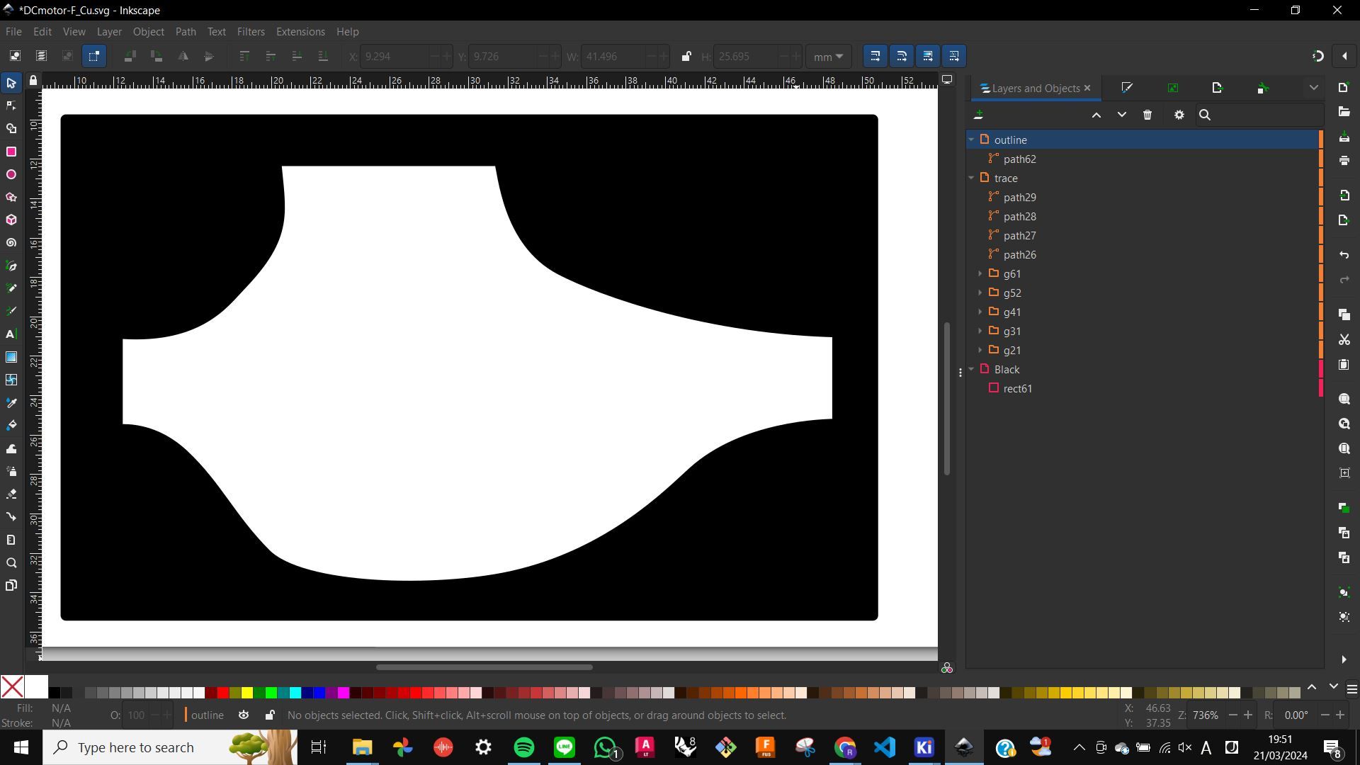
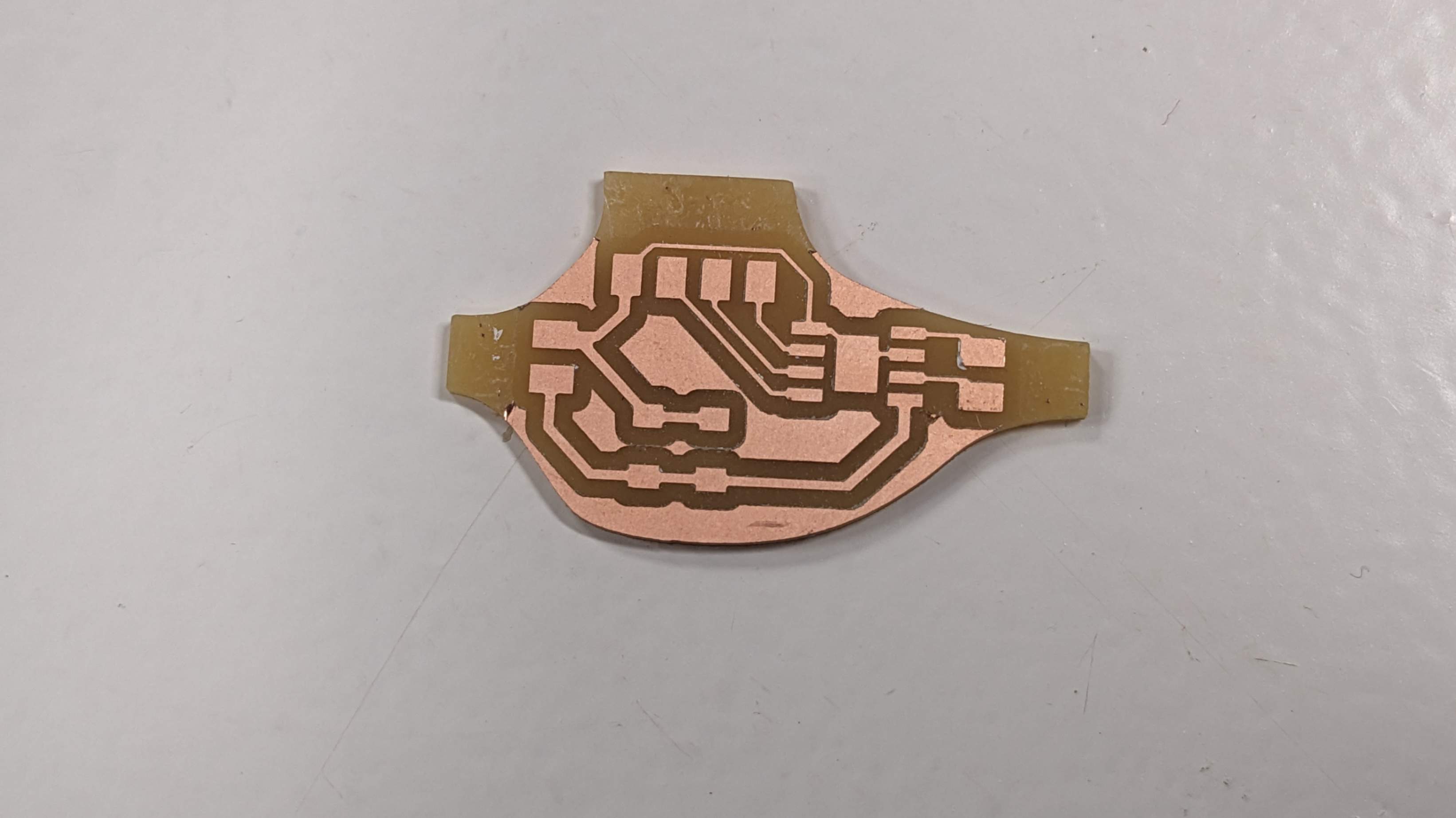
After that, I did the rest of the process with the same workflow of
Week 8 Electronic Design.
Files
DCmotor.kicad_pro
DCmotor.kicad_sch
DCmotor.kicad_pcb
DCmotor-F_Cu.svg
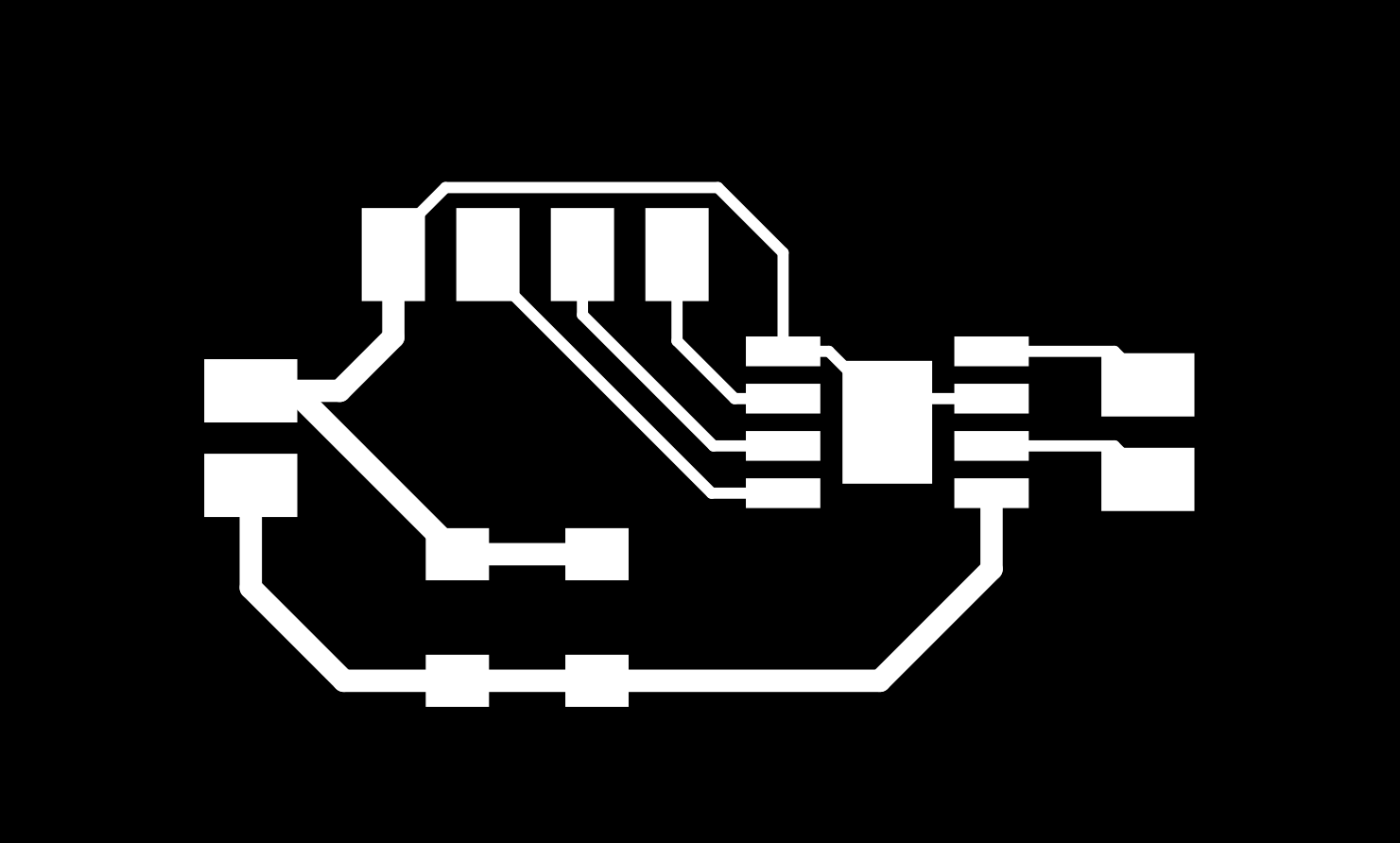
outline.png
trace.png
outline.png.rml
trace.png.rml
Programming for DC Motor
Programming for controlling the DC motor I used an example made by Adrian Torres And I changed pin number to fit with my SAMD11. It worked!! I was really happy finally making it work.
const int motor1Pin = 5;      // H-bridge pin 3 (IN1)
          const int motor2Pin = 8;      // H-bridge pin 2 (IN2)

          void setup() {
            // put your setup code here, to run once:
            // set H-bridge pins as outputs:
          pinMode(motor1Pin, OUTPUT);
          pinMode(motor2Pin, OUTPUT);
          }

          void loop() {
            // put your main code here, to run repeatedly:
            // change the direction the motor spins by talking to the control pins on the H-Bridge

              digitalWrite(motor1Pin, HIGH);    // Turn the motor in one direction
              digitalWrite(motor2Pin, LOW);

              delay(2000);                      // Wait two seconds

              digitalWrite(motor1Pin, LOW);     // Switch off the motor
              digitalWrite(motor2Pin, LOW);

              delay(3000);                      // Wait three seconds

              digitalWrite(motor1Pin, LOW);
              digitalWrite(motor2Pin, HIGH);    // Turn the motor in the other direction


              delay(2000);                      // Wait two seconds

              digitalWrite(motor1Pin, LOW);     // Switch off the motor
              digitalWrite(motor2Pin, LOW);

              delay(3000);                      // Wait three seconds
          }
Stepper Motor
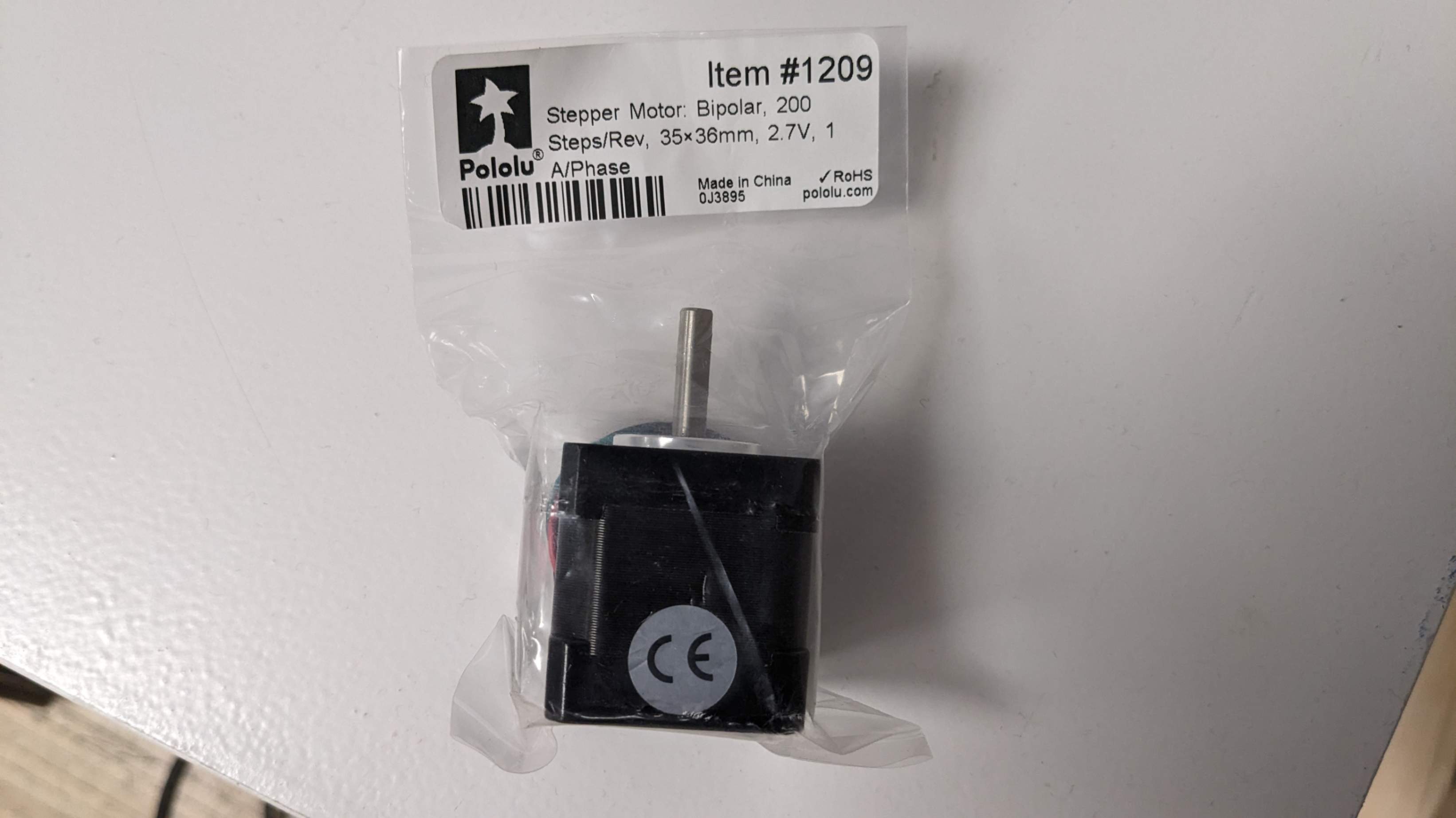
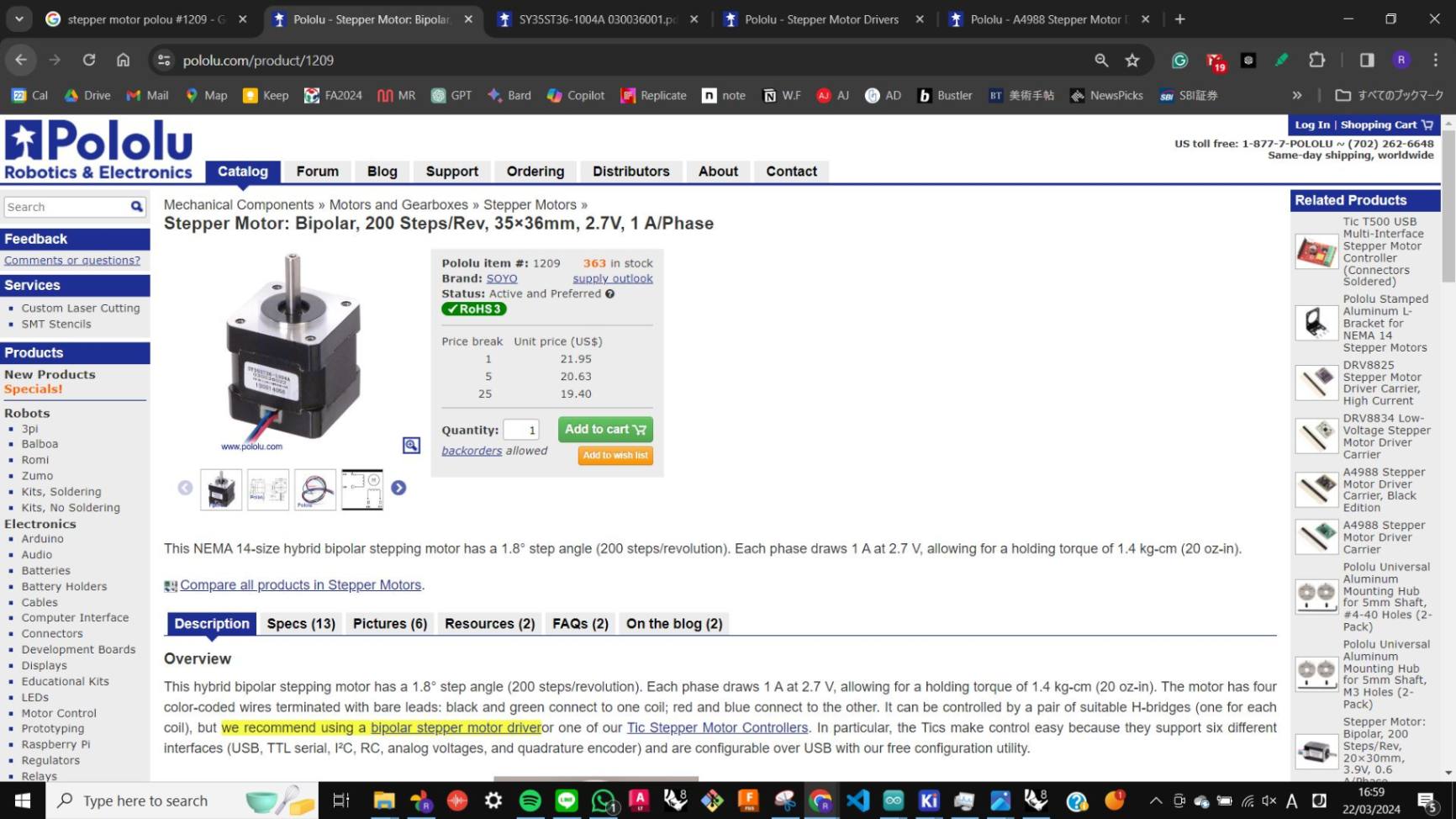
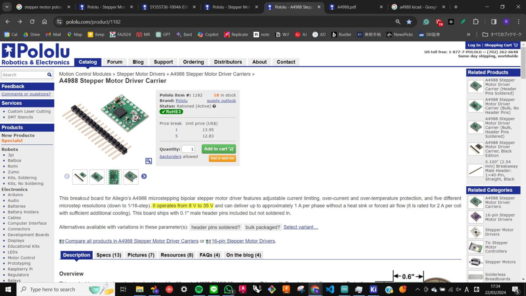
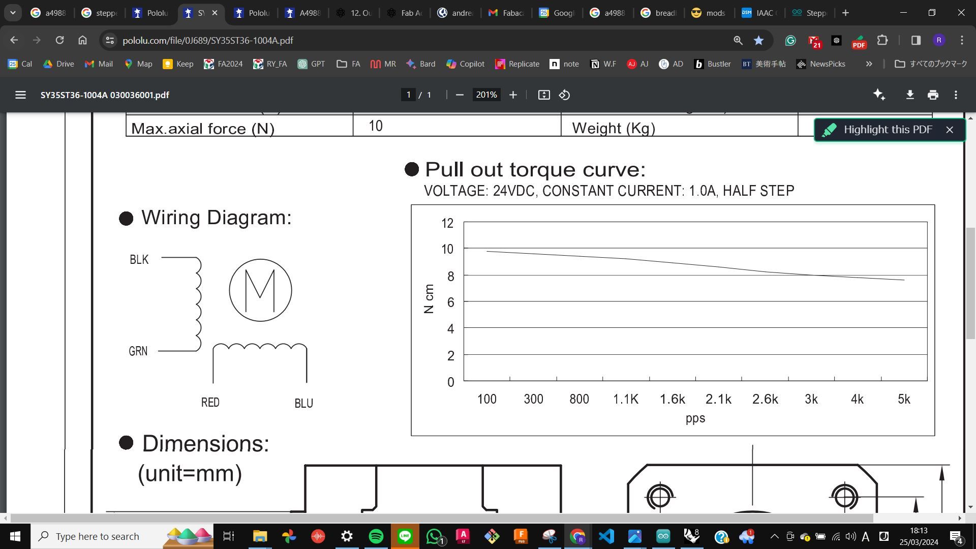
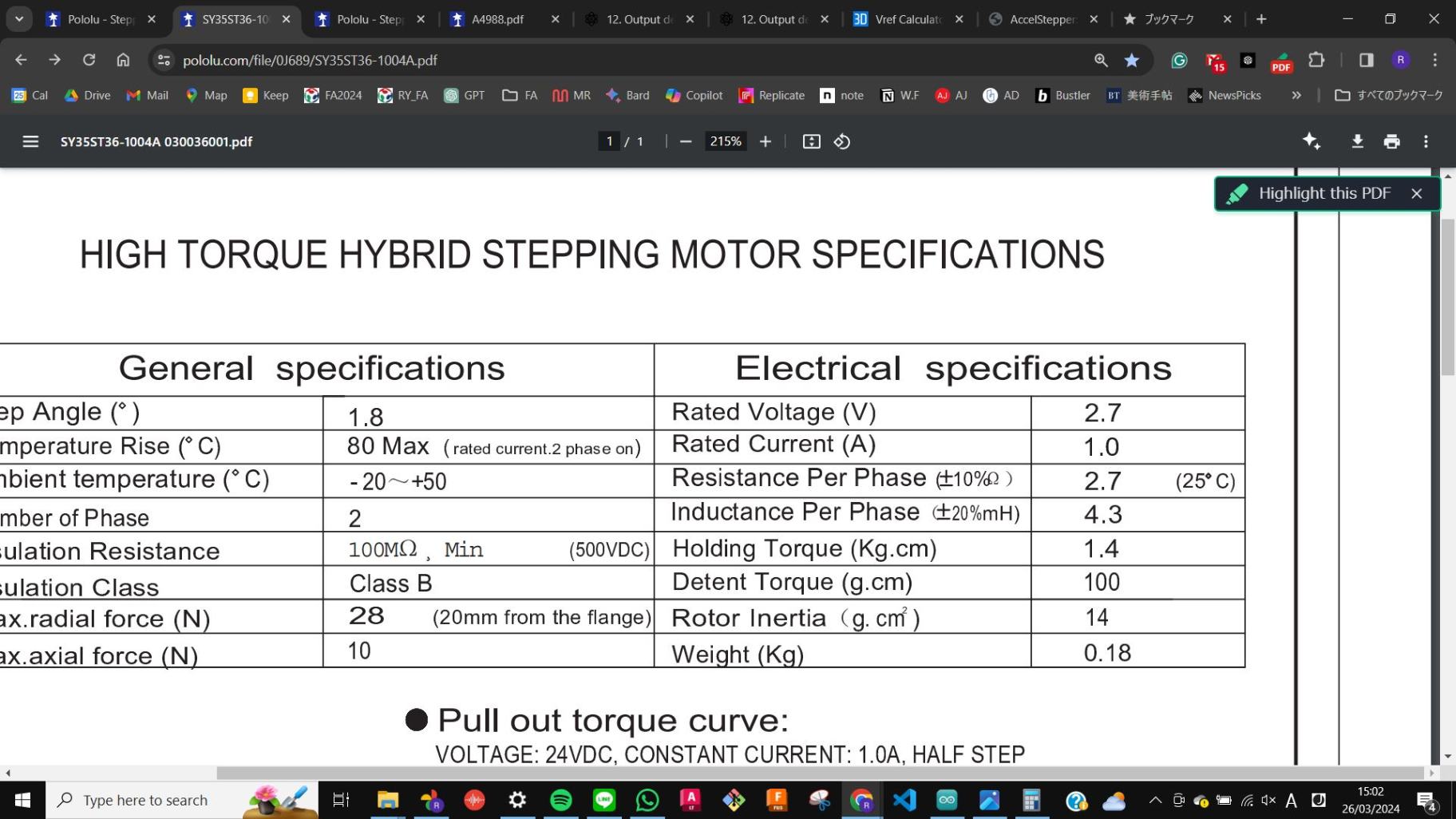
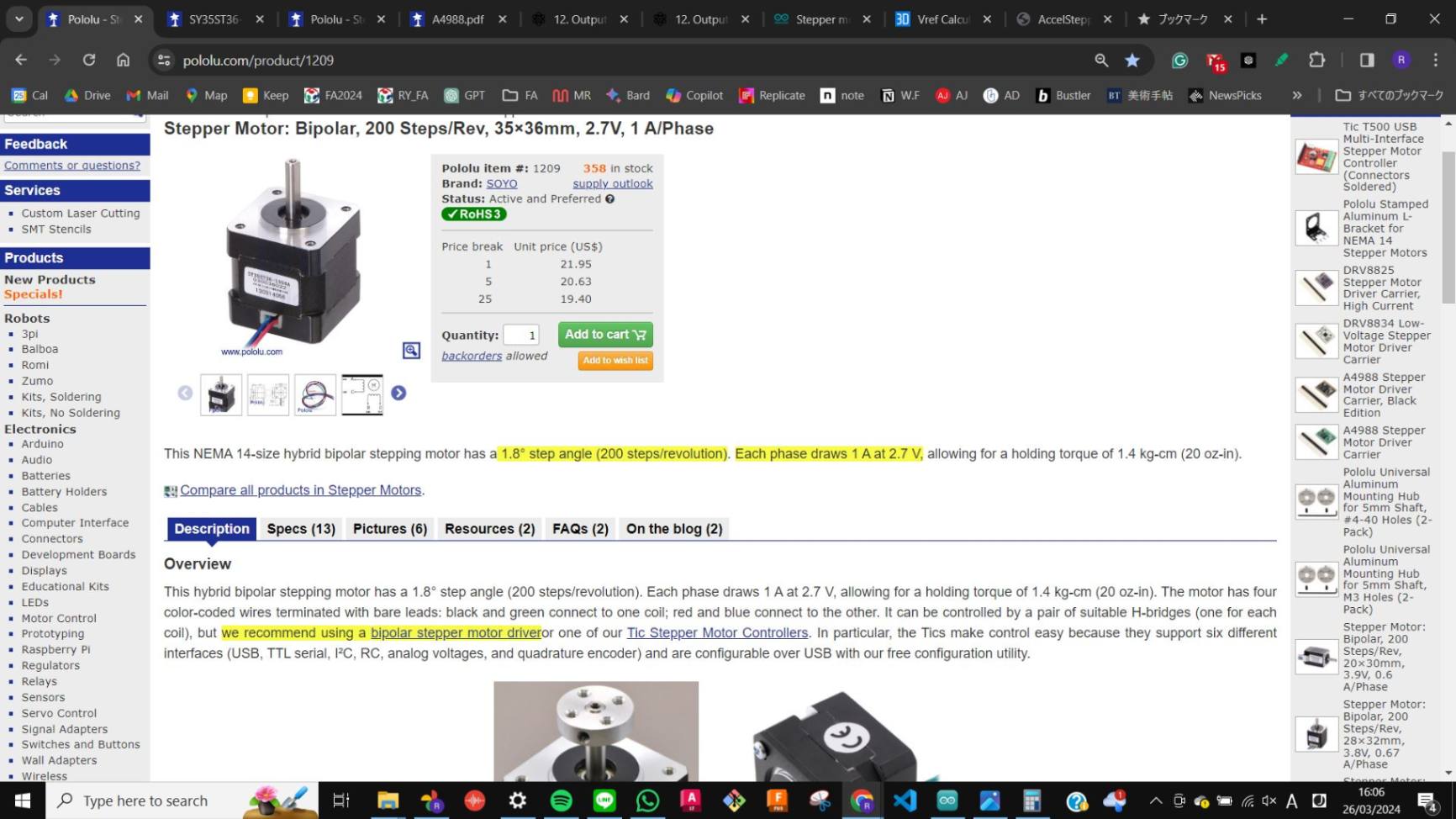
Next, I wanted to try stepper motors because most of the 3d printer uses them. By asking my tutor I found a stepper motor from Pololu (Bipolar, 200, Item #1209)
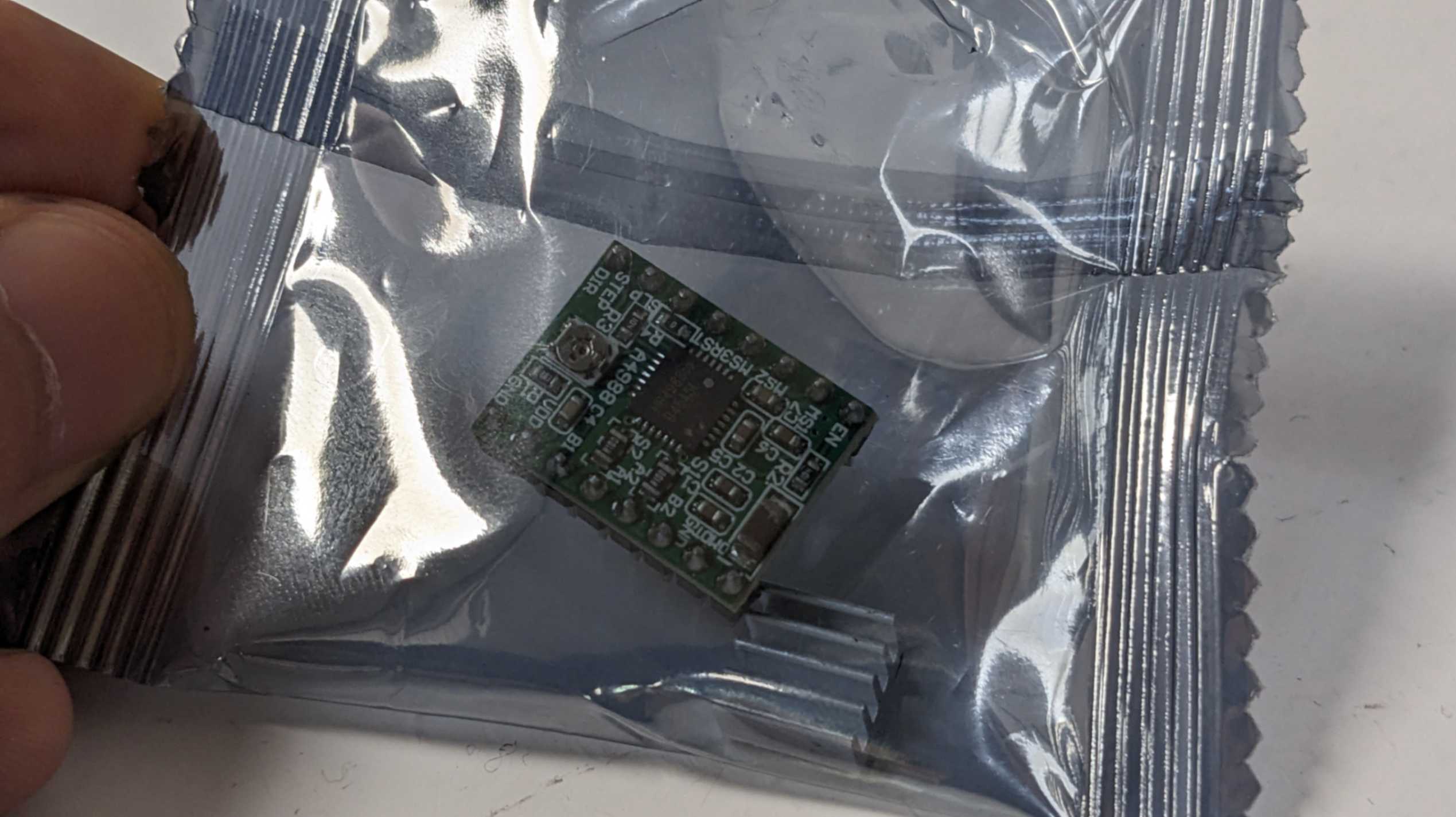
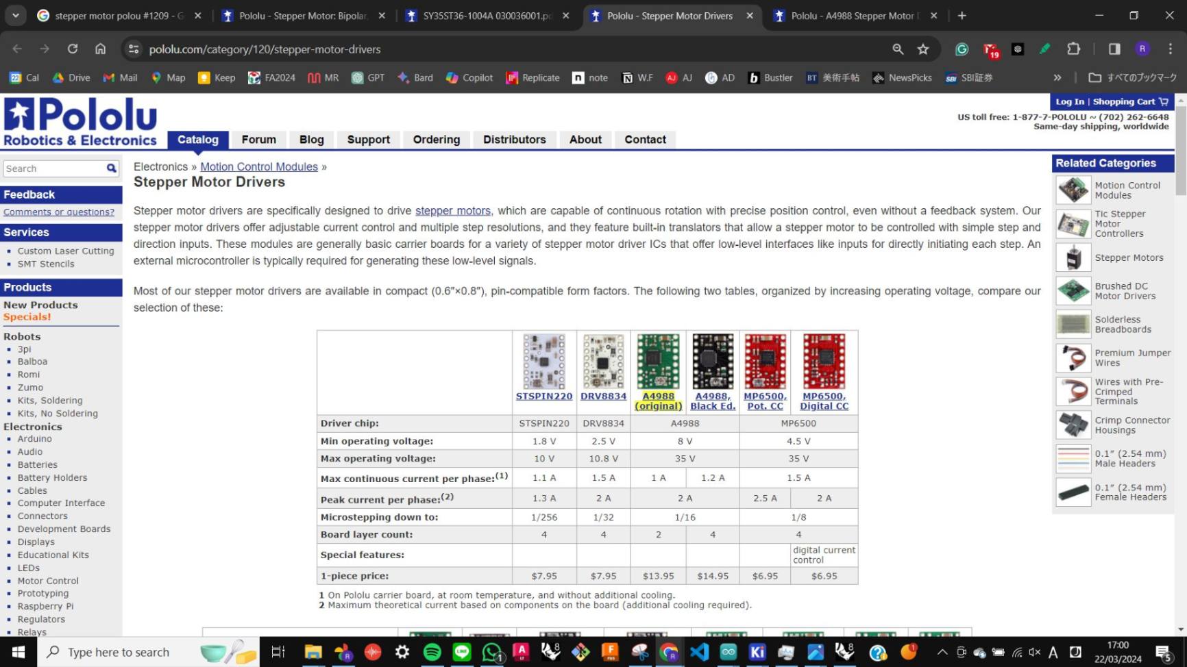
Also, I was advised by my tutor to use So I used a motor driver (A4988), which is also recommended by Pololu.
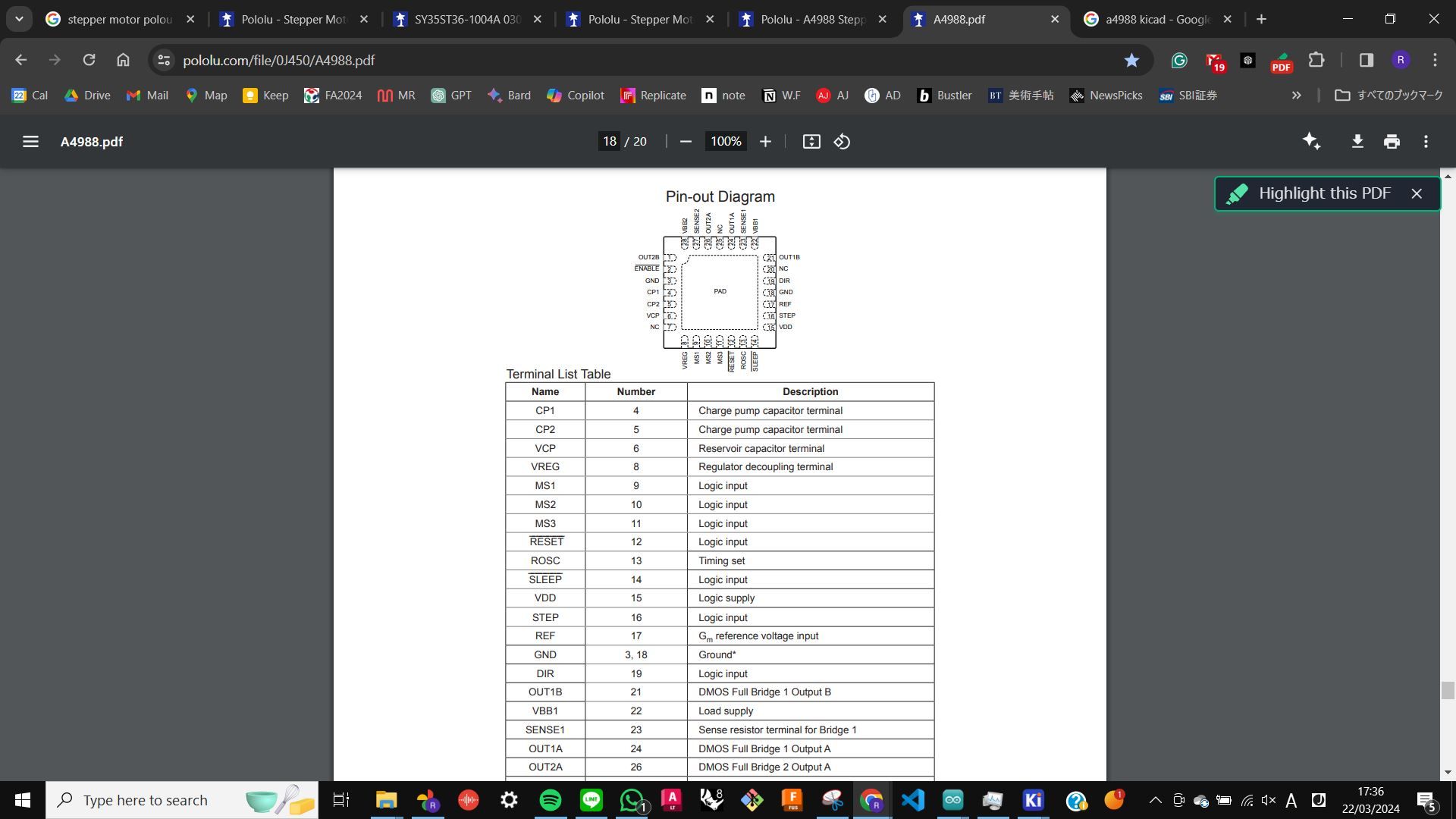
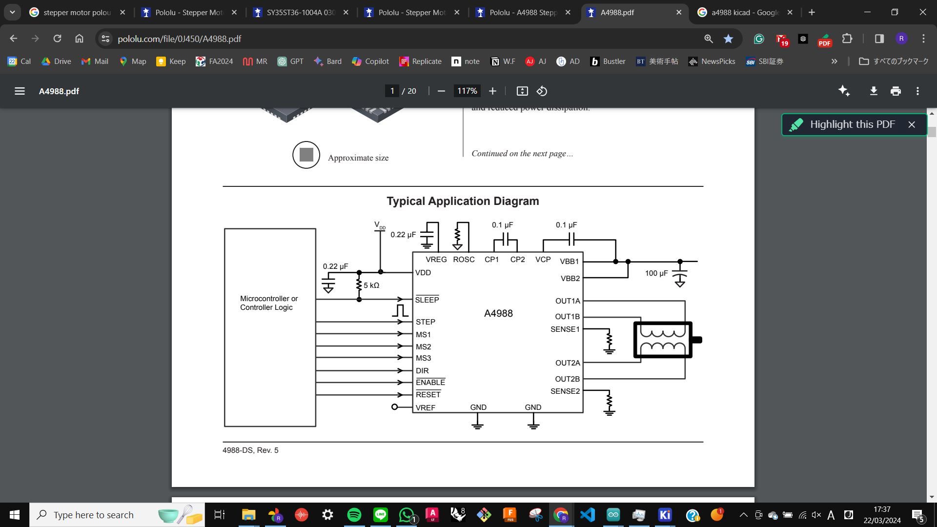
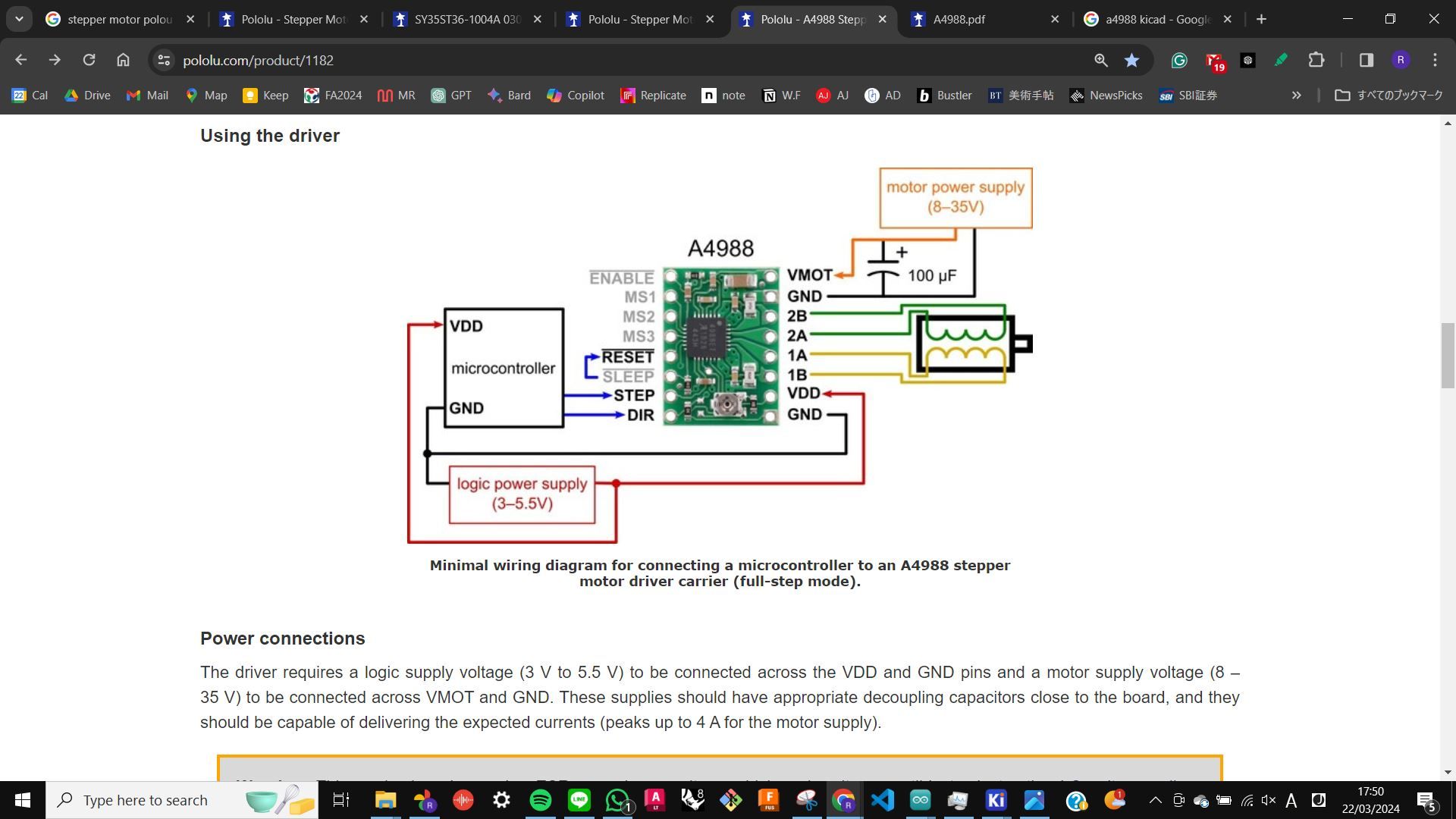
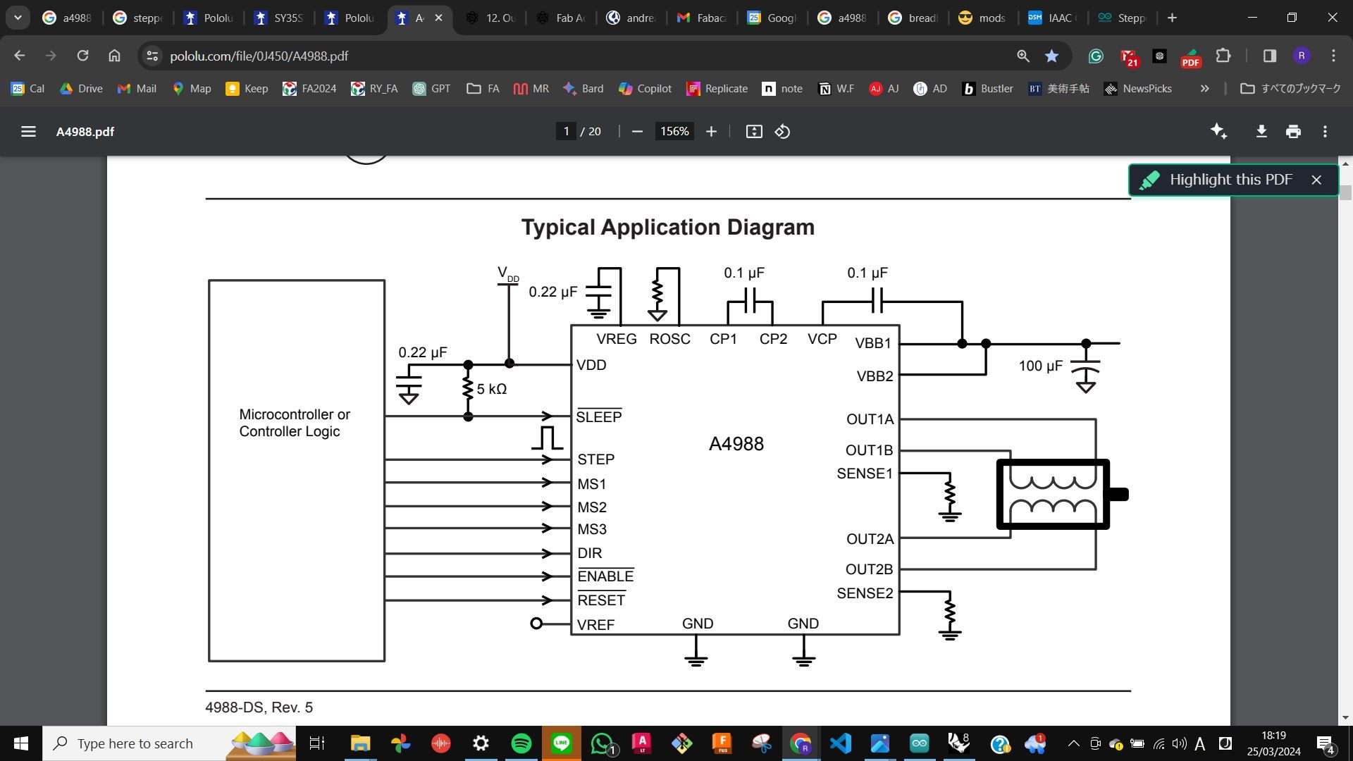
As always, I started by researching both products and checking the datasheet and pinouts. I decided to work with a minimal wiring diagram that I found on the motor driver product page.
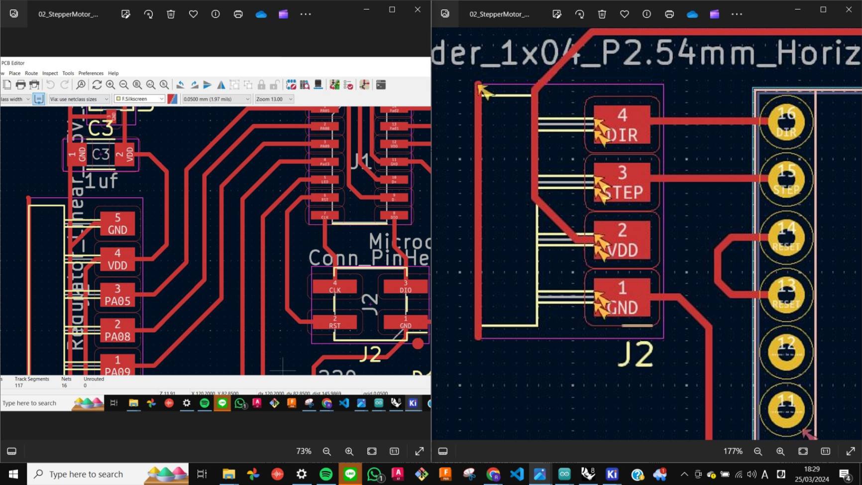
Kicad
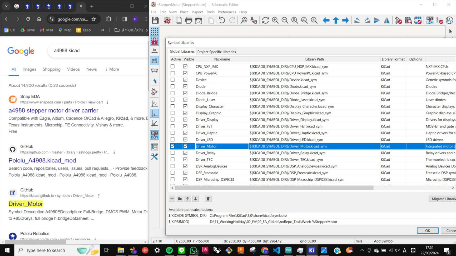
Then I move on to Kicad to make schematics and PCB design. First I could not find the motor driver symbol in the Kicad library, but my tutor advised me to search A4988 Kicad on Google then I found out that I needed to activate the Driver_Motor library which is a default library that I deactivated when I used Kicad for the first time.
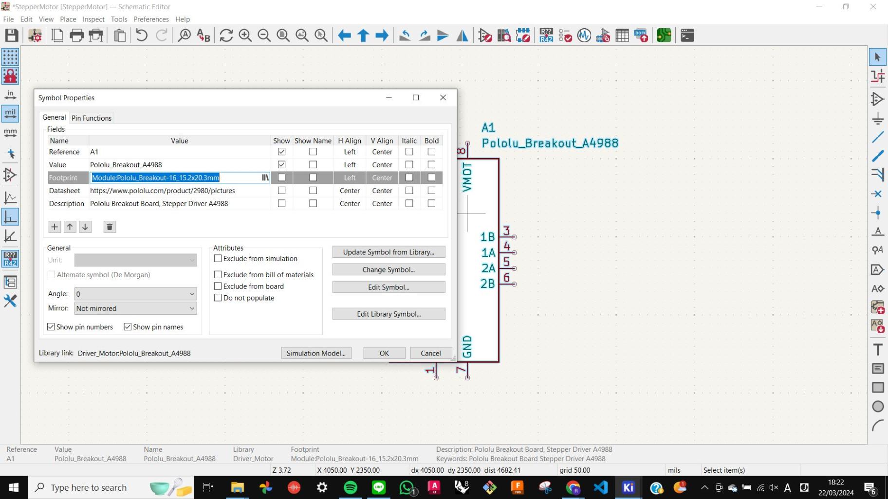
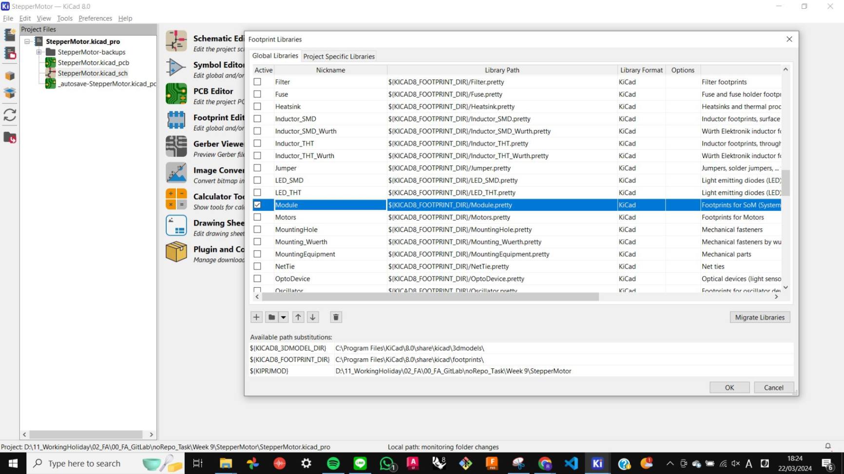
Also, I needed to activate the Module library to get the footprint of the motor driver. This can be checked when I add the symbol to the schematic and open the Symbol Properties window, in the Footprint box it shows ModulePololu_Breakout-16_15.2x20.3mm.
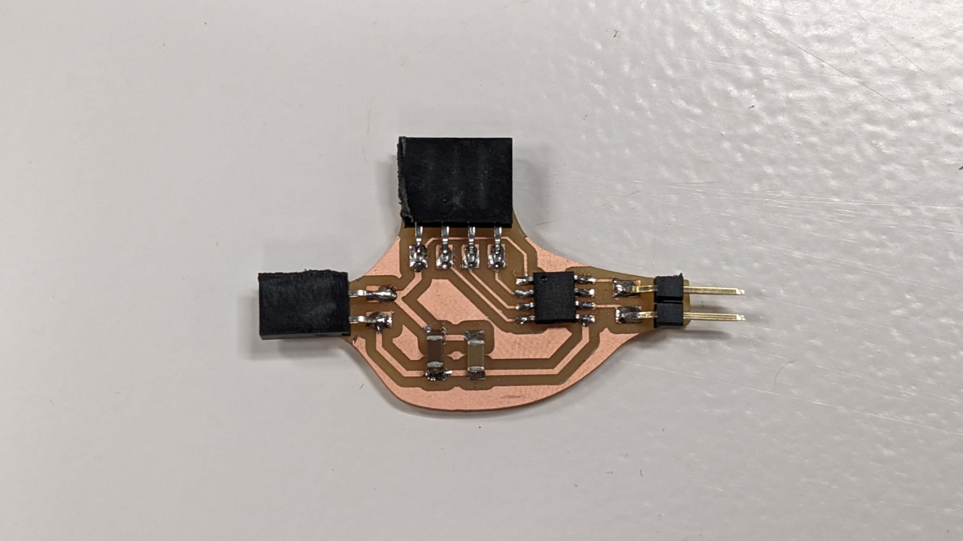
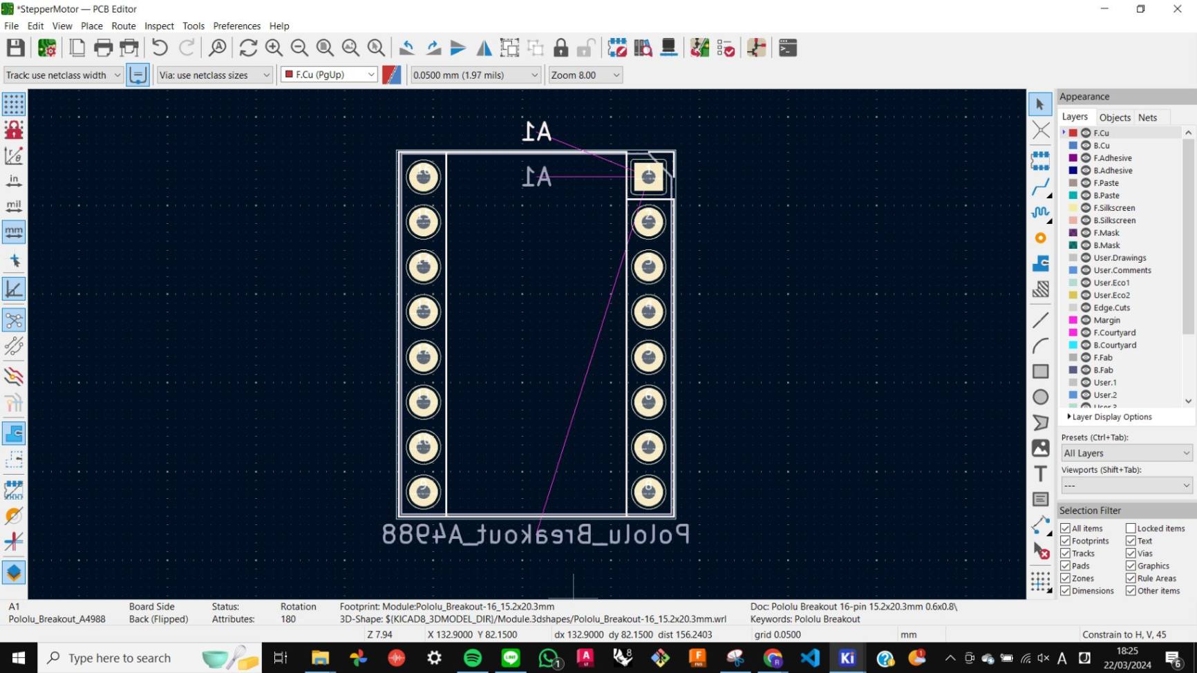
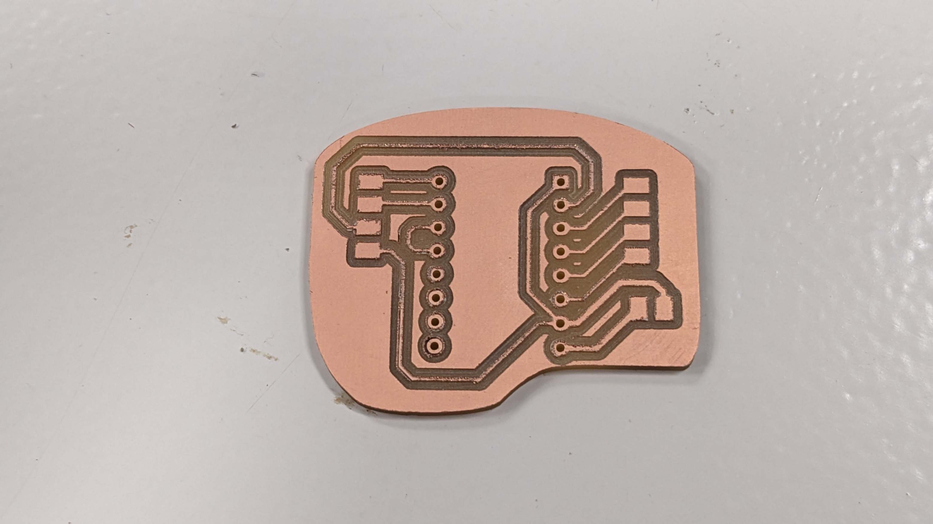
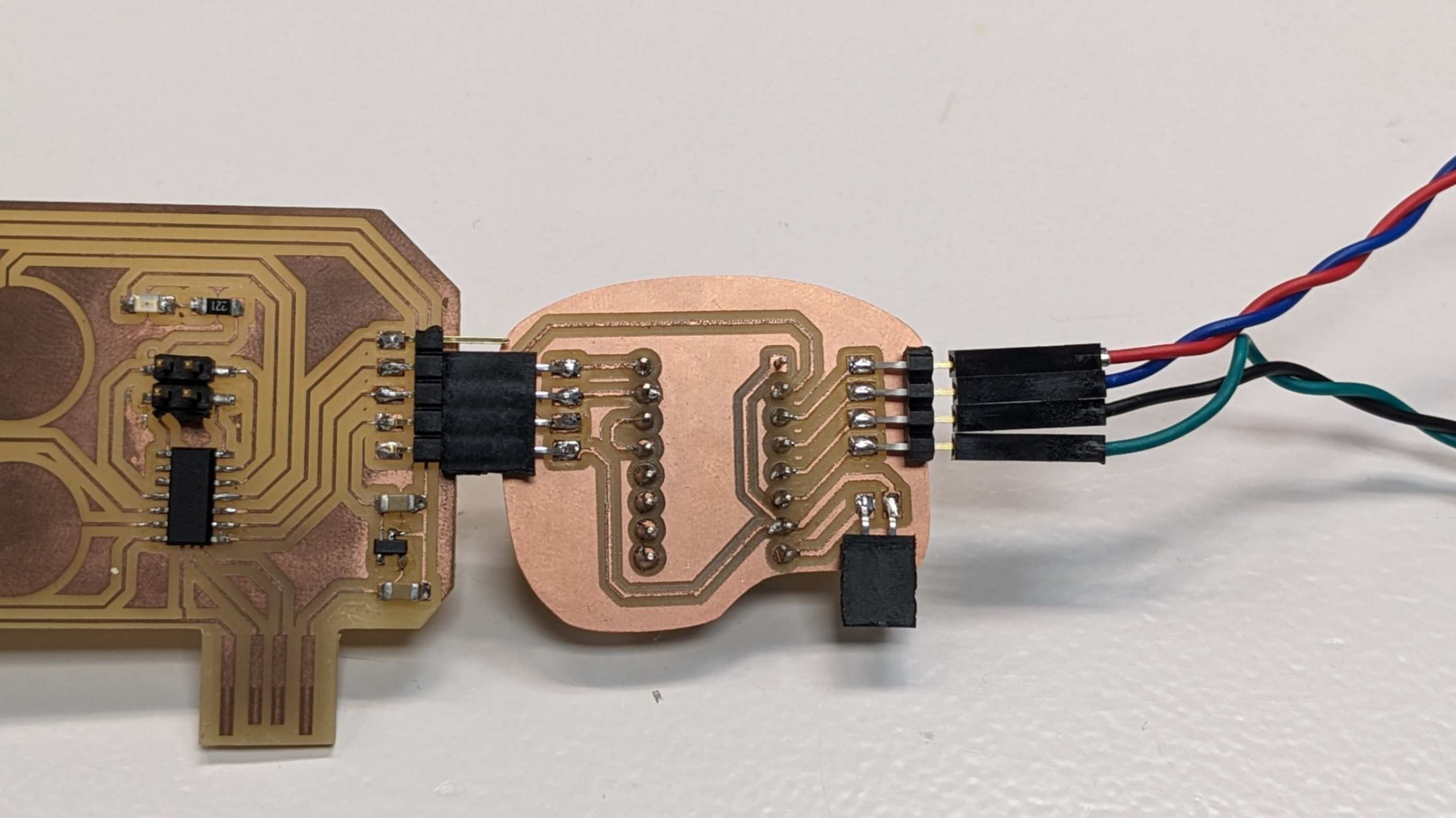
When designing the PCB, my tutor advised me to flip the motor driver in Kicad, and solder from the back of the PCB. This was because the copper board for the PCB is only onesided and pins from the motor driver needed to be connected to the copper side.
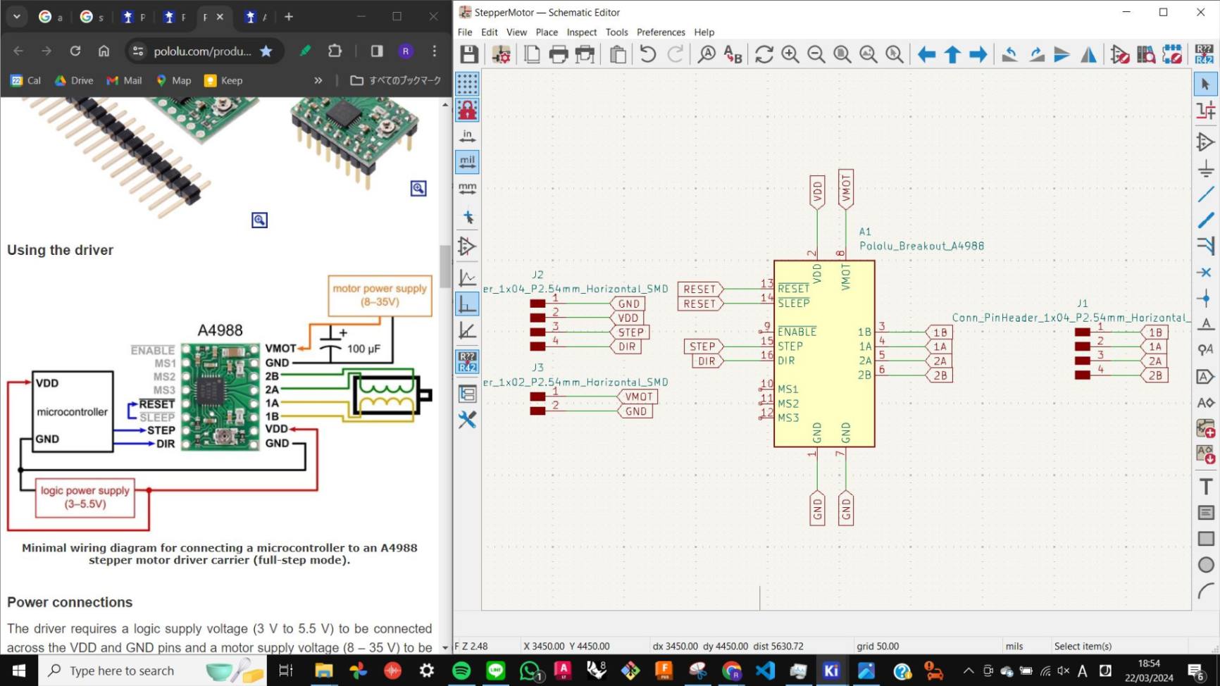
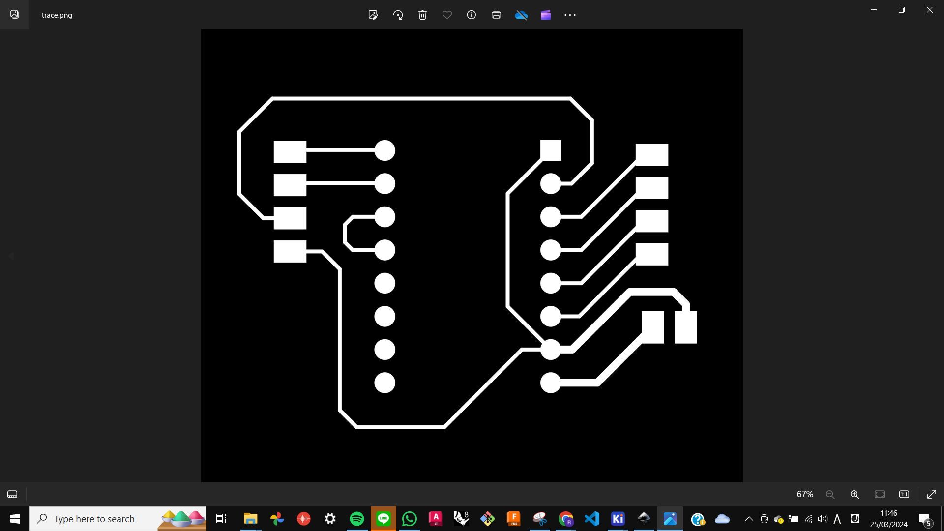
For the Schematic I simply analysed the minimal diagram that I found and replicated it. The motor driver needs
- 4 pins connecting a microcontroller, such as GND, VDD (logic power supply), STEP, and DIR
- 2 pins connecting the motor power supply, such as VMOT, and GND
- 4 pins connecting the motor, 2 for each phase
- a connection between SLEEP and RESET
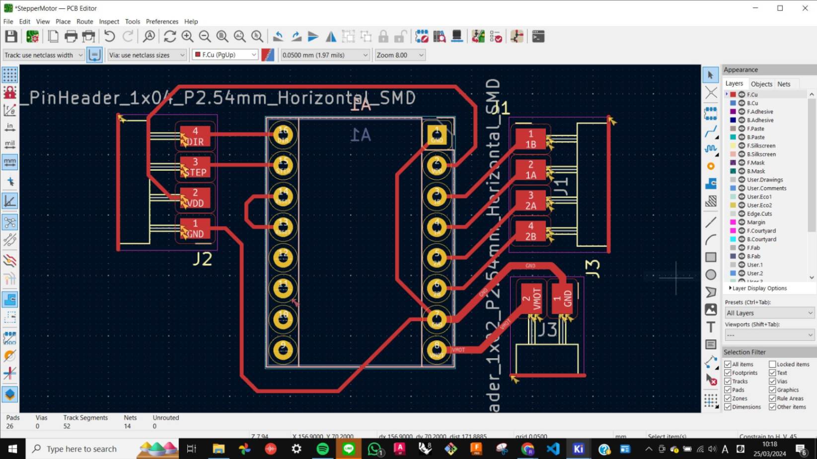
Also, I was advised to make traces connecting the motor power supply and the motor driver to make sure more voltage flows smoothly. I made it 0.6mm thick.
I did the rest of the process with the same workflow of Week 8 Electronic Design.
Files
StepperMotor.kicad_pro
StepperMotor.kicad_sch
StepperMotor.kicad_pcb
StepperMotor-F_Cu.svg
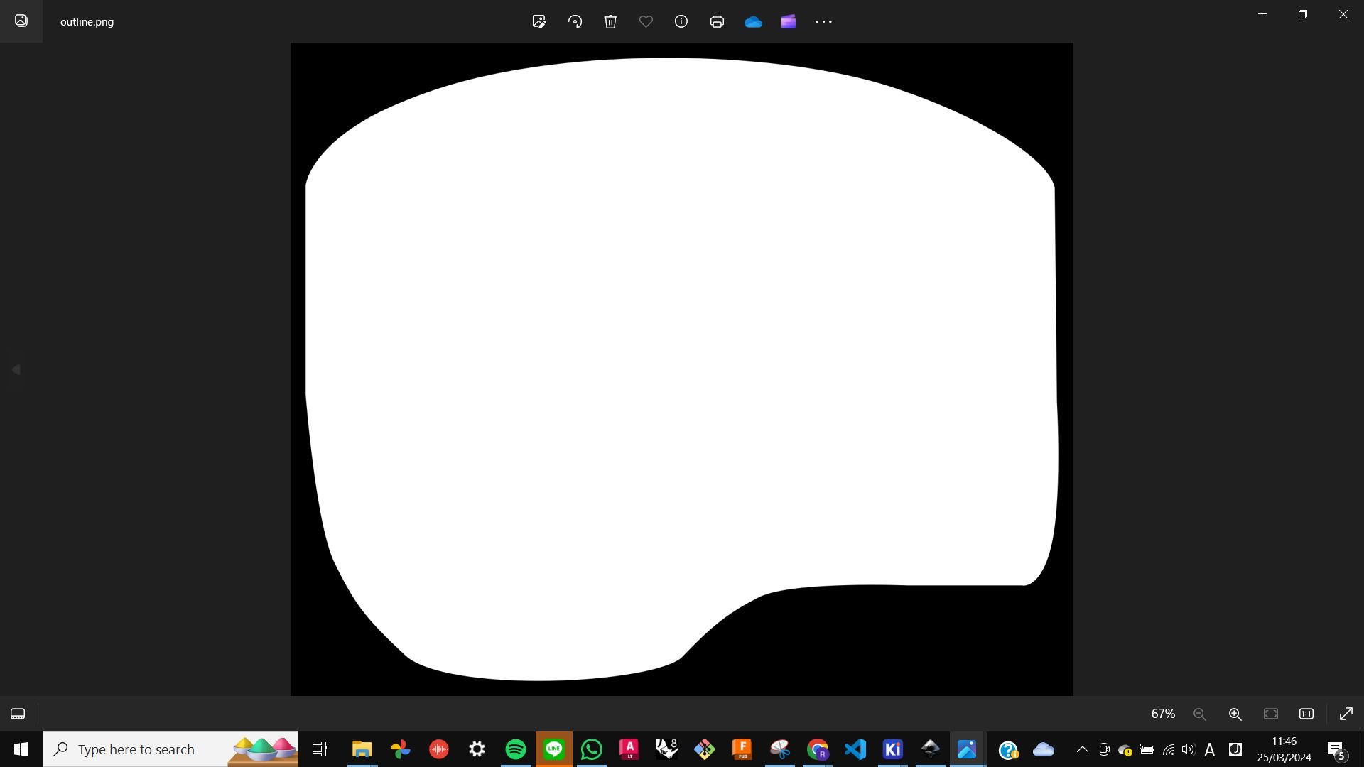
outline.png
holes_0.81mm.png
outline.png.rml
holes_0.81mm.png.rml
trace.png.rml
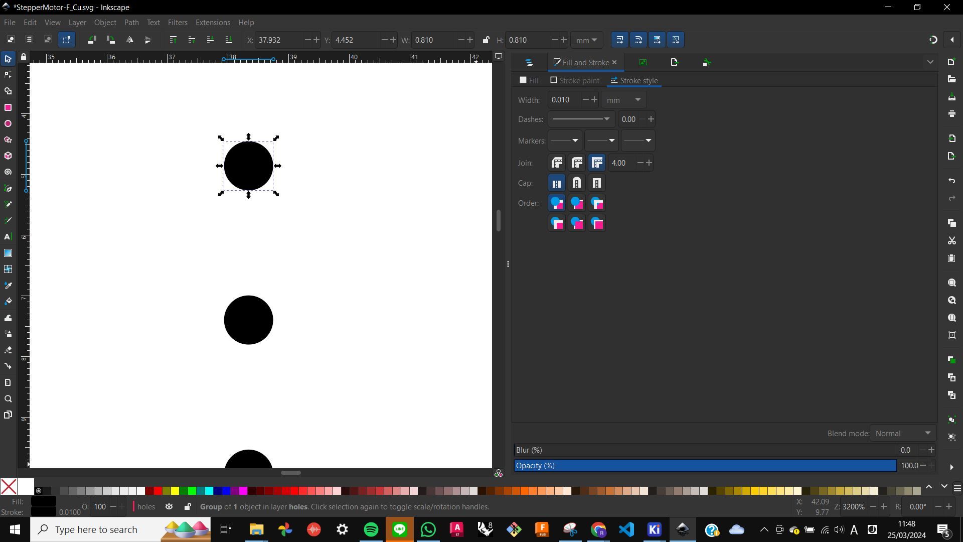
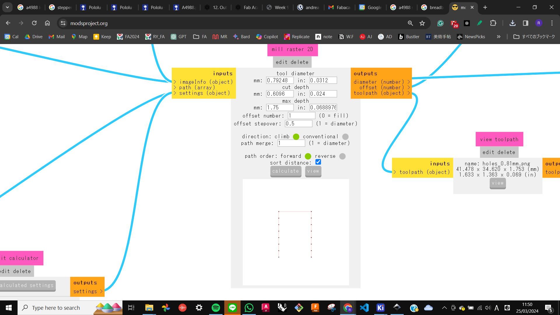
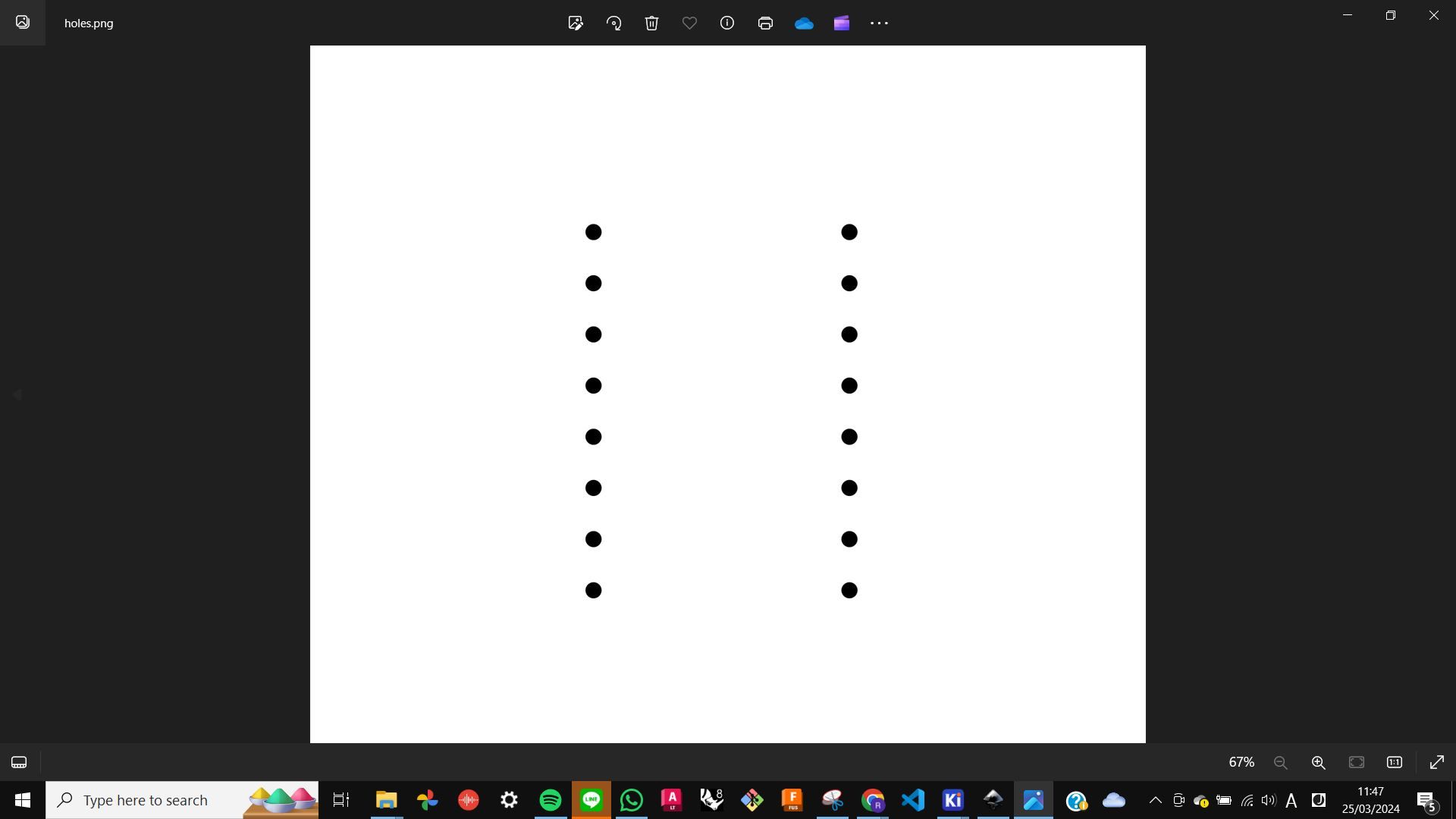
Problem
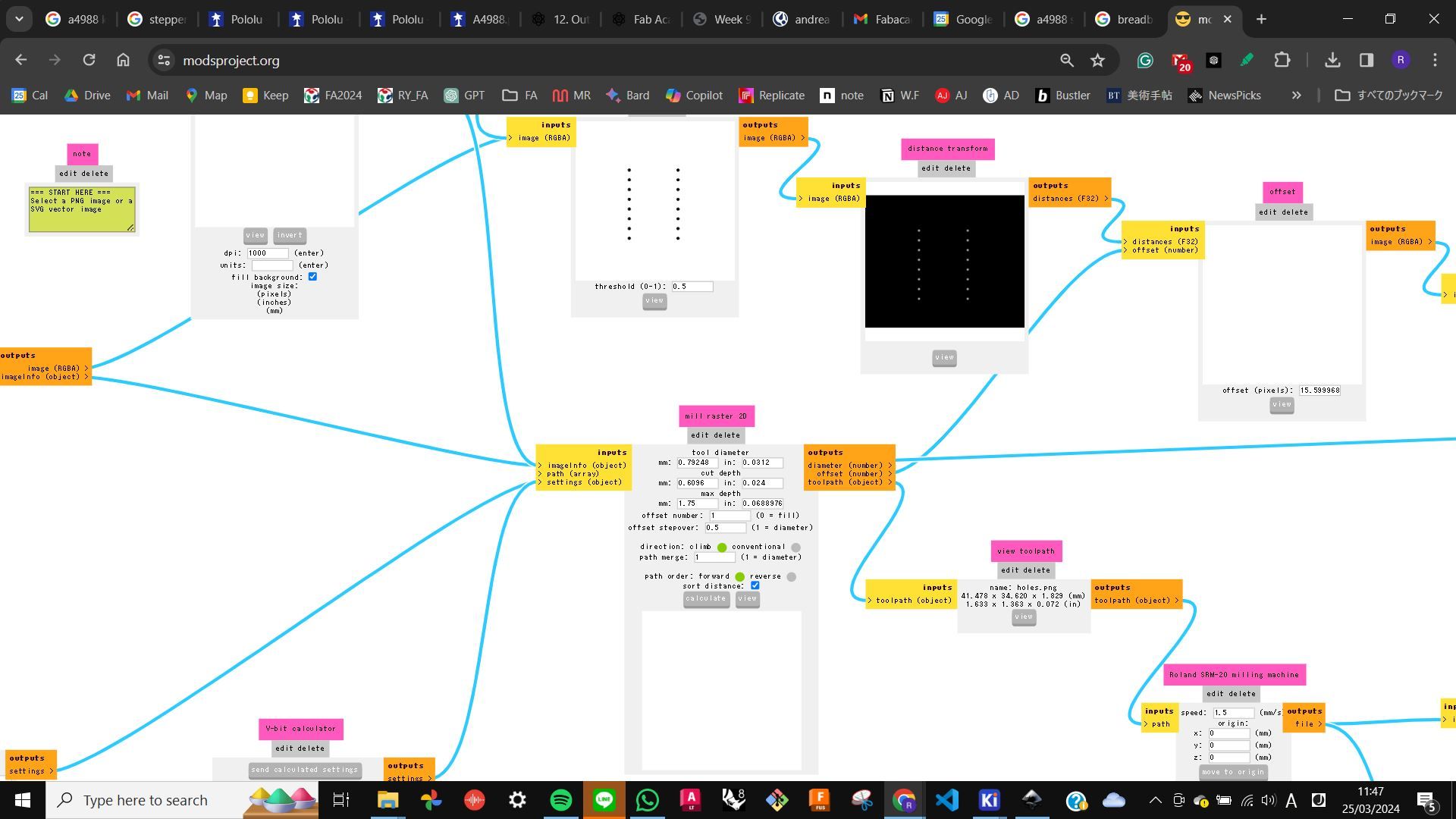
When I was preparing the file in MODS, it was not calculating for the hole, so I asked for help to my tutor. Later we found out that there was some error happening during the offset conversion phase, so we added a 0.001mm stroke to the holes in Inkscape and it calculated correctly.
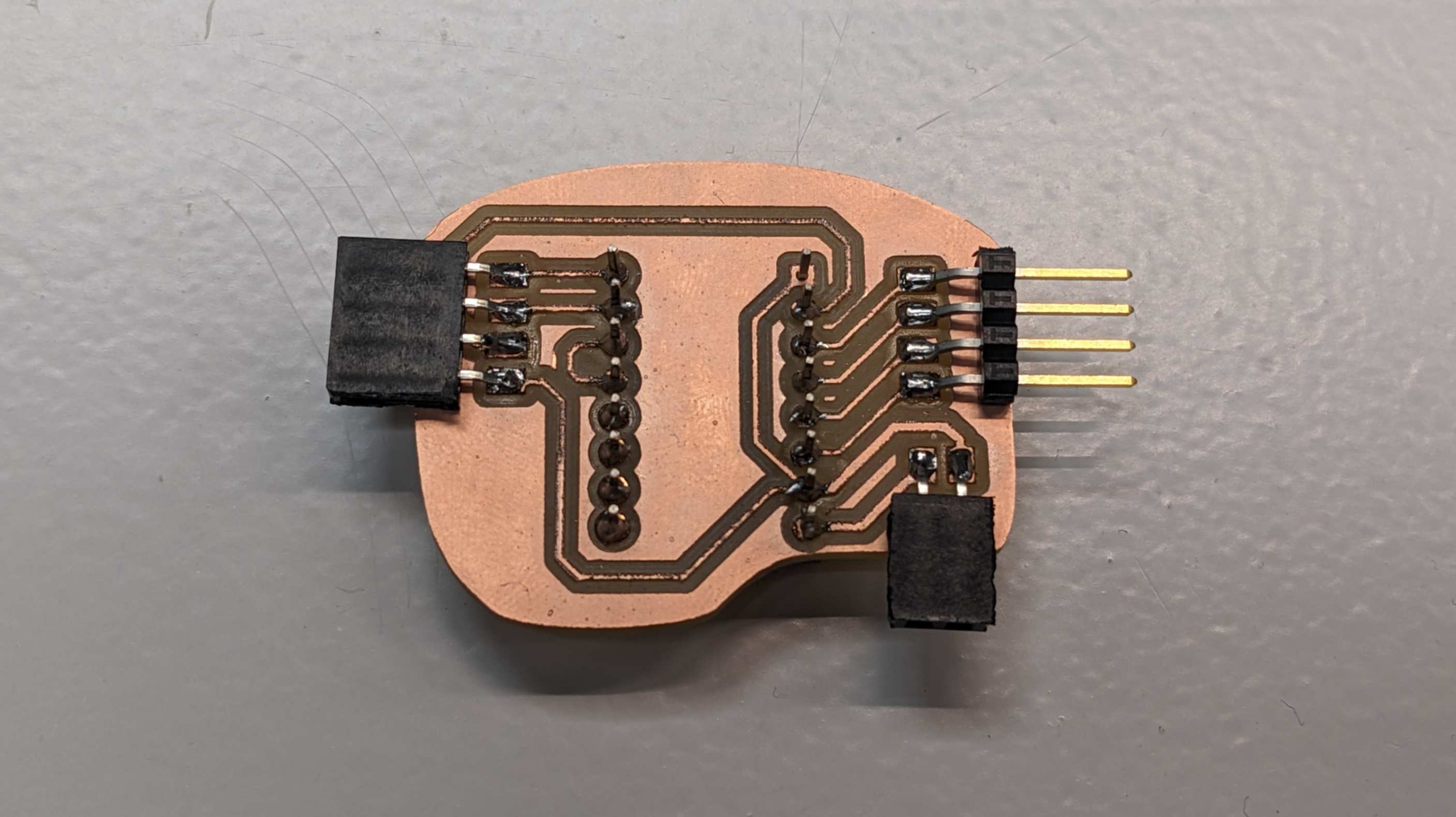
Connection
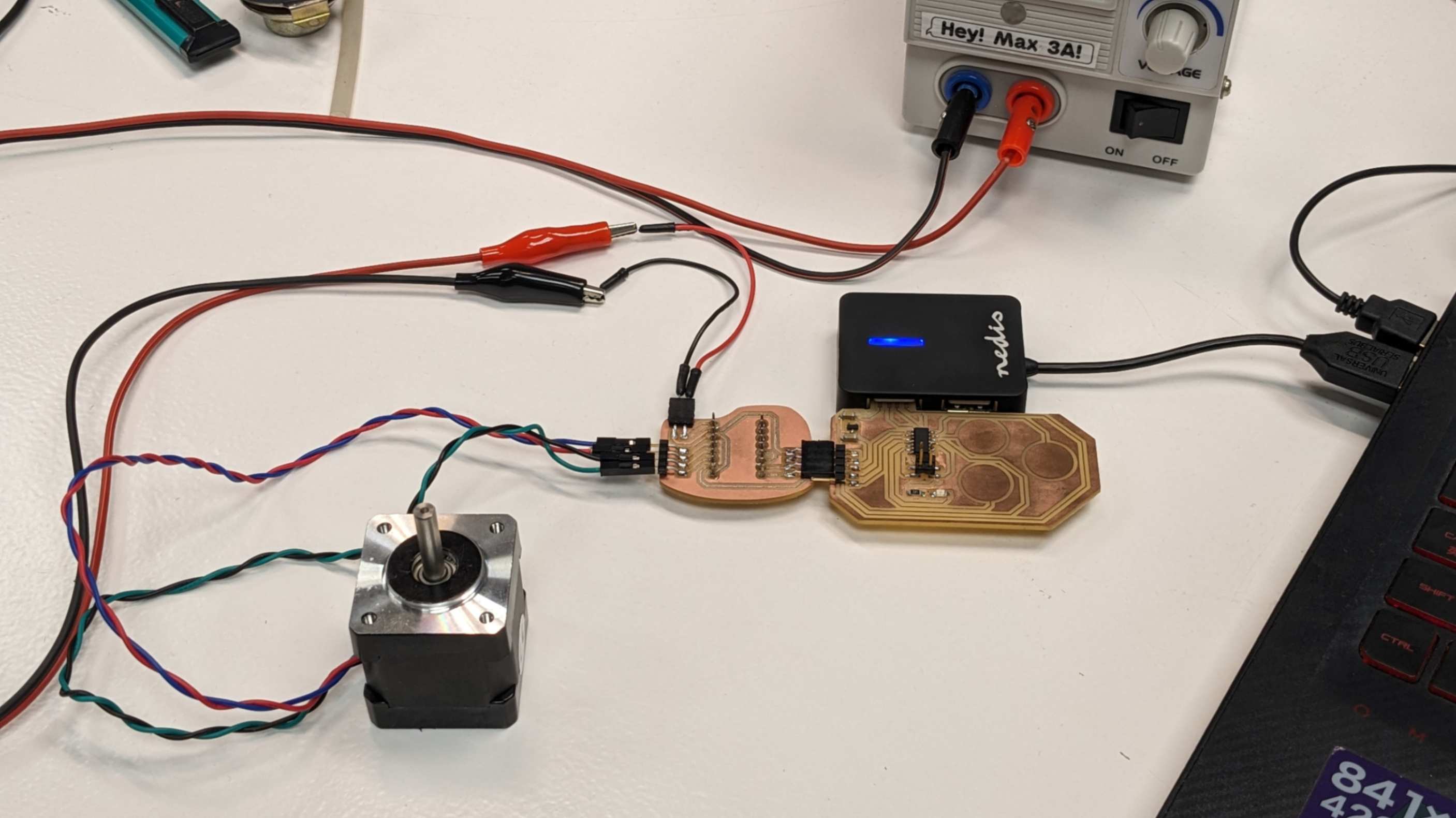
After milling the PCB and soldering components on it, I moved on to making the connection with the microcontroller and the stepper motor.
For the microcontroller, I used the development board that I made during Week 8 Electronic Design. I just needed to check the pin connection between the development board and this PCB.
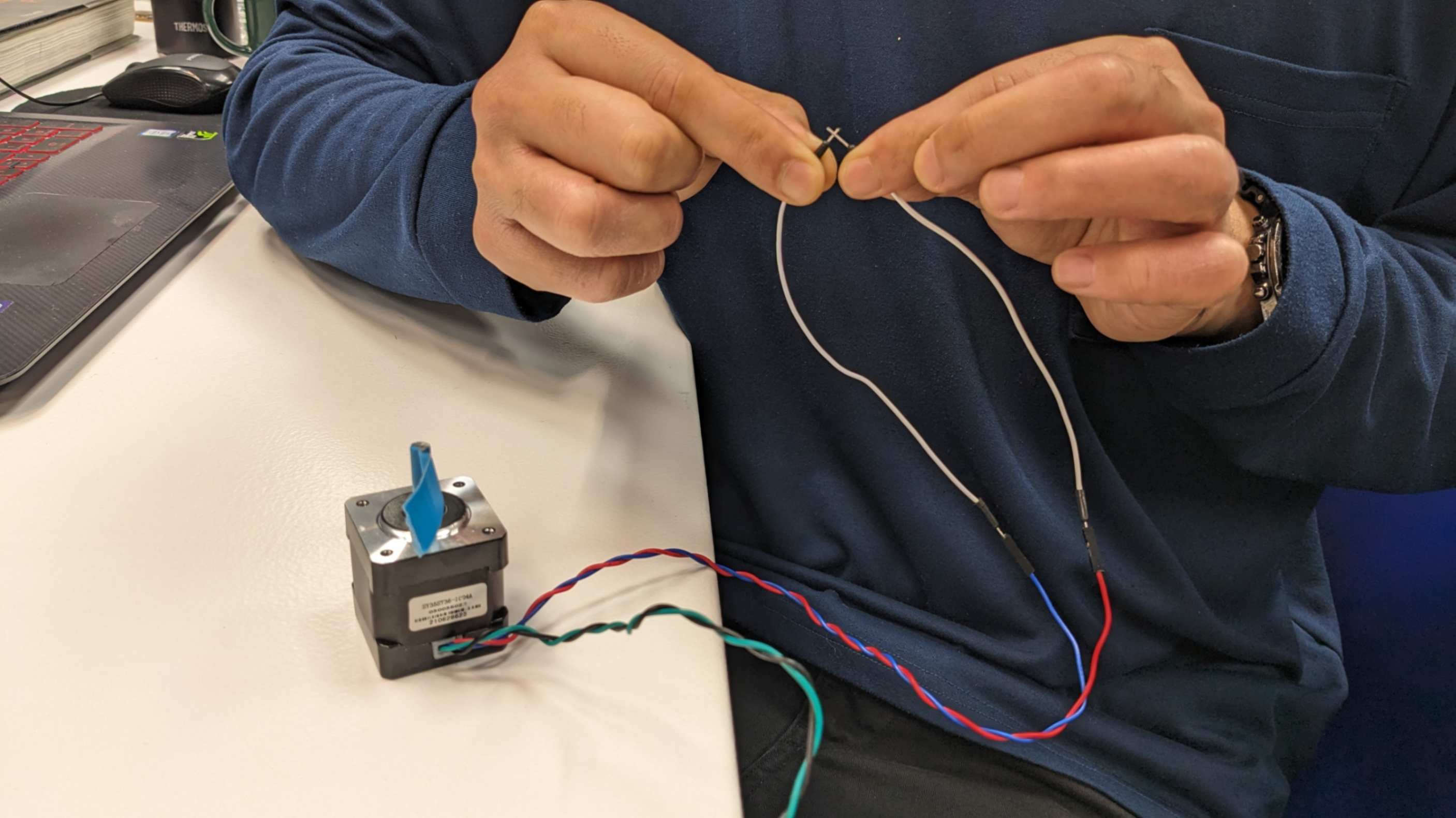
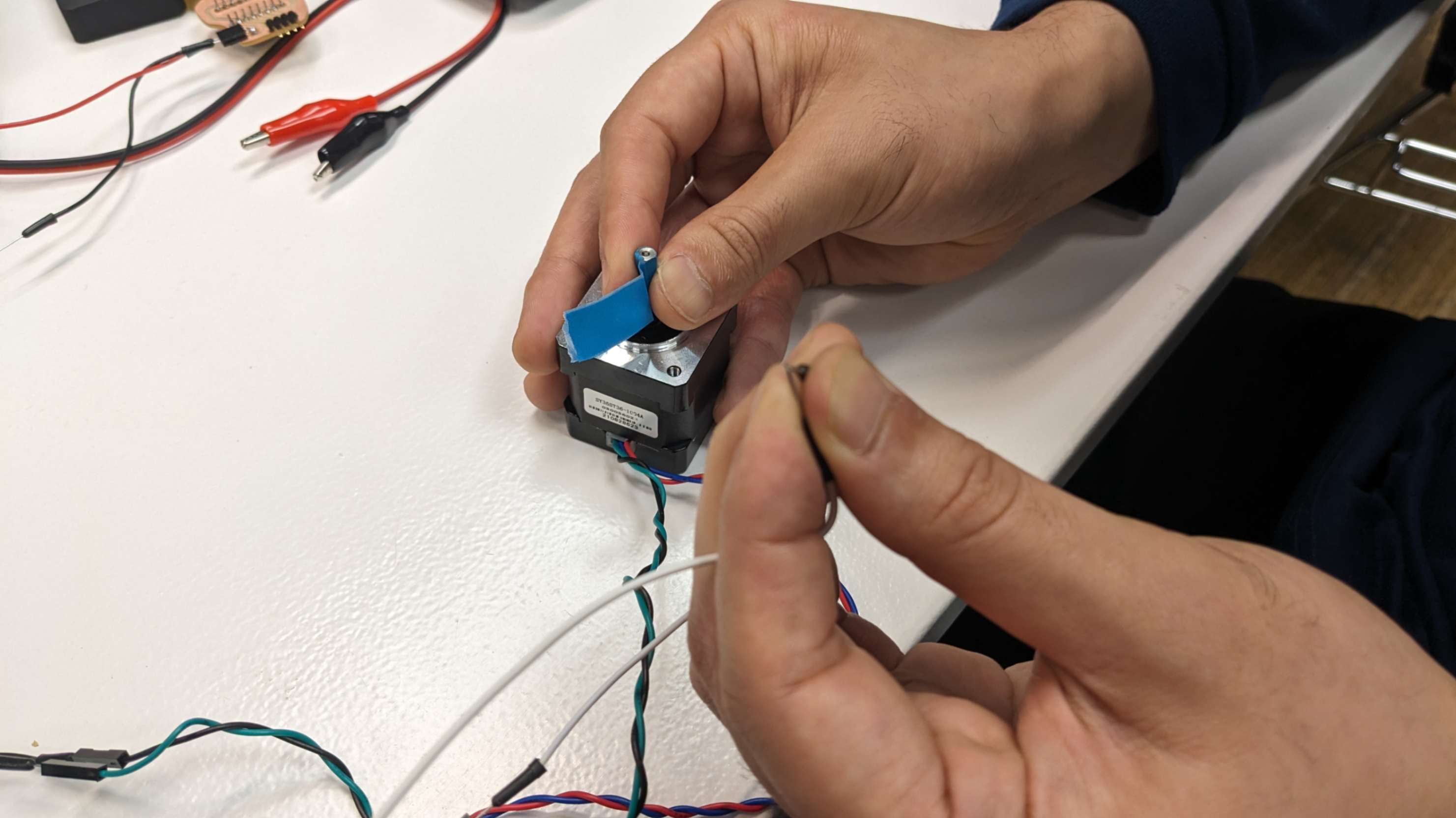
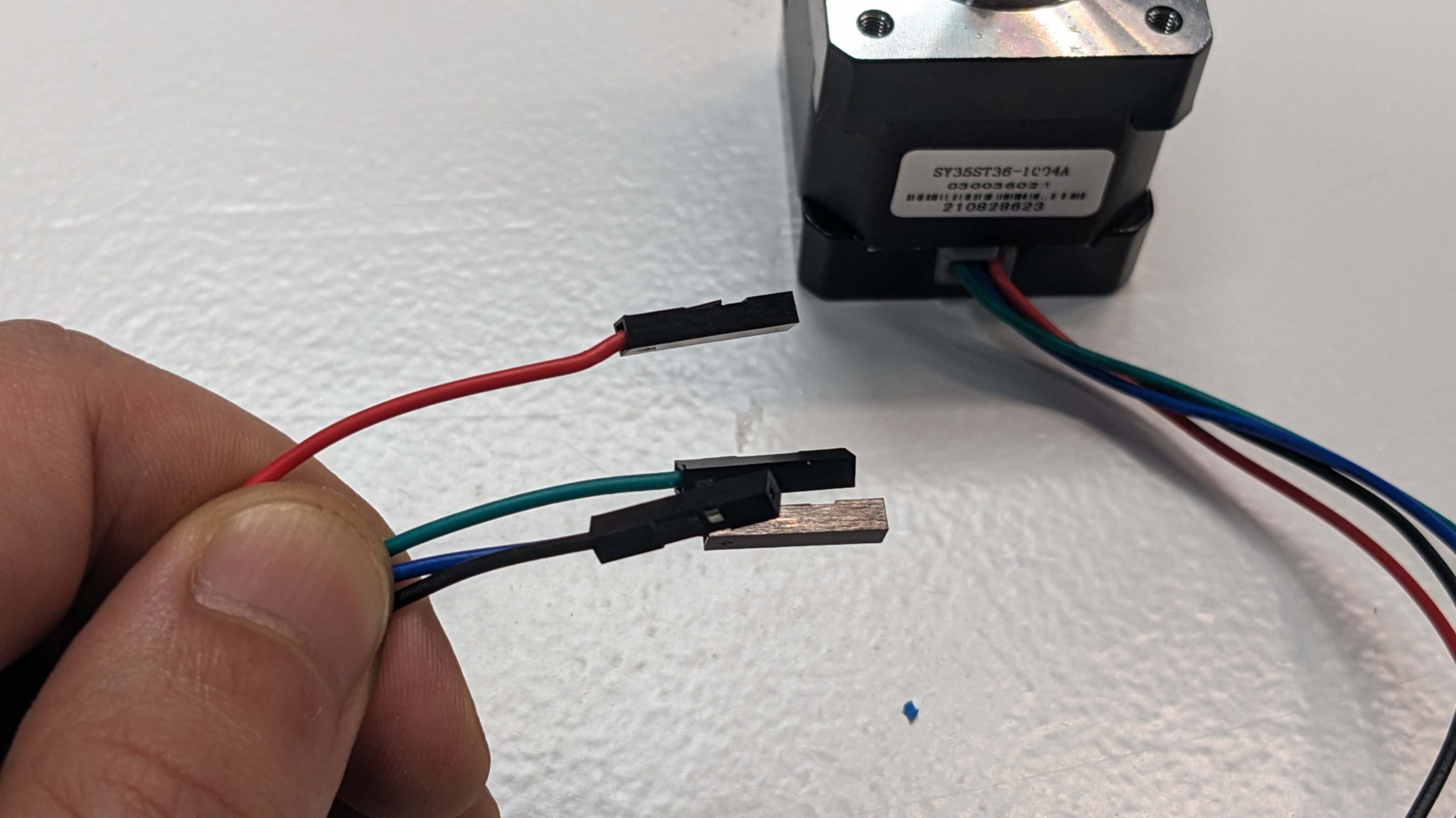
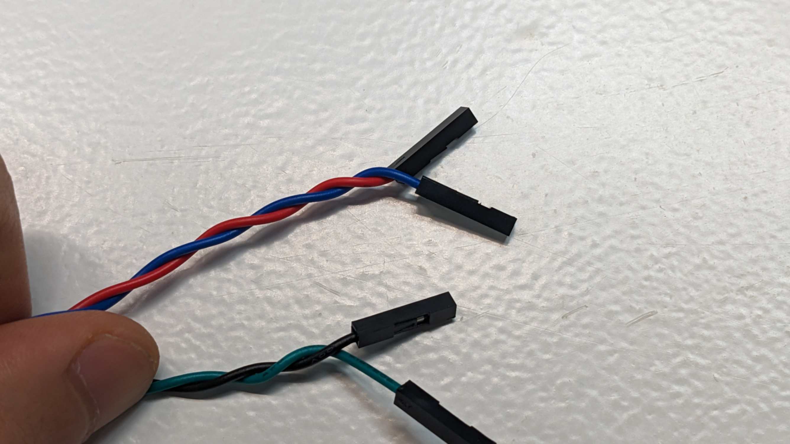
For the stepper motor, I needed to first check the phases. This can be checked by looking at the datasheet, but my tutor showed me a trick. The trick is to use a wire or pins that come out from the motor one by one while twisting the shaft. When the shaft becomes harder to twist, the connection is a phase. In my case, it was Blue & Red, and Black & Green.
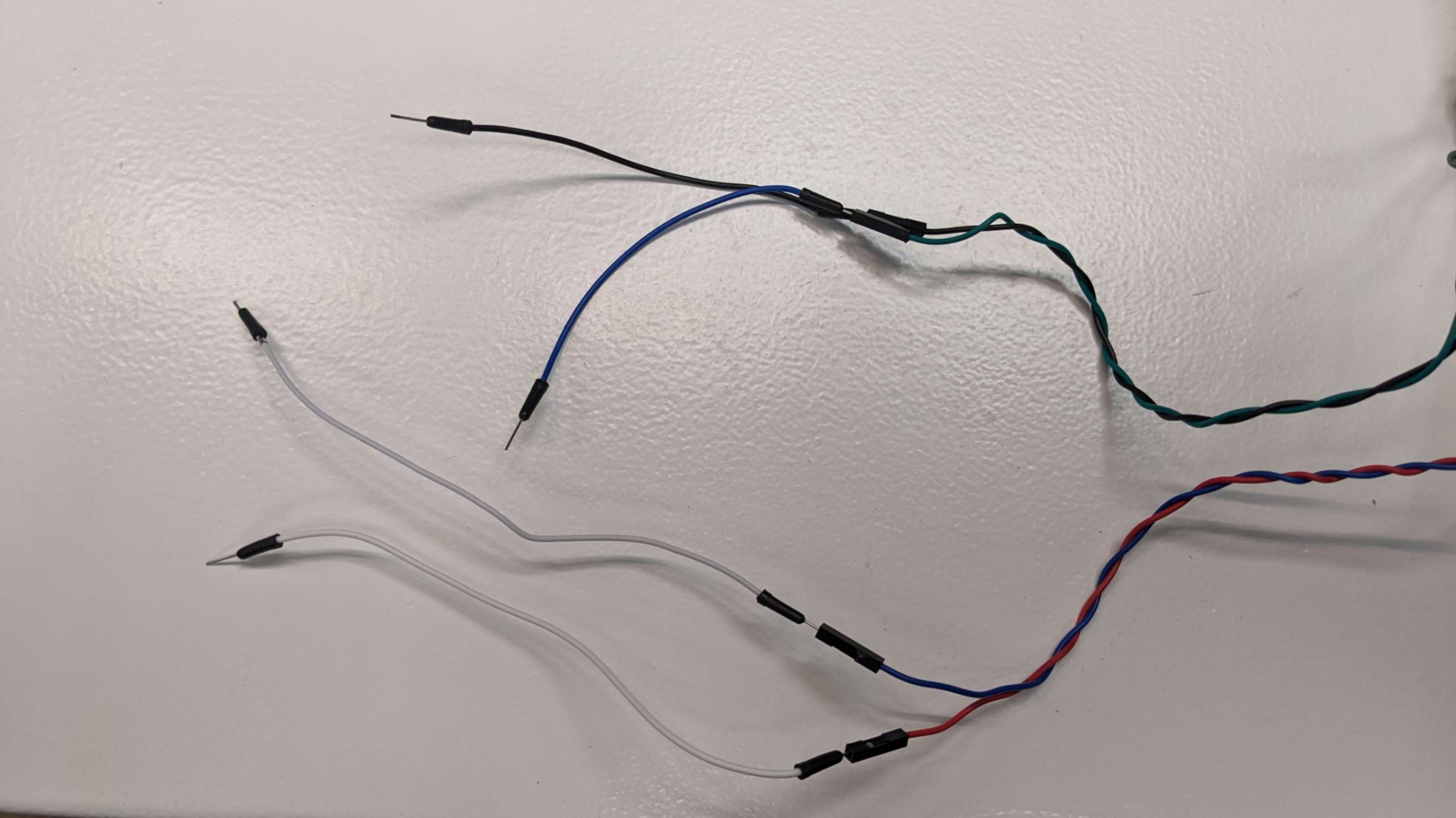
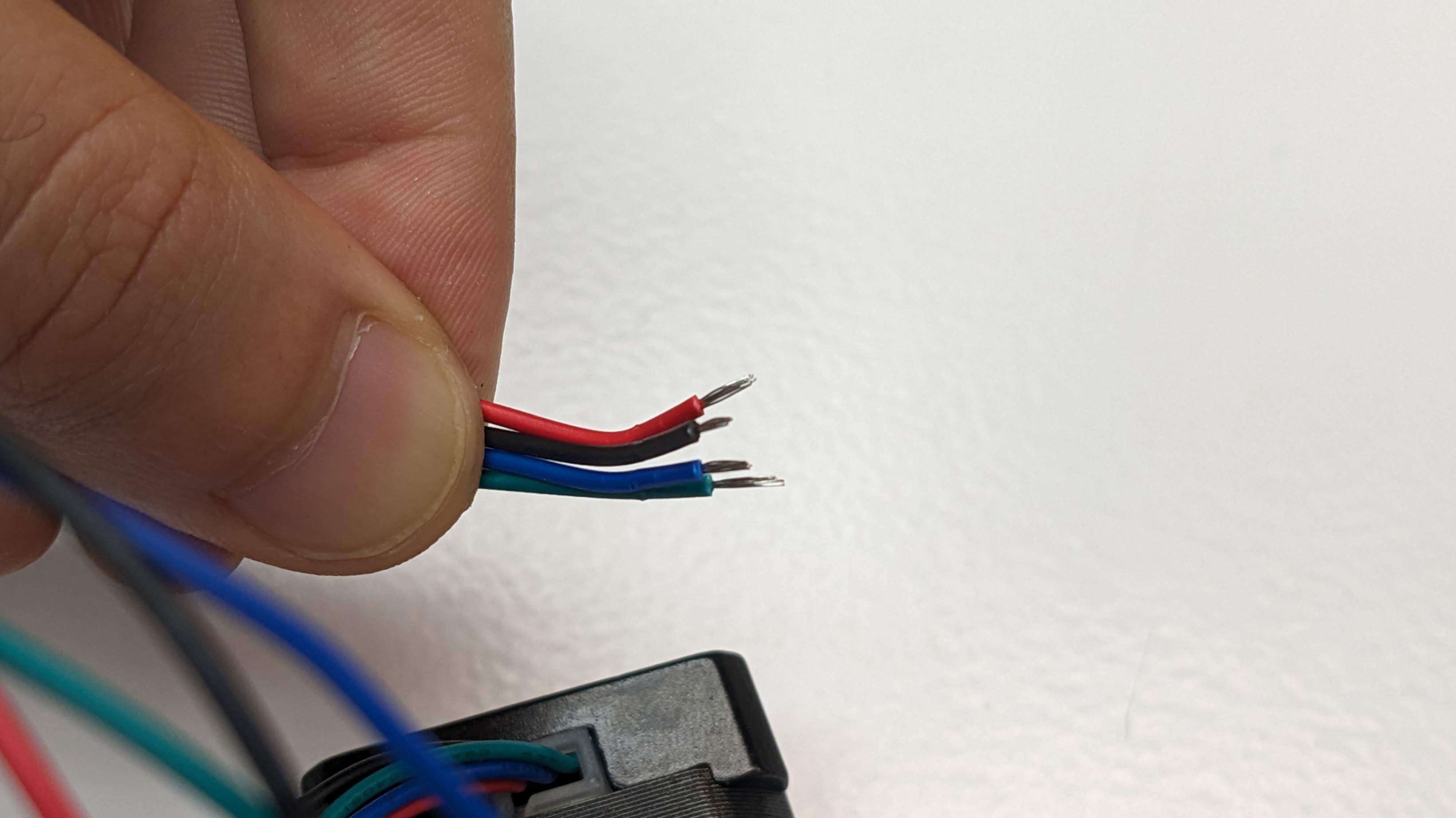
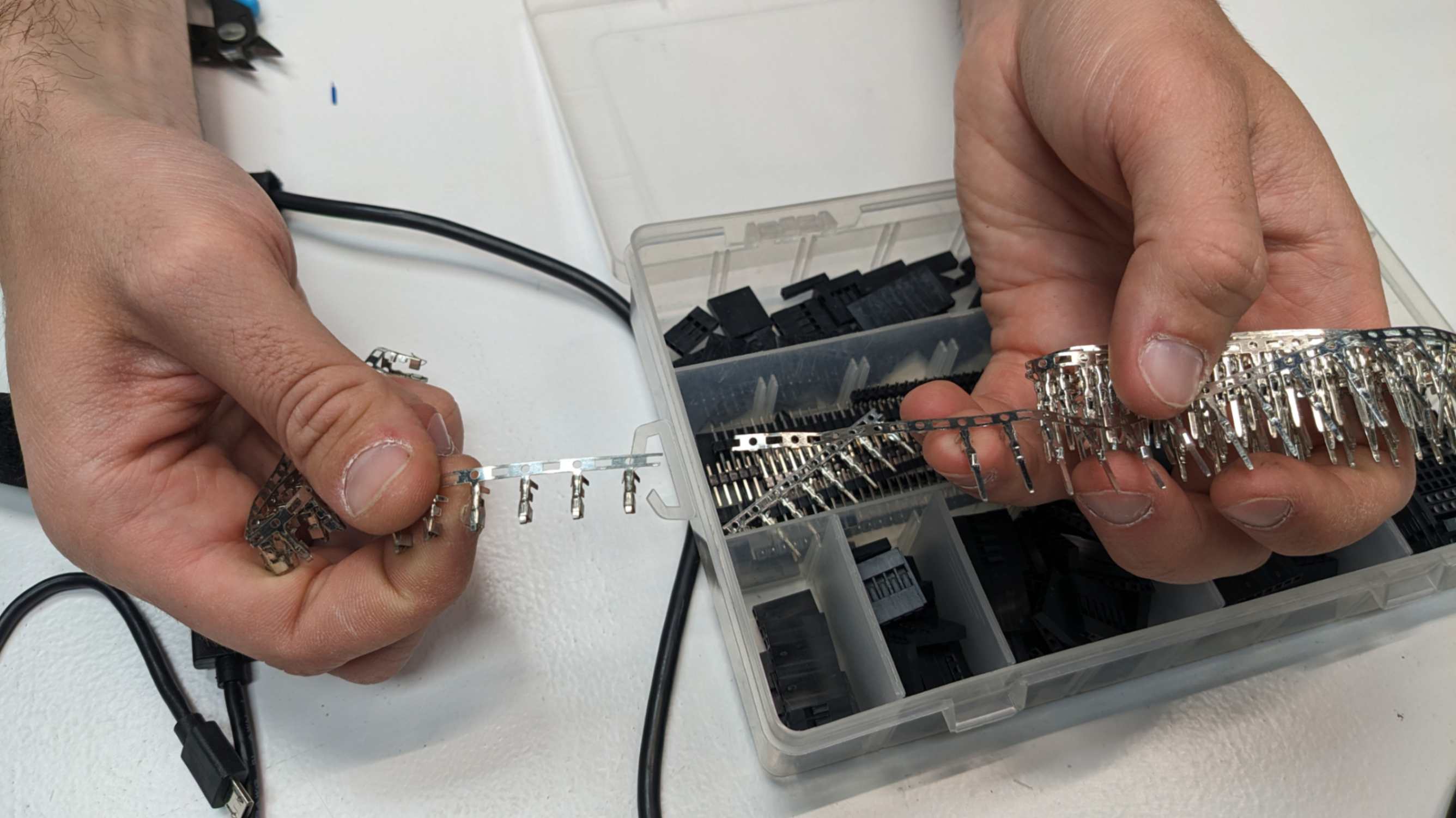
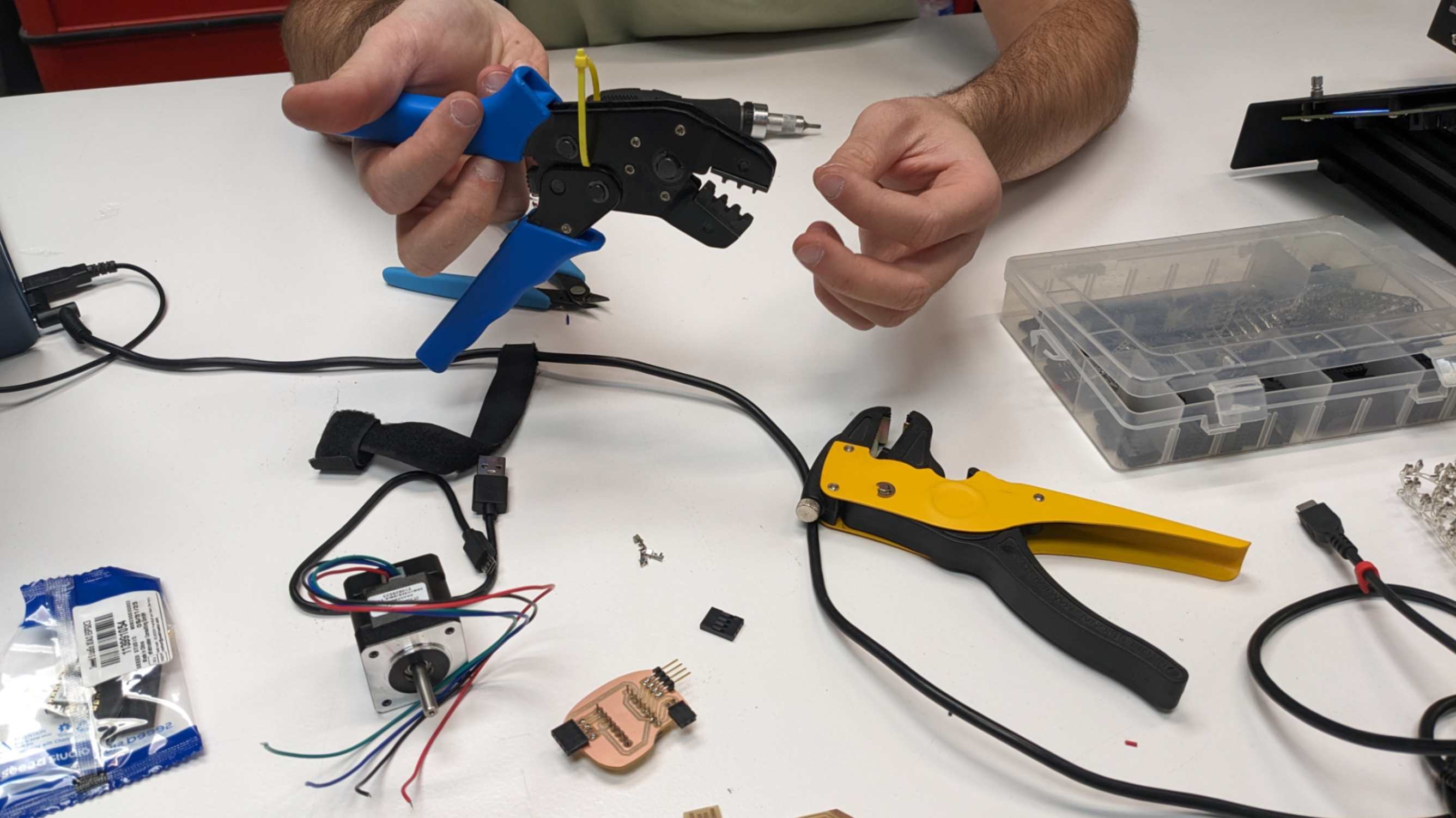
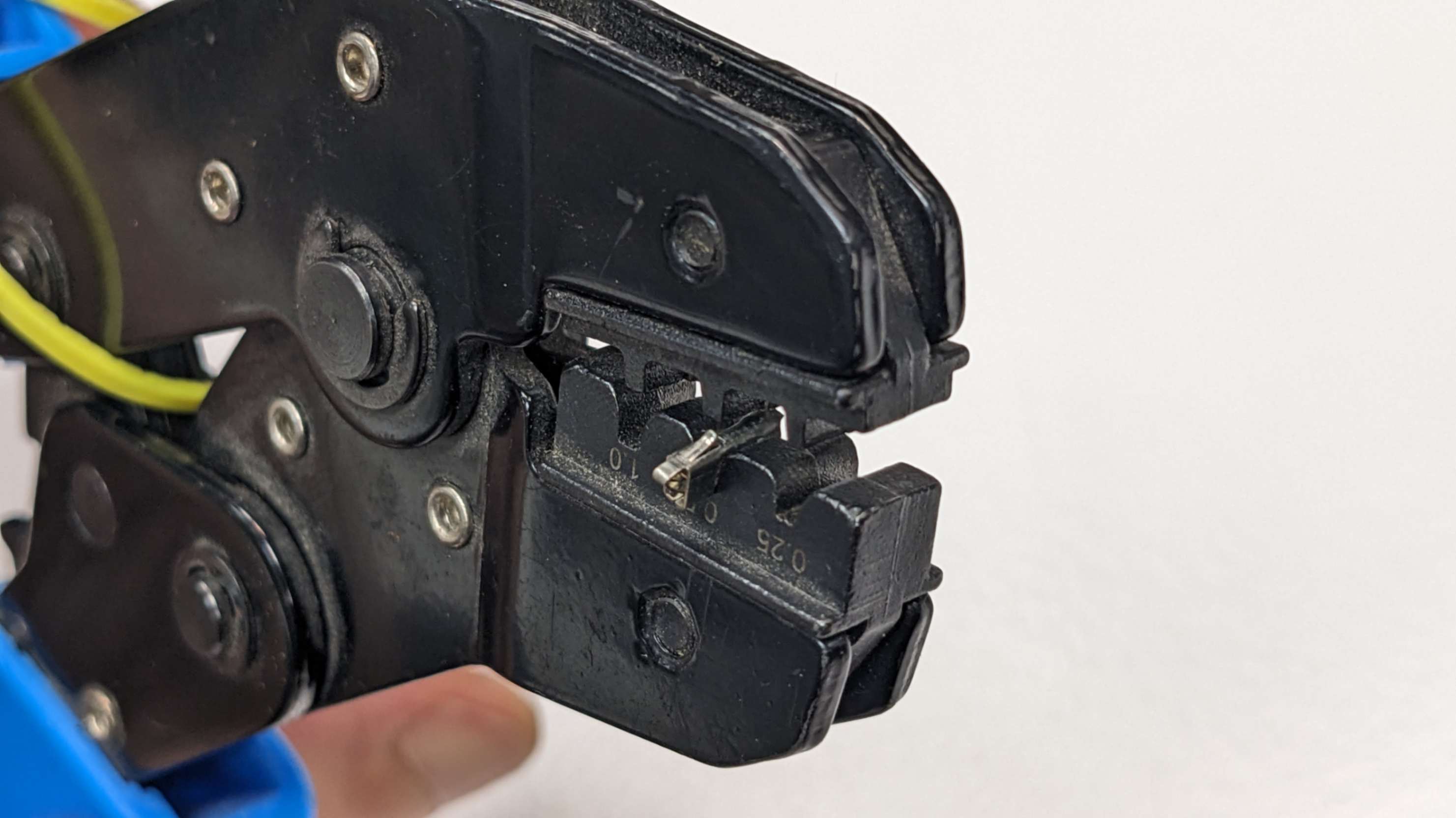
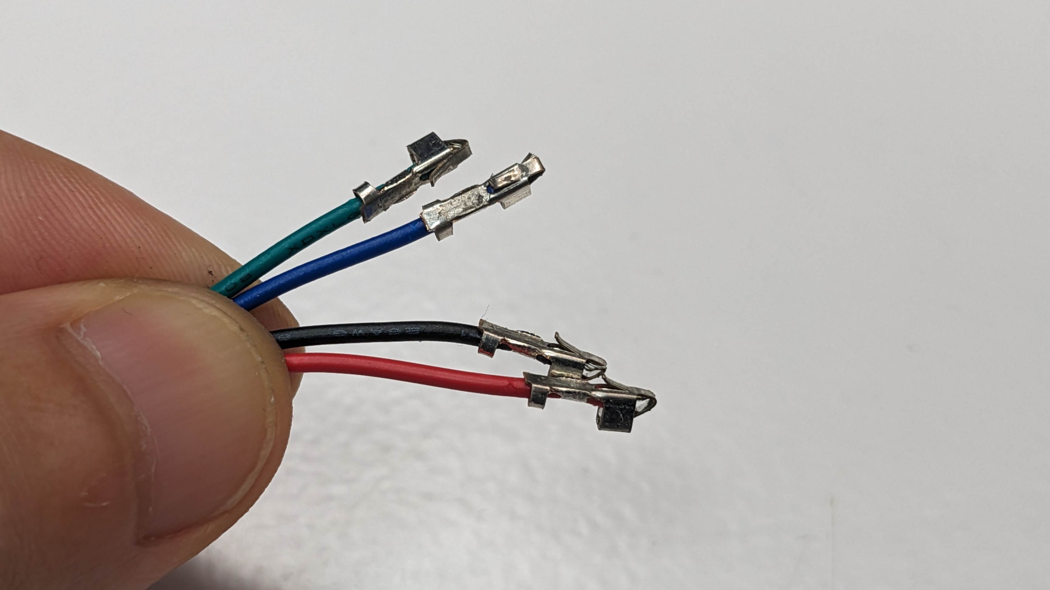
Then, I needed to attach female connectors to those wires, because those wires were new and did not have anything on their tip. The process of attaching the connector was simple but quite a hard task because it requires precision and concentration. At the end was able to attach female connectors to all the wires. After that, I simply connect this PCB with the development board, stepper motor, and power supply.
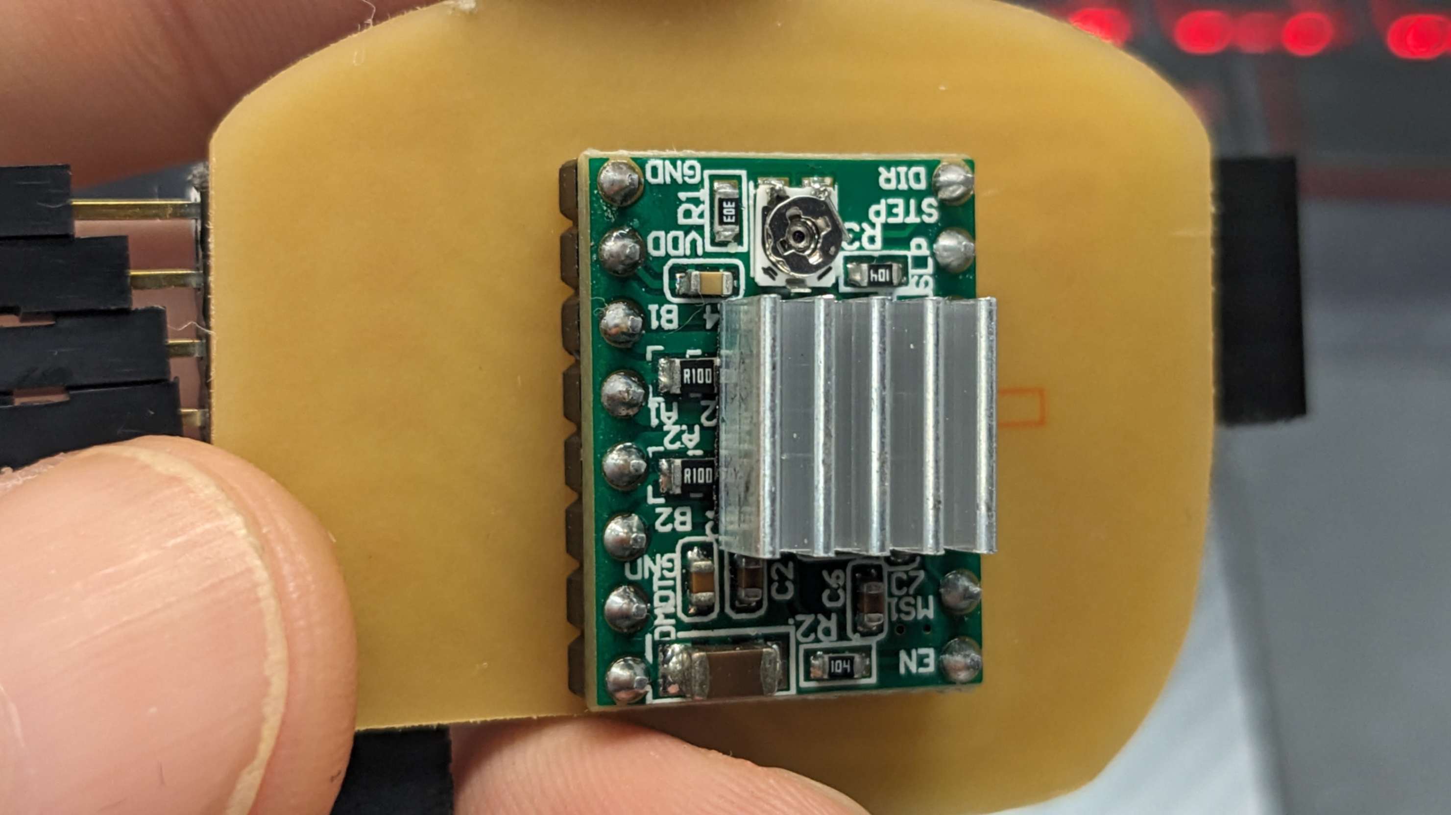
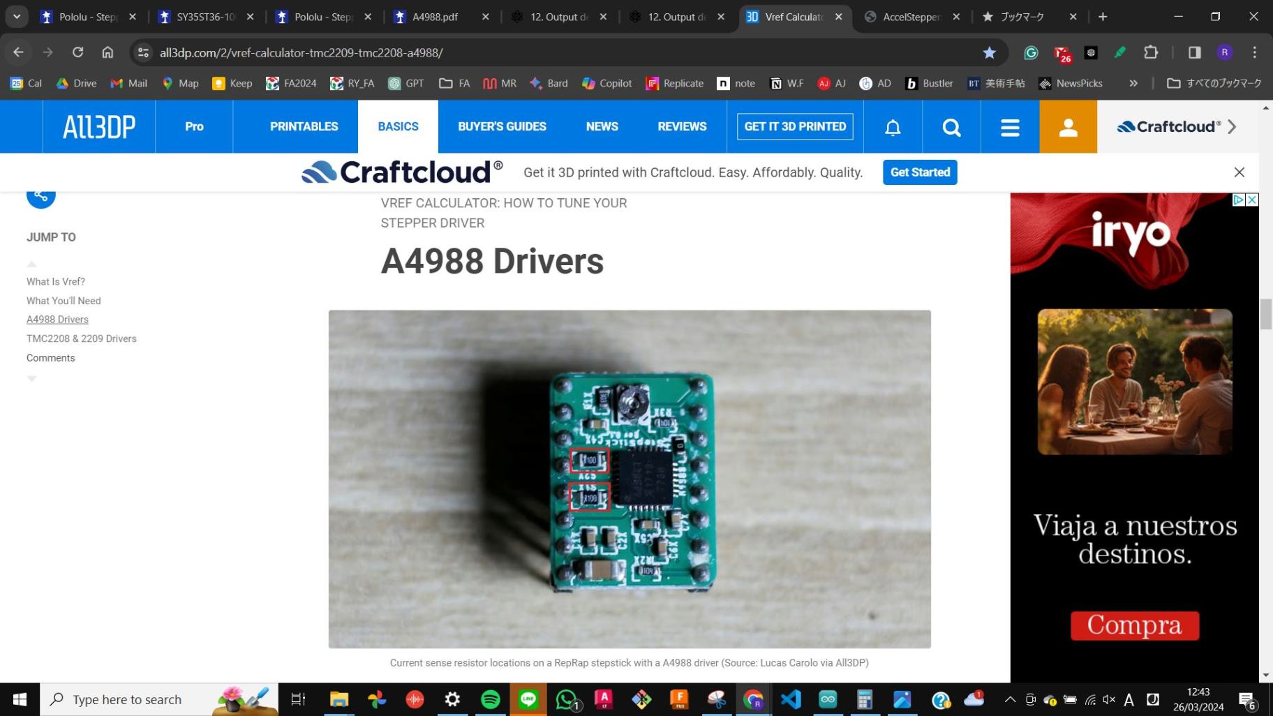
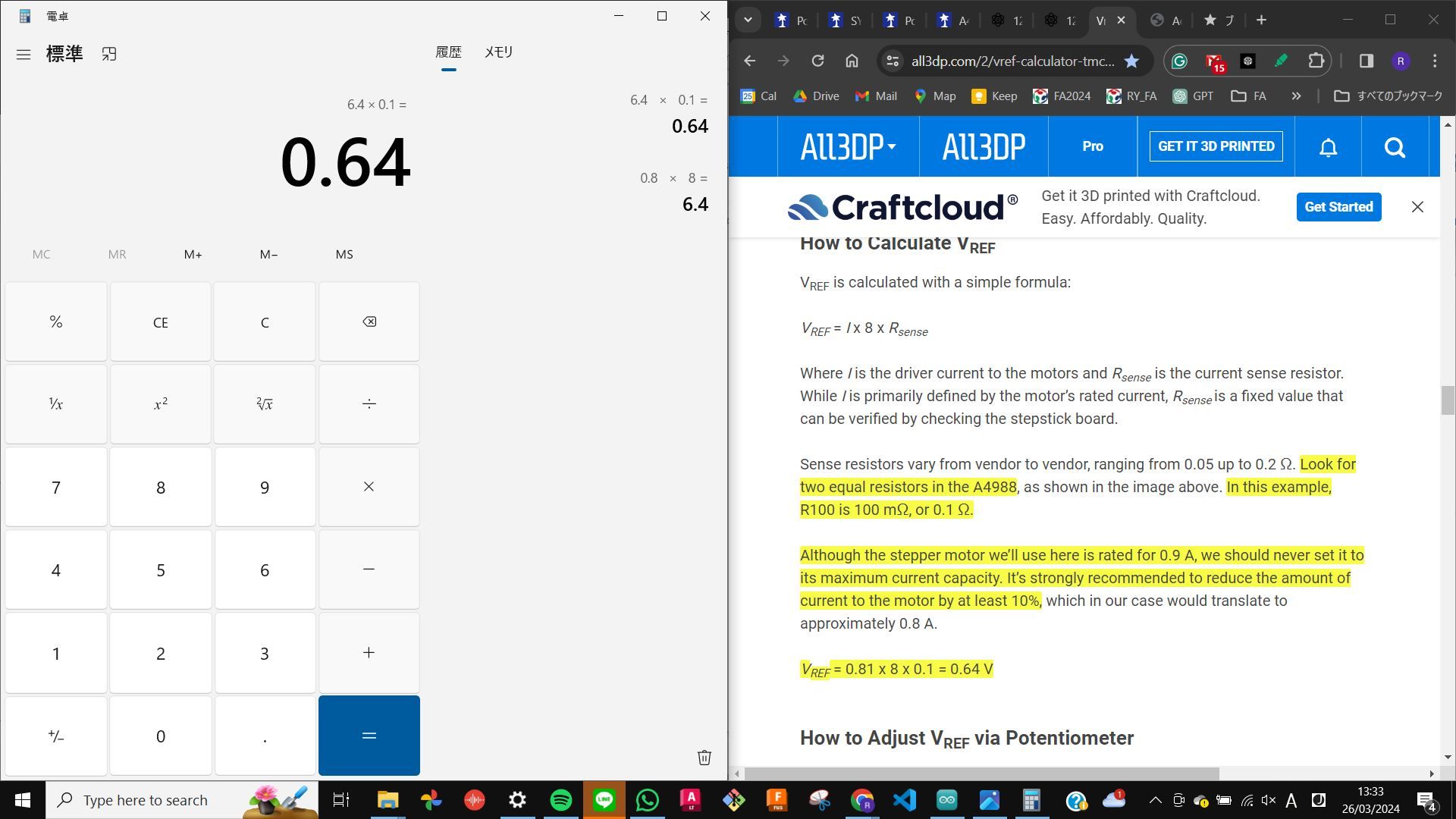
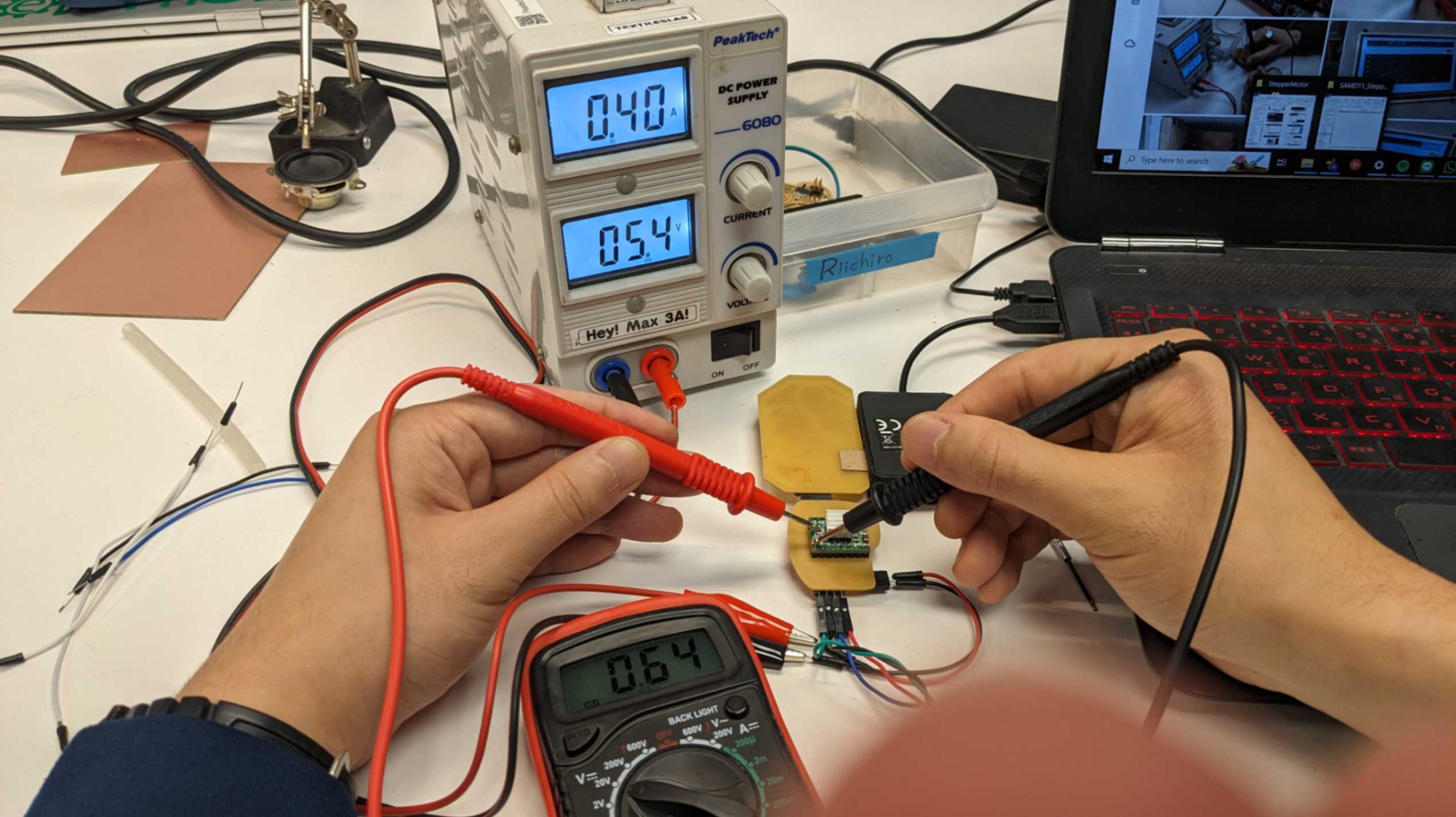
Adjustment on the motor driver
Before trying to move the motor I needed to adjust the Vref by twisting the screw on the motor driver while checking the current with a multimeter (use 200mA setting). The value is calculated by this equation. Vref = I x 8 x Rsense. Details are explained on this page. In my case, the value was 0.64, so I set the motor drivers to this value. Ideally, use a non-conductive tool to do this step.
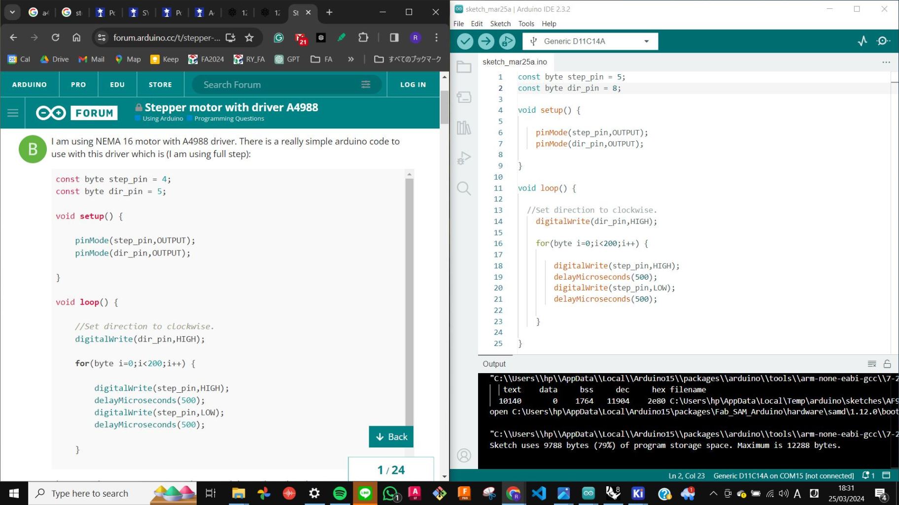
For programming, I found a code on
this page
And then my tutor helped me to adjust the code for quick testing.
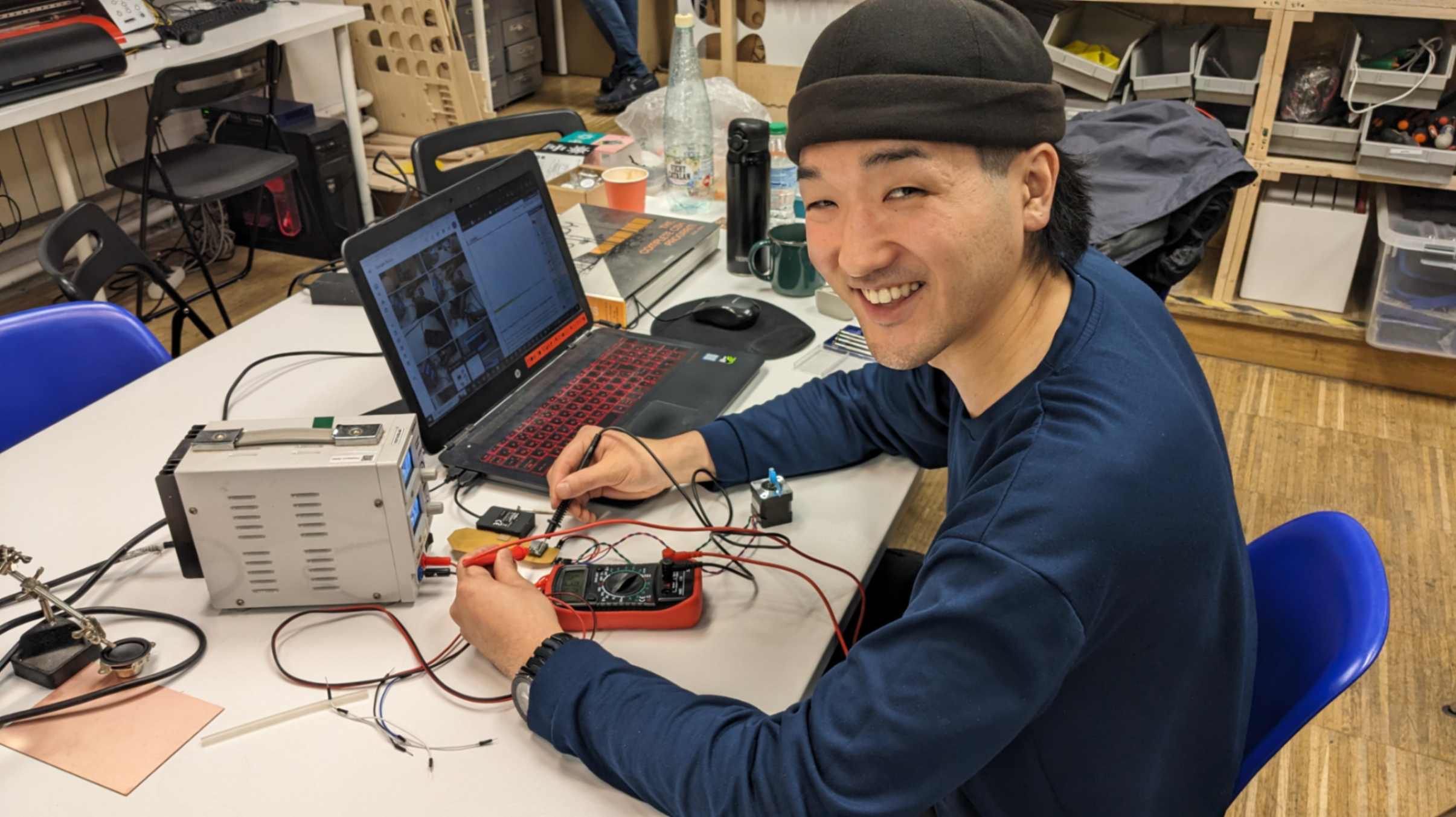
Finally, I was able to move the stepper motor!!!
Video(.mp4)
W9_Moving Stepper Motor_FA2024RY_compress.mp4


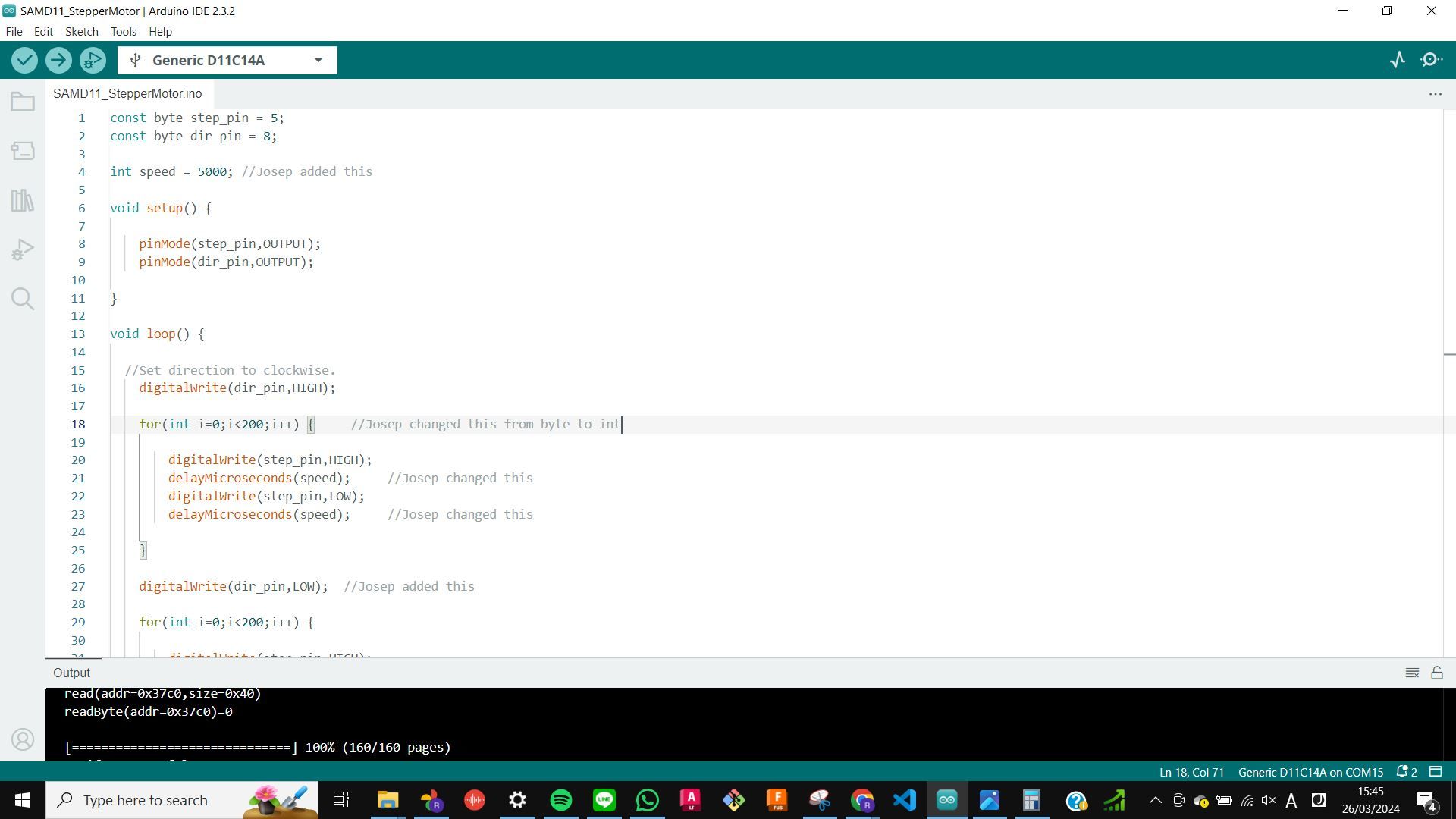
              const byte step_pin = 16;
              const byte dir_pin = 17;

              int speed = 100; //Josep added this

              int steps = 1000;

              void setup() {

                  pinMode(step_pin,OUTPUT);
                  pinMode(dir_pin,OUTPUT);

              }

              void loop() {

                //Set direction to clockwise.
                  digitalWrite(dir_pin,HIGH);

                  for(int i=0;isteps;i = i+1) {     //Josep changed this from byte to int

                      digitalWrite(step_pin,HIGH);
                      delayMicroseconds(speed);     //Josep changed this
                      digitalWrite(step_pin,LOW);
                      delayMicroseconds(speed);     //Josep changed this

                  }

                  digitalWrite(dir_pin,LOW);  //Josep added this

                  for(int i=0;isteps;i++) {

                      digitalWrite(step_pin,HIGH);
                      delayMicroseconds(speed);    //Josep changed this
                      digitalWrite(step_pin,LOW);
                      delayMicroseconds(speed);    //Josep changed this

                  }

              }
Problem
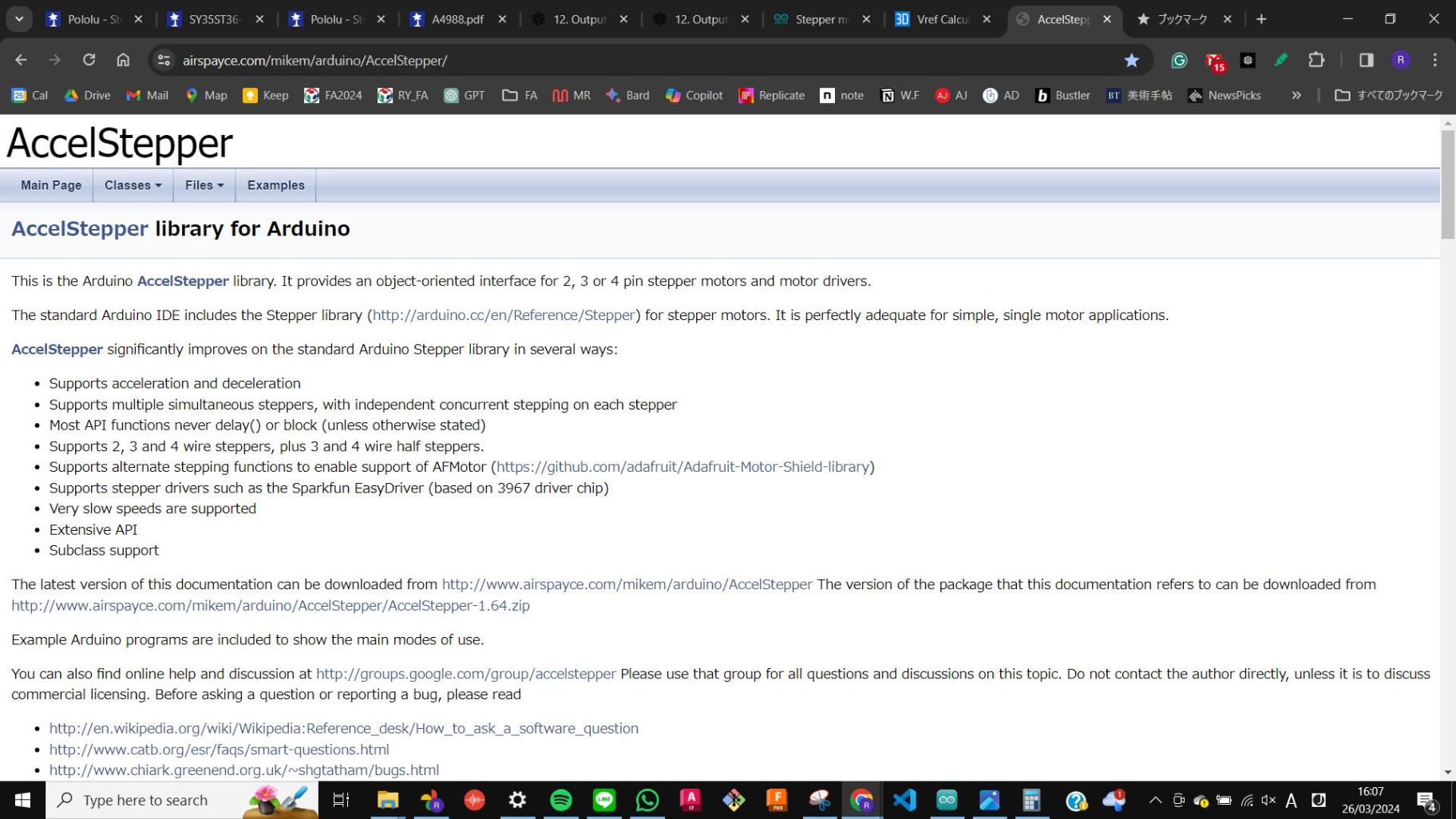
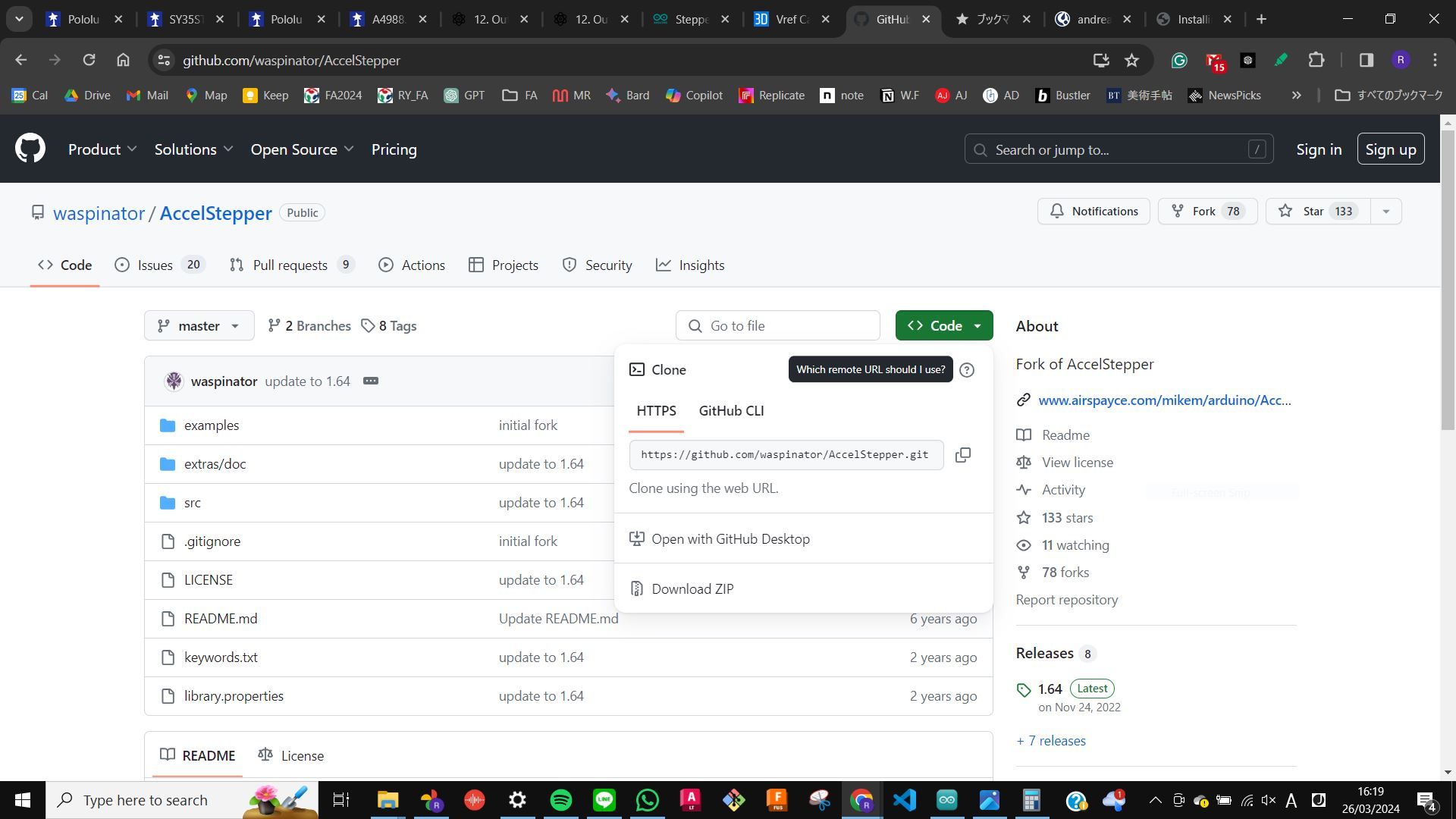
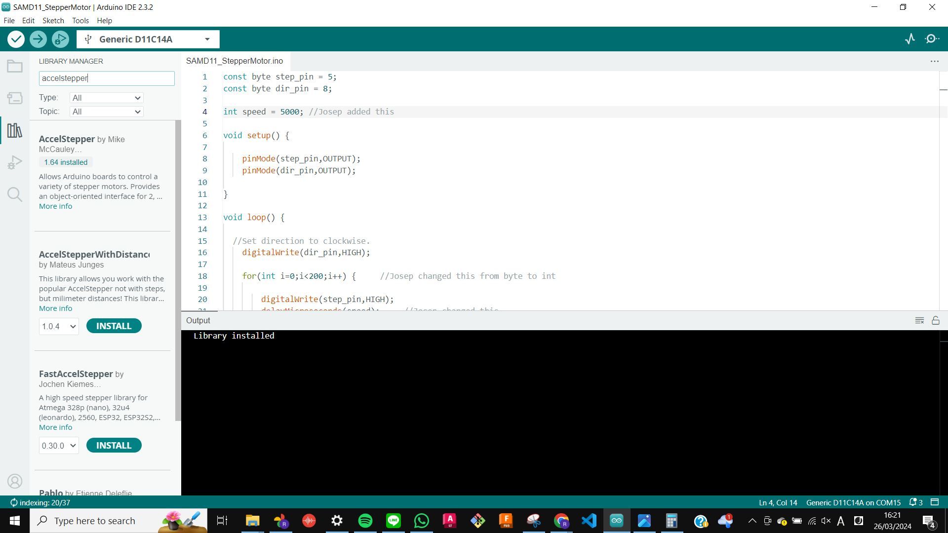
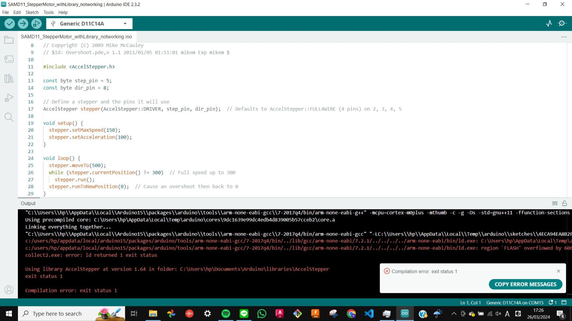
My tutor advised me to use a library called AccelStepper to fully control stepper motors, however since SAMD11 does not have much memory I was not able to upload the code with the library. Therefore I decided to use SAMD21 for more exploration in Week11 Input
Thank You Always
Special thanks to my tutor Josep for patiently dealing with me as always.