Week 11
Input Device
Fab Academy 2024
Riichiro Yamamoto
- Group Assignment
- SAMD21
- Capacitive Touch Pin (or PTC)
- Thinner Footprint on KiCAD
- D+ D-
- DJ Potentiometer
- SAMD21 ver 2.0
- 3 Stepper Motors Board
- Reading Potentiometer
- Step Without Delay
- Step Without Delay + Potentiometer
- Step Without Delay + Potentiometer + 3 Stepper Motors
Dear My Friend
This week I got introduced to input device. They are basically sensors that detect all sorts of different value from the real world. This week is very important week for my final project since my final project is heavy on input device. For this week I started to make 1st iteration of my final project such as DJing with 3D printer. I am aiming to take the result of this week and develop it through spiral development.
Hope you enjoy
Riichiro Yamamoto
Group Assignment
this week's group assignment was to probe an input device's analog levels and digital signals.
Here is the link to the group assignment page

SAMD21
Since I had a problem uploading the AccelStepper library to SAMD11 due to small memory, I started this week by making a new development board with SAMD21.
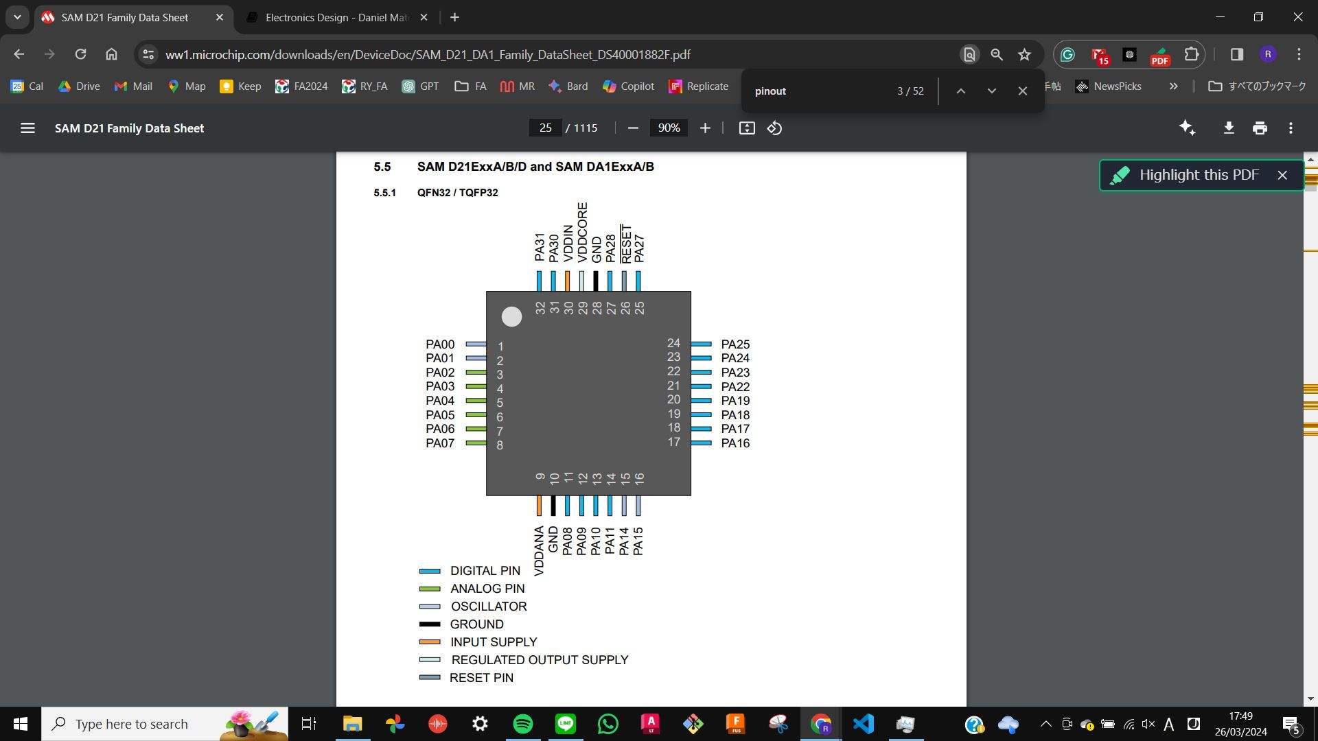
I used SAMD21E17A. As always I started the process by looking at the datasheet, and pinout. As references, I used
SAMD21E17/E18 devkit board by Quentin Bolsee,
SAMD21E piano and synthesizer by Quentin Bolsee,
and Neil’s example from
Week6 embedded programming,
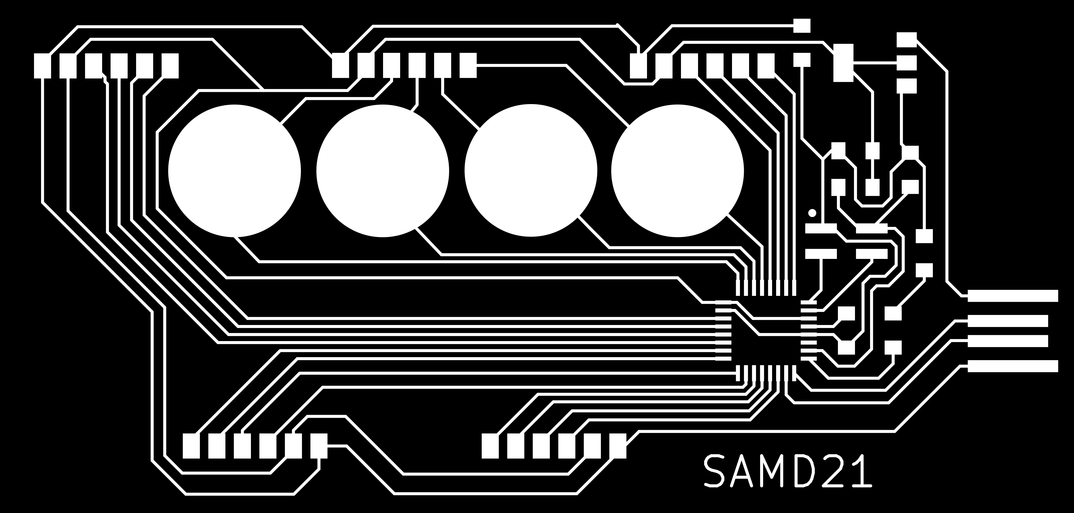
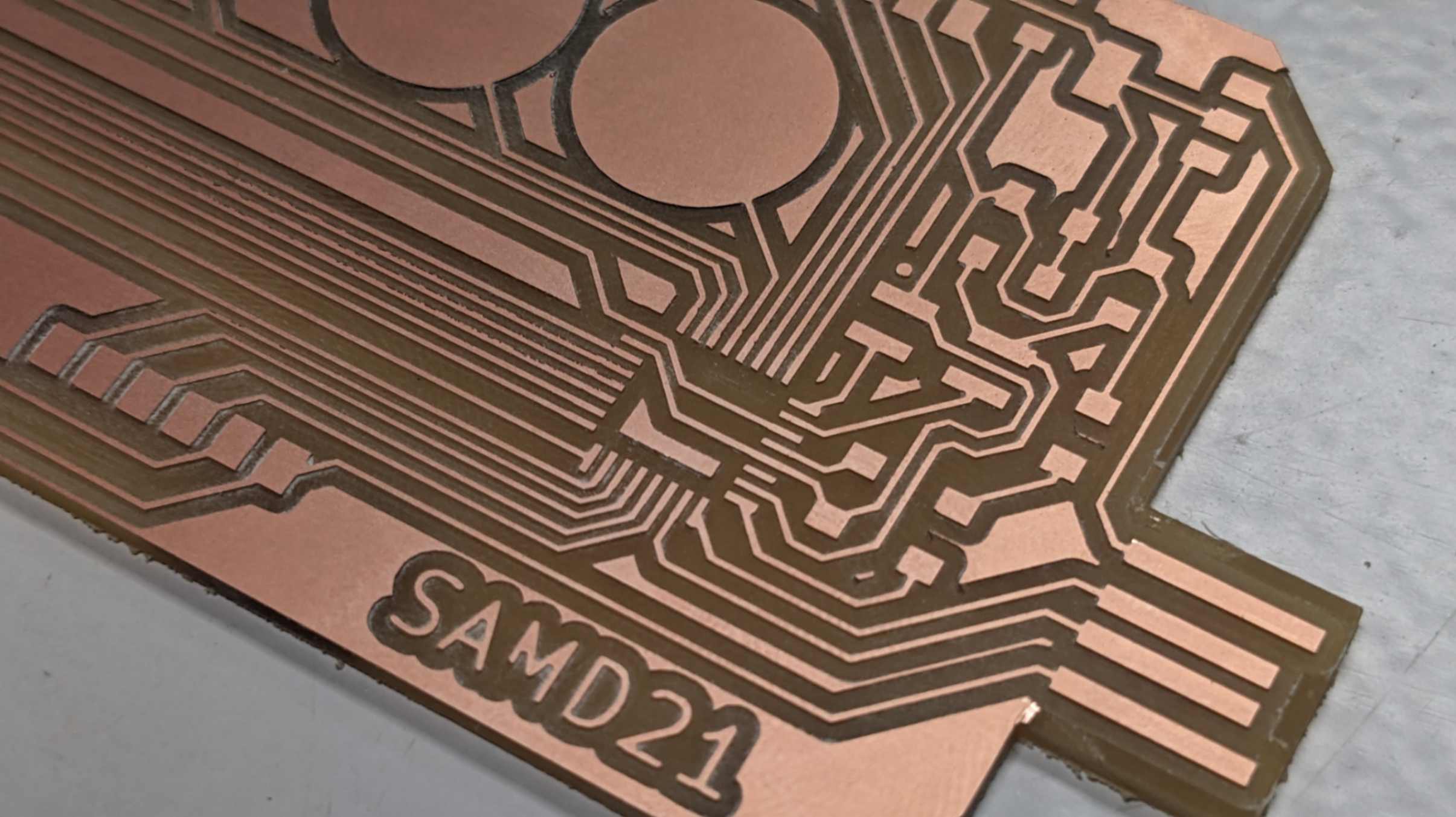
As a design concept, I wanted my PCB to have a capacitive touch function and maximum pins out for external connection.
Files
SAMD21.kicad_pro
SAMD21.kicad_sch
SAMD21.kicad_pcb
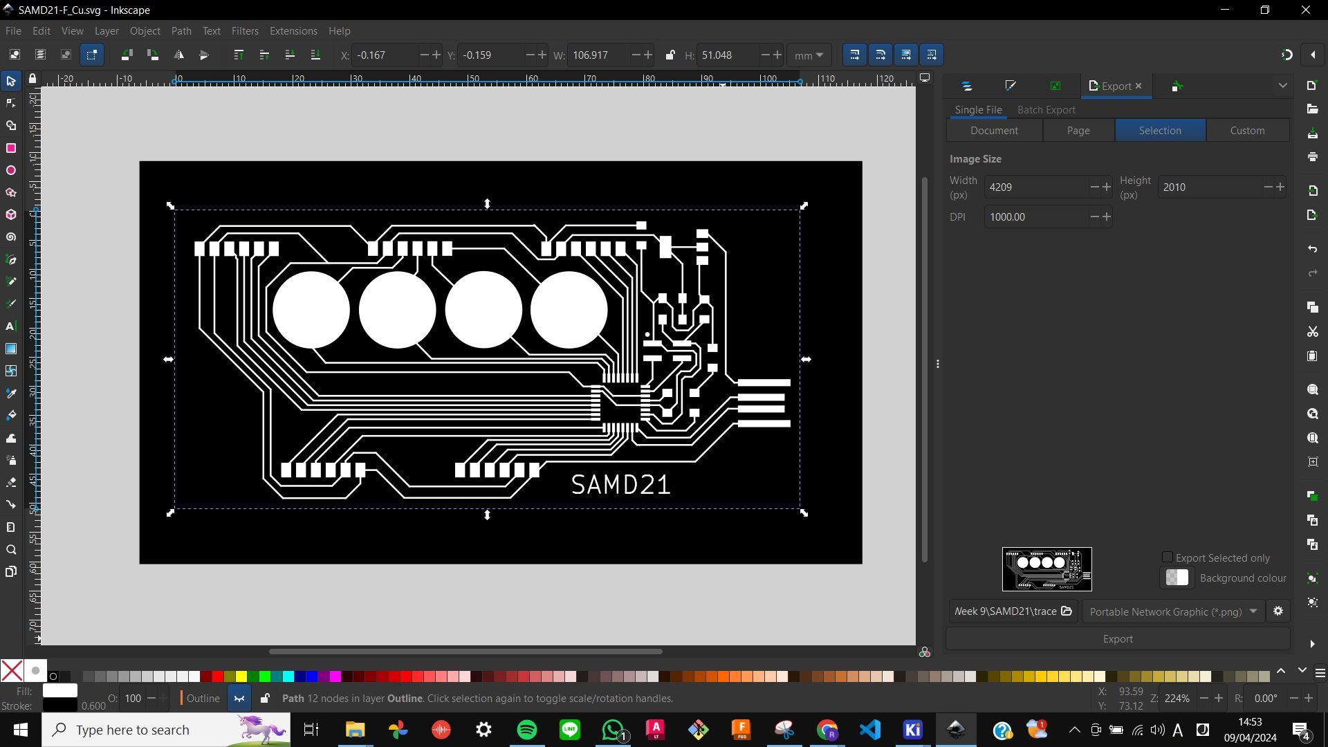
SAMD21-F_Cu.svg
outline.png
trace.png
outline.png.rml
trace.png.rml
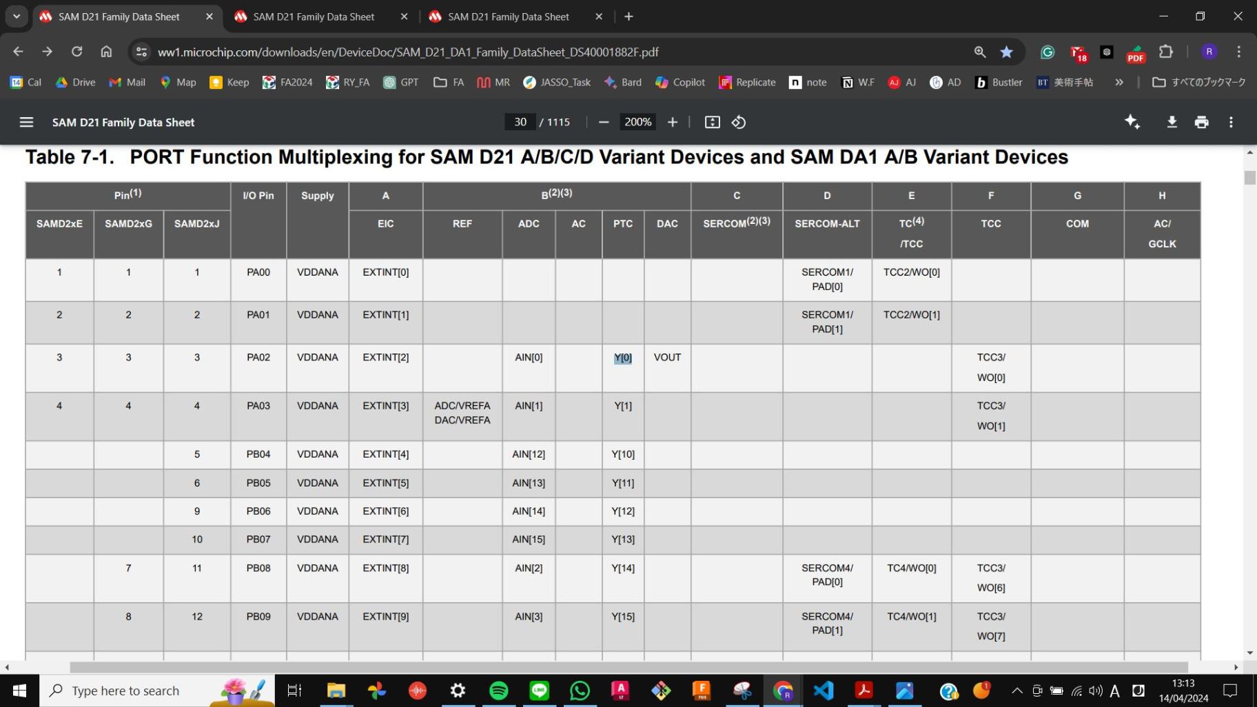
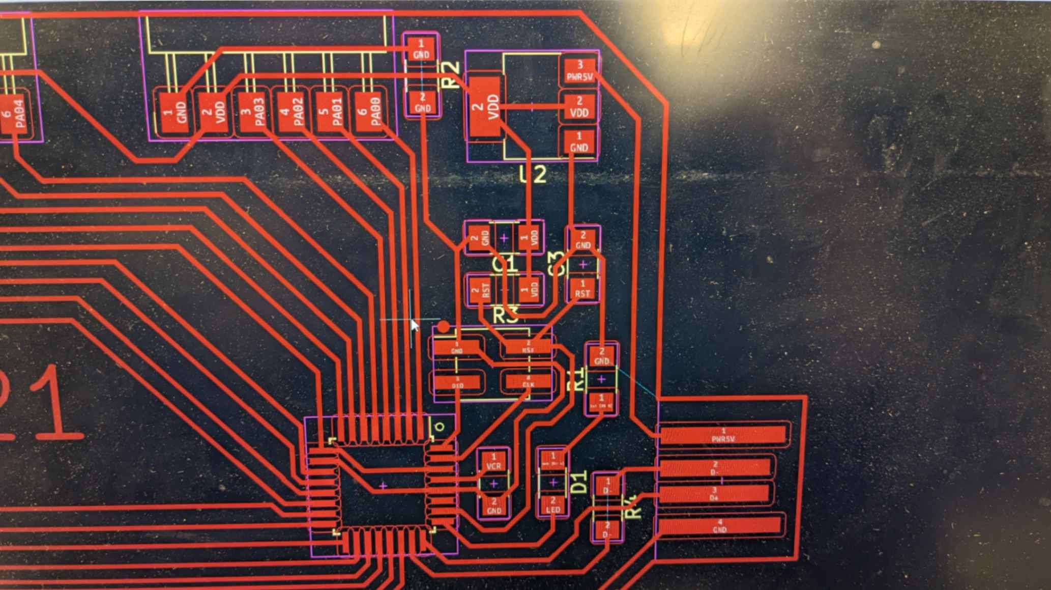
Capacitive Touch Pin (or PTC)
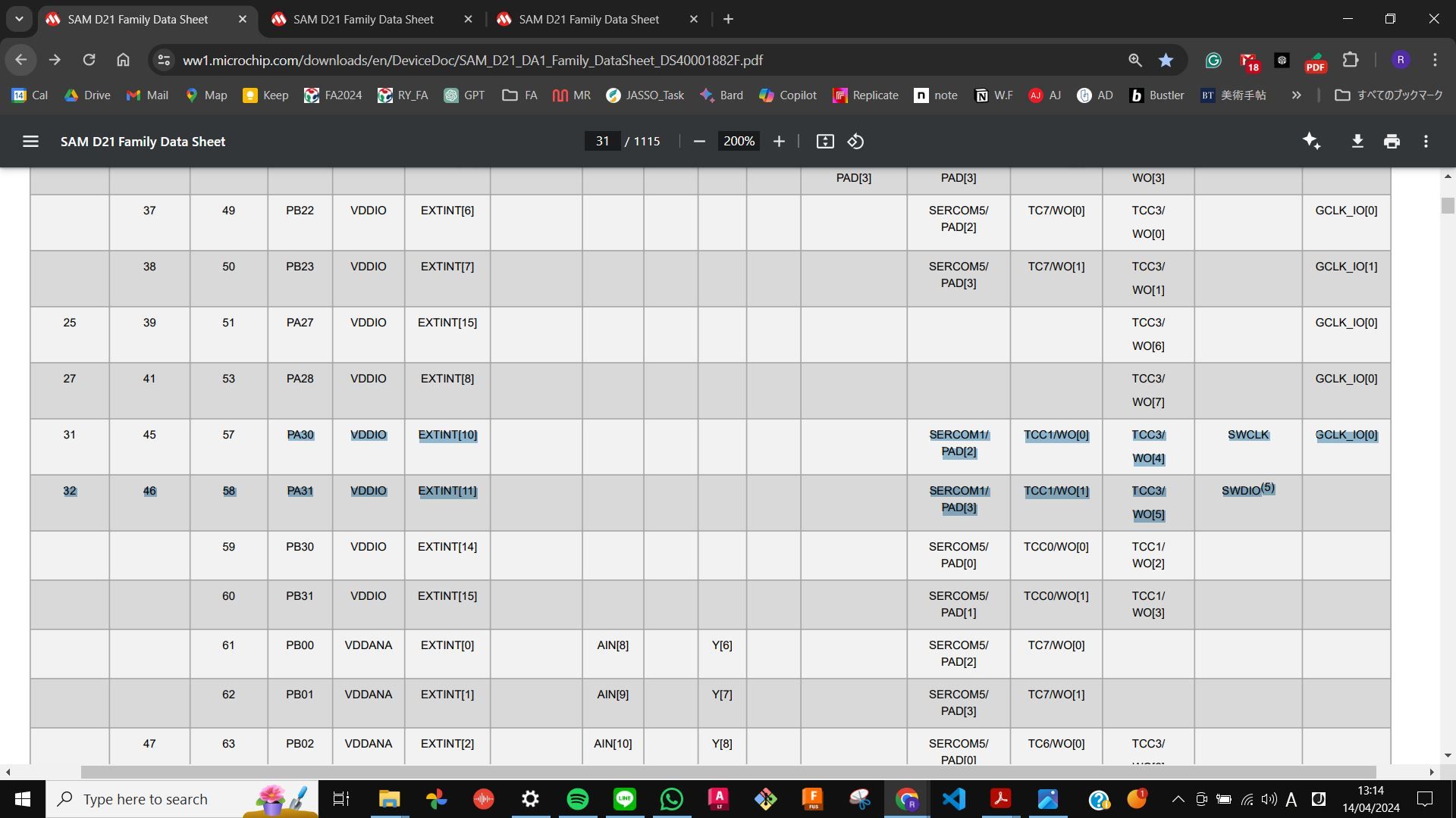
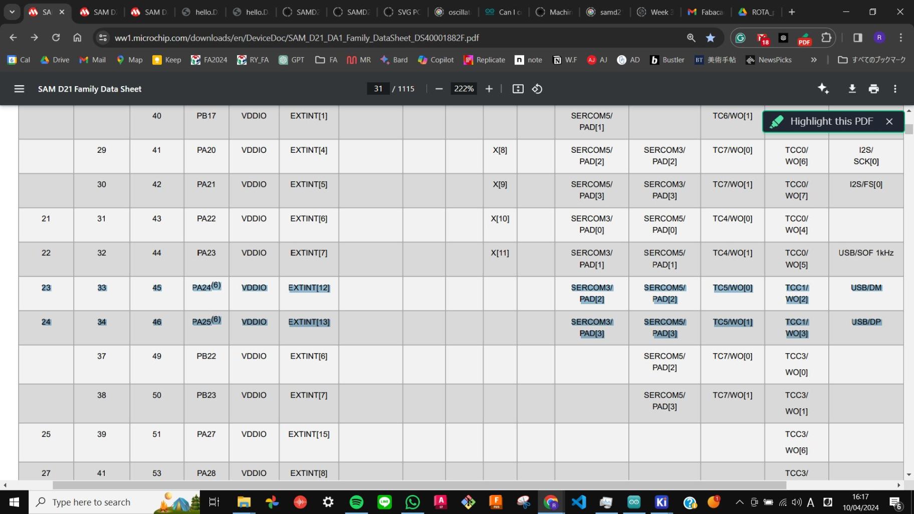
At first, I thought anypin works with capacitive touch but then my classmate told me that only specific pins have the capability. After researching it, I found out that it is explained in the SAMD21 datasheet in the Peripheral Touch Controller (PTC) section. PTC pins are shown in the table of I/O Multiplexing and Considerations. If a pin has X or Y in the PTC column, it should work with capacitive touch.
Later, I also found out which pin should be connected to DIO and CLK by looking at the table of I/O Multiplexing and Considerations.
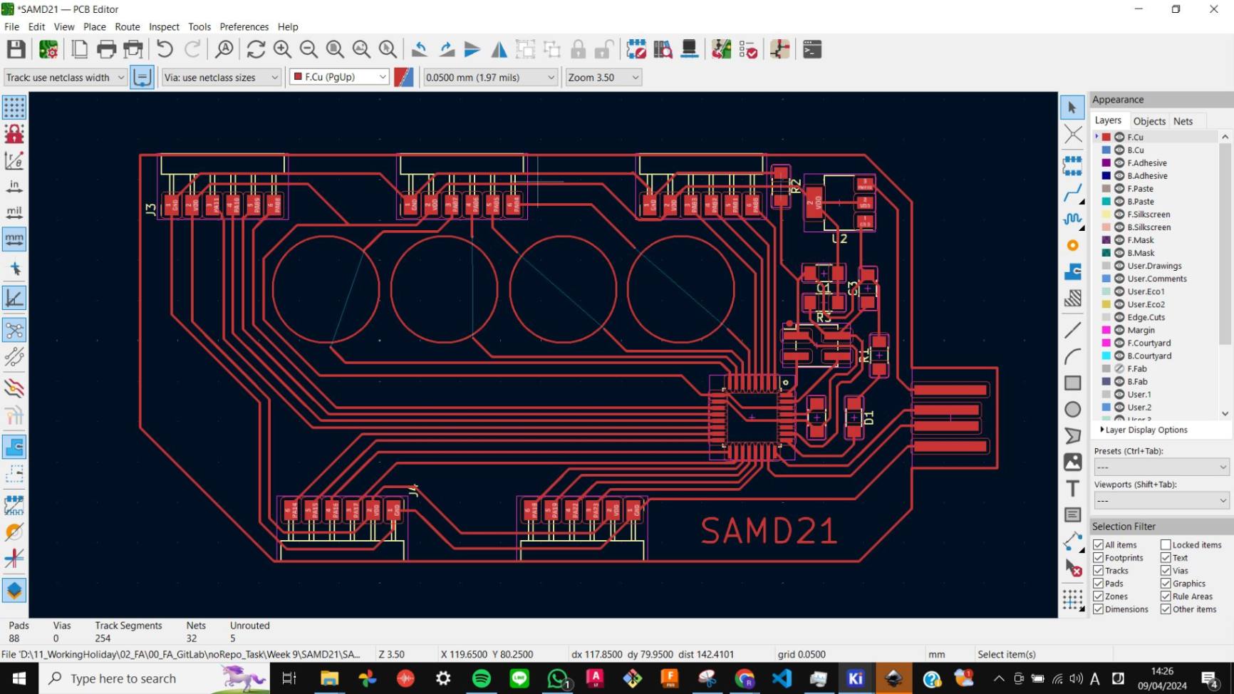
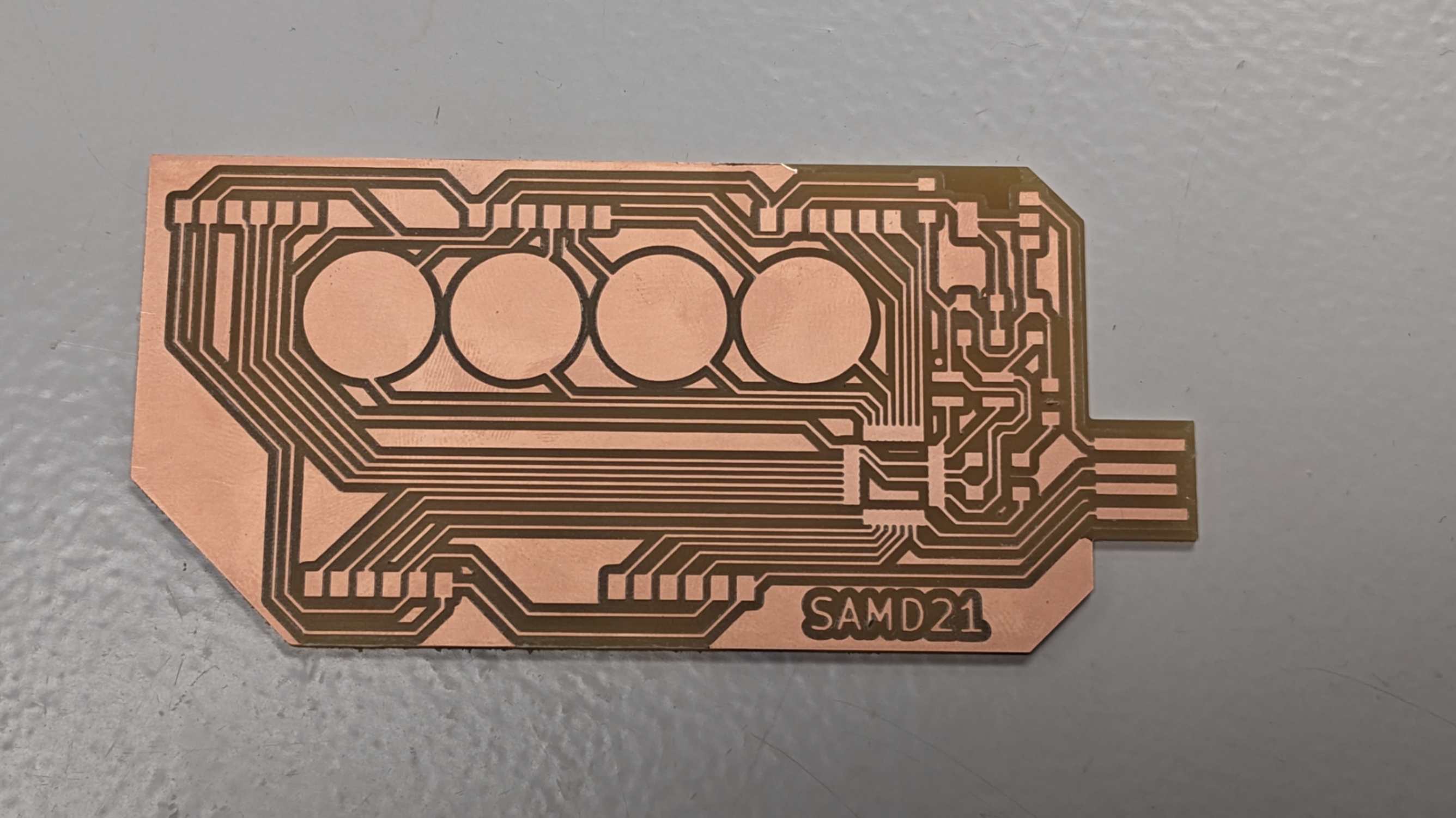
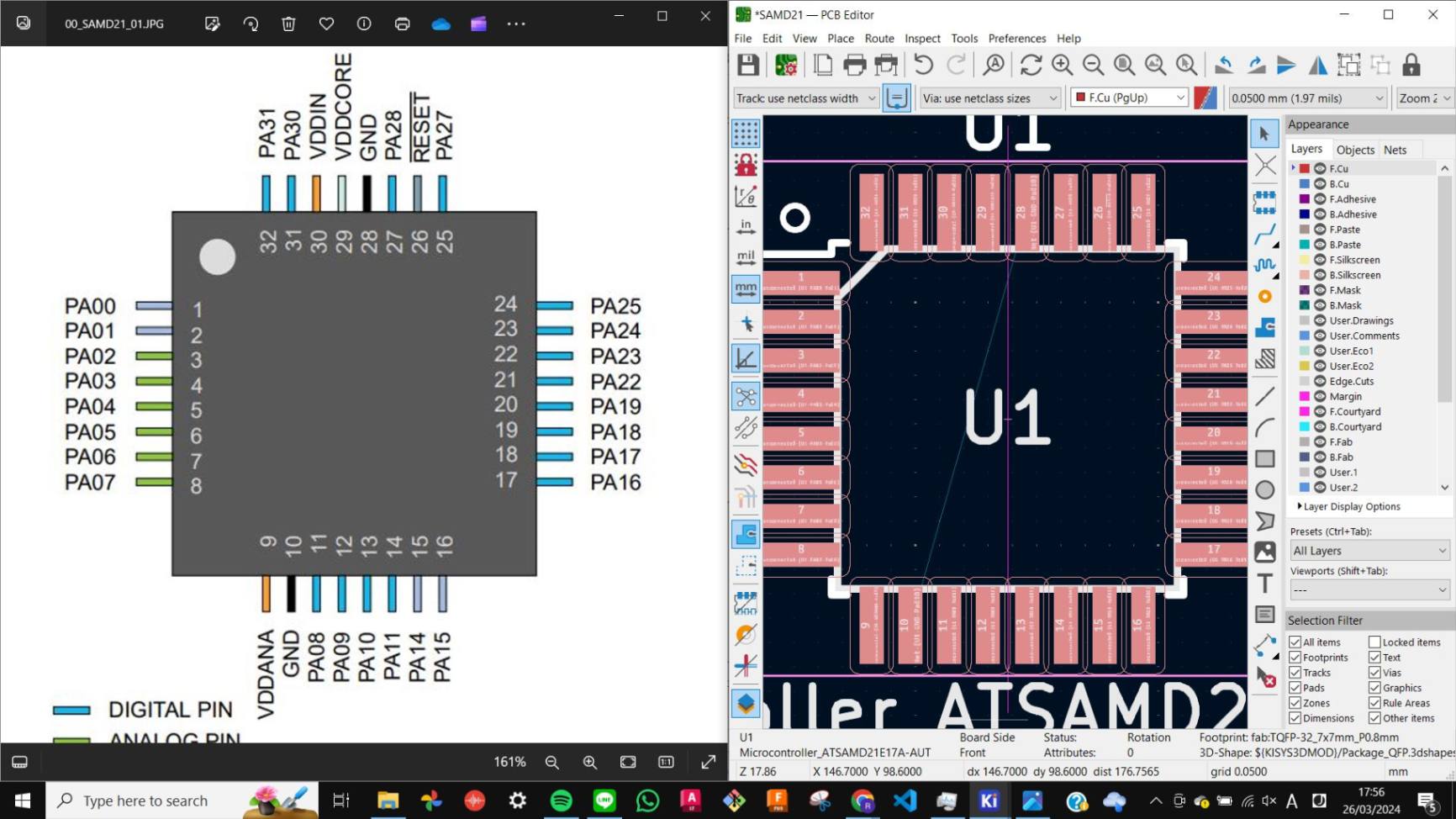
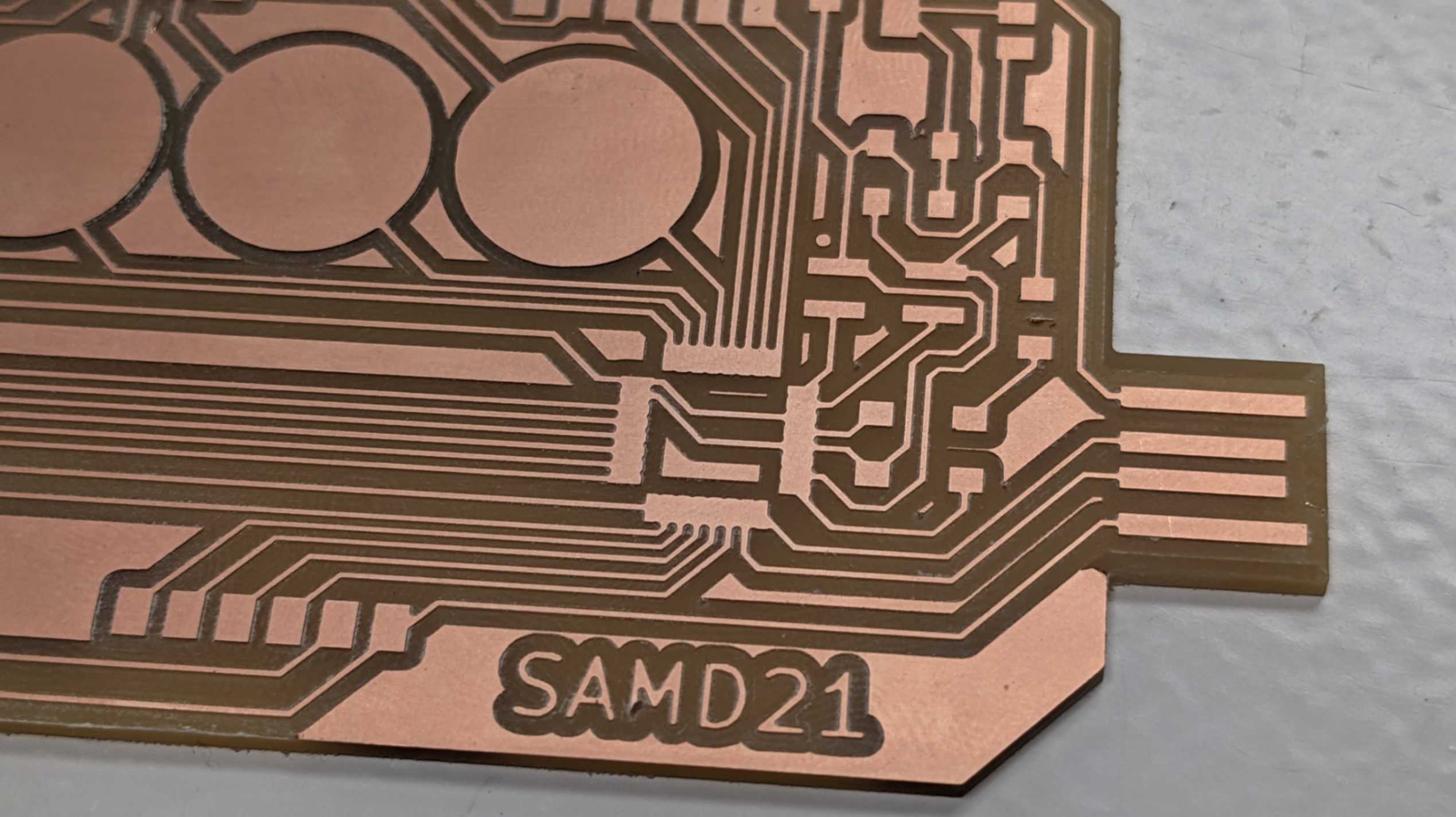
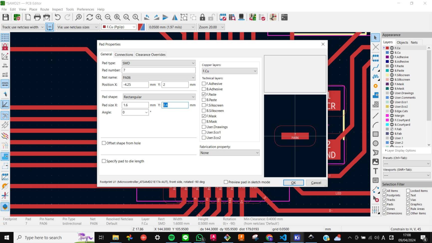
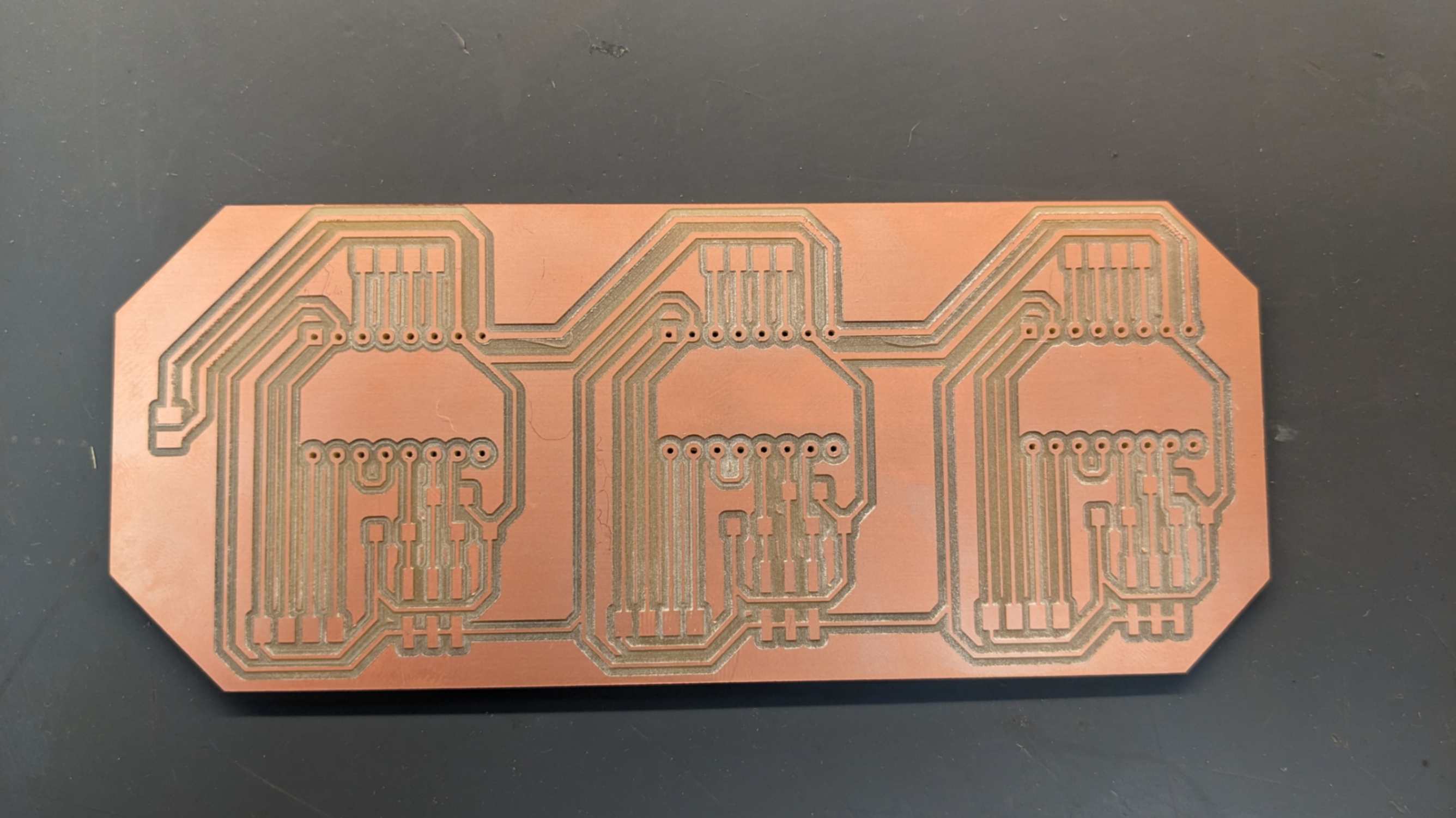
Thinner Footprint on KiCAD
After milling the PCB I found out that the footprint for SAMD21 pins are too close to each other and they were merged. To fix this problem I needed to go back to KiCAD and fix the thickness only for those footprints. I followed the steps below.
- Shift+LeftClick - select a pin
- E - to edit
- Change Pad size Y to 0.4mm
- RightClick - Copy Pad Properties to Default
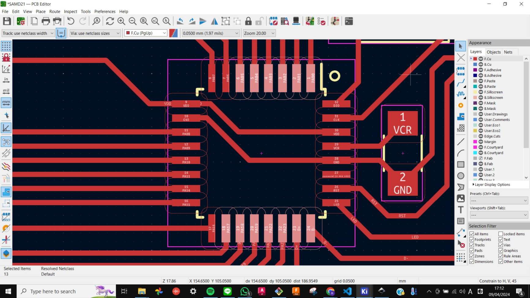
- Select pins that are the same orientation
- RightClick - Paste Default Pad Properties to Selected
- Repeat the process for those in another orientation
Files
outline2.png
trace2.png
outline2.png.rml
trace2.png.rml
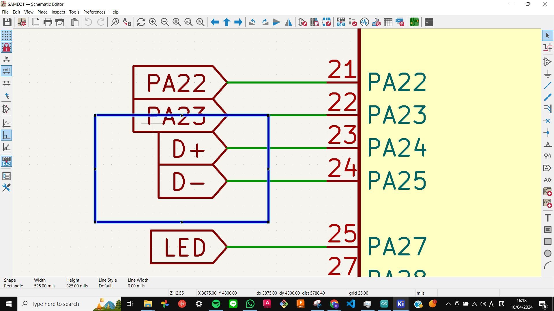
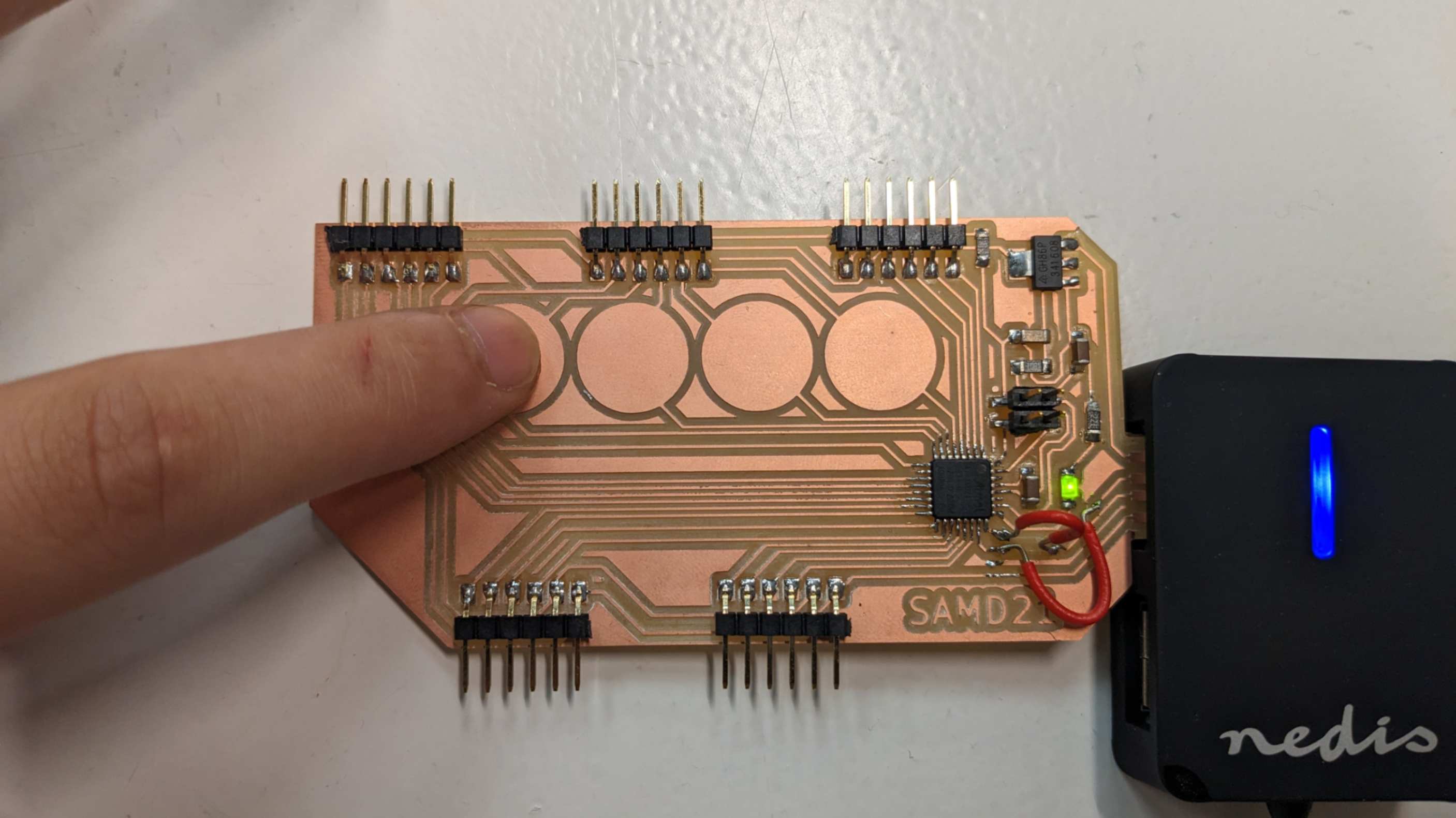
D+ D-
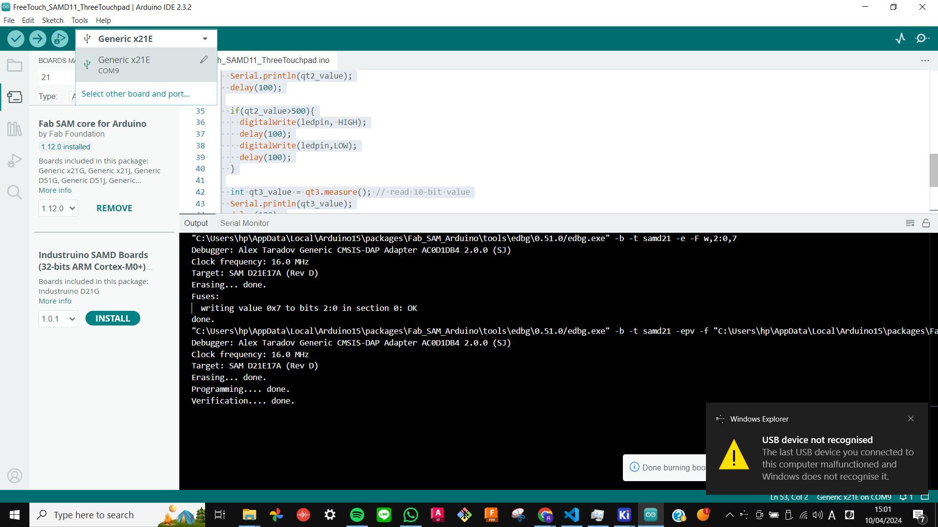
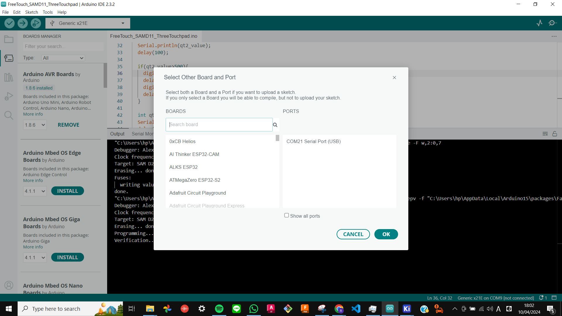
After milling the PCB and soldering components on it, I flashed SAMD21 with the same workflow I did in
Week 8 Embedded Programming
However, after burning the bootloader, my PCB was not recognized as USB. So I did basic troubleshooting such as checking connecting on PCB, connecting different USB ports, and checking my PC setup. Later my tutor found out that I had pins for D+ and D- flipped. I should have checked the table of I/O Multiplexing and Considerations. On the table, it shows USB/DM (D-) and USB/DP (D+).
To fix this problem, my tutor recommended I simply swap connecting by using a wire. This solution fixed the problem and the PCB worked perfectly, however, I made new SMAD21 PCB later because the wire connection is very weak.
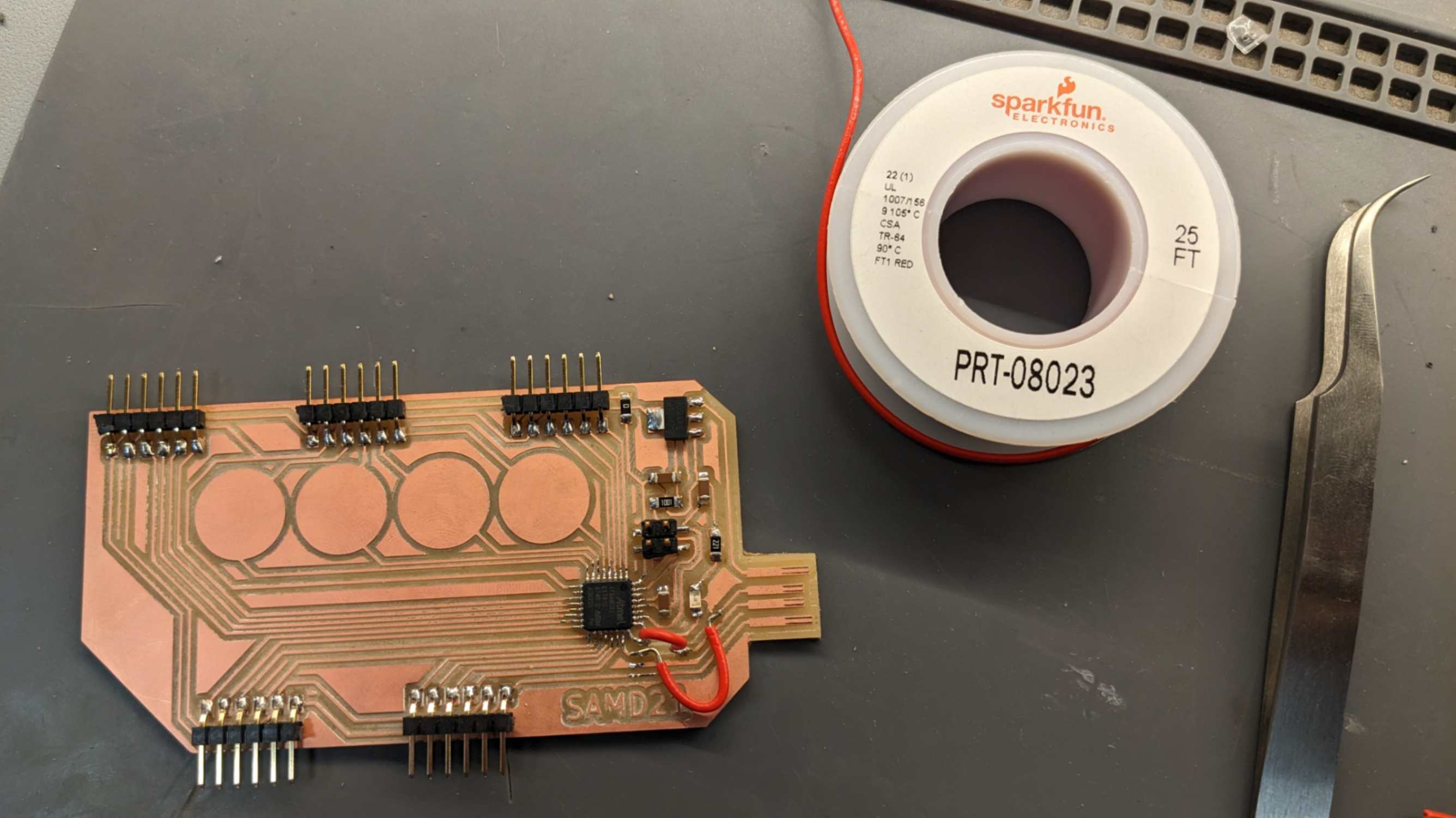
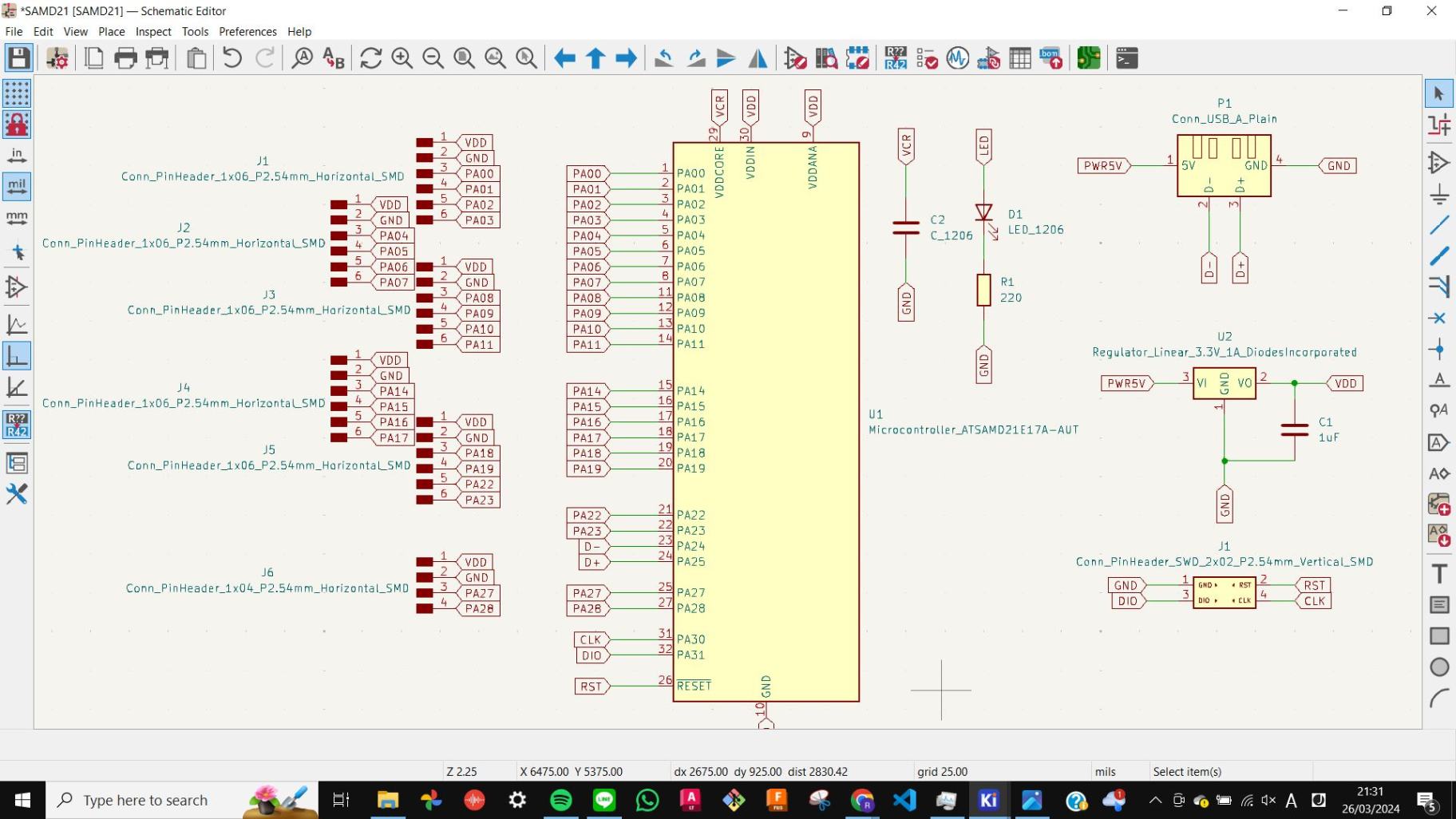
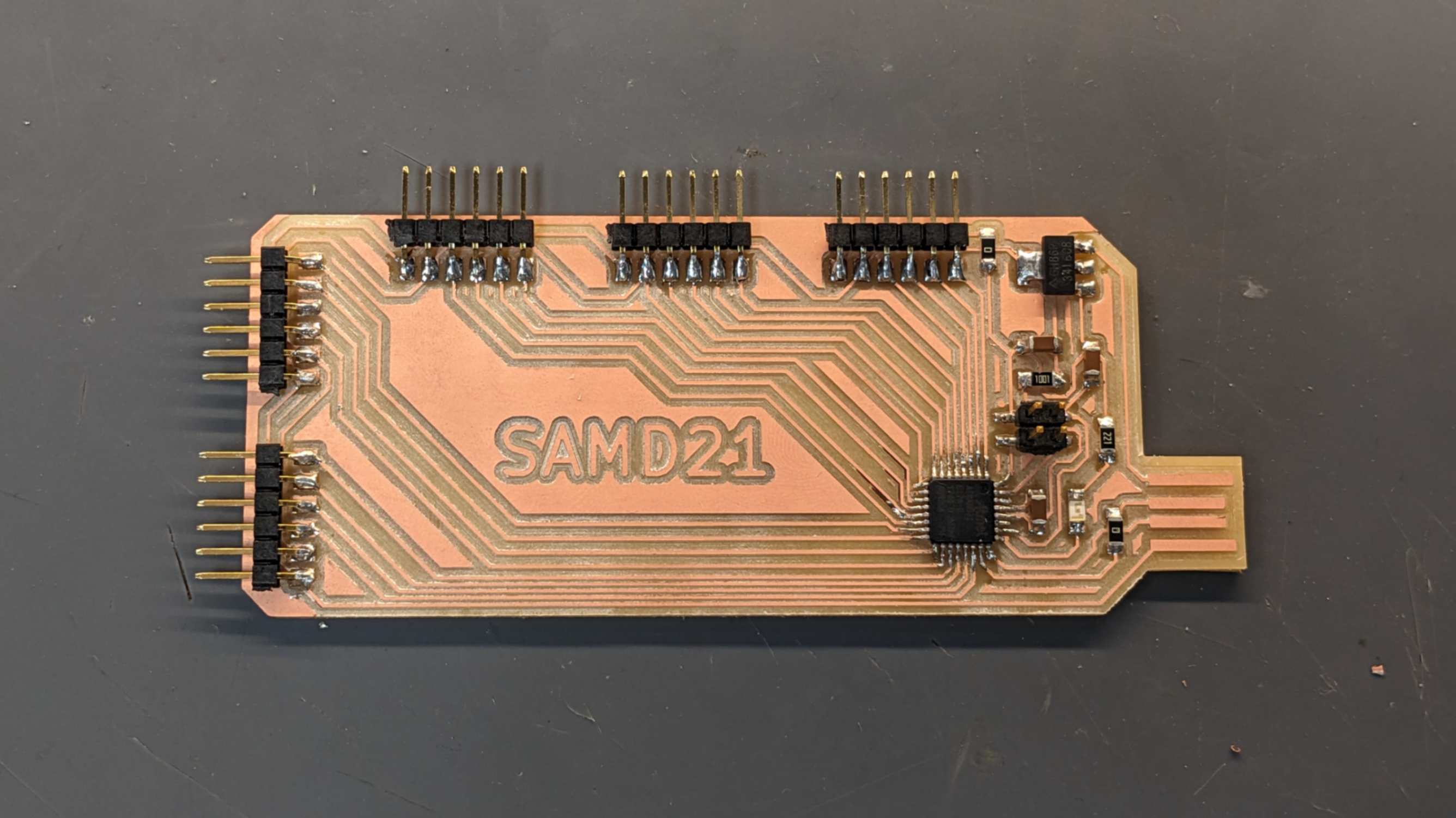
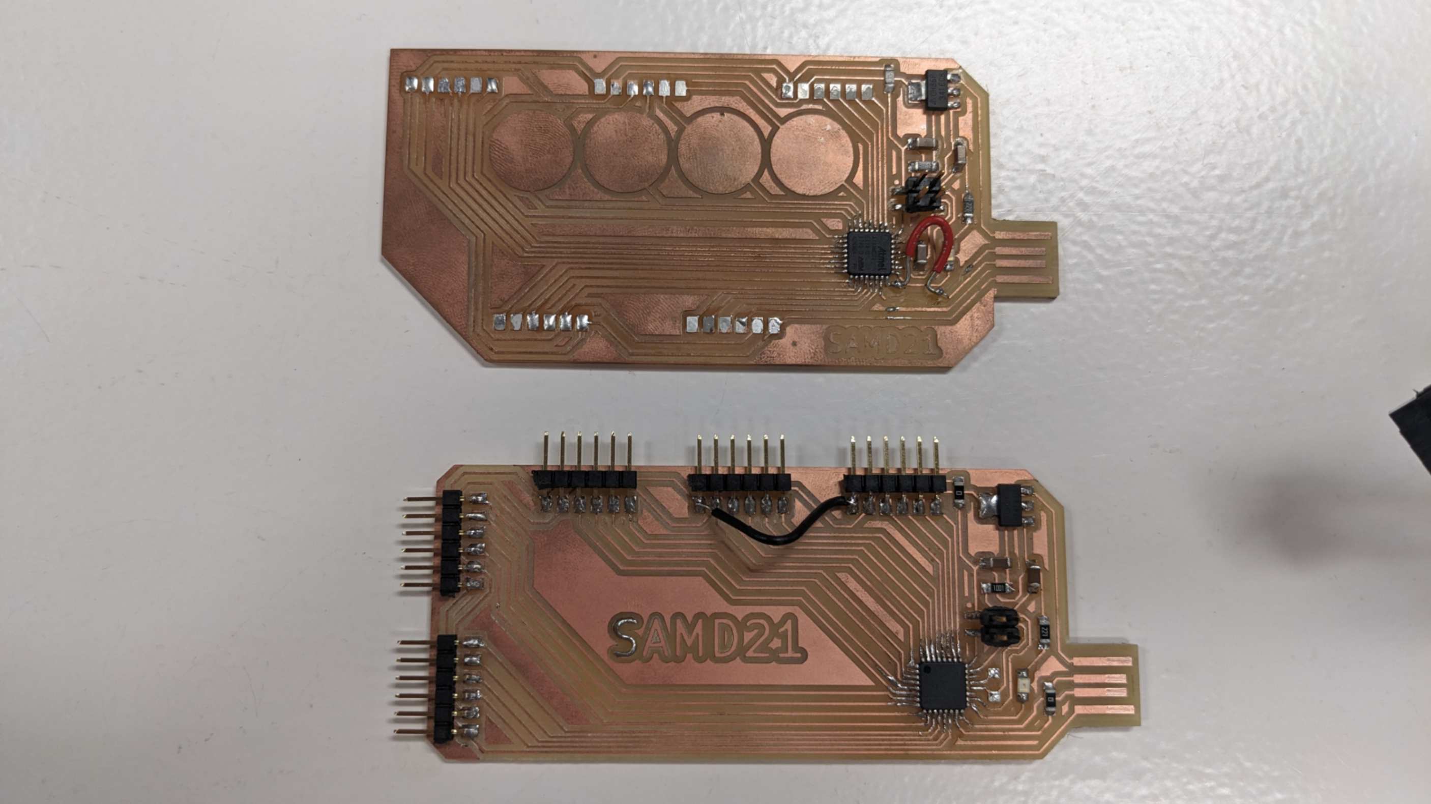
SAMD21 ver 2.0
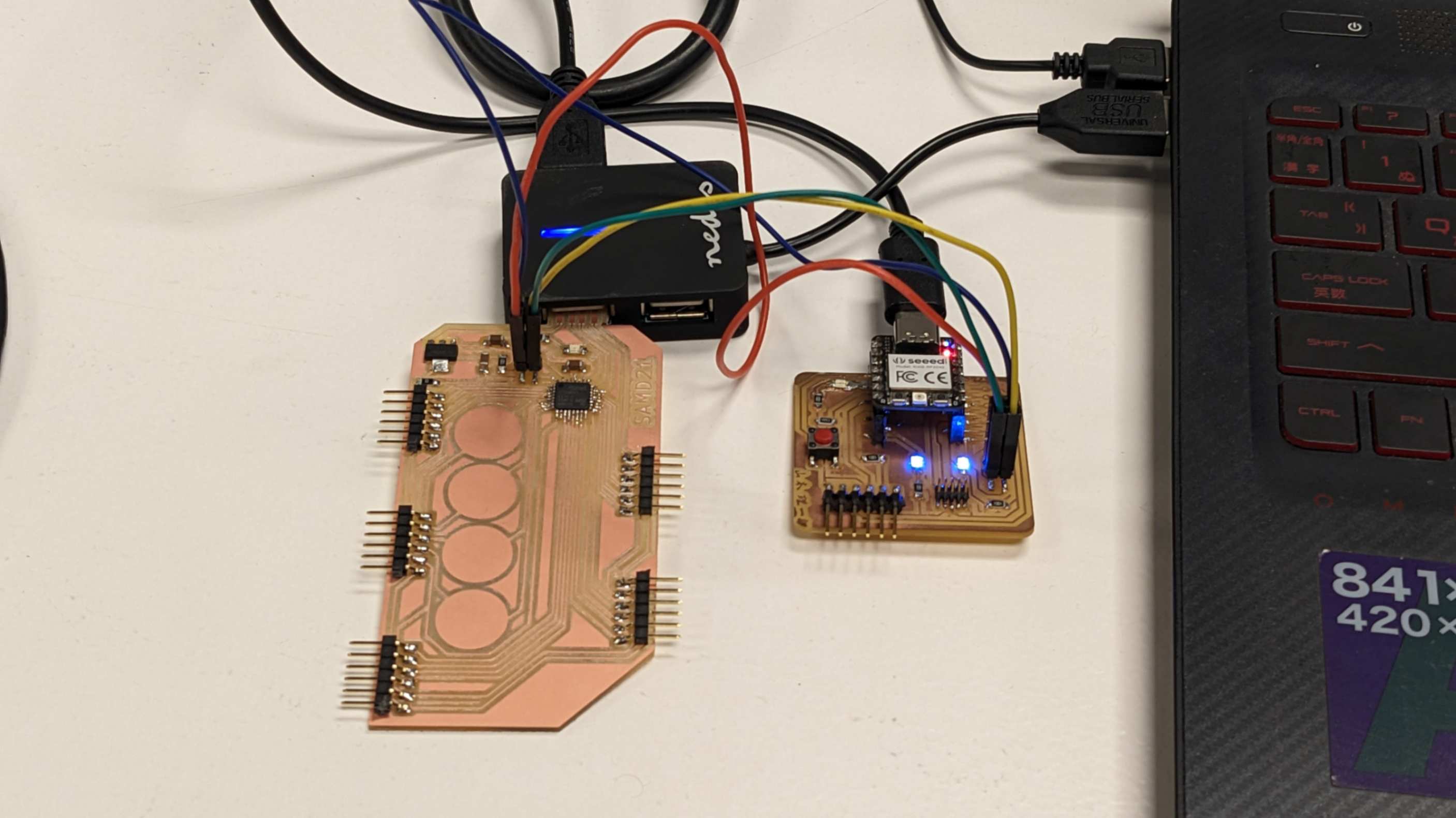
Because the previous SAMD21 PCB had was a frankenstein I wanted to make new one. This time I made it with out capacitive touch because my tutor told me that having capacitive touch in the middle when the pins are connected to device, it might create more noise. This time I use almost all the pins and made the PCB little more compact.
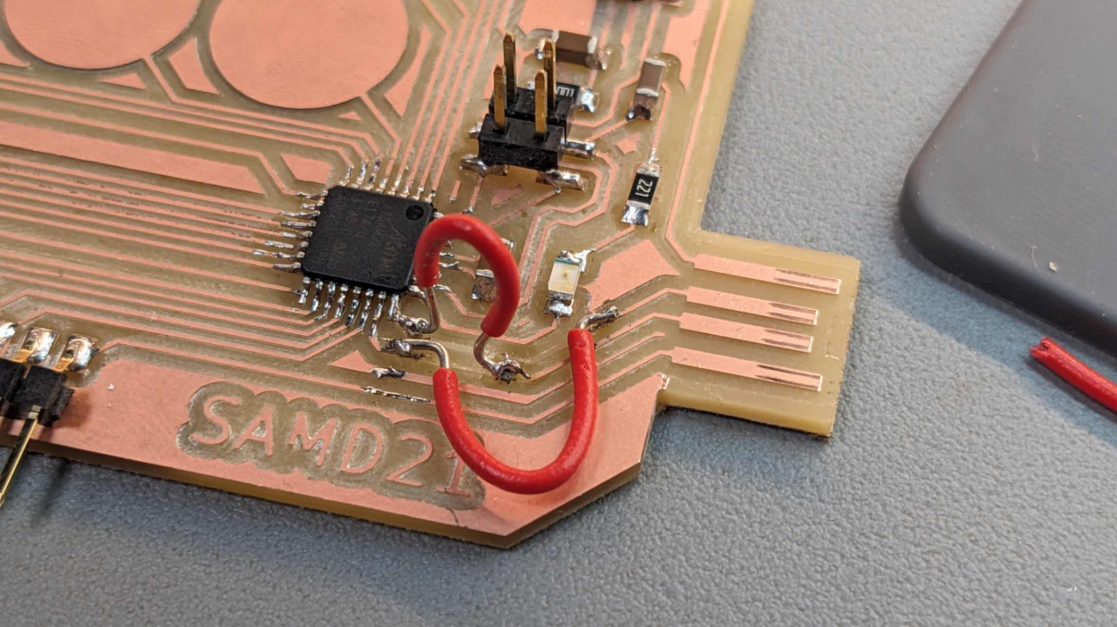
I found a problem when checking the traces it was getting unexpected value for voltage. Later my tutor found out that I had 2 different GND which are not connected to each other. So I used a extra wire to fix it.
Files
SAMD21_02.kicad_pro
SAMD21_02.kicad_sch
SAMD21_02.kicad_pcb
SAMD21_02-F_Cu.svg
outline02.png
trace02.png
outline02.png.rml
trace02.png.rml
DJ Potentiometer
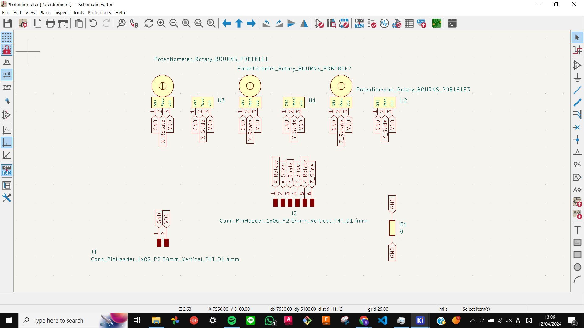
For this week's assignment, I wanted to try using potentiometers to control stepper motors like a DJ.
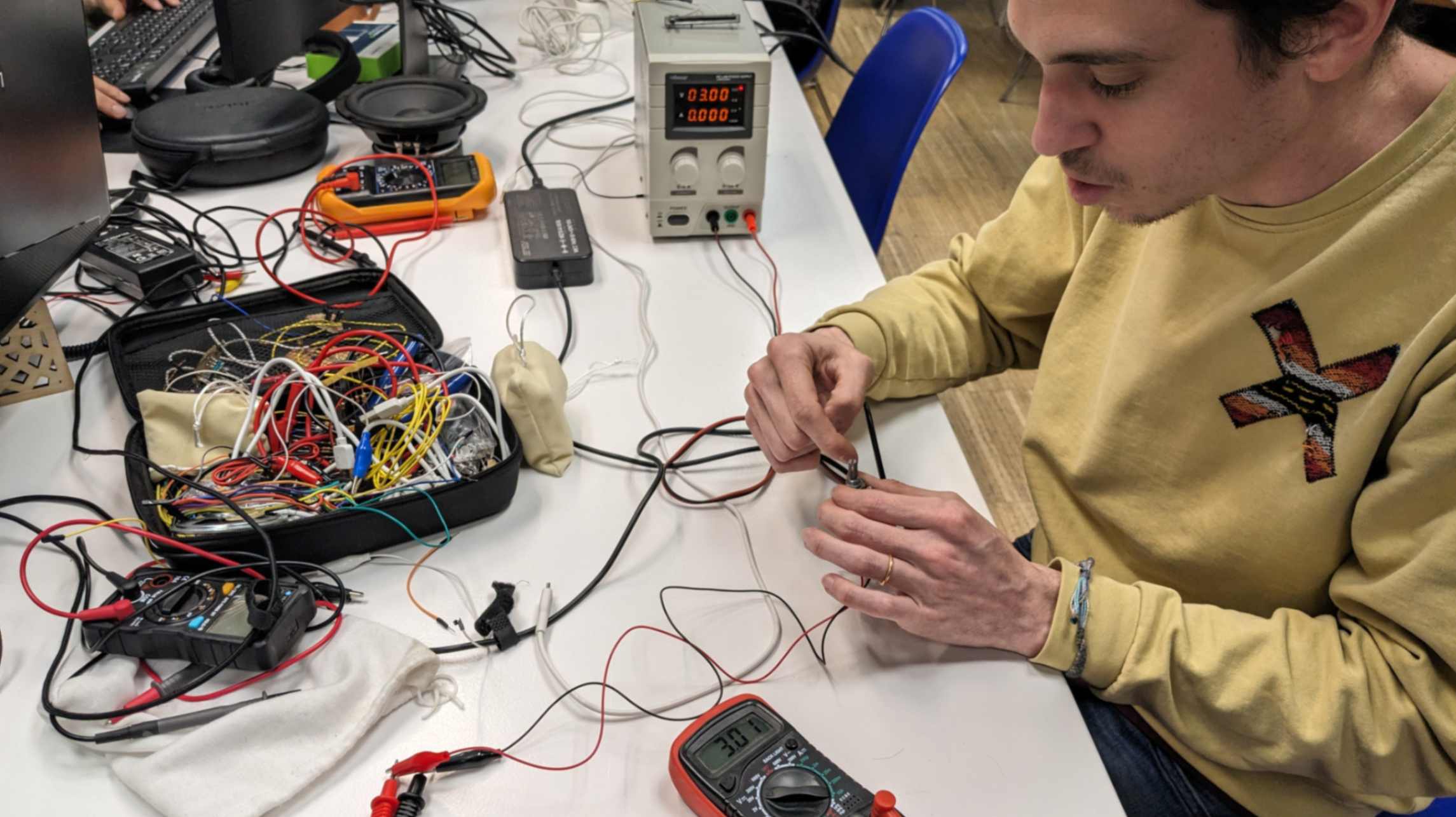
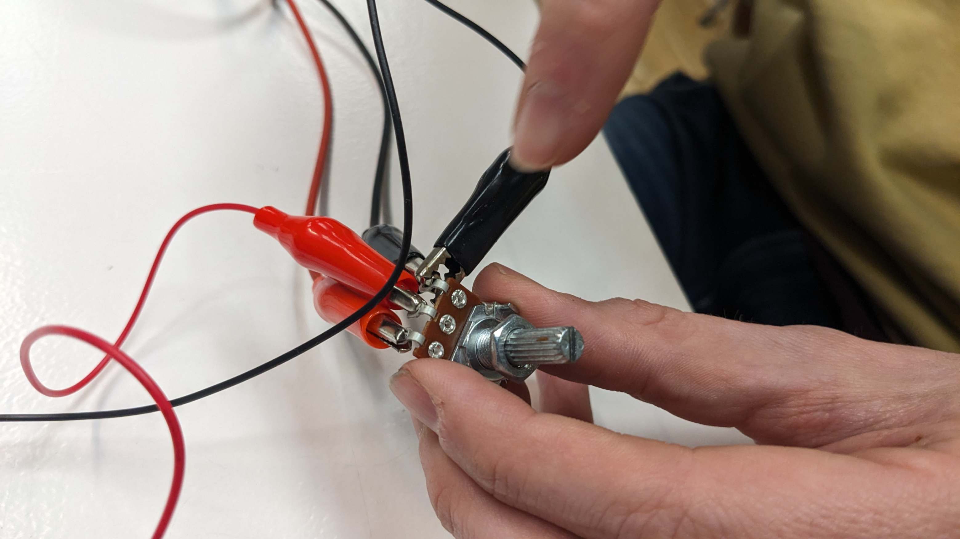
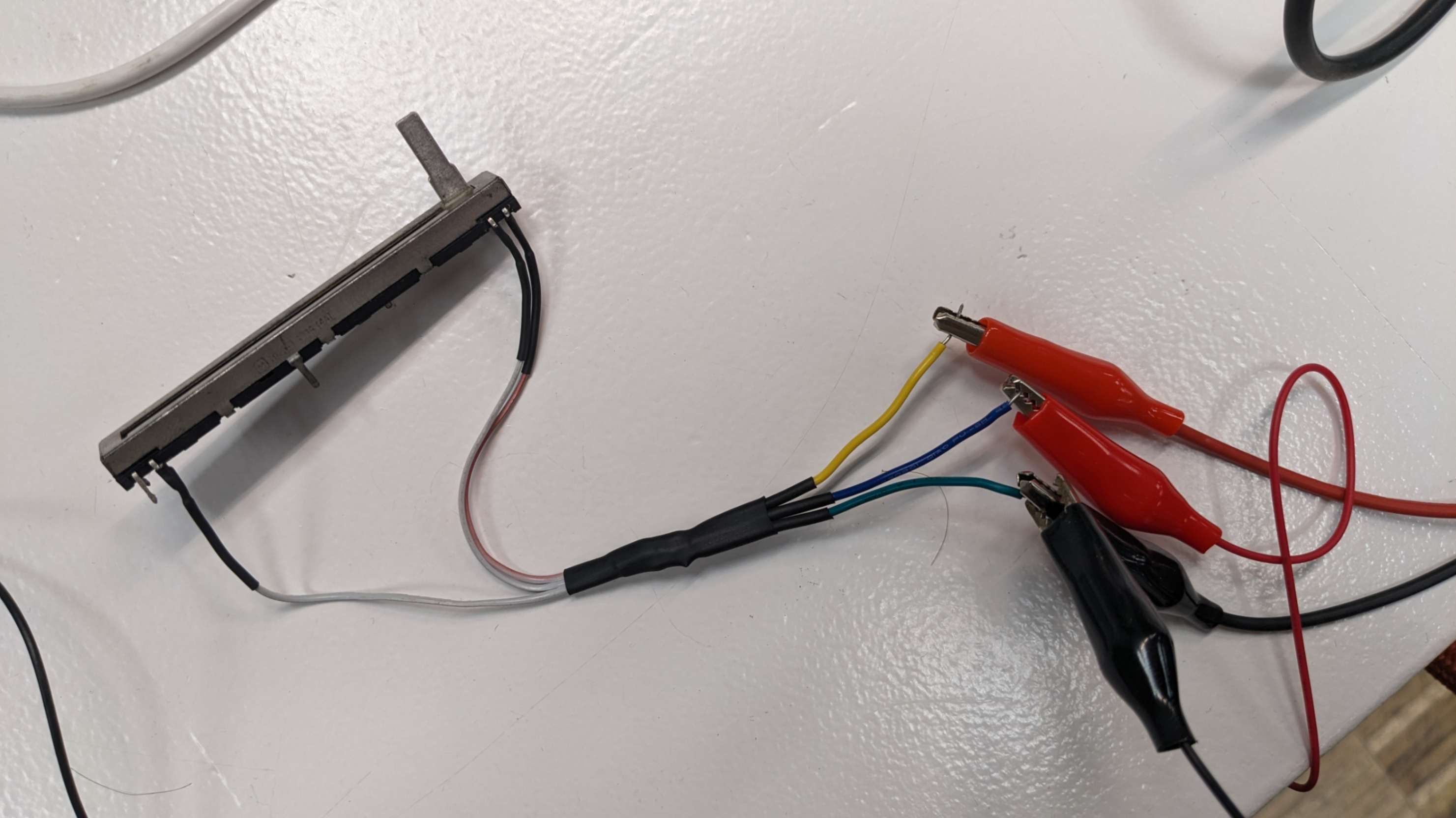
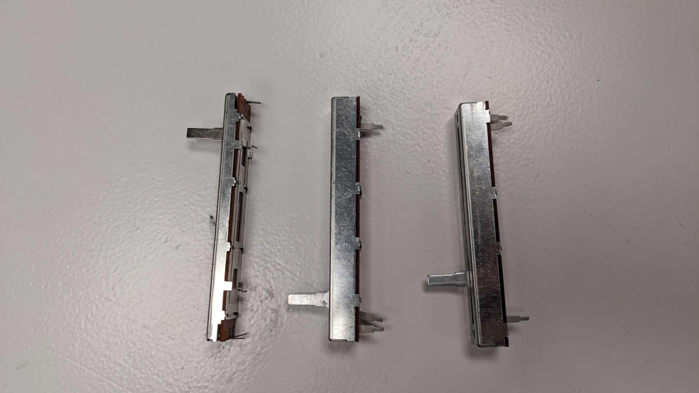
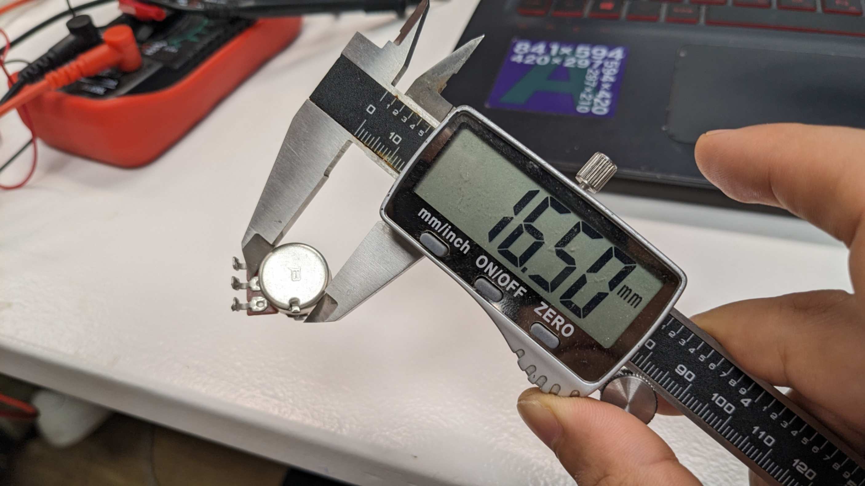
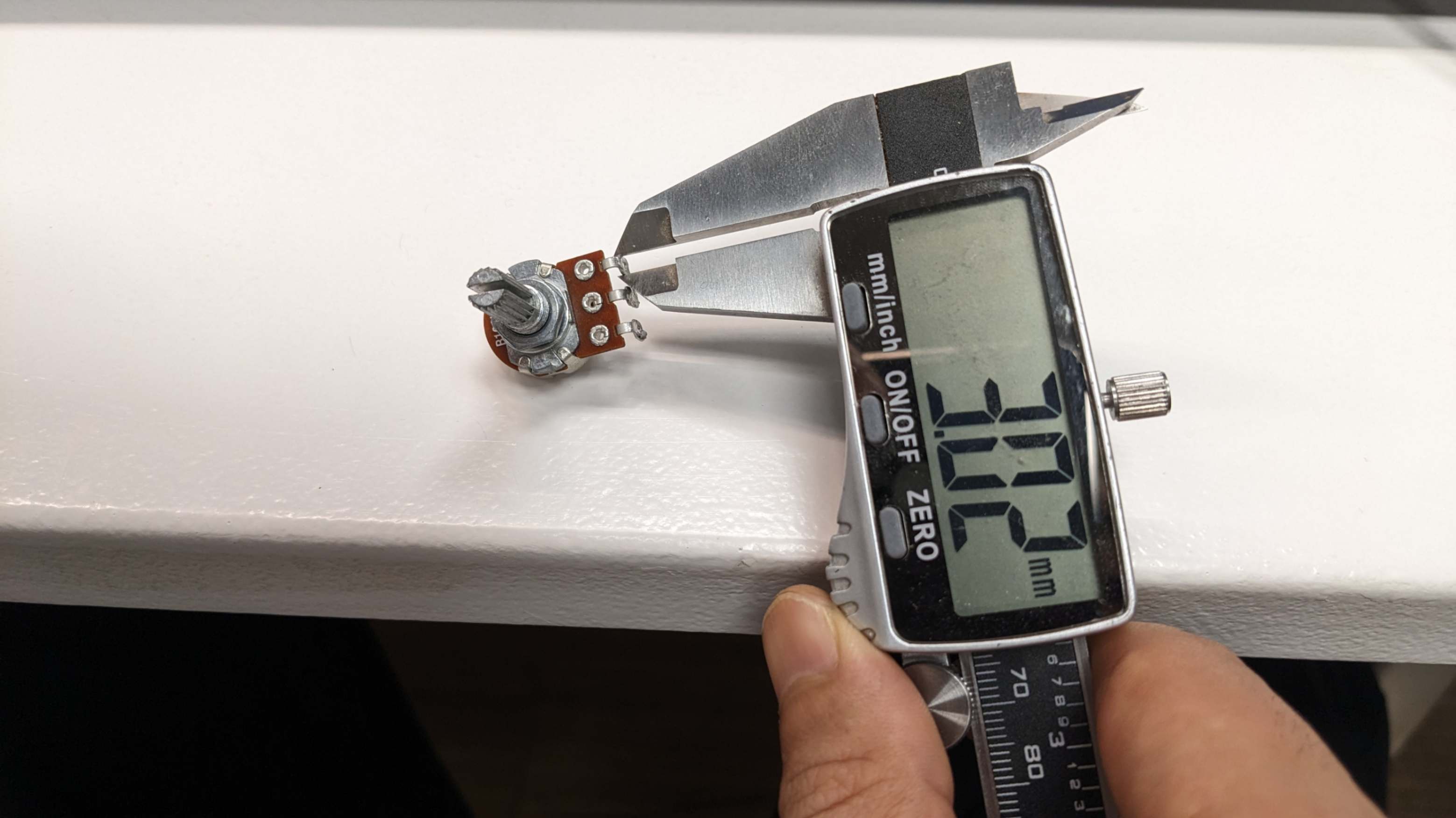
First I checked with my tutor and he showed me potentiometers that are available in the lab. After that, I decided that I wanted to play with a rotational potentiometer and a sliding potentiometer. So I grabbed them and checked their condition because some of them were dusty and there was a chance that they might not work properly.
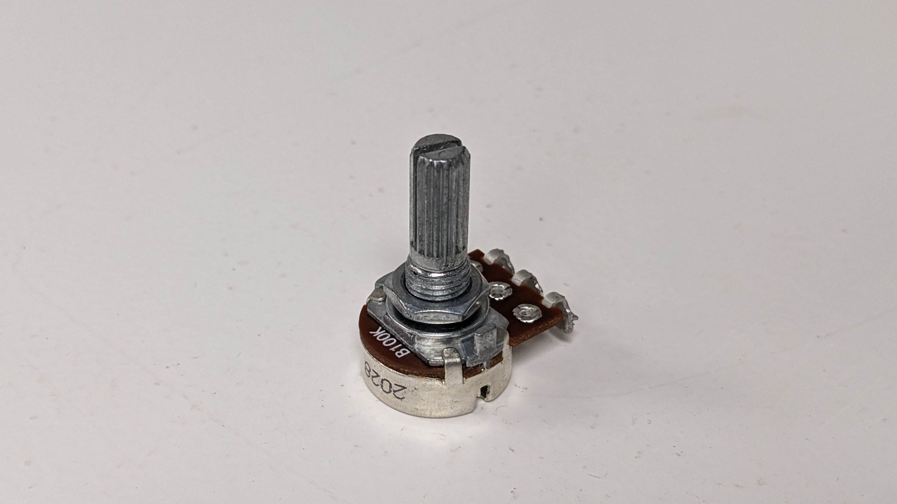
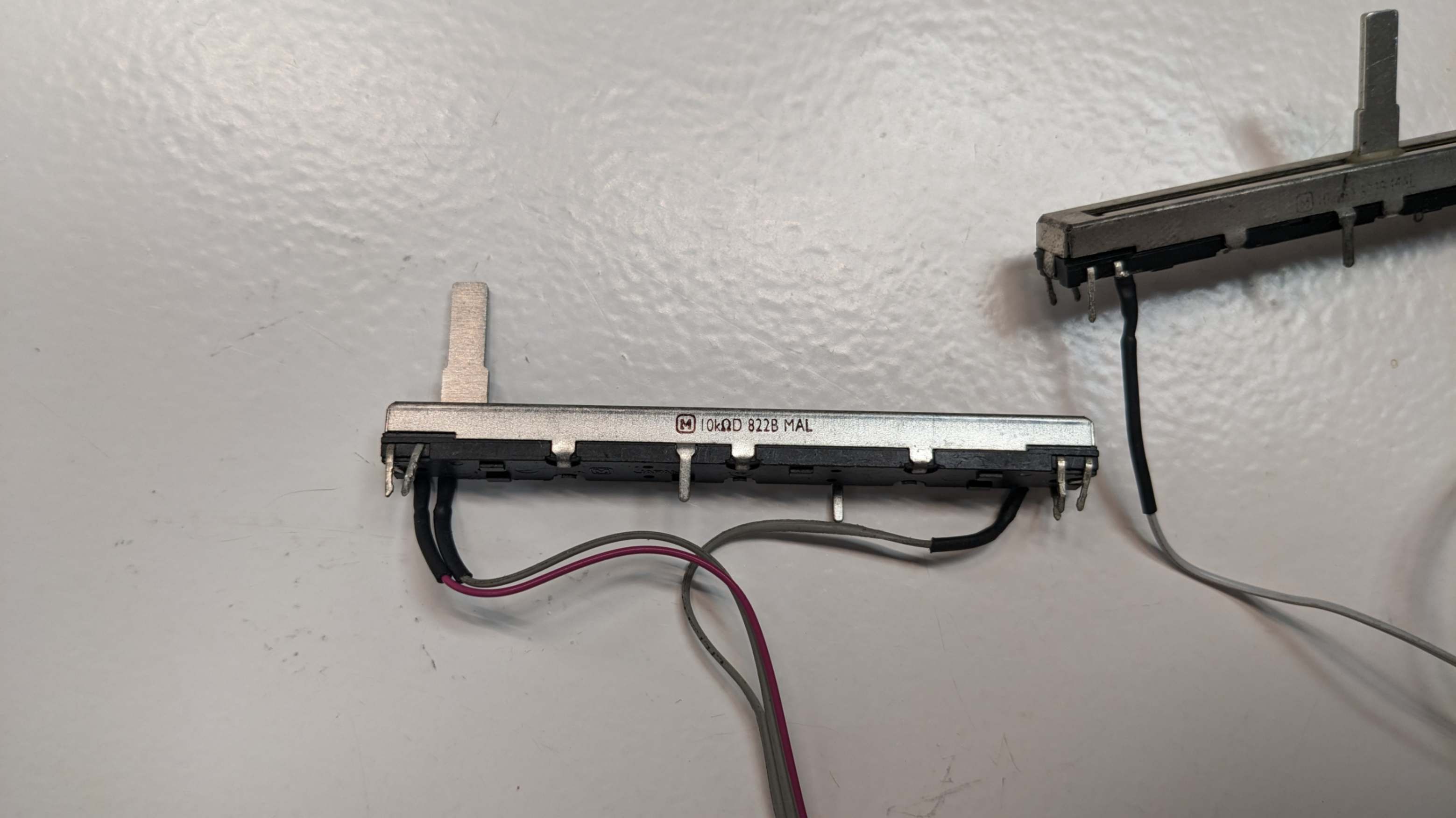
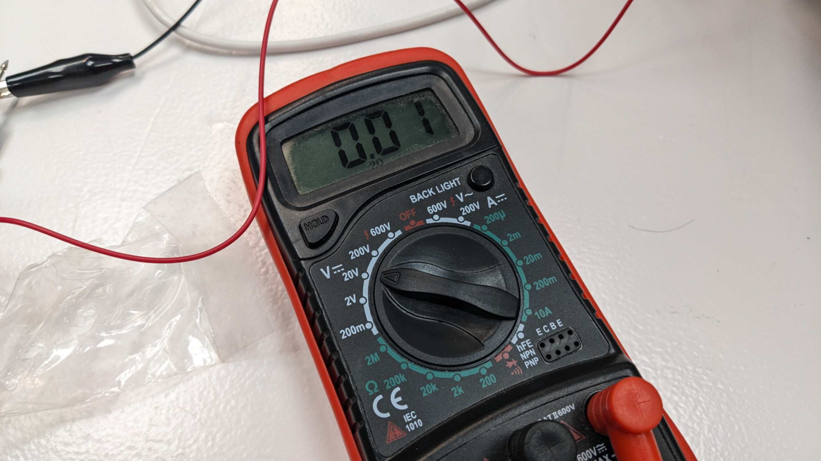
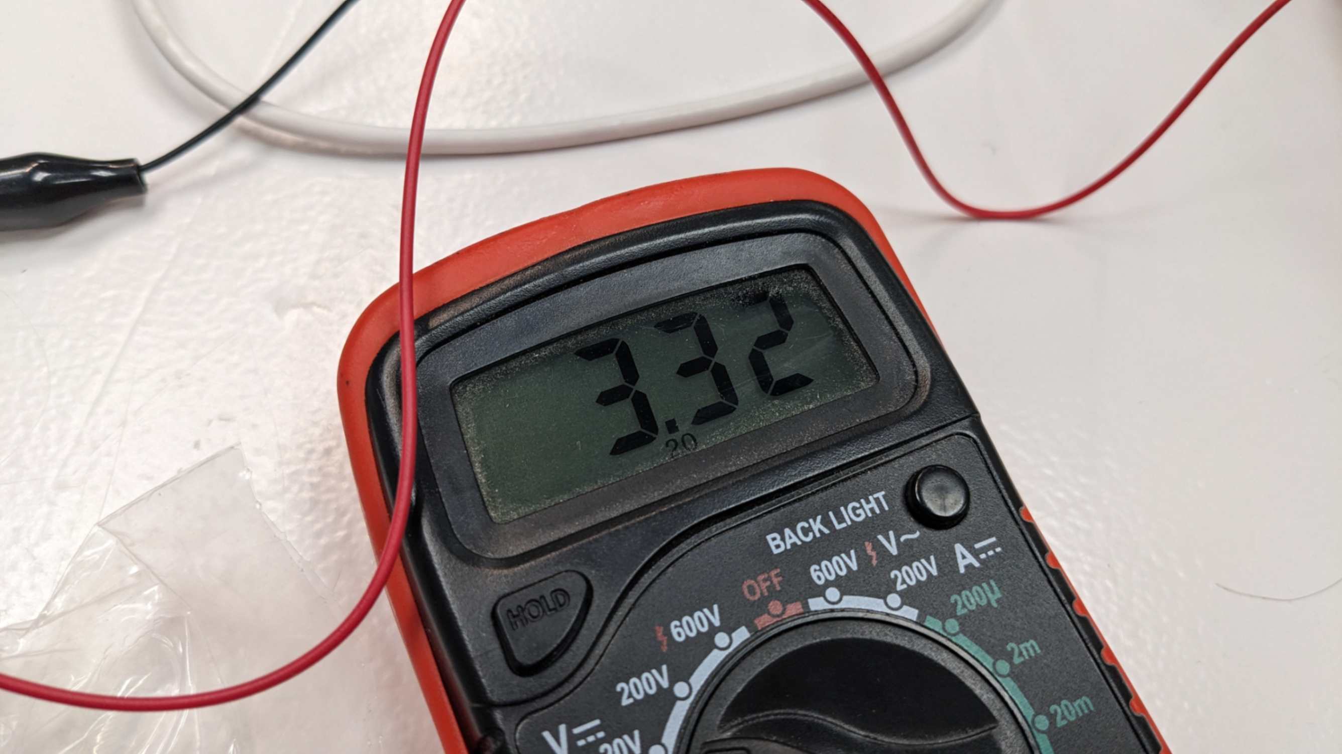
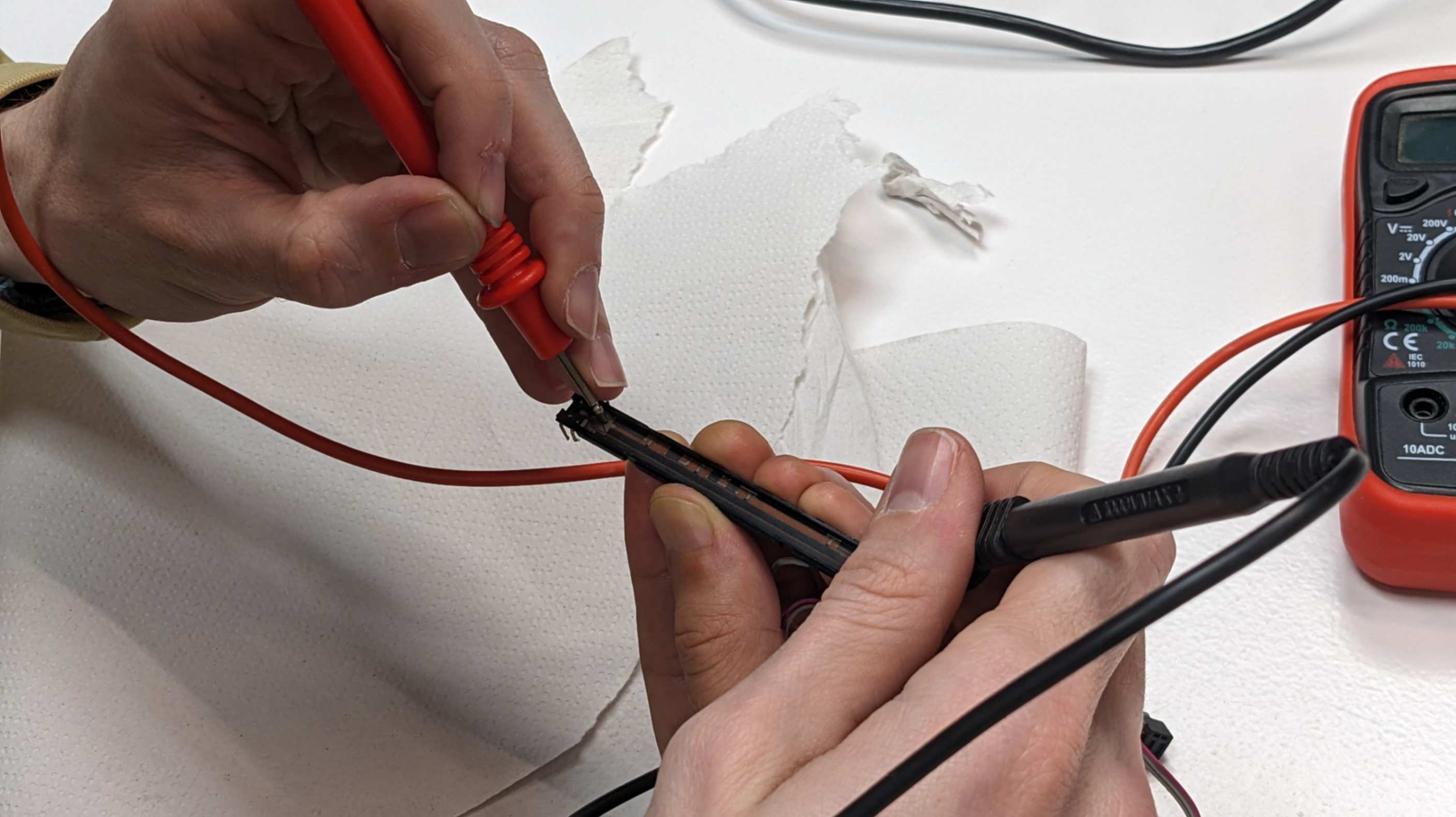
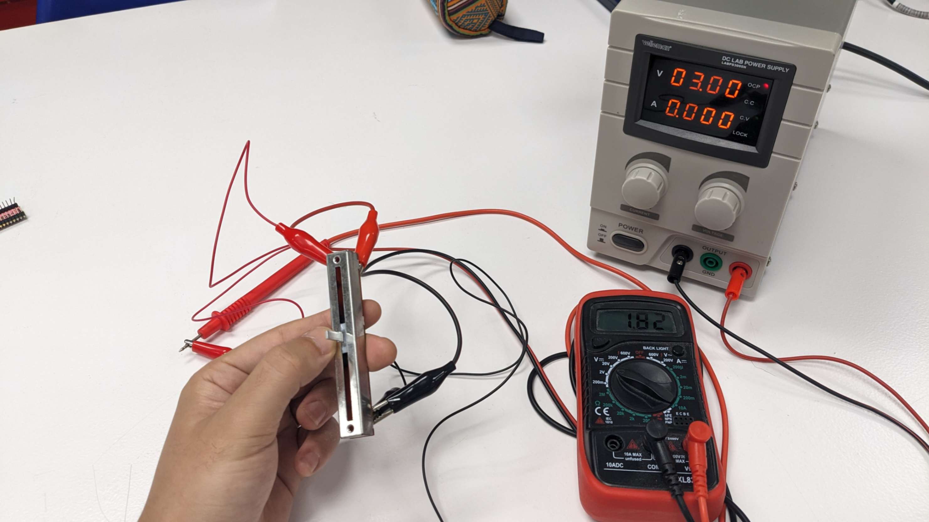
To check the condition, there are usually 3 pins coming out from the potentiometer, connect a power supply to the ones on the sides (usually GND & VDD) 0and connect the middle one (usually for reading voltage) to a multimeter. For the rotational potentiometer, I opened a new package and for the sliding potentiometer all of them in the lab was not working properly so I ended up buying at Charles Servei de Components Electrònics

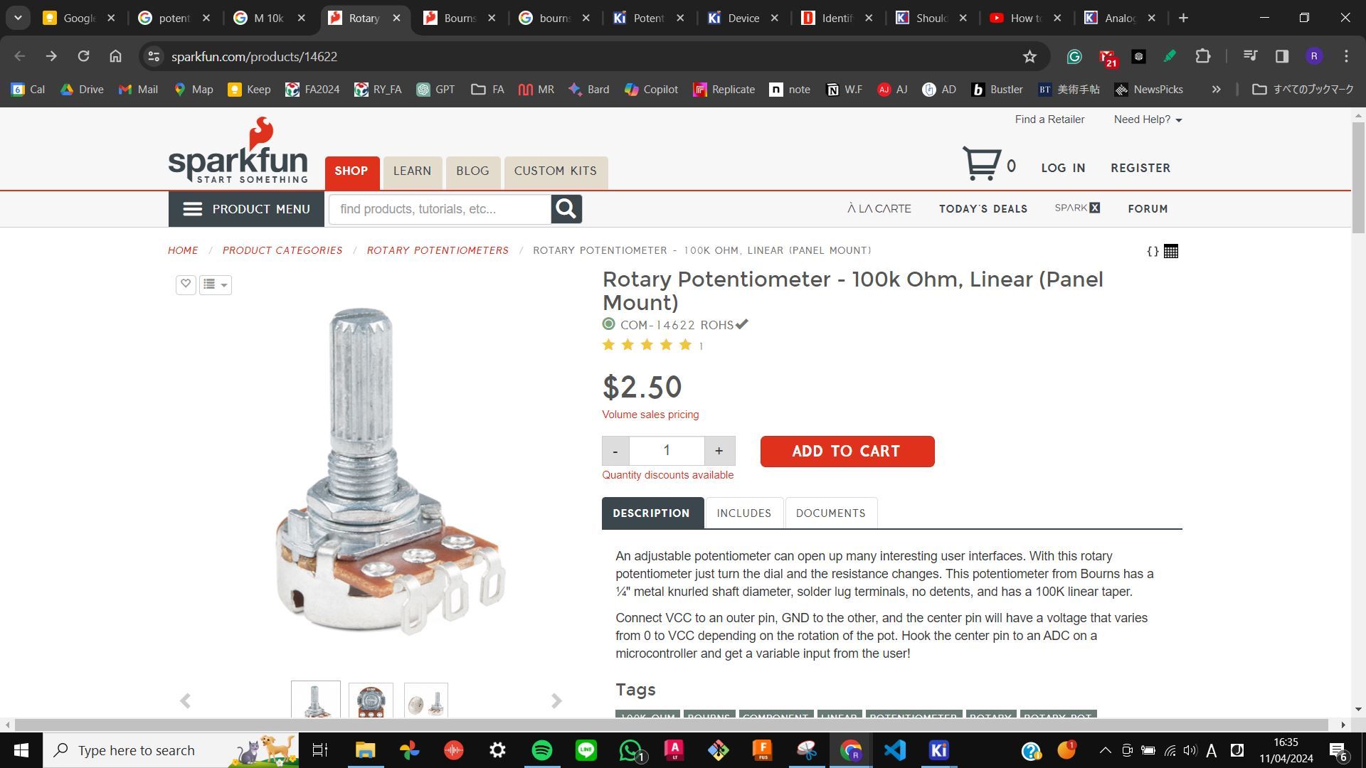
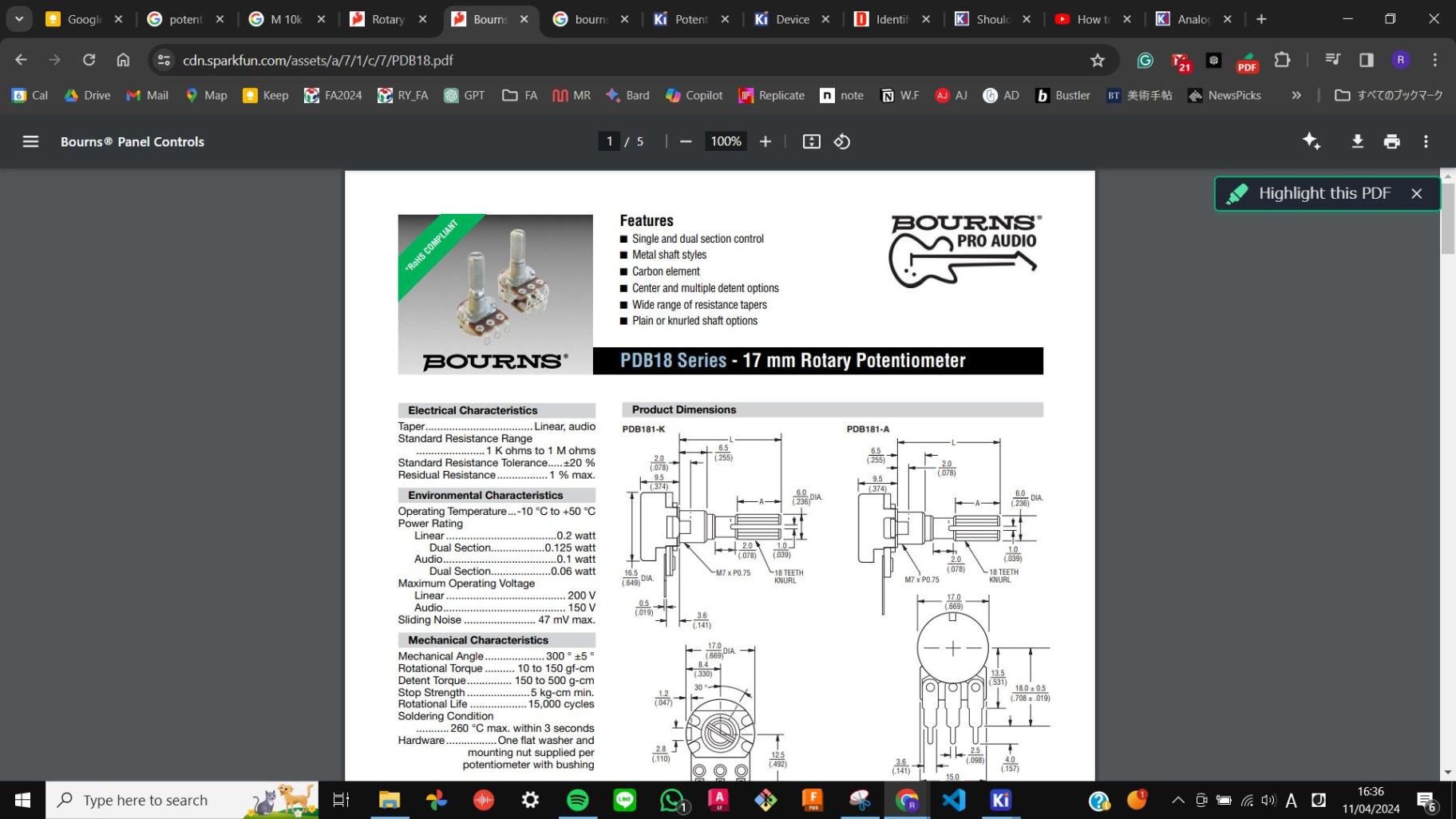
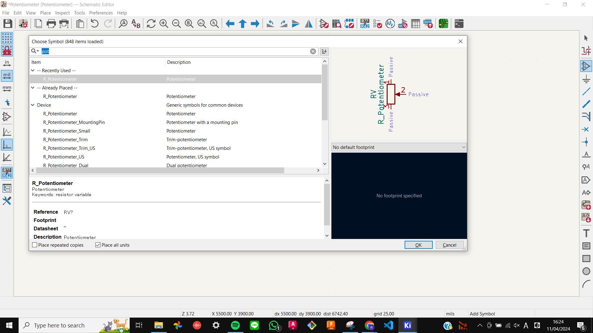
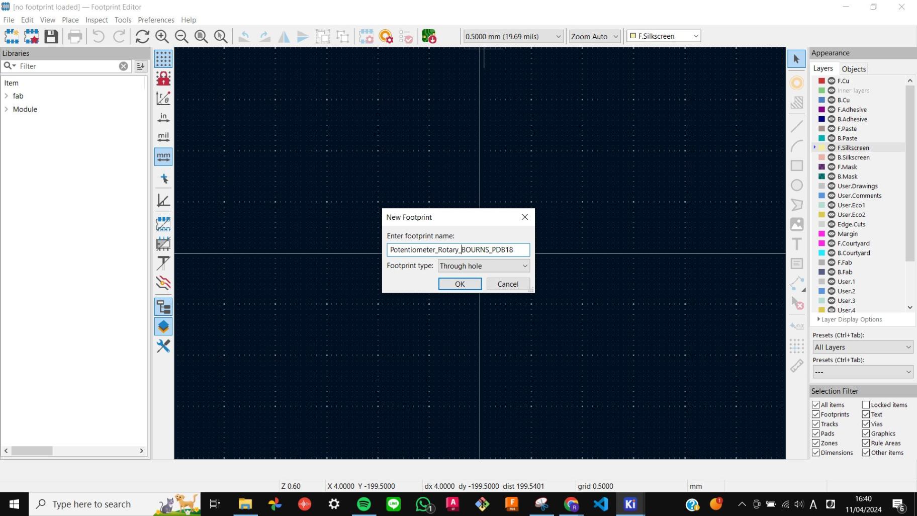
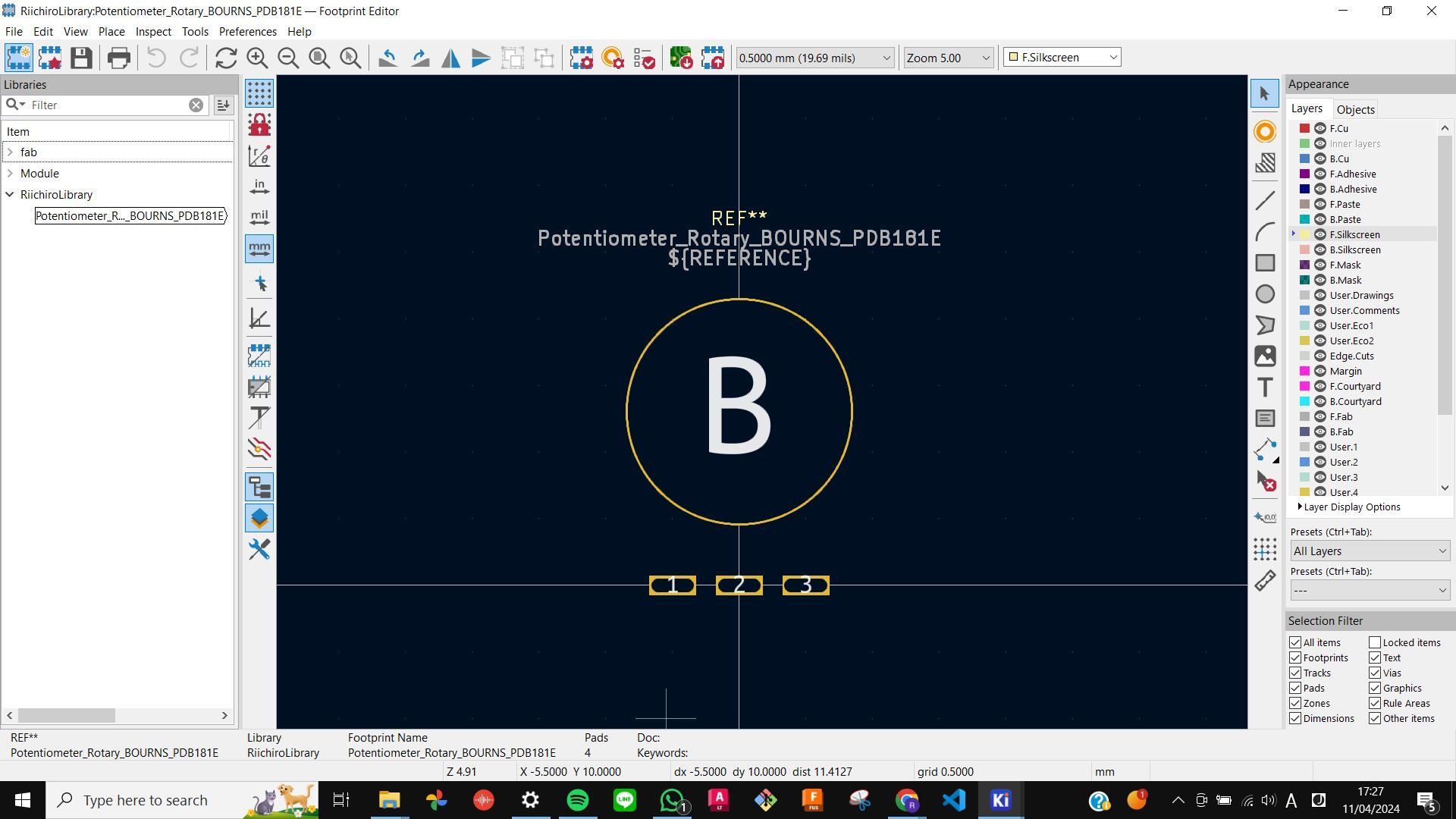
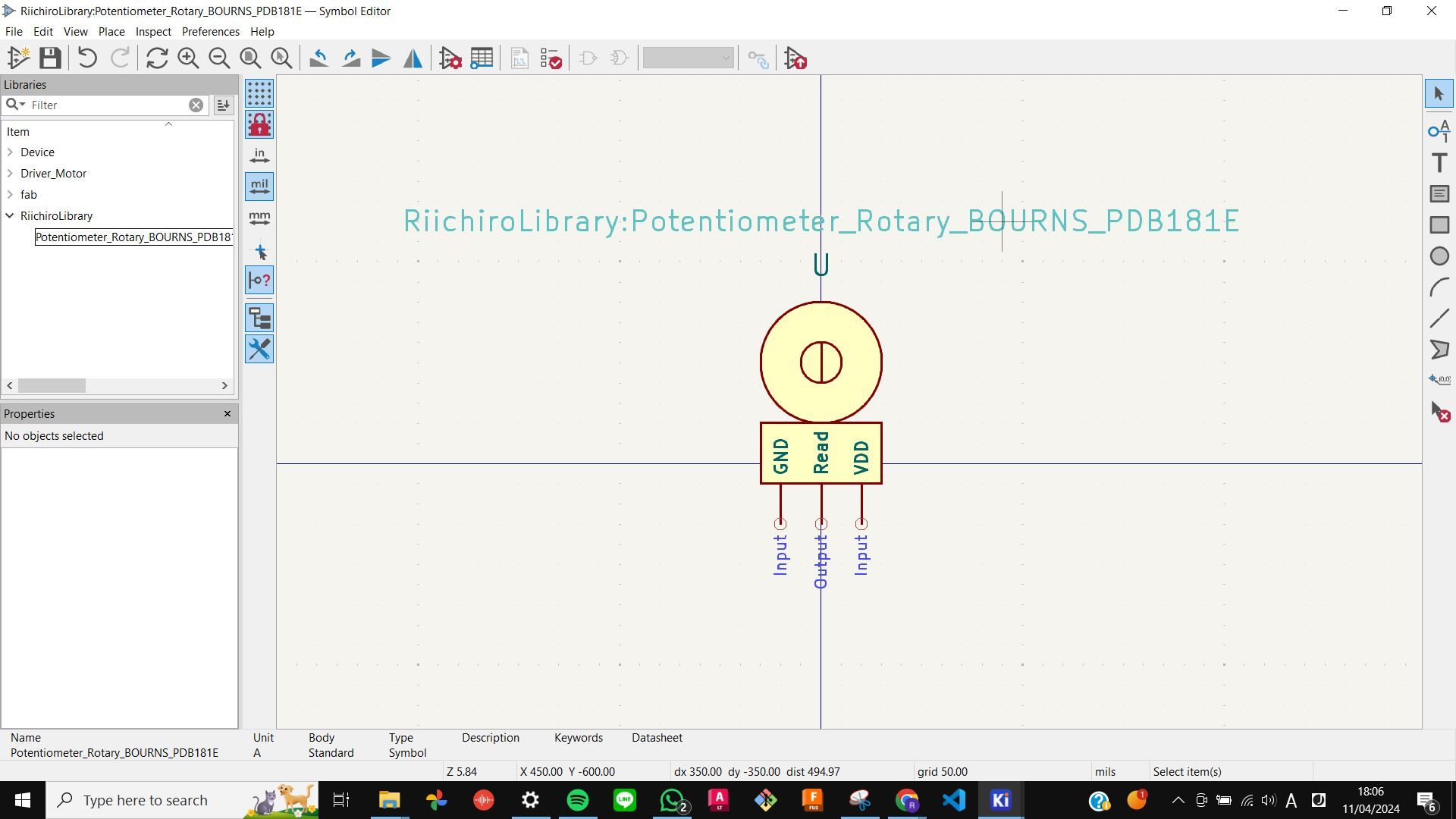
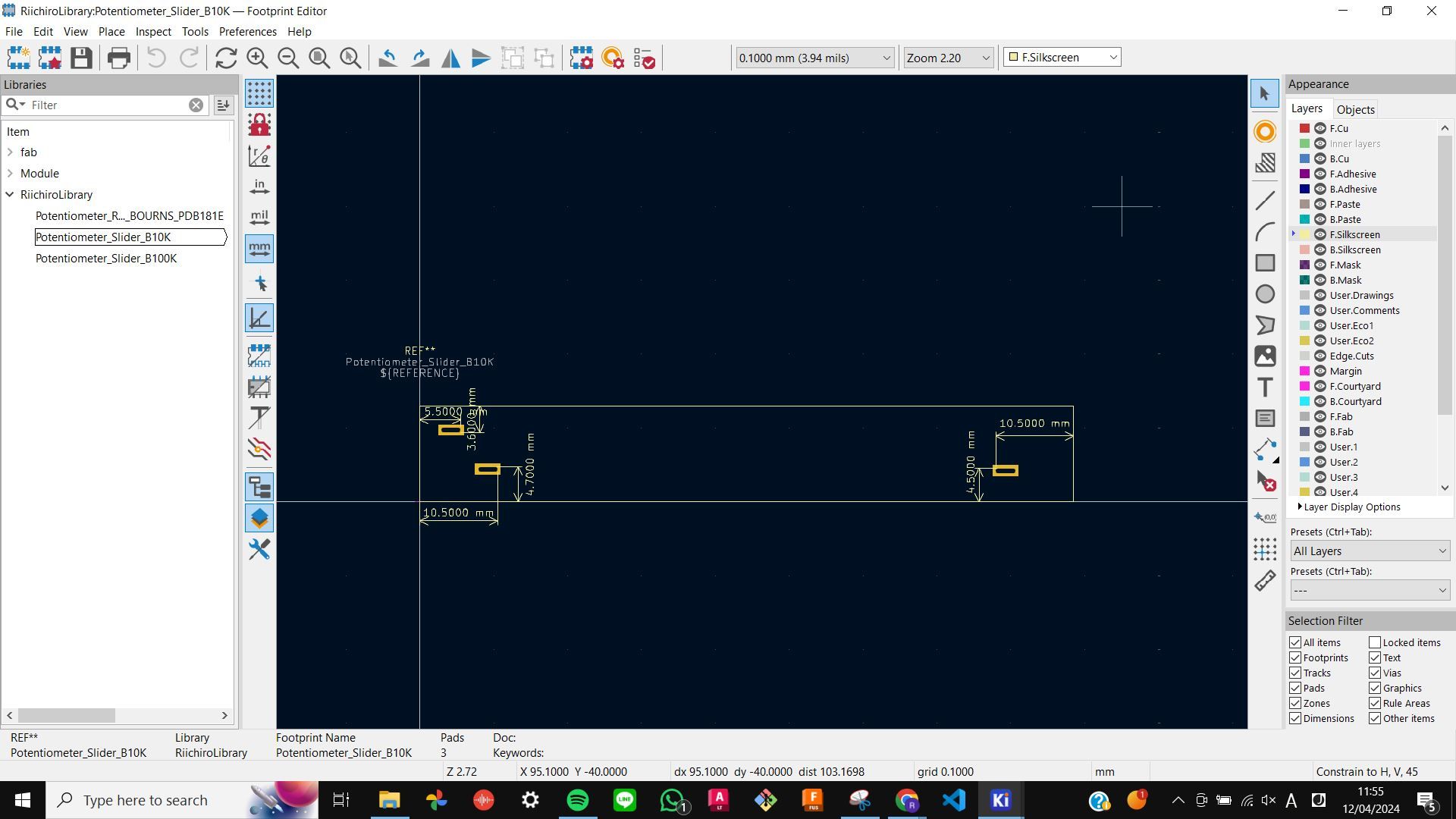
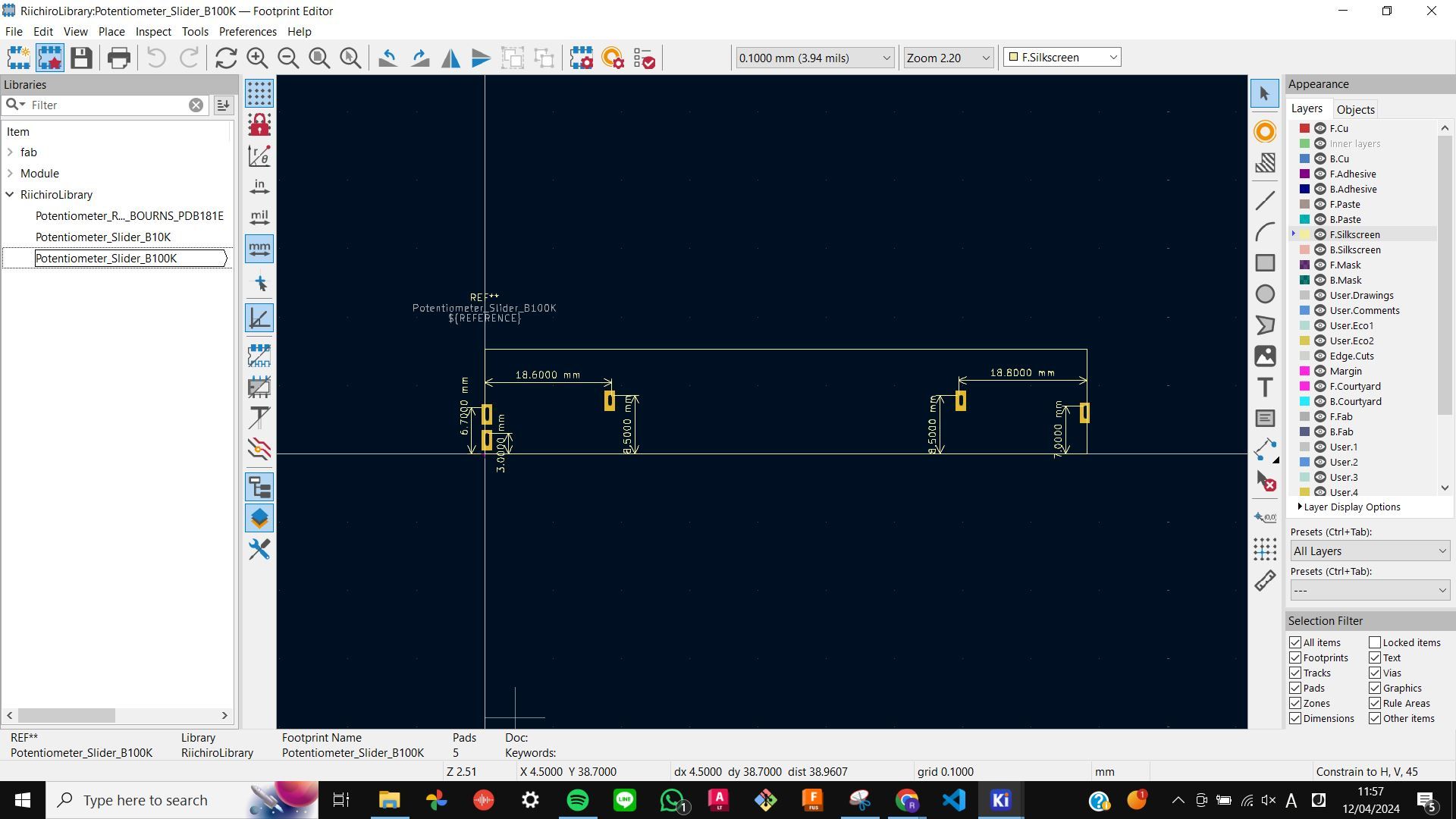
Because I could not find a symbol and footprint library on KiCAD for these analogue potentiometers, my tutor advised me to make them by myself. I measured all the necessary dimensions and followed this YouTube video
How to design custom Footprints & Symbols in Kicad
The workflow is not too hard and I am actually glad to know how to do this.
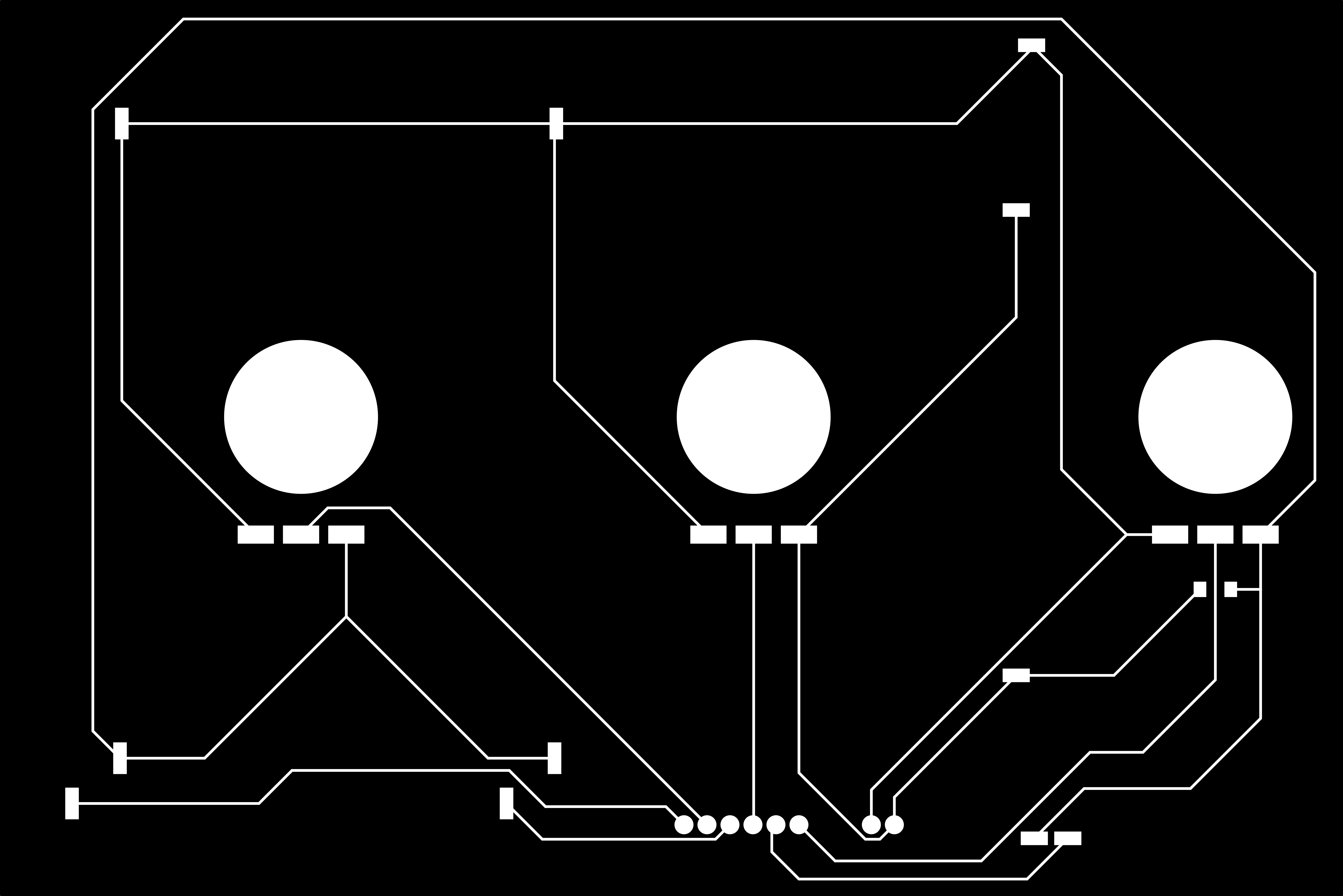
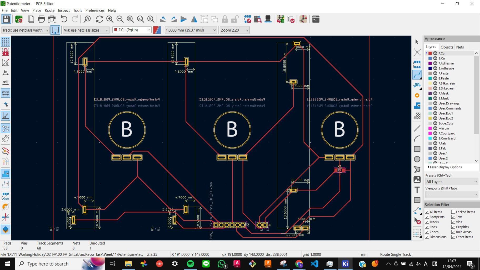
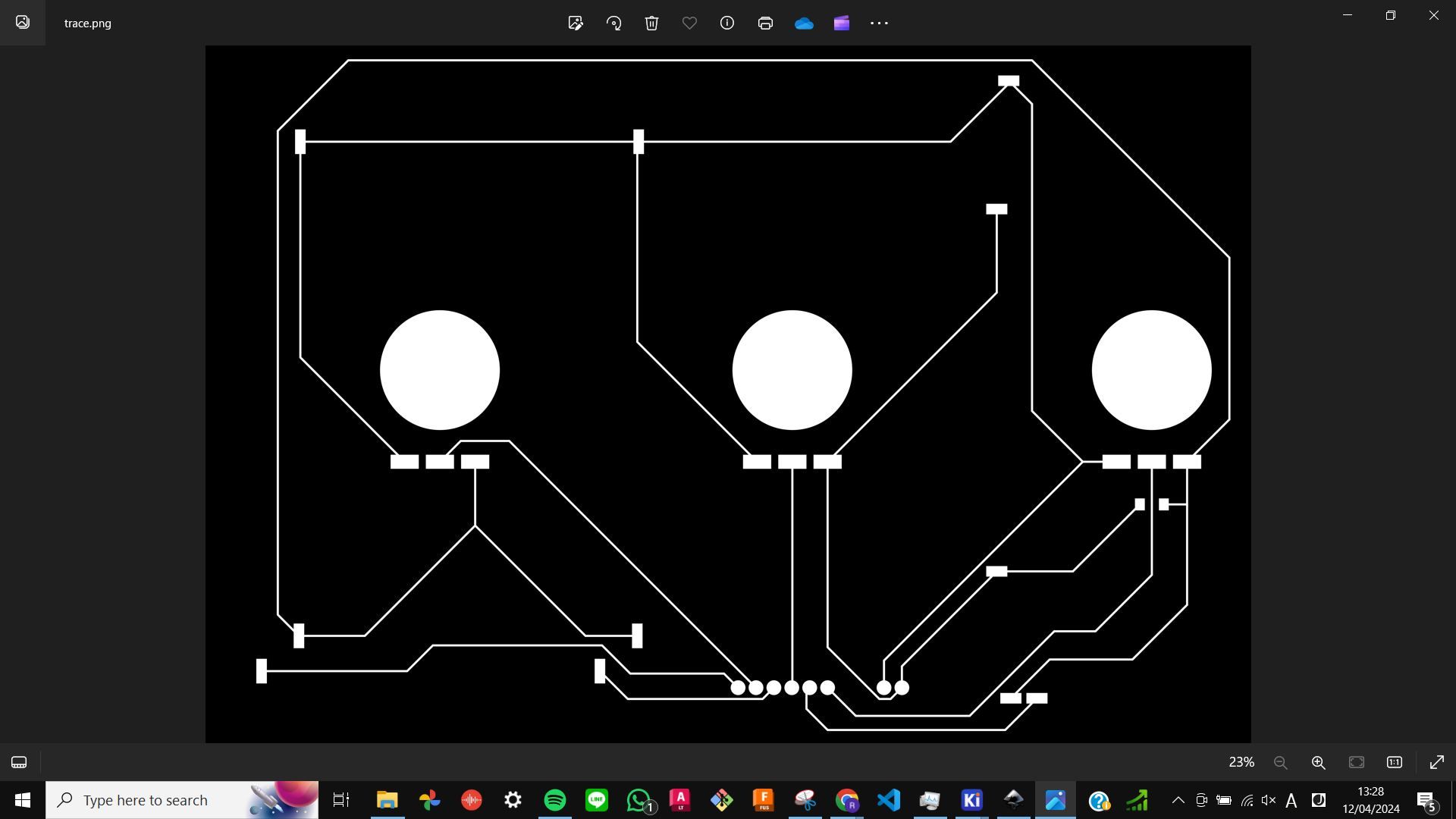
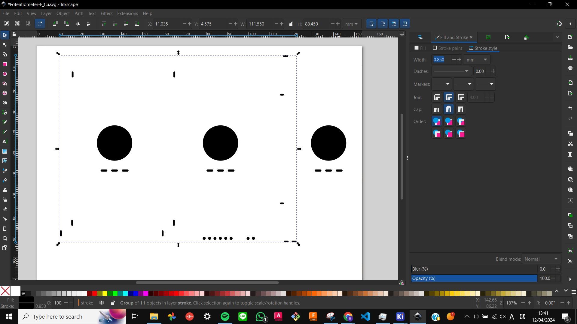
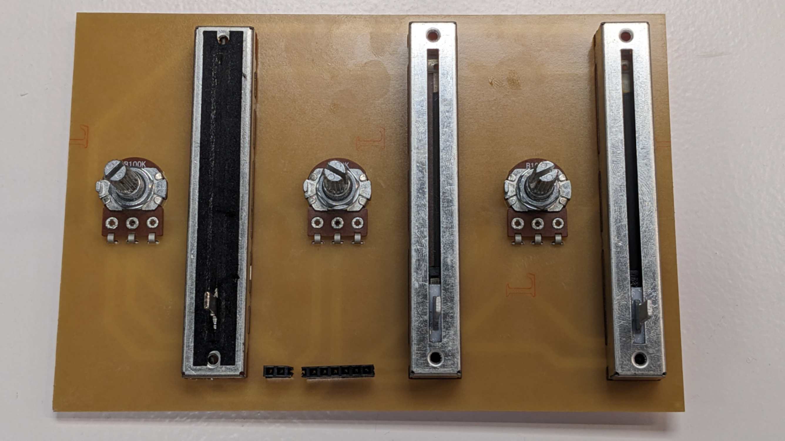
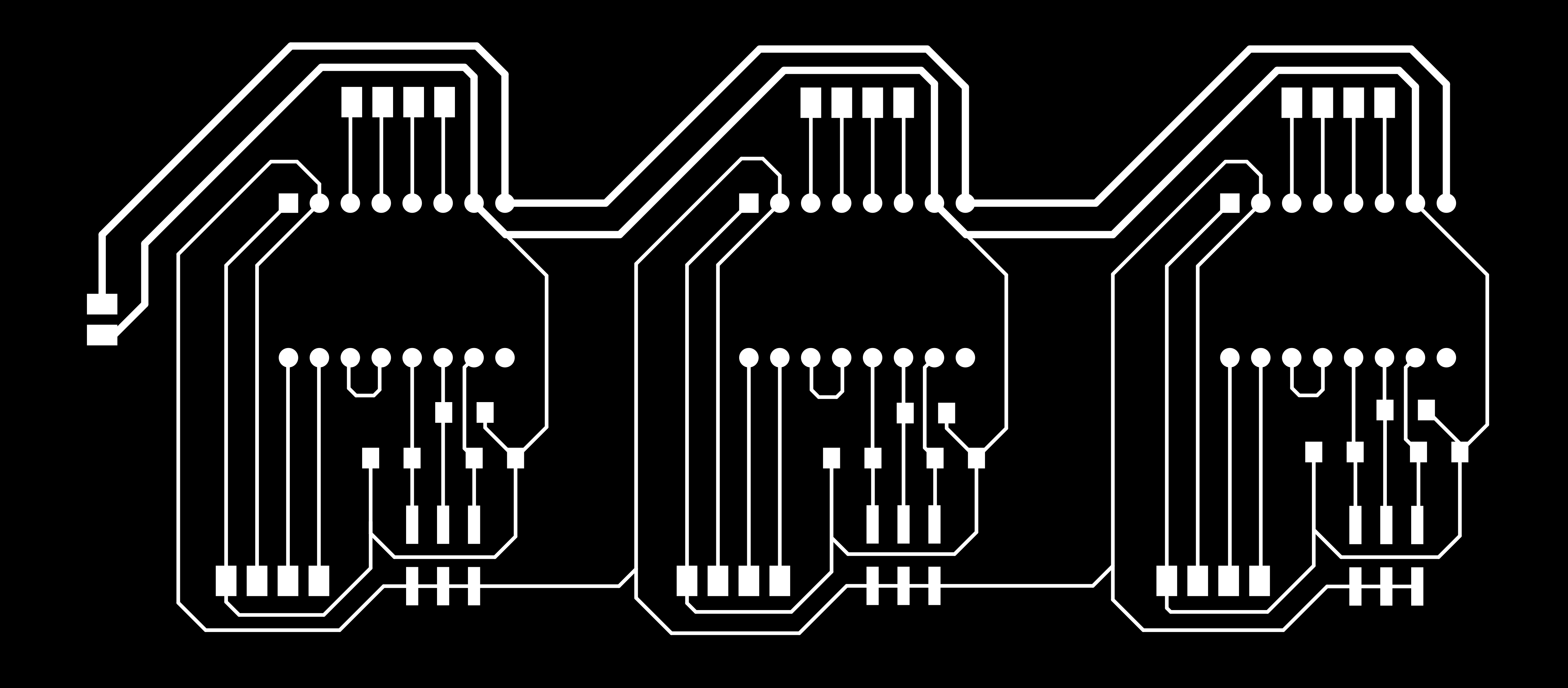
After that, I designed my PCB and milled it. I needed to be careful with the side of the PCB because the potentiometer will be installed from the back and it will be soldered on the front side. Also when this is in use the back side will be facing up, so I needed to get my head around the flipped design of this PCB.
After all, my DJ set-looking PCB is made. Something to remember, when I made foot print for holes I used tolerance around 0.1~0.2mm which was a perfect fit. But I could have made the footprint around the holes bigger to make it easier to solder.
FilesCustum_Riichi_symbols.zip
Custum_Riichi_footprints.zip
Potentiometer.kicad_pro
Potentiometer.kicad_sch
Potentiometer.kicad_pcb
Potentiometer-F_Cu.svg
hole.pngl
trace.png
hole.png.rml
trace.png.rml
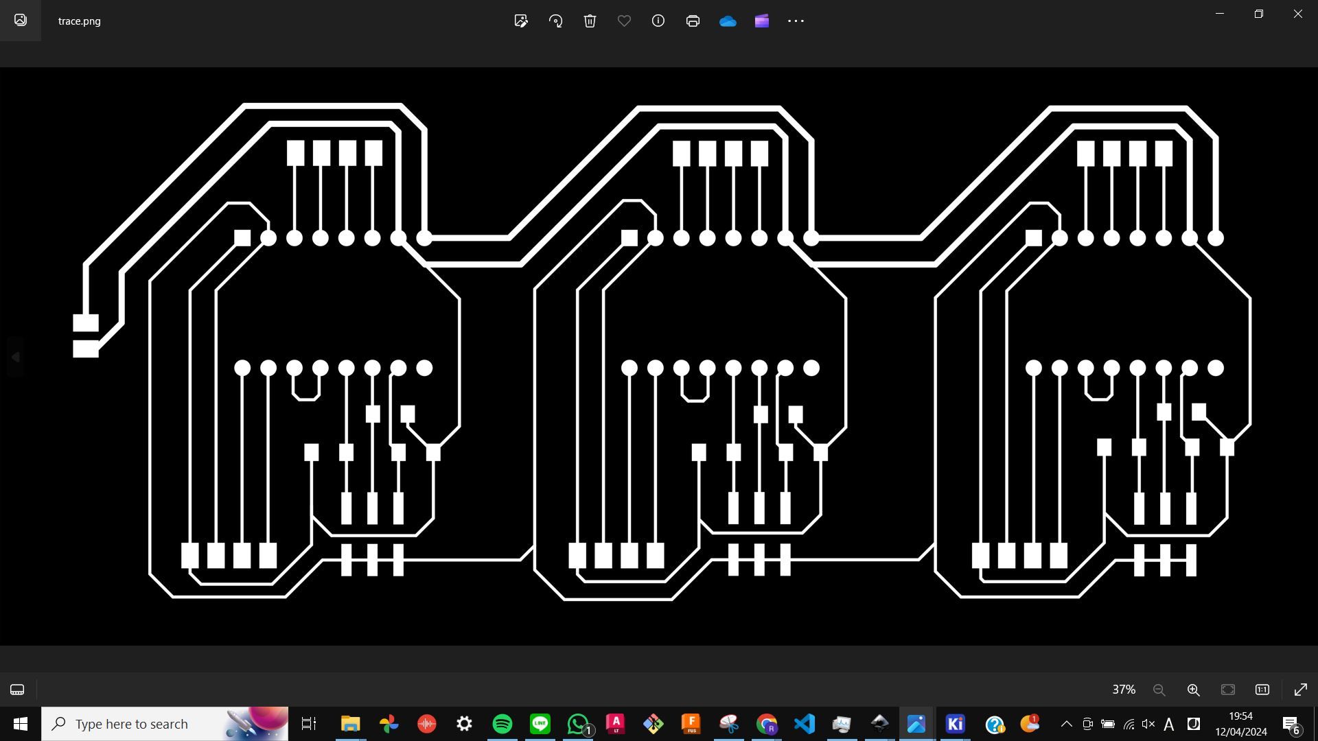
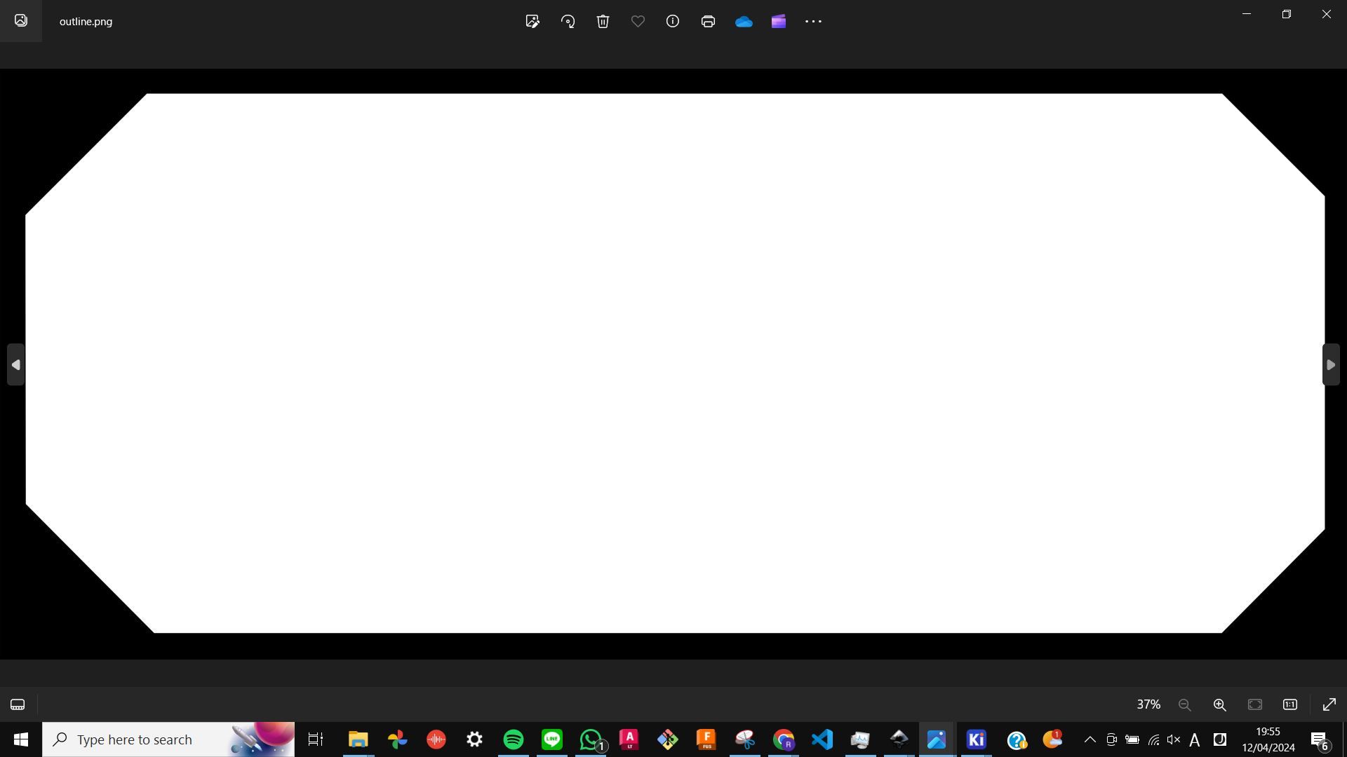
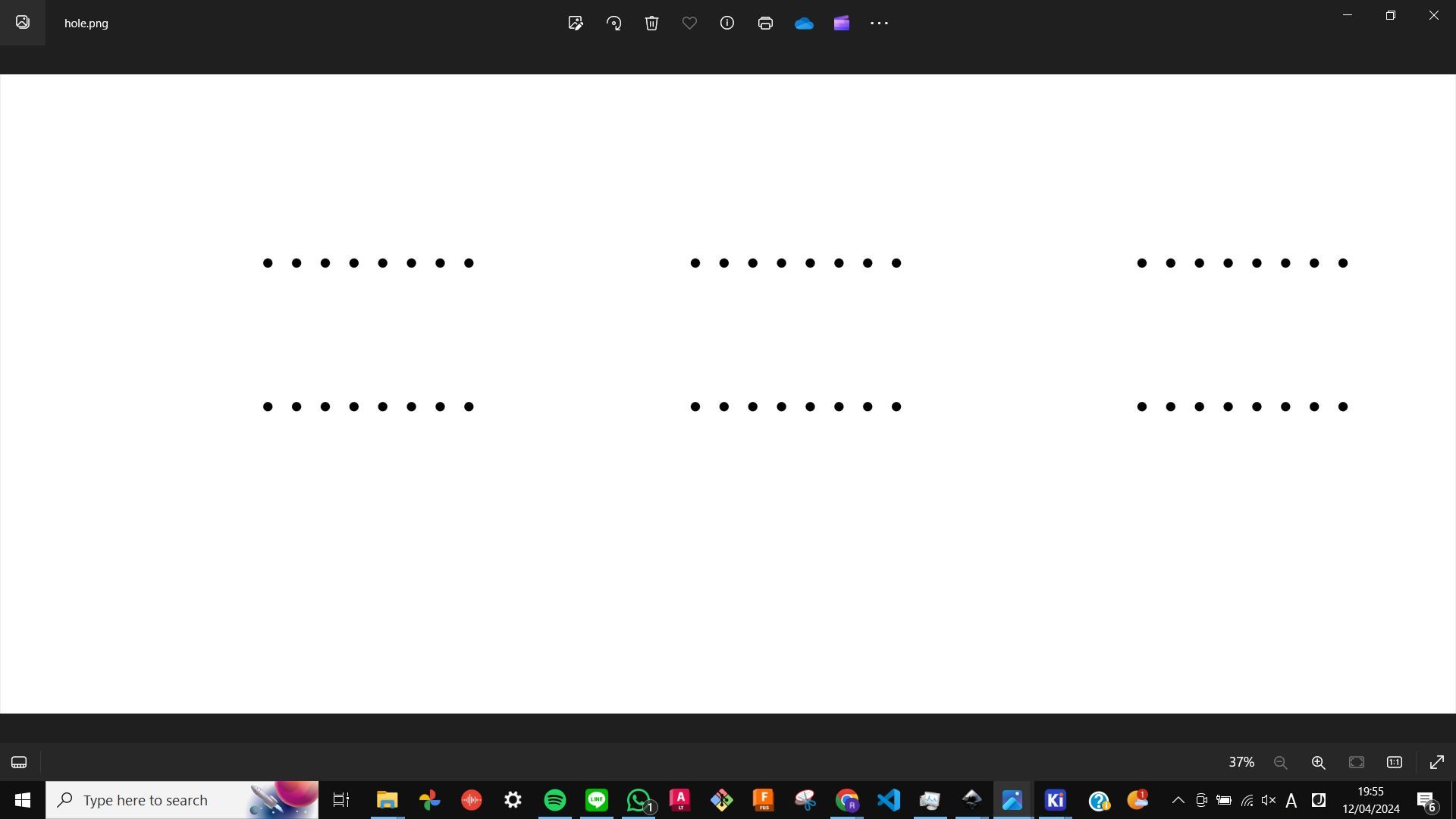
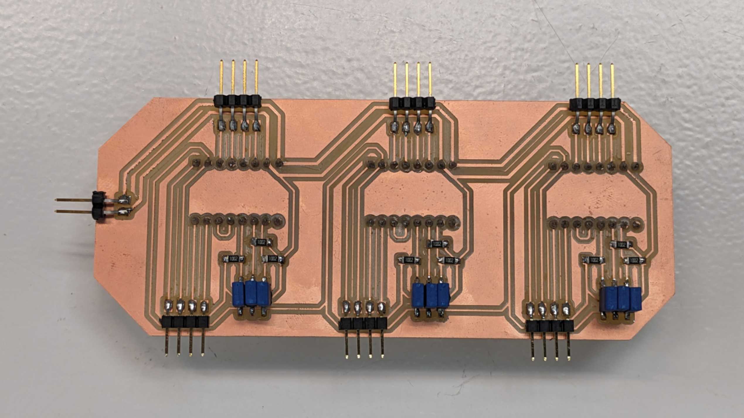
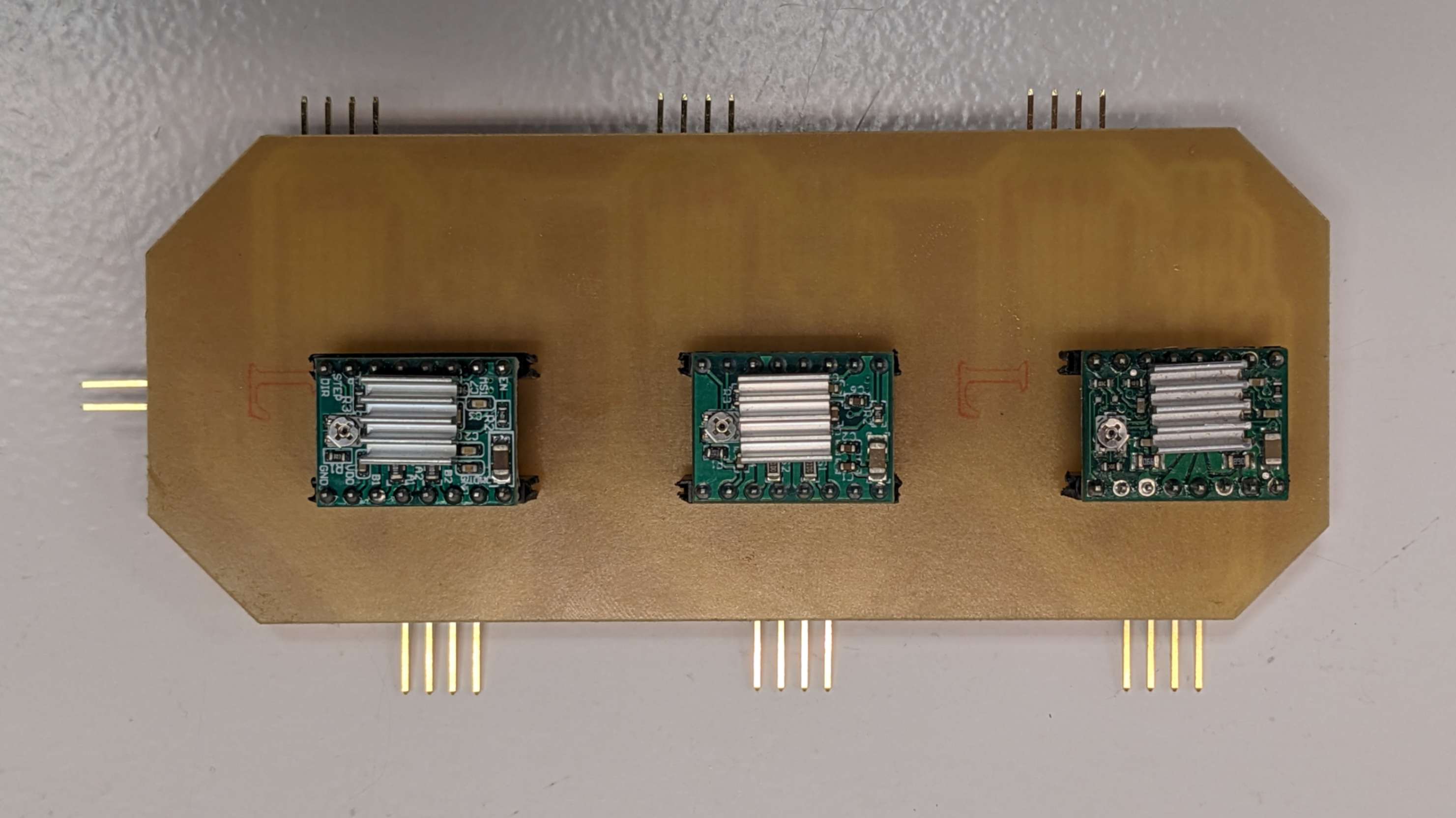
3 Stepper Motors Board
I wanted to extend my learning about stepper motors that I started in
Week 9 Output Device
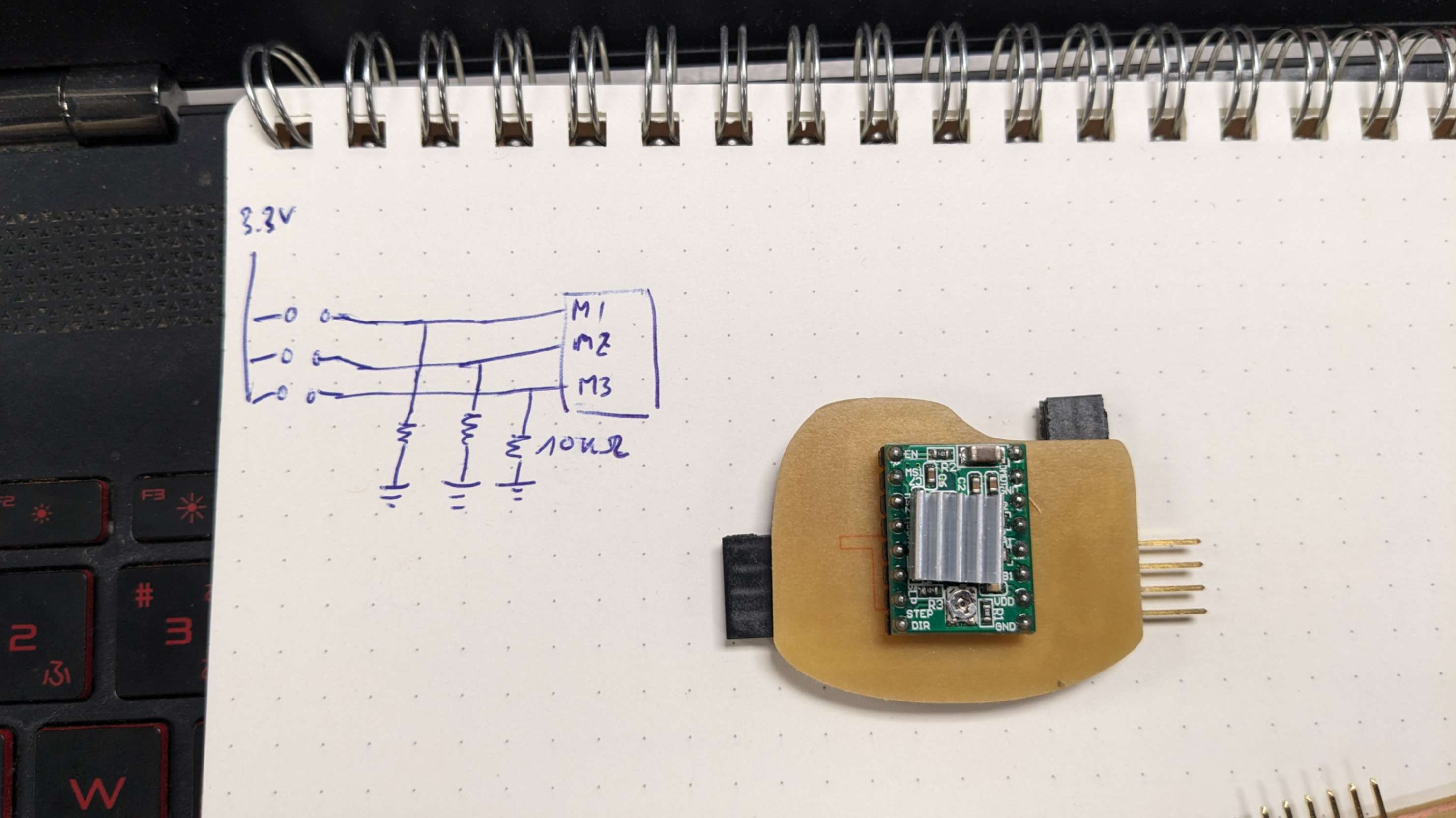
Same as last time, I am using 3 A4988 Motor drivers (one for each motor).
This time I wanted microstepping activated for all the motors. My tutor kindly explained how my connection should be for the micro-stepping pin (MS1, MS2, MS3). On the A44988 datasheet, there is a Microstepping Resolution Truth Table, which shows connections depending on microstepping resolution. L means LOW. H means HIGH. In my case, I wanted the maximum Sixteenth Step so I needed to connect all 3 MS pins to the voltage. My tutor recommended I connect the GND through a 10k register for each MS pin connection, to make these pins read GND when it is not connected to voltage and avoid floating pins in whatever case.
Files
3StepperMotors.kicad_pro
3StepperMotors.kicad_sch
3StepperMotors.kicad_pcb
3StepperMotors-F_Cu.svg
outline.png
hole.png
trace.png
outline.png.rml
hole.png (1).rml
.rml)
trace.png.rml
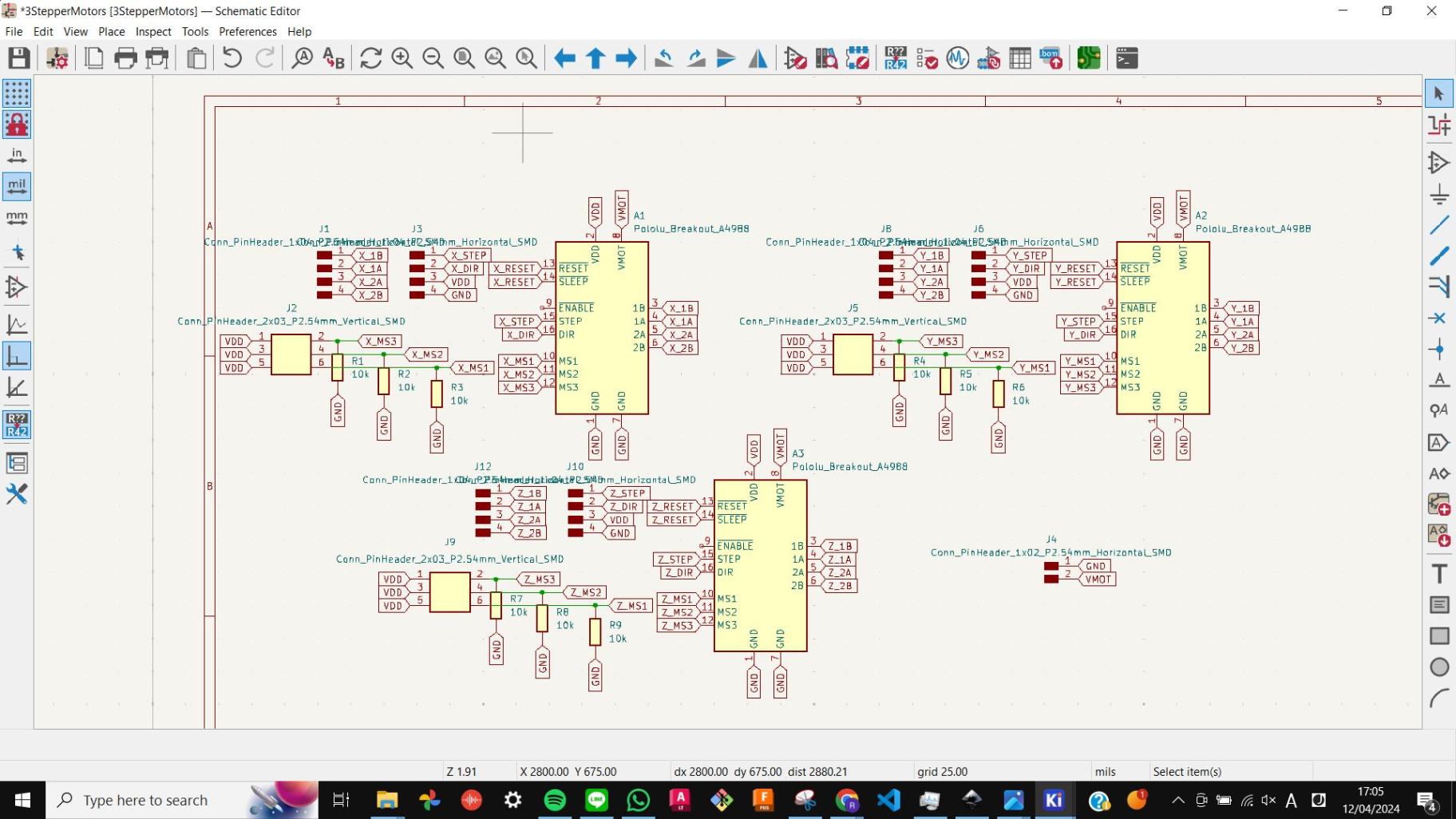
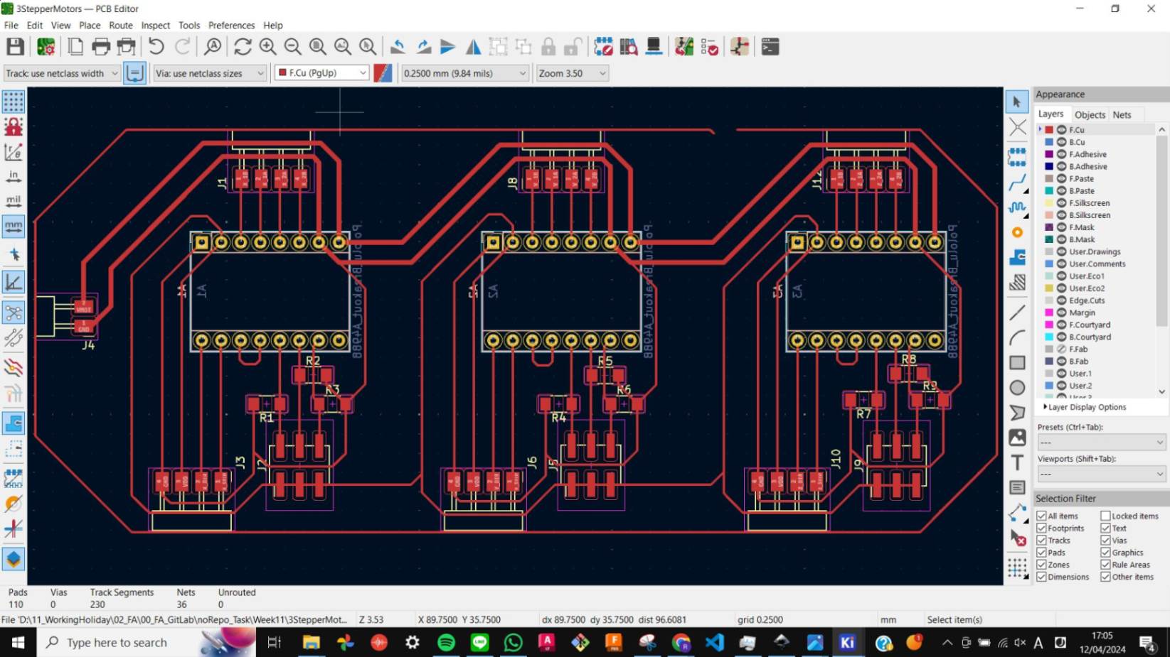
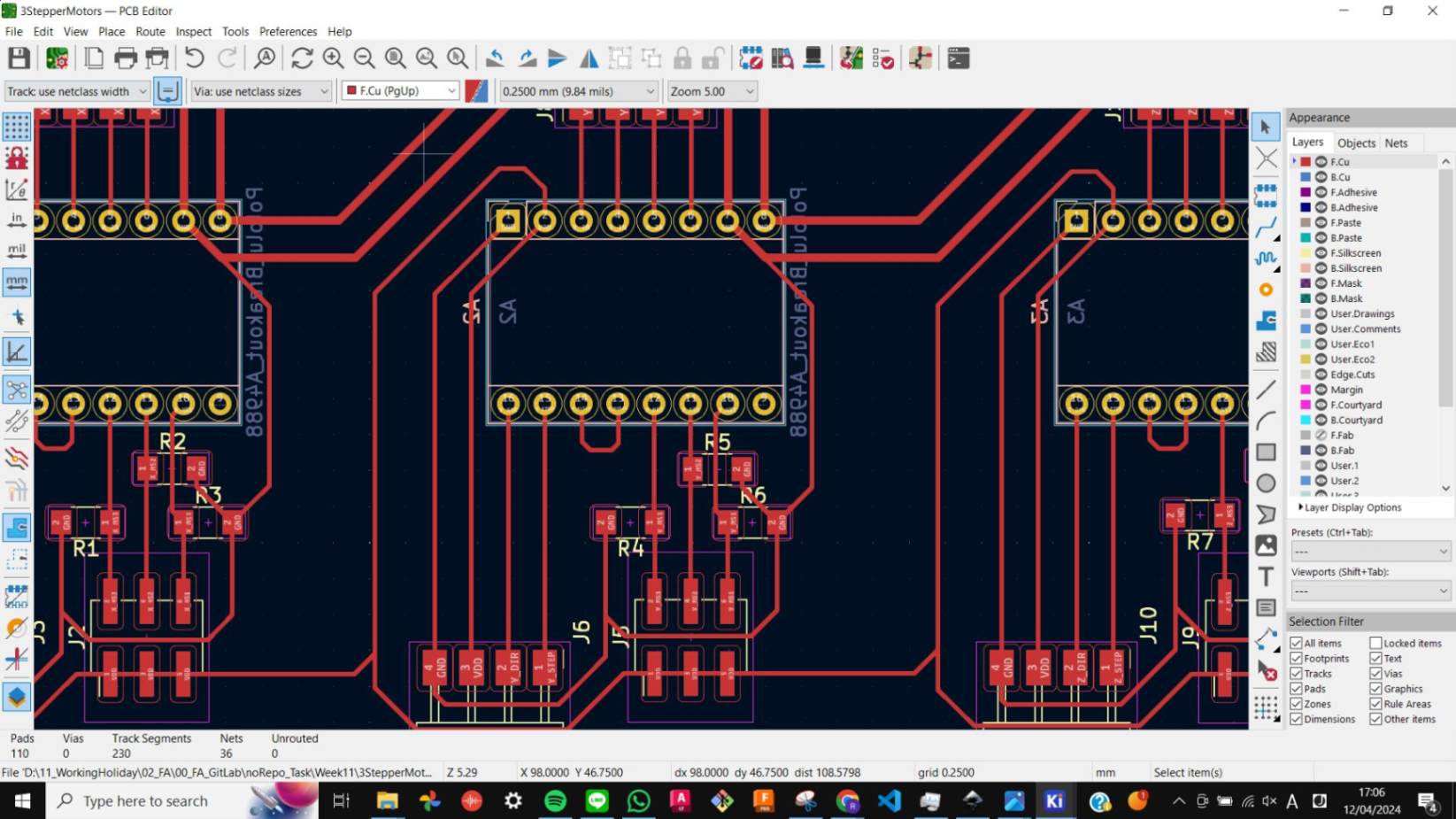
I designed another PCB in KiCAD. I followed the same step from
Week 9 Output Device
It was fairly simple and I am happy with the PCB design.
An important thing to remember is that VMOT, VDD and GND can be shared between motor drivers but DIR and STEP should only be connected separately per motor driver since I want the motors to move separately.
Reading Potentiometer
To read values from those analog potentiometer, I needed to make sure I connect them to analog pins of SAMD21 which are pin 2 to pin 7.
For the program, I used an example Analog Read Serial and modify little bit to quickly check the value from Slide potentiometer and Rotary Potentiometer.
Code_Potentiometer.txt
Then I used Color Mixer Example from Basics of Potentiometers with Arduino and I modified it in the way that will blink a LED with a value from a potentiometer.
Code_Potentiometer_Blink.txt
Then I combined a code for reading value of potentiometer and the code for moving Stepper motor which I used in Week 9 Output Device With the help from my tutor, I was able to understand the structure of each code. Then I decided to used rotary potentiometers to adjust speed of the motor and used slide potentiometer to change direction of the motor.
Code_Potentiometer_1StepperMotor_Speed-Direction.txt
Then I used same code to control 3 stepper motors mounted on Rota : a 3D paste printer with a rotational bed that we made in Week 10 Mechanical design & Machine design
Code_Potentiometer_3StepperMotor_Speed-Direction.txt
Step Without Delay
I was able to move the 3D printer using all the potentiometer, however rotary potentiometers were somehow all connected and making all the 3 motors affected at same time. Later my tutor told me that it is not a bag. It is expected to happened because the code is using delay to control the speed, and it was multiple by 3, which end up delaying 3 times more.
So my tutor advised me to look into
Blink without Delay.
It was little bit difficult for me to understand the concept of Blink Without Delay. So I used these YouTube videos to help me understand.
Understanding Blink Without Delay
Arduino Tutorial 5: Blink a LED without Delay
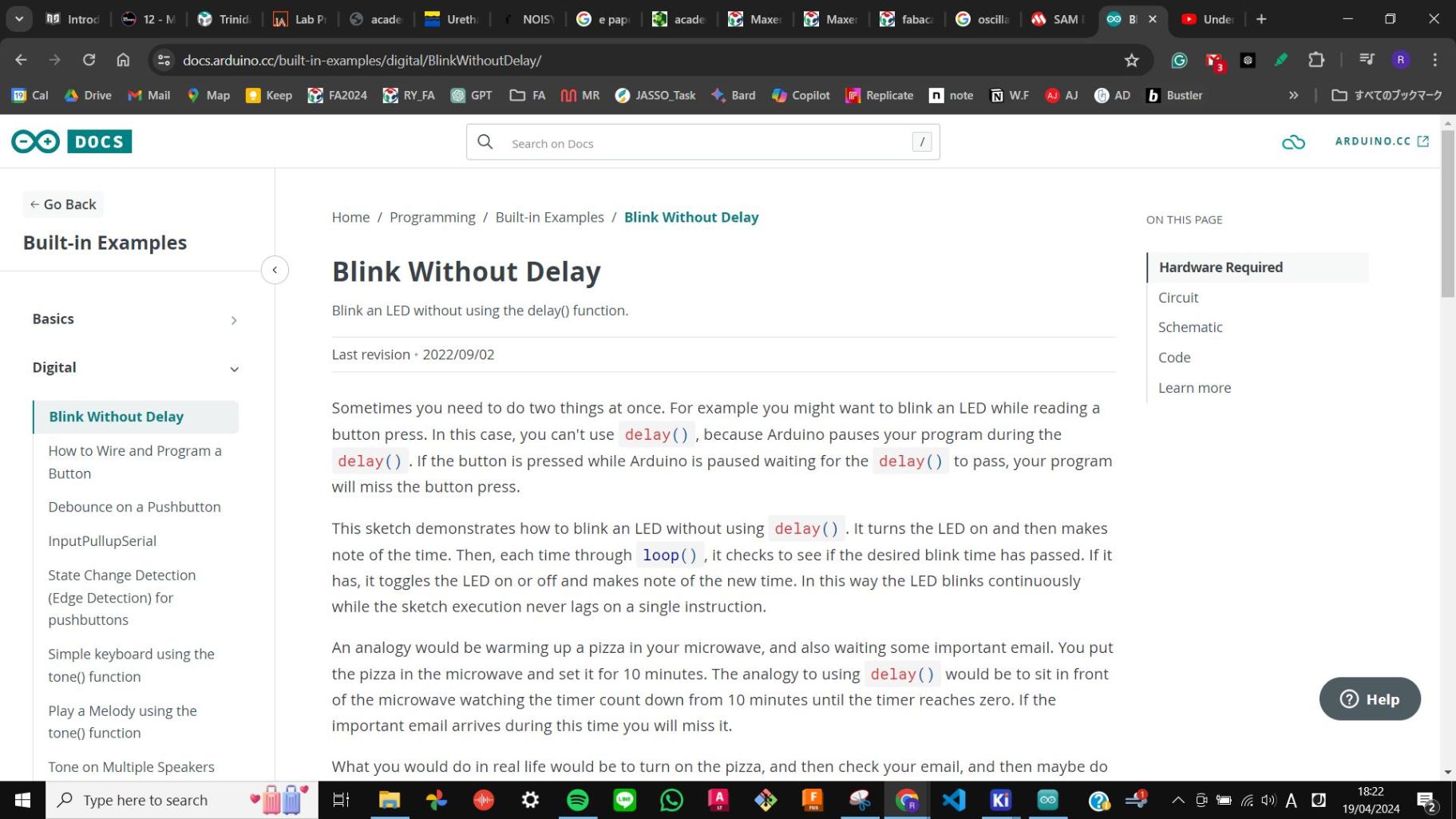
After getting some sort of understanding of the Blink Without Delay code, I combined the code with the code that moves a stepper motor at a constant speed. This time, I set the counting unit as Micros and the interval to 100 and then I replaced the delay with interval. As a result, I was able to move a steeper motor a step per 100 microseconds.
Code_StepWithoutDelay.txt
Step Without Delay + Potentiometer
Then I moved on to the next step. I simply combined the Step Without Delay code with the code that moves the motor according to the Potentiometer. As a result of this, I was able to change the speed of the motors with the potentiometer without delay.
Code_StepWithoutDelay-Potentiometer.txt
Step Without Delay + Potentiometer + 3 Stepper Motors
Lastly, I applied the previous code to 3 motors. To do this I needed to have three counting and interval separately so I added 2 more of the Step Without code. As a result, I was able to move multiple motors with different speeds for each of them.
Code_StepWithoutDelay-Potentiometer-3StepperMotors.txt
Video(.mp4)
W11_Step Without Delay + Potentiometer + 3 Stepper Motors_FA2024RY_compress.mp4
Afterwards, I used this result in the 1st iteration of my final project such as manually controlling a 3D printer. The documentation is on My final project page.
Thank You Always
Special thanks to my tutor Josep for patiently dealing with me as always.