Week 13
Networking and Communications
Fab Academy 2024
Riichiro Yamamoto
Dear My Friend
This week we got introduced to Networking and Communication. It is basically about the way of communicating between more than two microcontrollers. For example, Serial, I2C, Bluetooth, and Wifi. Especially I found it very interesting how wireless signals are done same principle but with different frequencies. I would definitely like to try wireless networking but for this week I kept things simple and quick because I wanted to develop more on my final project.
Hope you enjoy
Riichiro Yamamoto
Group Assignment
this week's group assignment was to send a message between two projects.
Here is the link to the group assignment page

I2C
For this week's assignment, I wanted to do a quick test of I2C communication, which I was introduced to briefly in a local class. I2C is a communication protocol that is used when communicating between more than 2 microcontrollers. I2C is a wired communication, it requires a specific pin such as SDA (for data) and SCL (for clock) to be connected between microcontrollers.
SAMD11 + SMAD21
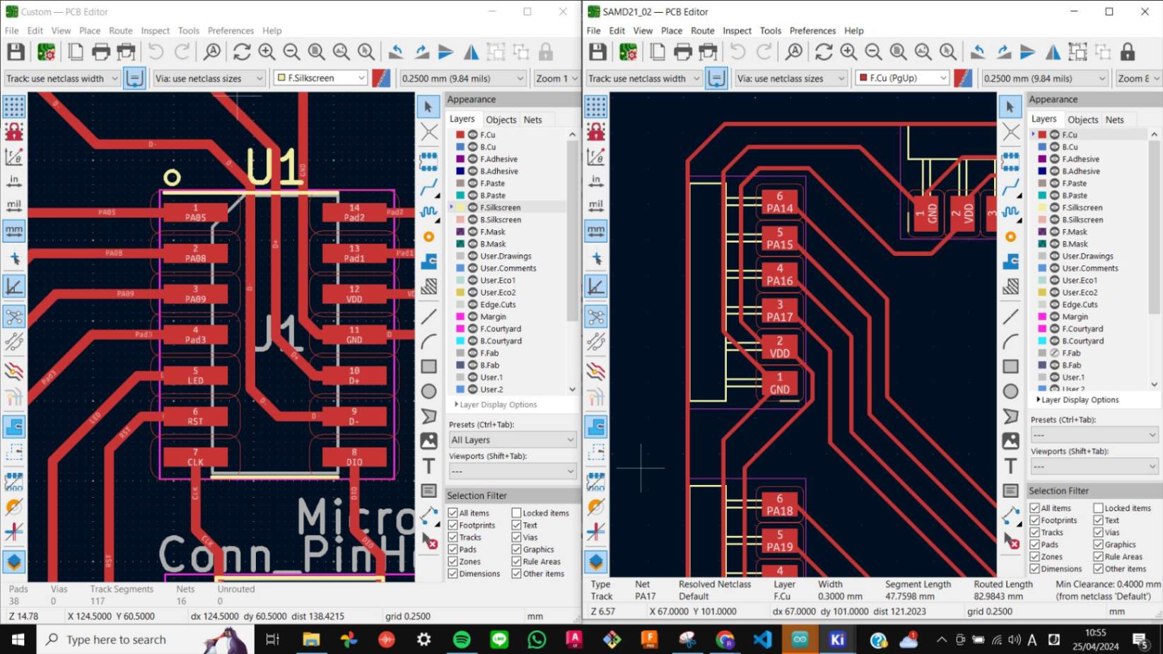
Initially, I wanted to use the SAMD11 board that I made in Week 8 Electronic Design and the SAMD21 board that I made in Week 11 Input Device
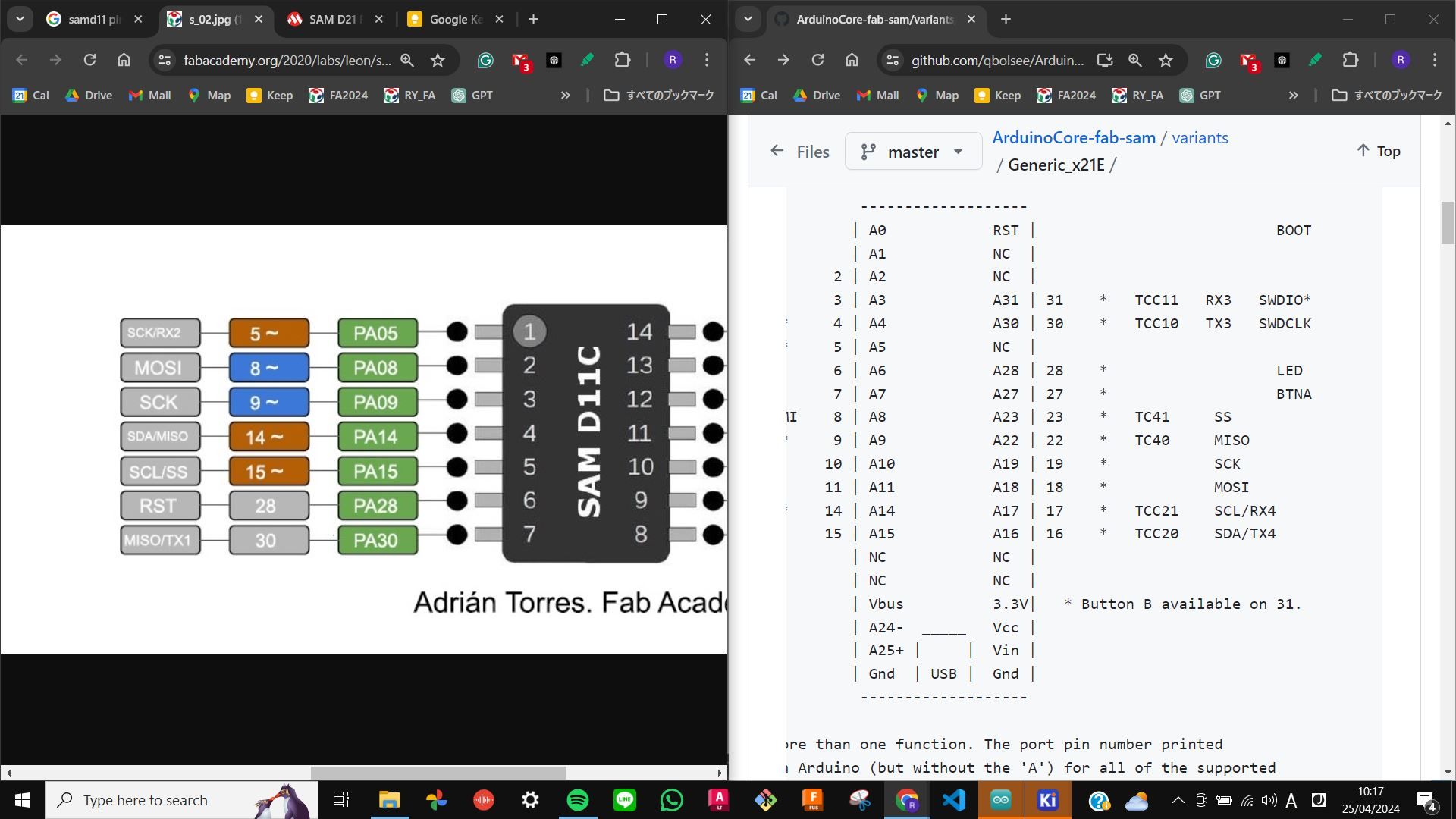
Since I2C is a wired communication, it requires a specific pin such as SDA (for data) and SCL (for clock) to be connected between microcontrollers. Therefore I needed to find out the SDA and SCL pin for SAMD11 and SAMD21. For the SAMD11, I used the pinout on the
I was advised to create a mold for the outer shape of the nobs and a cap that goes on top of the mold with a part that makes holes. SAMDino page. For SAMD21, I used the pinout on ArduinoCore-fab-sam page. Then I got to know that the pin 14 (SDA) and pin 15 (SCL) of SAMD11 and the pin 16 (SDA) and 17 (SCL) of SAMD21 need to be connected.
Unfortunately, my SAMD11 board did not have pins 14 and 15 out for connection. They were instead used for capacitive touch and LED.
Barduino + SAMD21
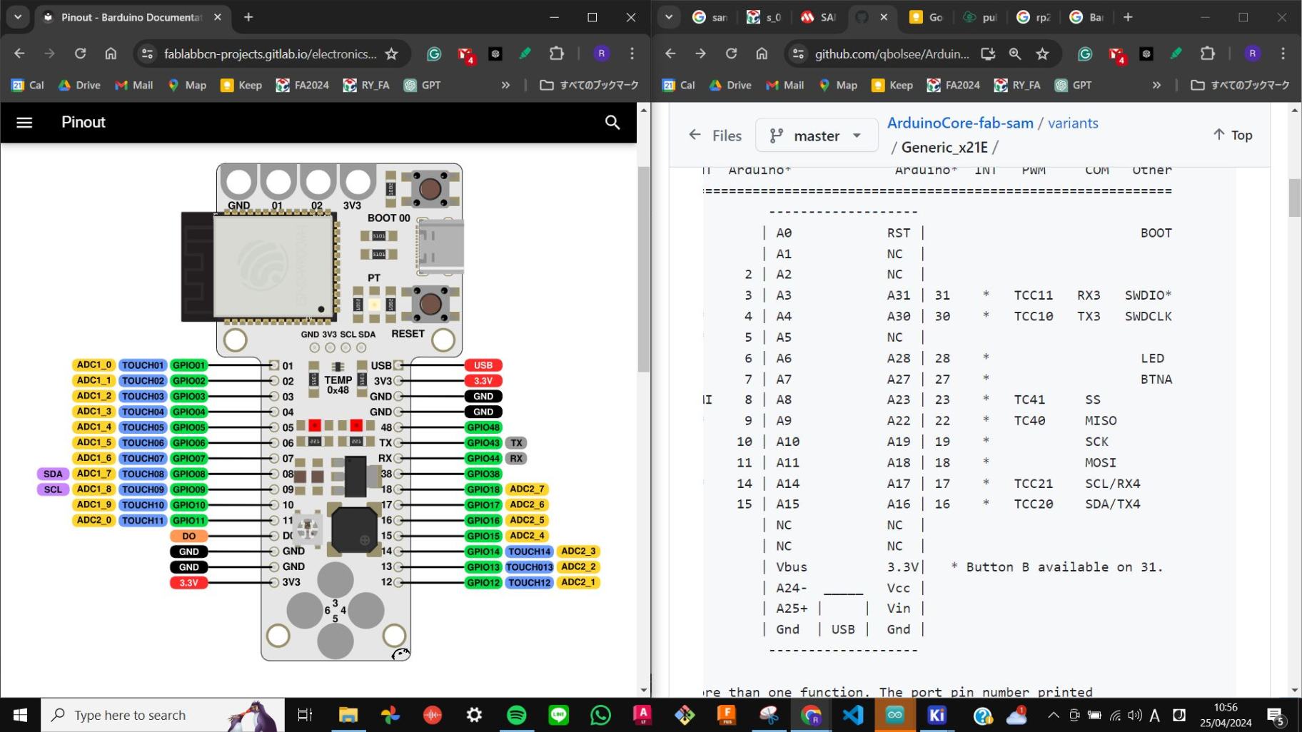
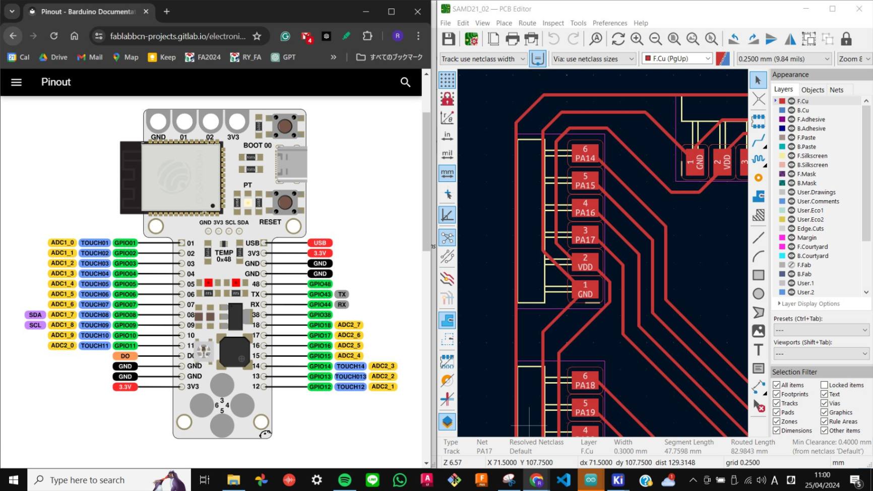
So I changed my plan and tried to connect Barduino and the SAMD21 board. For Barduino I checked the pinout on Barduino Documentation Then I connected both the SDA and SCL pins with two wires.
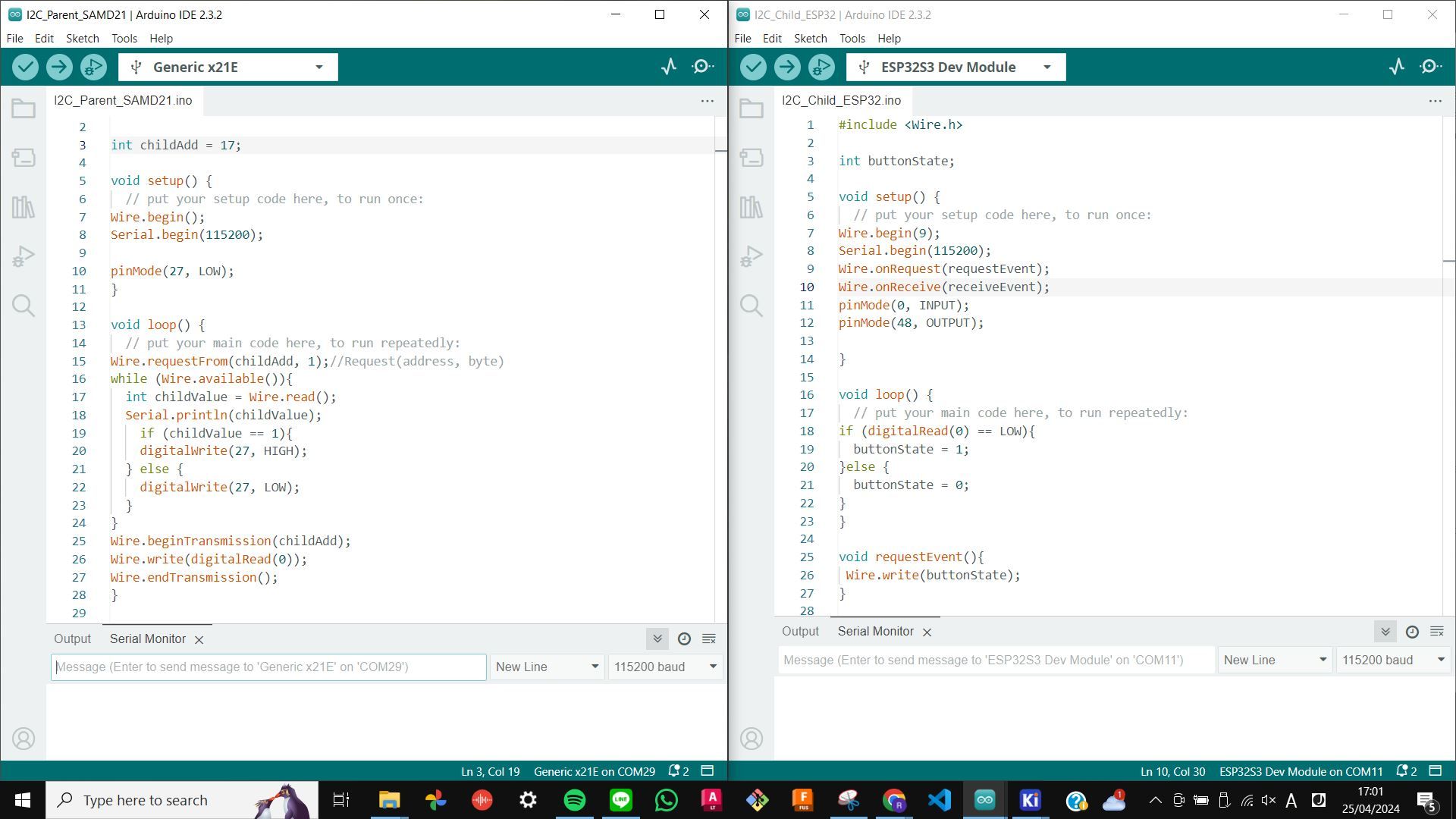
I2C Blink
For the program code, I used the code that I was introduced during the local class. This code uses Wire.h Library and it was used to blink LED by pressing a button between two Arduino. I modified this code to specify pins for SAMD21 and I made the LED on the SAMD21 board blink when the button on Batduino was pressed. In this case, the SAMD21 is the Parent and Barduino is Child.
I2C_Child_ESP32_Barduino.txt
I2C_Parent_SAMD21_Blink.txt
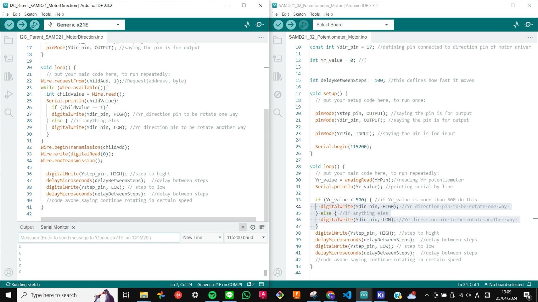
I2C Motor Direction
Then I moved on to connecting a motor to this I2C communication. I took some code from the code that I used to move the stepper motor in Week 9 Output Device and, combined with this I2C code. Instead of blinking LED, I changed it to motor direction, so that the motor direction flips while the button on Barduino is pressed.
I2C_Child_ESP32_Barduino.txt
I2C_Parent_SAMD21_MotorDirection.txt
Video(.mp4)
W13_I2C Motor Direction_FA2024RY_compress.mp4
After all, it was nice to know a little bit about all sorts of networking and communication, and be able to test I2C by myself. However, my final project does not require a lot of networking so I was rather focused on developing my 2nd iteration of the final project.