18 Project Development
This week's assignment is to complete your final project tracking progress.
1. Discovery
Ideation
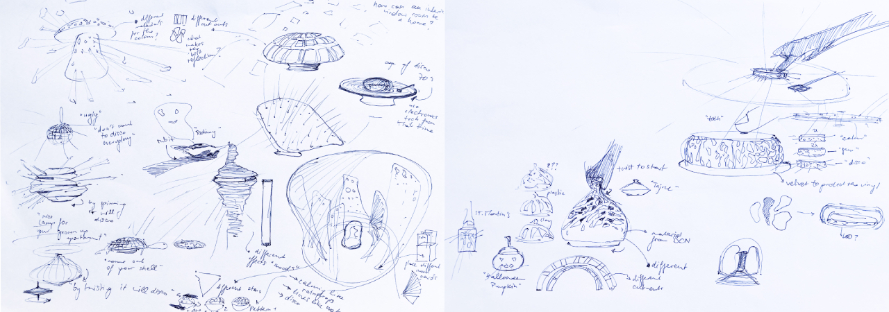
In my final project I would like to create a lamp that can transform into a mirror ball. Why couldn't a nice lamp for your grown up apartment adapt to your emotion and style of music? Sometimes you just want to dance in your living room, but mirror balls tend to be rather ugly.
During the next 19 weeks I want to explore different patterns, materials and ways of interacting with this lamp - why not twist it, have different tops from various materials, put it on a vinyl player, let it move with the beat of your favourite song or record your own pattern by tapping?
Inspiration
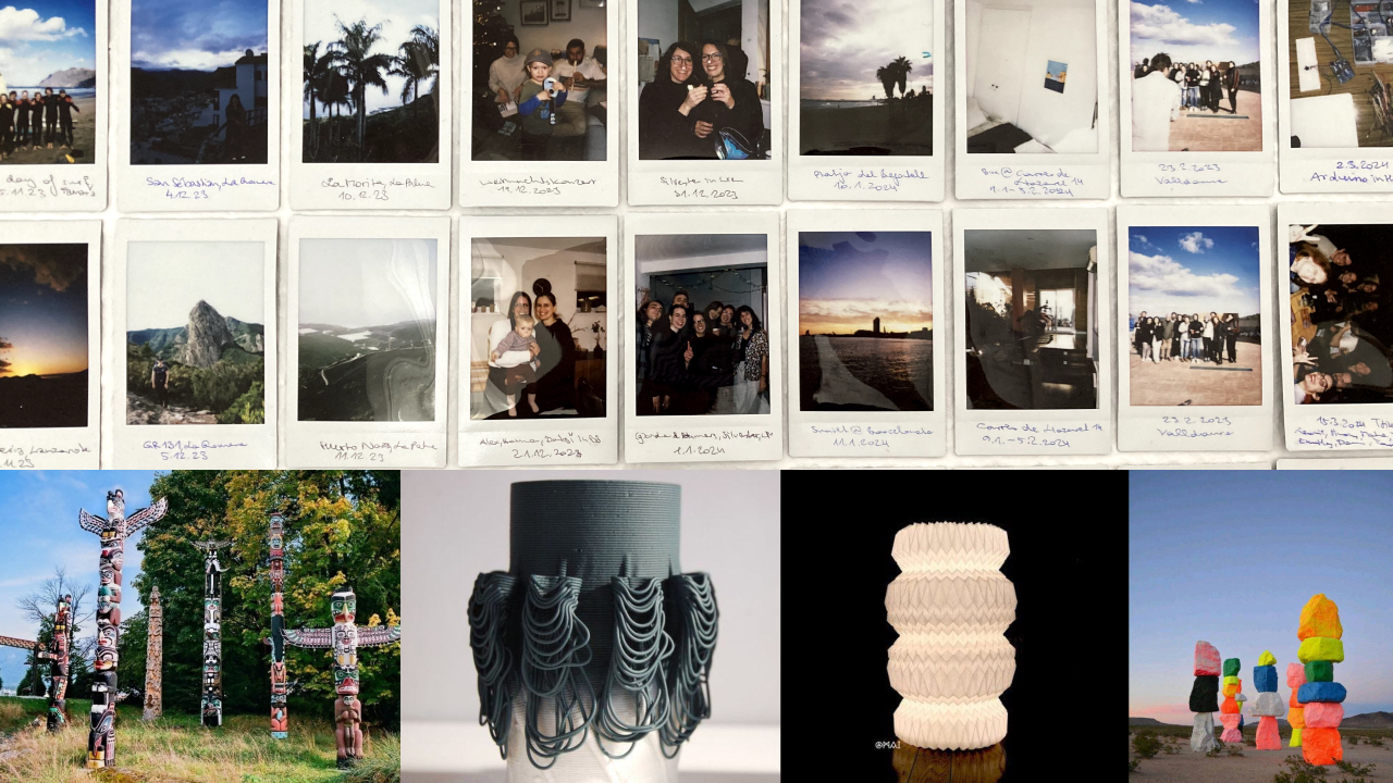
My final project serves me to explore the different aspects of art, design and fabrication during my sabbatical. I hope to find joy in my job as a designer again and make stuff with my hands. The idea of a lamp has very much to do with the expression and memories I am building during this year off. The idea of a totem pole telling a person's story has grown on my inspired by the indigenous art of the Pacific Northwest. Several artists have influenced my research and inspired the shape exploration in the past weeks, in particular: Udo Rondinone's Seven Magic Mountains, Alterfact's Elaboration Series and MAI's papersculpture 04.
Shape Exploration
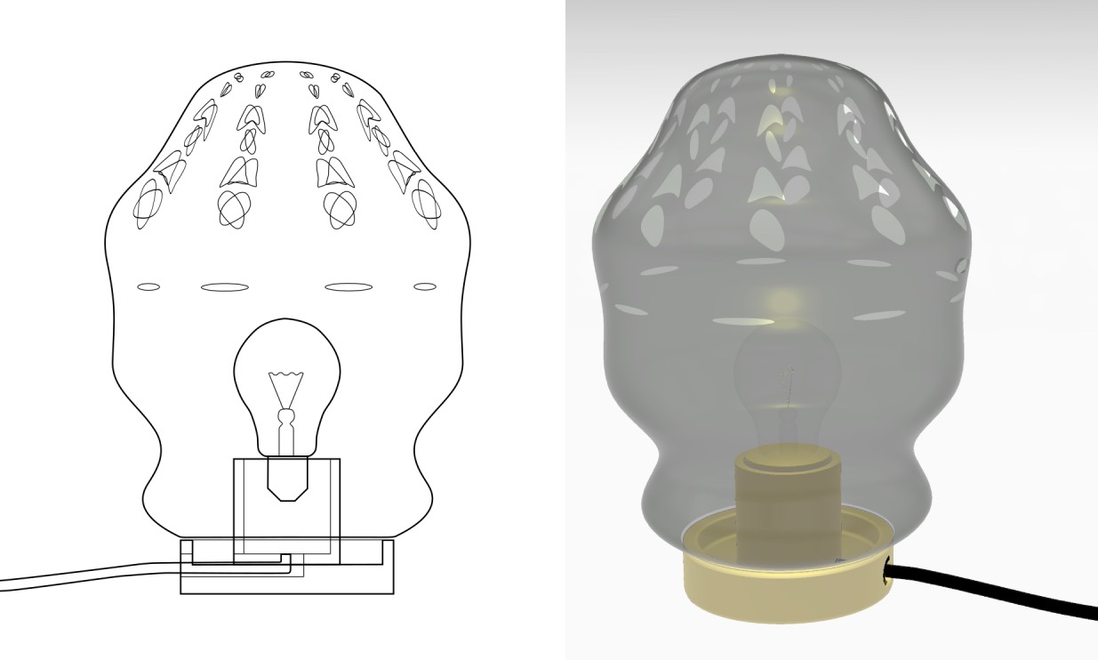
This week I built a light source base in Rhino to experiment with the different lampshade forms and cut-outs. I think I will need to build a realistic paper model in the upcoming days to understand the dimensions better. Personally I spent a lot of time on the 3D building process, and should start drafting a real 3D model as well to understand the proportions and cut-outs better.

Altough grasshopper is tough to learn and I wish my math was better - I really enjoy exploring the parametric shapes for the cut-outs of the lamp.

This week I am falling in love with 3-D printing clay - the process is a great mixture of manual and digital fabrication.
Concept Refinement

This project explores Jonathan Chapman's concept of an Emotionally Durable Design. With each stage/moment/memory in life the lamp growns with a shell added, resulting in a totem-pole like structure telling the story of a person's life. Each piece consists of a different material and emits light in another way.
Now that the concept is refined some more practical questions need to be answered in the next weeks:
- How many layers can be stacked?
- Which is the light source?
- Are there different light sources or just one?
- Which materials to use?
- Diameter of the shells?
- How is light emitted through the material and how much light?
- What is the input/output mechanism?
- Can each piece hold another piece?
- Can the material contain input mechanisms?
- How can the different layers be stacked?
- Do I have material restrictions? (e.g. clay is too heavy?)
Masterplan
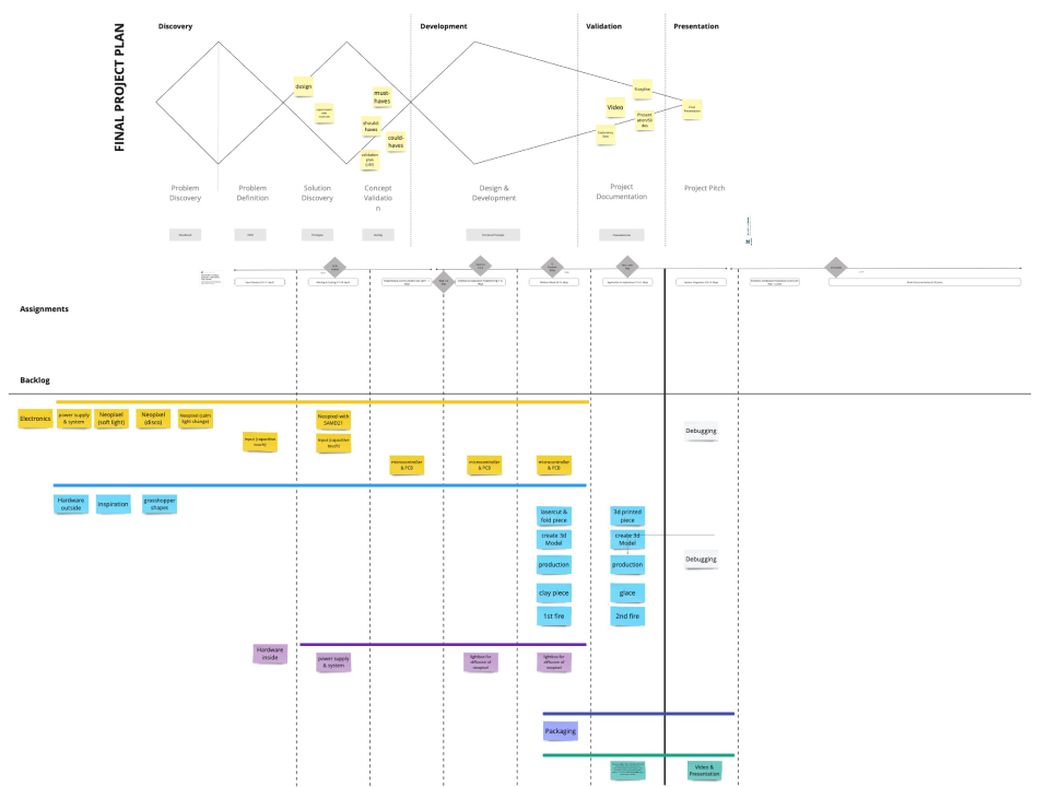
Please find my detailled masterplan in Miro. For my personal peace of mind I have given a priority to develop in spirals and iterate on the way:
- Electronics & Programming
- Shell Design
- System Integration
- Assembly
- Programming different lightmodes
2. Design & Development
Electronics & Programming
The main questions I had to answer in order to achieve the "hidden electronics" were:
Which microcontroller shall I use to power the neopixel?

After consulting our instructors I chose the SAMD11 to speed up the production process and keep it simple for the first version.
Which on/off switches will I use for the lamp?

To make a quick test I choose a breakout board with a switch button and a capacitive touch "button". I had tested capacitive touch during Input Device week and could use the code from this week to test.
I followed the electronics production process explained in week 04 and ended up with a simple board that was easy to use and test, please find the files for the first board iteration here and the breakout board here.
Power Supply via Magnets
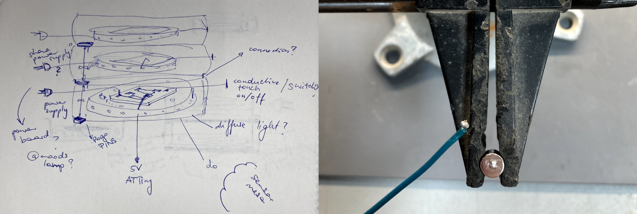
After analyzing several approaches with pogo pins, I decided to use magnets in order to use them both to transfer data, provide power and hold the shells together. I used Ralf Rogalevs' Easy Modular Lamp as a reference project to analyze and approach the connection. For a quick first iteration I used TamiyaGuy's magnetic holder and simply soldered the cable to the magnet. The magnets lost a little bit of their magnetism but are still working fine.
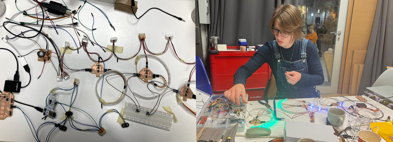
Power is shared!
Networking & PCB Iteration
The next step was to see if the I2C network works and SDA and SCL were transmitted via magnets as well - please find the complete documentation in
Networking and Communications week. I had a lot of issues with my board this week and eventually had to redesign and reproduce
the three boards. Thanks

I actually added the 5k Ohm resistor on this board, but had to change to a 0 Ohm resistor because eventually it was not necessary. Why the first pcbs were not networking will remain a mystery at this point. This batch works fine!
Programming
Child - Arduino Code Explained
First include all necessary libraries: wire.h for the I2C communication, Adafruit_Freetouch for the capacitive touch button and Adafruit_Neopixel for the neopixel strip.
        #include   //Wire library for I2C communication
        #include "Adafruit_FreeTouch.h"
        #include   //Neopixel library
Secondly include all the definitions for the neopixel strip and the creation of the strip object out of these definitions. Further the definition of the capacitive touch pin with it's settings. Please see Input week for the detailled explanation. I added the definition of the led pin to test if the board was powered and declared the ledState for the I2C events.
          #define BUTTON_PIN 2    //#=macro, int=integer
          #define PIXEL_PIN 8     // Digital IO pin connected to the NeoPixels.
          #define PIXEL_COUNT 20  // Number of NeoPixels

          Adafruit_NeoPixel strip(PIXEL_COUNT, PIXEL_PIN, NEO_GRB + NEO_KHZ800);
          //declare neopixel strip

          Adafruit_FreeTouch qt1(4, OVERSAMPLE_4, RESISTOR_50K, FREQ_MODE_NONE);
          //capacitive touch pin

          int ledpin = 9;
          bool ledState = false;  // bool can be true or false
In the void setup I start the I2C communication and the I2C events, as well as the capacitive pin and declare led and button pin. The neopixel strip needs to be started as well and I turn it directly off.
          void setup() {
            Wire.begin(1);//start the communication, this is just a number for address,
            not pins (1=child one), change for each child (needs a unique address)
            Wire.onRequest(requestEvent);
            Wire.onReceive(receiveEvent);  // define I2C events

            qt1.begin();
            pinMode(ledpin, OUTPUT);
            pinMode(BUTTON_PIN, INPUT_PULLUP);
            // button is HIGH by default, necessary to invert the code

            strip.begin();  // Initialize NeoPixel strip object (REQUIRED)
            strip.clear();
            strip.show();
          }
In the void loop I am measuring the qt_value and define the range for the button to turn off and on (600). If the button hits this value the neopixel strip will turn on and the ledState will be set true.
          void loop() {
            int qt1_value = qt1.measure();
            if (qt1_value > 600 && ledState == false) {
              strip.fill(strip.Color(252,100,0),0,PIXEL_COUNT);//orange
              strip.show();     // Update the strip to show the new color
              ledState = true;  // state of led is true= ON
            }
          }
The I2C request event will write a 0 or 1 whether the light is turned off or on.
          void requestEvent() {
            Wire.write(ledState);
          }
In the I2C receive event I am defining the communication between the different shells with an IF statement to turn off if another part is on.
          void receiveEvent(int x) {
            int lecture = Wire.read();
            if (lecture == 0) {
              ledState = false;
              strip.clear();
              strip.show();
            }
          }
Parent - Arduino Code Explained
Same as for the Child code I start with including the wire library for the I2C communication. Than I define an integer for each child in the network and the number of children in total communicating in the network.
          #include  //Wire library for I2C communication

          int childAdd = 1;  //add all the children
          int childAdd1 = 2;
          int childAdd2 = 3;

          int numChildren = 3; //how many chrildren are in the network
In the void set up I start the I2C communication.
          void setup() {
            Wire.begin();  //parent without address
          }
In the loop the parent requests the ledstatus from the children and coordinates the communication between them if 1 sends 1 turn off 2 and 3 with the turnOff function.
          void loop() {
            for (int i = 1; i <= numChildren; i++) {
              Serial.print("requesting from ");
              Serial.println(i);
              Wire.requestFrom(i, 1);  //Request(address, byte)
              while (Wire.available()) {
                int childValue = Wire.read();
                Serial.println(childValue);
                if (childValue == 1) {
                  //TURN OF THE REST
                  turnOff(i);
                }
              }
              delay(500);
            }
          }
This function defines the action that is triggered if a shell is switched on.
          void turnOff(int except) {
            for (int i = 1; i <= numChildren; i++) {
              if (i != except) {
                Serial.print("Turning off ");
                Serial.println(i);
                Wire.beginTransmission(i);
                Wire.write(0);
                Wire.endTransmission();
              }
            }
          }
2D and 3D Modelling
Shell Design
The goal for the shell design was to explore different materials and processes. For the first prototype I lasercut the base and one of the shells and 3-D printed in clay and polypropylene.
Lasercut Base

For the Lasercut Base I used 4 mm birch plywood to create a case for the parentboard and an entry for the cable coming from the AC/DC converter. This piece serves as the first line of four magnets to share GND, VDD, SDA and SDA. I used the kerf test to test which size would fit the 6mm magnets perfectly: 5.9 mm.
To cut the pieces I used our lab's Rayjet 500 with the following settings:
- Cut: Power (..), Speed (..), PPI/Hz (Auto)
Lasercut Shell

The lasercut shell is made out of white opaque 1mm polypropylene. I engraved the valley and mountain folds and cut the outer shape to achieve a glide reflection pattern.
To cut the pieces I used our lab's Rayjet 500 with the following settings:
- Engrave: Power (15), Speed (5), PPI/Hz (Auto)
- Cut: Power (25), Speed (3.5), PPI/Hz (Auto)
3D printed Shell (Clay)

The 3D-printed Shell is made out of black clay.
I used Grasshopper to generate a parametric curve and aligned these with circles in Rhino and used Loft to create a polysurface. The little hole for the button was created by hand.
To print the piece I used our lab's paste printer and the process described in 3D-printing week to generate the G-Code with Mamba and print with Repetier Host.
3D printed Shell (PETG)

The second 3D-printed Shell is made out of blue PETG.
I used Grasshopper to create an isocurve structure and again used Loft to achieve a polysurface. To create the hole for the button I used Boolean Difference and substracted
a cylinder.
To print the shell I used our lab's brand new Bambulab A1 printer. To slice the file I used Bambu Studio
with the default settings for Basic PETG and the special mode Spiral vase, since I just wanted a single layer of material.
System Integration
The next step was to get a hold of my cable mess - please find the complete documentation in
System Integration week. I had a lot of "aha" moments during this tasks. Thanks
Assembly

The assembly turned out to be one of the trickiest parts of the projects. Here is a condensed list of my lessons learned in the process:

- check tolerances on all 3-D printers used
- prototyping is great - try to reduce quality for a faster print or just print one part
- calculate extra material for folded polypropylene
- hot glue is your best friend
- don't put clay pieces on top of each other in the kiln
- soldering cables is best done with four hands
- keep an eye on shrinkage of the clay
Programming different lightmodes
Turns out the SAMD11 was not the best choice for cool lightmodes, because of its limited memory - for version 0 I simply changed the RGB values in the child code.
Final Prototype and Files
Please see the final prototype and files on the Final Project Page.