04 Electronics Production
This week's assignment is to characterize the design rules for our node's in-house PCB production process in the group assignment, document the workflow for sending a PCB to a board house and make and test a microcontroller development board.
Group assignment: Design rules for in-house PCB production
The documentation for our group assignment from the Barcelona node can be found here.
Lessons Learned
- pay attention with the 1/64" drill mills, but you can still touch them
- choose a less busy day in the lab to solder in peace
- check the multimeter settings carefully, there is no universal design
A Quentorres PCB board
This week's goal was to produce a Quentorres printed circuit board, that was designed by Adrián Torres during the instructor's bootcamp 2024 and will serve as a base for the electronics design week.
1. File individualization

Initially I added a little bug to the .png file of the Quentorres with photopea. I was already considering the outline cut and turned the bug several times around, to avoid it being cut off. Since some of the components were arranged slightly different I used the files provided by our local instructors.
2. File preparation with modsproject.org
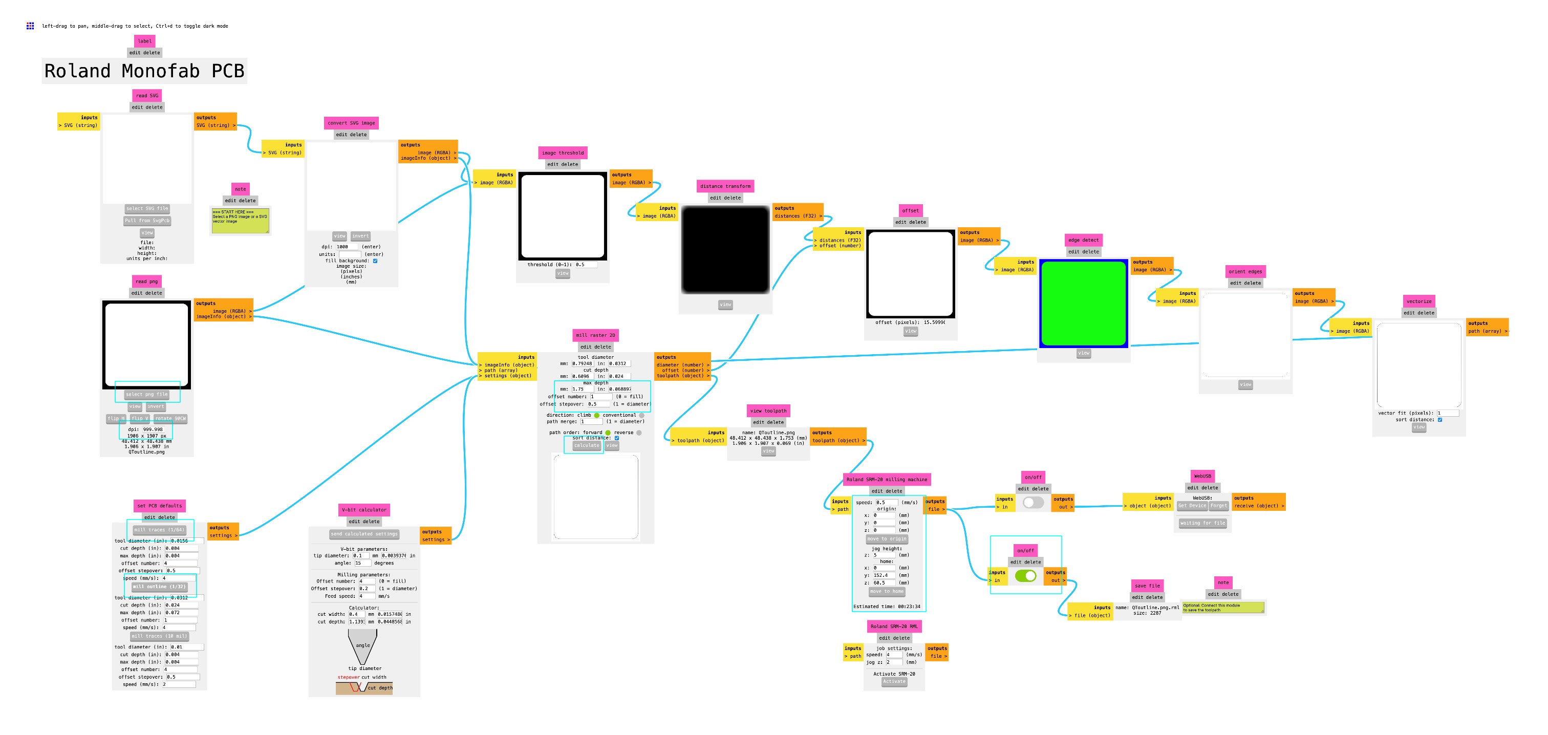
The second step was to prepare the .rml files with modsproject.org for the Roland SRM 20, our lab's PCB milling machine.
To select the right presets I opened programs/open program/Roland/SRM 20 mill/mill 2D PCB and prepared the files in the following order: traces, holes and outline.
I uploaded the .png file and first did not check the DPI settings in the upload section. For this reason I had to redo the files again, since instead of 1000 DPI it was orginally set to 999,967.
The next step was to choose the drill mills: traces (1/64"), holes and outlines (1/32"). Once selected the mill 2D settings will calculate the right settings
automatically, with only minor adaptations: For traces an offset number of 4 is sufficient, keeping an offset of 0 will cut away the copper all the way, which would take much longer.
To check for offset errors I used the View mode.
On our lab's machines the recommendation is to set the max depth to 1.75 for holes and outlines, which differs from the calculation, but preserves the base plate.
If you hit calculate at this point the file will be downloaded - it's better though to wait until all settings are done.
Continuing with the machine's settings of the Roland SRM 20:
speed: traces (3mm/s); holes (1.5 mm/s); cut (0.5 mm/s)origin: will be set on the machine (0/0/0)jog height: 5home: x/y doesn't matter, z default of 60 mm is fine
Finally choose the save file option and hit calculate to download the .rlm files and copy them to the IAAC cloud to be able to access them from the laptop
connected to the machine.
Here you can find my .rlm files: Traces, Holes, Outline
3. Milling
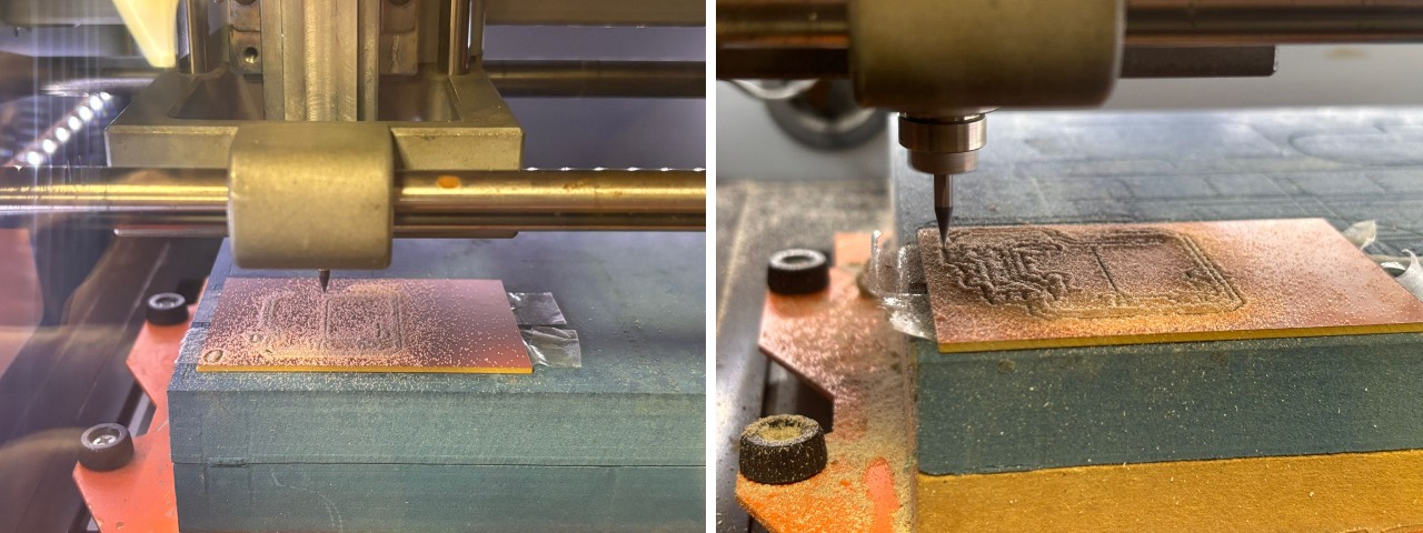
1. Fix the board in the milling machine with double sided tape. I used a little bit more tape on the edges to avoid bumps on the board itself and cleaned the base off old scraps.
2. Set the right end mills. First I prepared the 1/32" end mill for the traces and had to change it. The general rule of thumb is to cut traces first, than holes and cut the outlines at the end.
3. Close the lit and start the machine.
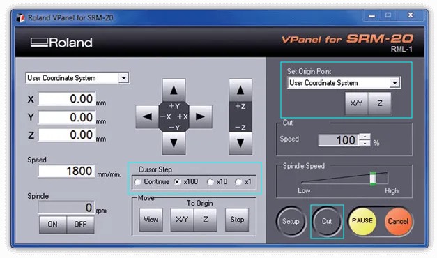
4. Open V panel on the installed computer and set the X/Y origin by eyeballing the lower left corner. Keep in mind that the machine has a little safety offset in both directions.
5. Set Z origin by moving slowly close to the board in 100 steps and 10 steps until you almost touch it. Than open the machine hold the end mill and gently move it down until it touches the board and set the Z origin on V panel. Than right away move Z up at least 5 mm again or the board will be scratched. Personally I would recommend to not have coffee before this step to have very steady hands.
6. Move X/Y to origin and open the cut menu. Delete all files and load file. It needs to be downloaded from the cloud first.
7. Hit output and the cutting starts. Make sure that the computer has no automatic resting time. My file paused and restarted from the very beginning
when the resting time appeared. Thanks
8. Repeat step 2-7 for the holes file and outline file. Don't reset Z for the outline file and don't change the X/Y origin else the files won't match anymore.
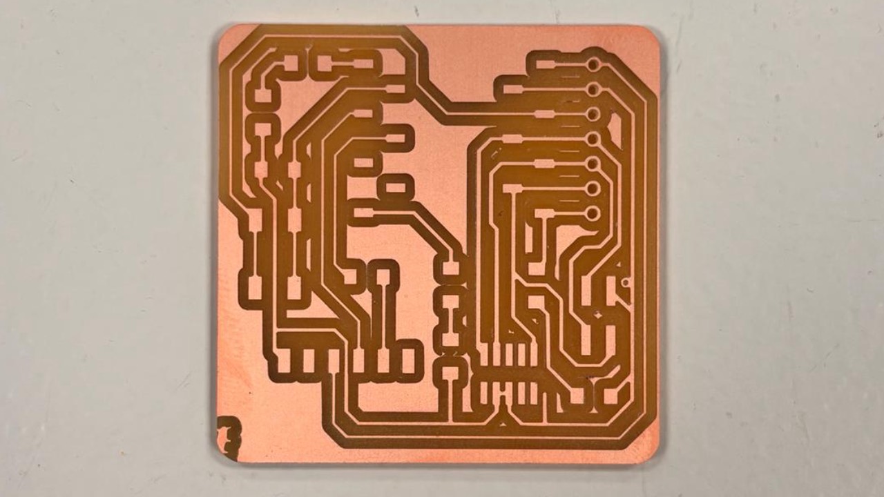
Eventually the little bug was cut off, so next time I need to position it better.
4. Soldering
I had never soldered before, so I took some time to understand the components before and drew the board to understand, where I needed to place the different elements. Than I wrote a "shopping list" and collected the components from the lab's deposit, sticking them on a little piece of paper. Make sure to double-check before soldering though.
Soldering workflow
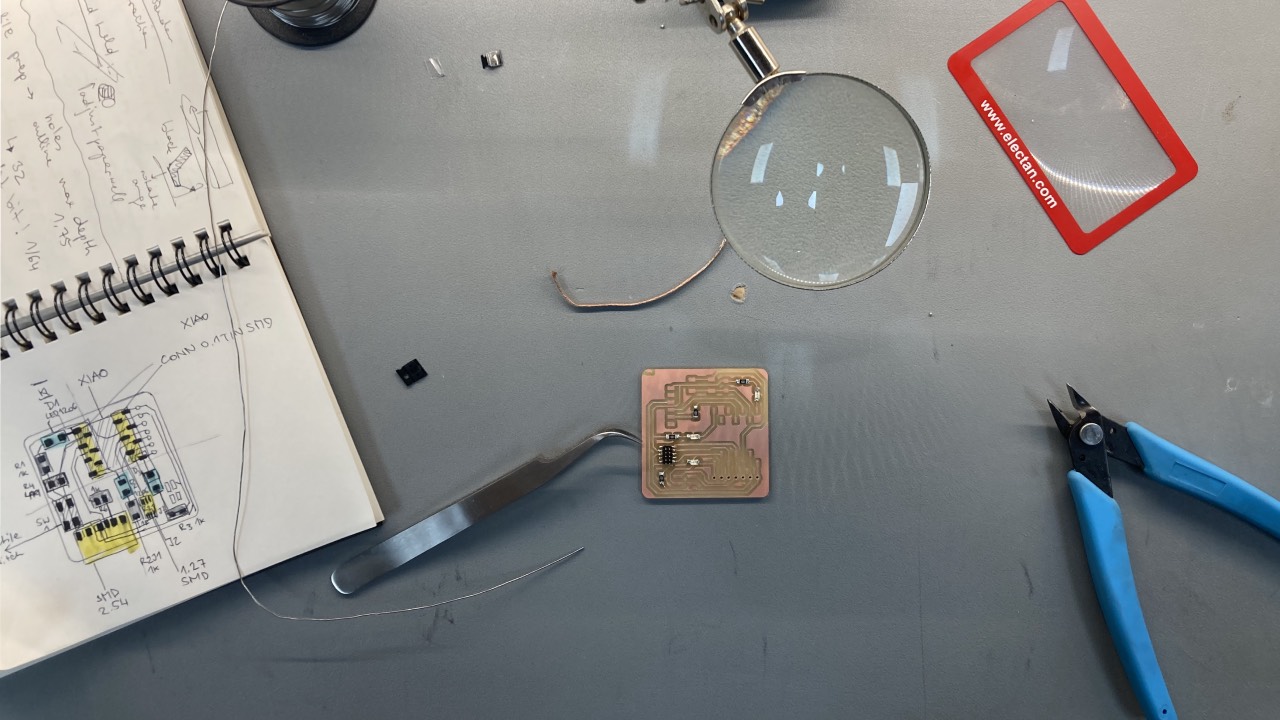
On our instructor's recommendation I started soldering the SMD 1.27 and placed solder on all 8 positions. First lesson learned to place the component before. So I used the copper braid to take of all the solder again and place the component first and solder each contact step by step.
For the following components I placed solder on one contact, placed the component, reheat and solder the second contact. Being a newbie I checked each component's connection after soldering with the multimeter.
It took me quite some time to find a good way to place the solder on the contact without bubbles on the wire, but eventually found the heating the copper contact first worked best for me. Practice really seems to be the key to success here. Personally I couldn't get used to working with the magnifiying glass yet, but preferred working without it.
I continued soldering the LED's (keep the right direction in mind !), resistors and finished with the bigger components. I choose the bent connectors for the SEED STUDIO XIAO RP2040 first and changed to the straight ones. To solder the XIAO to them I used a breadboard to keep it steady.
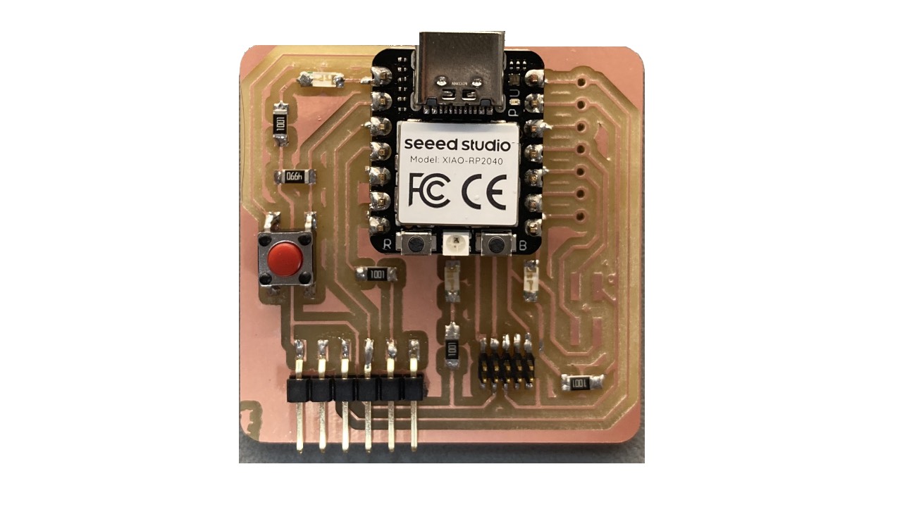
For a first time solder exercise, I am quite happy with the output. Thanks to everyone that was there holding my hand in the lab on this one!
5. Use as a hello board
To follow the 4 Step instructions I first had to download the Arduino program.
Open the Arduino program
I entered the provided link: https://github.com/earlephilhower/arduino-pico/releases/download/global/package_rp2040_index.json on Arduino IDE/Settings/Additional Boards Manager URLs. Obviously everything works
just slightly different on MAC.
Boards manager
I downloaded the Rasbperry Pico Pi RP2040 by Earlephilhower under Tools/Board/Board manager, which failed the first time, but worked on the second try.
Configure the Arduino IDE for the Seeed Studio XIAO RP2040
I actually had some trouble connecting the board to my MAC. Initially it would not appear and show that in the Arduino program that it is not connected. I tried to reset it with holding the R (reset) and B (boot) button at the same time, but that didn't work either. I tried the instructions Arduino suggests on it's platform. Since that did not work, I researched a little bit more and eventually the recommendation from the Arduino forum to turn off Bluetooth on the MAC did the job.

Load the Blink program
Once I tried to upload a program to the XIAO RP2040 I received only error and one or two of the three LEDs were lit constantly. After trying different programs with the same result I started to google without any proper result.
Since noone in the lab had any idea too - i tried
We were not sure, but suspected that the processor itself was the problem, so I tried to flash another processor, which worked and so soldered that one to the connecting pins.

Thanks
        const int buttonPin = D1;
        const int ledPin = D0;
        int buttonState = 0;
        void setup() {
          // put your setup code here, to run once:
          pinMode(ledPin,OUTPUT);
          pinMode(buttonPin, INPUT_PULLDOWN);
          digitalWrite(ledPin,HIGH);
        }
        void loop() {
          // put your main code here, to run repeatedly:
          buttonState = digitalRead(buttonPin);
          if (buttonState == HIGH){
            digitalWrite(ledPin,HIGH);
          }else{
        digitalWrite(ledPin, LOW);
          }
Lessons Learned
- don't have coffee on PCB assignment days
- it's good to prepare well before soldering and check connections with the multimeter while soldering
- practice is absolute key for soldering
- I will need to read up on electronics until week 06