13 Networking and communications
This week's assignment is to send a message between two projects and to design, build, and connect wired or wireless node(s) with network or bus addresses.
Group assignment: Networking & Communication
The documentation for our group assignment from the Barcelona node can be found here.
Lessons Learned
- organize your messages in seperate functions
- wireless is fun too, but it might be a little tricky
I2C for on/off switches
I used the networking and communication assignment to work out the on/off switches of my final project: if part A is on, B and C should automatically turn off and vice versa. I am connecting the different layers of my lamp with magnets thus decided for a wired network. Throught the magnets I am sharing the following functions: Ground, Power (5V), Serial Clock Line and Serial Data Line, which are necessary for the Inter-Integrated Circuit.
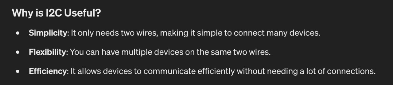
Understanding I2C
Before getting started I had to understand the protocol a bit deeper. I started out with Neil's lecture material, Fablab BCN's local lecture material, consulted ChatGPT and read the Arduino article. Summarized it's a two-wire communication protocol that allows communication between several devices through a parent device. While all devices need to share ground the communication is done with SDA (Serial Data Line) sending and receiving data and SCL (Serial Clock Line) timing the communication at the same speed for all devices.
Writing this documentation I can only share a smile about ChatGPT's summary, because I probably used 50 cables, it took me several days to figure out my issues when connecting several devices and it did not feel very efficient.
Testing the magnet connection
My priority was to test if the SDA and SCL line was transmitting data via magnets. Since I had not gotten into understanding the code yet I used Riichiro's example to test with my SAMD21 board from Input devices and the Barduino.
Blinking the LED on the SAMD11 board works through all the magnet connection, which means data is transferred. Next step was to test with several devices and figure out the code.
Facing Hardware Issues
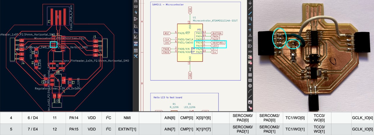
When researching I2C on the SAMD11 datasheet I realized I had mixed up the SDA and SCL pins with the D- and D+ pins. Since I had put the LED on one of the pins I had to create a "Frankenstein" to test my board with the I2C and create a network.
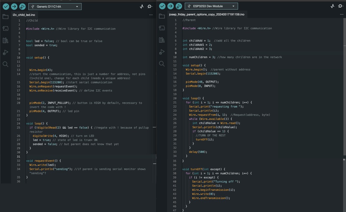
Understanding the Code necessary
Thanks
Please find the code files here: parent_code, child_code
Child-Parent Connection
Once I ran the code on my first child board it seemed to work but once I connected the second child it stopped receiving data.
Troubleshooting Children-Parent Connection
After I tried all children individually and they were all receiving and sending data over the SCL and SDA line directly I had several options to debug:
- it's a code problem
- it's a hardware problem
In order to rule out a problem with the code I connected two "Barduino" children to a "Barduino" parent and it worked. Thus it's NOT a code problem.
Since the Barduino is a commercially produced board I tried Max's board to test whether the issue was the development board, but that worked as well. Both data was received and sent.
So the research began again and I realized I did not have a pullup resistor on the SDA nor the SCL line, as described in our Fablab BCN's local lecture material. So I added a 5K Ohm resistor on the bread board to one of my boards and child A is communicating to child B. Yeah!
Lessons Learned
- triple check the pin-out
- borrow all the Barduinos you can get to test
- 5k Ohm resistor!!