11 Input Devices
This week's assignment is to probe an input device(s)'s analog levels and digital signals and measure something: add a sensor to a microcontroller board that you have designed and read it.
Group assignment: Input Devices
The documentation for our group assignment from the Barcelona node can be found here.
Lessons Learned
- get a quick introduction to the oscilloscope if you are a first-time user
Capacitive Touch for my Stacking Lamp
ATTiny1614 attempt
This week I really wanted to try out capacitive touch as a "cool" on/off switch for my final project, a lamp. Initially I wanted to use my board from Electronic Design Week with an ATTiny1614 microcontroller, because it powers the Neopixel strip at 5V.
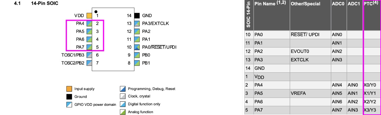
Turns out the ATTiny1614 has the capability of Peripheral Touch Controller (PTC) on PO4, PO5, PO6, PO7, which is explained in section 32 of the datasheet. But when I asked to our instructors they were not sure if it was possible to program it using Arduino IDE.
On their recommendation I swapped to designing a new board, which we were sure that it would work. Finally
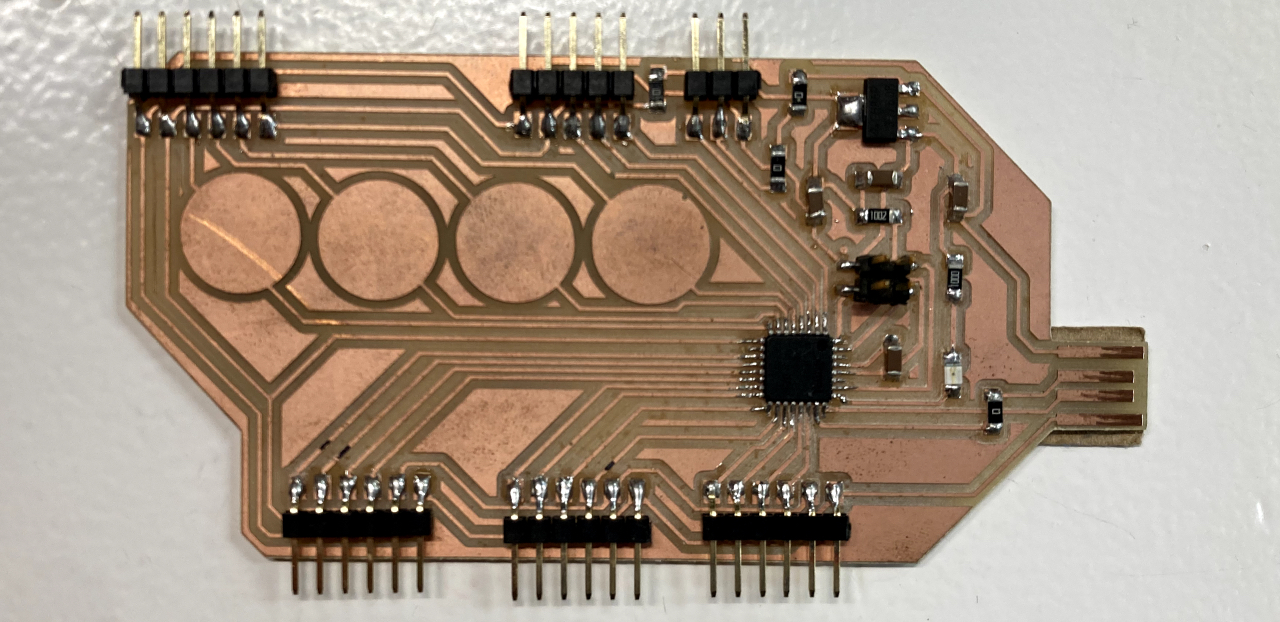
A SAMD21 board
So I swapped to a SAMD21, which initially was a big jump for me being a complete electronics newbie, but thanks to
Understanding Capacitive Touch
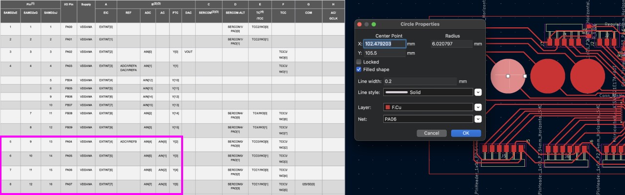
Since I had already checked the PTC capacity for ATTiny1614 I knew what I was looking for in the datasheet. SAMD21 has the capability of self-capacitive mode, which only requires a Y-line, on pins PO4, PO5, PO6, PO7.
As stated in the datasheet "the external capacitive touch sensor is typically formed on a PCB", which means I had to create a circle and declare it as a Filled Shape and choose the Net
I wanted to connect, which means the respective pin.
Power Supply
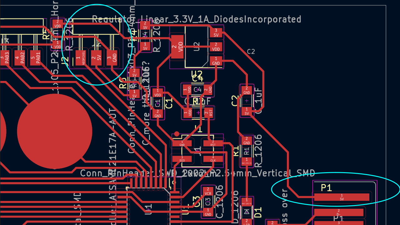
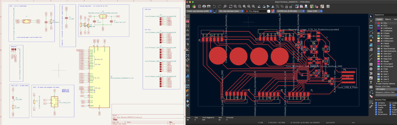
The SAMD21 comes with different power supplies: VDDCORE for the internal power supply of the microcontroller and VDD to supply the board. Since I was still following my initial plan of powering the Neopixel strip, I added a direct lane from the usb connection to a 3-pin header.
Data
A lesson shared by
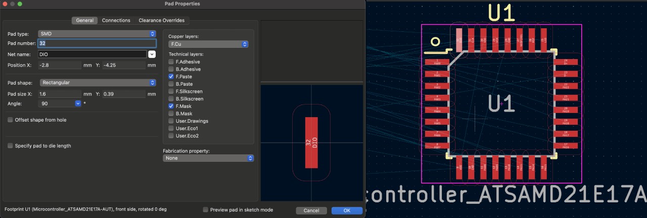
Another hint from everyone in the lab that had used the SAMD21 was to increase the size of the footprints, which can be edited with Control + E
in KiCad.
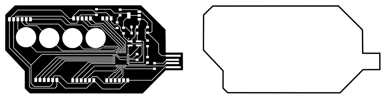
Once I had finished the work in KiCad, I followed the same procedure as described in electronic production week:
- export selected as SVG
- edit in Inkscape
- create rlm file with modsproject.org
- mill the board
- solder components
- burn bootloader with Quentorres
- try blink program - works! :)
Programming Capacitive Touch
Once I had the board ready I started to understand the code from Quentin Bolsee's flexible capacitive sensor example and installed the Adafruit Freetouch Library.
Initially I could not really make sense of the examples code, thus I used this Adafruit blogpost and Andrea Rubio's documentation to understand the several necessary steps better:
- include the library
- declare the capacitive touch pins using
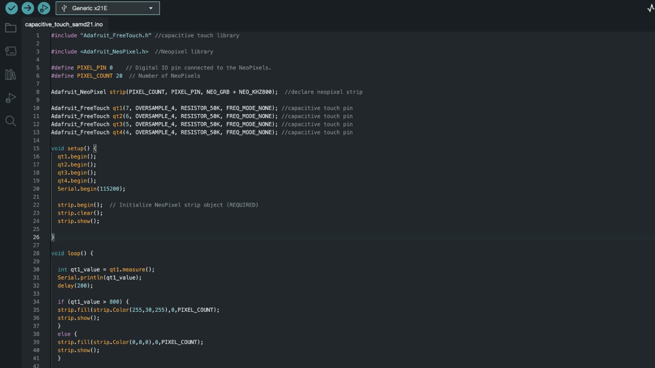
Adafruit_FreeTouch qt1(7, OVERSAMPLE_4, RESISTOR_50K, FREQ_MODE_NONE); - void setup: start Serial communication to see the sensor reading
- void setup: start the sensor reading with
qt1.begin(); - void loop: start the actual sensor measuring with
int qt1_value = qt1.measure(); Serial.println(qt1_value); delay(200); - void define what action to trigger at a certain sensor reading with
if (qt1_value > 800) {} - else {}
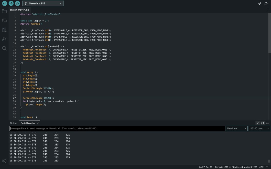
I played with the sensor's variables of oversample, series resistor and frequency mode a little bit, since my capacitive touch pins are very close to each other the readings started in the 200-400s.
Eventually my goal was to use the capacitive touch as a button for my lamp, thus it should output the neopixel strip. I started gradually with blinking the LED which worked fine - keeping a little flickering still.
Neopixel one pin/breakout button
I realized that just defining one touchpin - calmed the flickering on the neopixel strip as well. The little breakout board changed the sensor reading a little bit. On one pin the initial reading was in the 500s so I had to adapt the code, on another pin instead the reading dropped to 100s. So I had to keep that in mind!
Neopixel four pins
Eventually I used all four pins to light the neopixel strip in different colours using the following code. Please find the .txt file here.
Lessons Learned
- check the sensor readings with the breakout board
- don't forget to start the sensor reading in the void setup
- keep the code simple - it's a nice to have to have a single printed line with all readings