08 Electronics Design
This week's assignment is to use the test equipment in your lab to observe the operation of a microcontroller circuit board and use an EDA tool to design a development board to interact and communicate with an embedded microcontroller.
Group assignment: Electronics Design
The documentation for our group assignment from the Barcelona node can be found here.
Lessons Learned
- keep in mind the ampere range of your board and choose the right range on the multimeter
- "easy to use interface" still does not seem that intuitive on first use of the oscilloscope
A development board to power a neopixel strip
1. Concept
For my final project I want to create a lamp, so this week I wanted to experiment with the Neopixel Strip, which is powered at 5V. I asked to our local instructors and they recommended the ATTiny since it already works at 5V. Being a bloody beginner on electronics easy sounded perfect.
I studied the Adrianino as a reference and quickly saw the hello.serial.UPDI.board. To understand the necessity of it I went a tiny bit deeper into understanding, why AVR architecture micro-controllers cannot directly communicate with serial.
Starting off from the lecture material,
to Wikipedia, the Arduino help, to eventually asking ChatGPT
to explain the topic for kids, middle schoolers and high schoolers. That was a great tip on the Welcome Week! Eventually the explanation of
Obviously the topic is vast and I just scratched the surface, but for an hands-on-approach it was fine to understand that different microcontrollers speak different languages, some can learn to communicate in Serial like the SAMDies others like the ATTinys need a "translator" the hello.serial.UPDI board.
2. Design

To draw my development board i used KiCad. Some useful shortcuts were E for editing elements, A
to add new elements, Rto rotate, U to select one full trace and D to move elements on the PCB together with the traces. The file can be found here.
It's important to change the right clearance (0.4), track width (0.3), Via Hole (1.2), Via Size (0.8) under Track: Use Net Classes/Net Classes before!
you start drawing traces on the PCB.
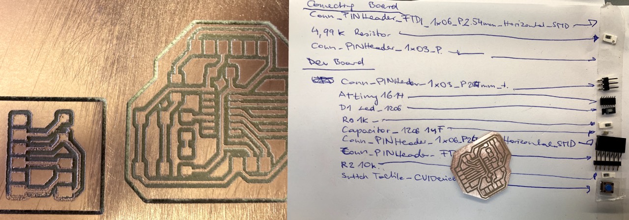
I decided to do a rather small board with the following electronic components:
- Microcontroller: ATTiny 1614
- UPDI Connector: to the hello.serial.UPDI board (to program the board using the Quentorres) in form of a 3-position-pinheader (CONN HEADER SMD R/A 36POS 2.54MM)
- Hello LED (SM0805UGC) and 1k Ohm Resistor (Yageo RC0603FR-071KL): 1206 indicates only the size not the value of the resistor (to test the board)
- A 6-pinout connection (CONN HEADER SMD R/A 36POS 2.54MM) for the Neopixel strip
- an extra FTDI connection to directly connect the Quentorres or a Bluetooth module in form of a pinheader (CONN HEADER SMD R/A 36POS 2.54MM)
- A 1 uf capacitor (Kemet C1210X105K5RAC3316): because at that moment I thought each board needs one to keep a constant powersupply, instead this is only necessary if the board contains components with different voltage input
- A tactile switch (Schurter 270-7935) and 10k Ohm resistor (YAGEO RC1206FR-0710KL): to have an additional input for the neopixel strip (turned out to be completely unnecessary)

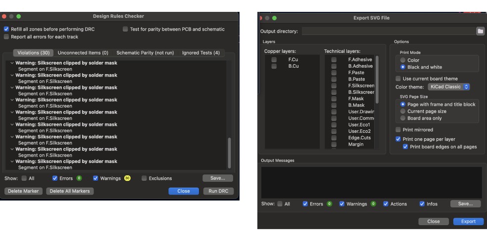
After I drew the traces I used Inspect/Design Rules Checker to check for errors and exported the PCB as an .SVG file to create the .PNG files.
3. Prepare

To prepare the .png files I used Inkscape. The most important was to create different layers for Traces, Footprints and the Outline.
So it get's easier to change the footprint's Fill to white and traces' Stroke Paint to white. I created a custom outline in Inkskape with a stroke with of 0.8 to
match the 1/32 endmill. On exporting the png files keep in mind to select the same size for traces and outlines and change the DPI to 1000.
The second step was to prepare the .rml files with modsproject.org for the Roland SRM 20, our lab's PCB milling machine.
To select the right presets I opened programs/open program/Roland/SRM 20 mill/mill 2D PCB and prepared the files in the following order: traces, holes and outline.
I uploaded the .png file and first did not check the DPI settings in the upload section. For this reason I had to redo the files again, since instead of 1000 DPI it was orginally set to 999,967.
The next step was to choose the drill mills: traces (1/64"), holes and outlines (1/32"). Once selected the mill 2D settings will calculate the right settings
automatically, with only minor adaptations: For traces an offset number of 4 is sufficient, keeping an offset of 0 will cut away the copper all the way, which would take much longer.
To check for offset errors I used the View mode.
On our lab's machines the recommendation is to set the max depth to 1.75 for holes and outlines, which differs from the calculation, but preserves the base plate.
If you hit calculate at this point the file will be downloaded - it's better though to wait until all settings are done.
Continuing with the machine's settings of the Roland SRM 20:
speed: traces (3mm/s); cut (0.5 mm/s)origin: will be set on the machine (0/0/0)jog height: 5home: x/y doesn't matter, z default of 60 mm is fine
Finally choose the save file option and hit calculate to download the .rlm files and copy them to the IAAC cloud to be able to access them from the laptop
connected to the machine.
4. Fabricate

The milling of my PCB turned out a little bit hairy in the beginning but sanding the top did the trick. I just had scratch out a few scraps of copper that got brushed on again. After I collected all the components I started soldering.
The soldering process is quite ease with these few components following these steps:
- I start with the microcontroller: add a little solder to one pin fix the mc in place and fix the other pins
- solder the components from "flat" (e.g. resistor) to bigger components (e.g. switch)
- test the connections using a multimeter
The only issue i encountered was, that I did not know in which direction to put the LED, but lesson learned that the yellow LEDs we use do not have an indicating arrow on the back - so I checked the datasheet on the direction of anode and cathode.
5. Testing & Debugging
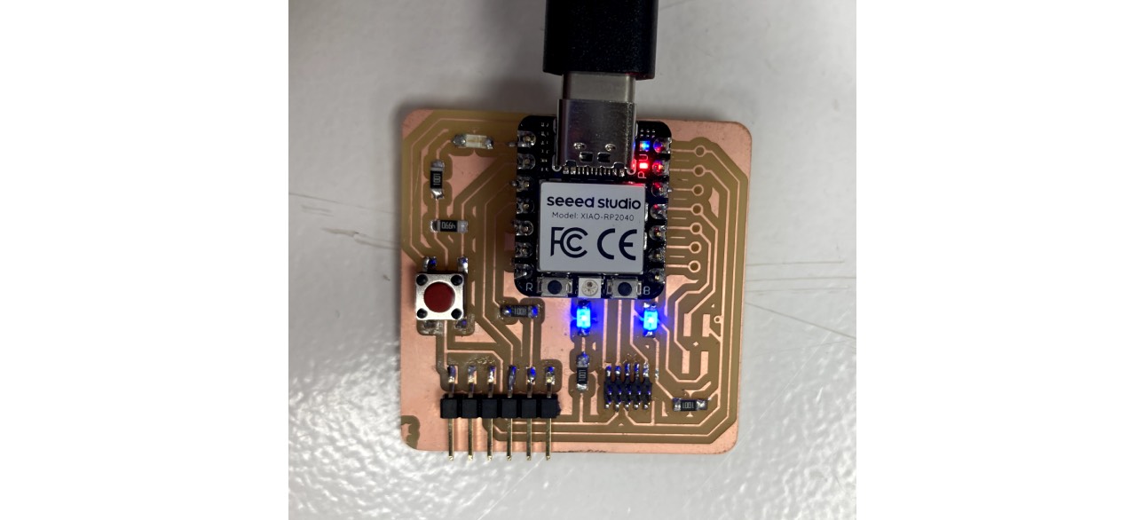
Initially I had to set up the Quentorres to use as a programmer following the 3-Step-instructions on the documentation. Lesson learned that once it's working two LEDs will light up.

Second step was to download the megatiny Core library following these steps:
- insert
http://drazzy.com/package_drazzy.com_index.jsonin Settings/Preferences/Additional Boards Manager URLs - download the library under
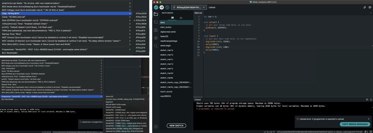
Tools/Board/Board Manager - select the right ATTiny microcontroller: 1614
- choose the programmer
SerialUPDI ... (CH340 and maybe some others)

Once I uploaded the "Blink" programme i received the following error A programmer is required to upload..
Once I uploaded the Blink programme on Windows I kept on receiving an UART initialisation failed error.
Thanks
- remove the microprocessor with the heat gun and solder in the right! direction (the dot needs to be in the upper left corner): FAILED, but probably burned the LED
- try with a different FTDI to UPDI connecting board to the Quentorres: FAILED
- directly try the FTDI connection: FAILED
- remove the unnecessary capacitor (only necessary if a component needs less than 5V, which would also call for a Voltage regulator): FAILED
- check the soldering with the multimeter, they seemed fine
- try with a commercial FTDI programmer: FAILED
- check the pinout again if the UPDI pin was correctly wired - it was not - solder a bridge for the connection: FAILED
- check the direction of the LED, resolder in the other direction: FAILED
- recheck the solder connection: LED was not lighting up: FAILED
- solder a new LED: FAILED
- swap the PIN from 5 to 3 (we really don't know the reason, why the pinout does not match): SUCCESS on Linux and Windows
Once we made it work on Linux and Windows - I tried to make it work on MAC as well adapting the recommended steps for Linux to MAC:
- check on terminal if python or pip was istalled: no
- download python using homebrew
brew install python - check for the used version
- @Dani created an environment to install PIP
- export the file in Arduino IDE
Sketch/Export Compiled Binary - check where this file is located
Sketch/Show Sketch Folder - check which port is used
Tools/Port - run the following code on terminal:
~/test_python/bin/pymcuprog write -t uart -u /dev/cu.usbmodem4471FA153 -d attiny1614 -f /Users/magdalenamilly/Documents/Arduino/blink/build/megaTinyCore.megaavr.atxy4/blink.ino.hex --erase --verify
6. Program the Neopixel

Eventually ATTiny is not programmable with MAC and the Quentorres - so I will need to swap to another SAMD programmer, which I describe in the Output devices documentation, because it's just not feasible to only programm on the lab's computers.
Lessons Learned
- sanding your board after milling improves a cut, that is not perfectly smooth
- the ATTiny Pinout is not userfriendly at all - seriously error-prone (PA07 = 3 = 5)?
- Debugging is a teamsport