09 Output Devices
This week's assignment is to measure the power consumption of an output device and add an output device to a microcontroller board you've designed and program it to do something.
Group assignment: Output Devices
The documentation for our group assignment from the Barcelona node can be found here.
Lessons Learned
- it's a beauty to navigate data sheets, hard to find fast what you really need for polulu devices
- we could not really explain the difference in sensitivity, which would need further in-depth investigation
A development board to power a neopixel strip 2.0
This week I continued my quest to create a board that could control a neopixel strip for my final project and which I was able to program with MAC.
"Frankie"
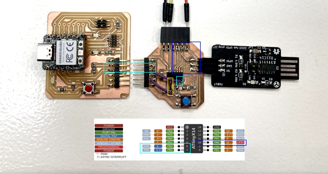
Since I wanted to understand my mistakes I made on the board during Electronics Design Week I continued using it and created a "Frankenstein".
In general I had misread the pinout during the design of this PCB and ignored to double-check when doing the schematics. I had connected the UPDI to the wrong pin 9 instead of 10. So I had to scratch the connection and connect to pin 10. It was easier to do so using one of the pinheader pins since there was more space for the wire. Second mistake was that I had simply not created any connection to the button. I solved that with a wire from pin 04 to the resistor. And third but not least I had RX connected to RX and TX to TX for the serial connection, instead of RX-TX and TX-RX.
A SAMD programmer to program ATTiny from MAC
In the past week I encountered that I could not program the ATTiny with MAC, but eventually I could not program it using MAC and the Quentorres. Thus I used the fab UPDI programmer instead.
Thanks
- switched to Windows again
- used another SAMD programmer instead of the Quentorres
- checked my soldering with the multimeter
- resoldered some of the connections
- took off the LED
- changed the voltage regulator!! (which was simply the wrong component in the right box) and it worked
After burning the boatloader I could start testing my board on MAC.
Connect the Neopixel Strip
As with the blink program for LED I started with the strandtest.ino to simply try if the neopixel strip would lite up. Which it did not... I received an error that The clock was not set at the right speed. after changing the clock to 16 Mhz which the Neopixelstrip requires nothing changed.
I reset the board and checked the connections in Arduino but no success. After I googled and found that on the arduino forum some people had the same issue and used a different library instead:
tinyNeopixel part of the ATTinyCore library. So I installed the library included it
in my code and ran another strandtest without any success.
Eventually I asked to
Program the Neopixel Strip
Unfortunately at the time I wanted to complete this assignment this board had gotten some issues and was not working fine anymore. Thus I used the SAMD21 board I made for my input devices assignment and created one code for both assignments. Please find the complete code file here.
Once I had the board ready I started to understand the neopixel from several examples from our lab's Adventronics Challenge and the Adafruit Neopixel Uberguide.
Thanks also to
Arduino Code explained
          #include "Adafruit_NeoPixel.h"  //Neopixel library
          #define PIXEL_PIN 0    // Digital IO pin connected to the NeoPixels.
          #define PIXEL_COUNT 20  // Number of NeoPixels
          Adafruit_NeoPixel strip(PIXEL_COUNT, PIXEL_PIN, NEO_GRB + NEO_KHZ800);
          //declare neopixel strip

          #include "Adafruit_FreeTouch.h" //capacitive touch library
          Adafruit_FreeTouch qt1(7, OVERSAMPLE_4, RESISTOR_50K, FREQ_MODE_NONE);
          //capacitive touch pin
The first step was to include the Adafruit neopixel library. The next step is to declare the neopixel object, answering two questions:
- Which pin is connected to the neopixel strip?:
define PIXEL_PIN - How many pixels does the strip have?:
define PIXEL_COUNT
These two arguments together with the colour range/bitstream the neopixel strip uses - in this case GRB (GREEN - RED - BLUE), which has caused some confusion on the way, because I am used to the RGB standard and "NEO_KHZ800" stands for the bitstream the object uses.
These four pieces of information together declare the strip: Adafruit_NeoPixel strip(PIXEL_COUNT, PIXEL_PIN, NEO_GRB + NEO_KHZ800).
After the initial definitions the programming can advance to the void setup:
        void setup() {
          qt1.begin();
          Serial.begin(115200);

          strip.begin();  // Initialize NeoPixel strip object (REQUIRED)
          strip.setBrightness(64);
          strip.clear();
          strip.show();

        }
In the void setup it is a MUST to "start" the neopixel object, without this line of code nothing is going to happen: strip.begin(). Since the neopixel are very bright,
I used strip.setBrightness(64) to lower the light emitted by each neopixel, for the lamp though strip.clear() and very importantly also show the action you want the strip to do with strip.show()
Since I wanted to use a simple show of colour, when the button (in this case the capacitive touch button) is pressed, I defined the void loop as follows.
          void loop() {

            int qt1_value = qt1.measure();
            Serial.println(qt1_value);
            delay(200);

            if (qt1_value > 800) {
            strip.fill(strip.Color(255,30,255),0,PIXEL_COUNT);
            strip.show();
            }
            else {
            strip.fill(strip.Color(0,0,0),0,PIXEL_COUNT);
            strip.show();
            }
          }
I used an IF statement to define the ON and OFF state of the strip. With the function strip.fill I set:
- a specific colour to the strip using the GRB standard:
strip.Color(255,30,255) - defined which pixel in the strip lights up first = 0 (the first one), keep the direction of the strip in mind here
- defined which pixels light up: PIXEL COUNT, since I wanted all to be the same colour
Very importantly again show your defined action with strip.show().
for the ELSE statement I initially used strip.clear() which gave me zero or a result showing different colours, so I defined
the colour as black, which worked fine.
In general one particular lesson learned was to watch the power supply for the strip, because if the board was plugged loosely the colours would differ or the strip would not only light up some pixels or flicker.
In action
Lessons Learned
- if you change the clock of a microcontroller you need to burn the bootloader again
- don't forget to use strip.show to display the action you would like the neopixel strip to do
- watch the powersupply for the neopixel strip/board else the strip starts flickering or playing different colours