Week 11 - Input devices
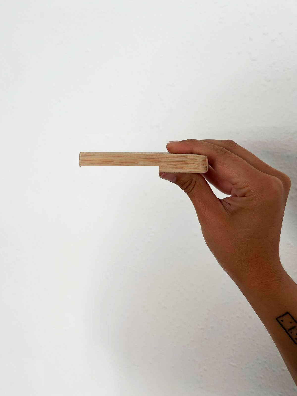
Capacitive touch readings through wood
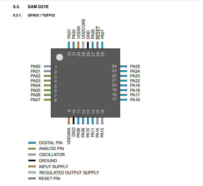
Using SAMD21 microcontroller as new development board
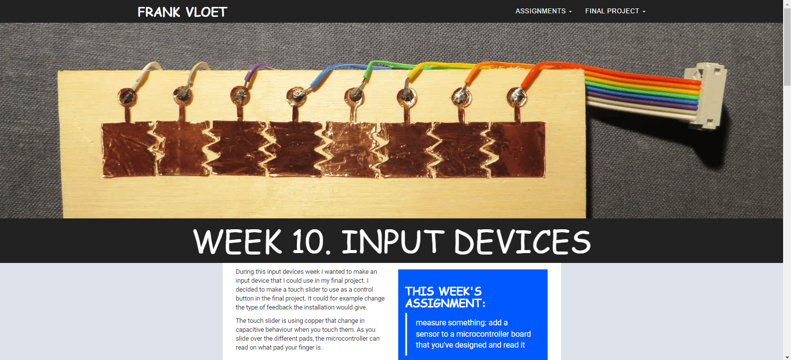
Since electronics design, I wanted to focus with my final project board regarding capacitive touch. So I continued working with my last board to try to understand how much sensitivity I can obtain by having a wood cover.
Conclusions: the capacitive works below the wood but the values are still very random because there is no direct touch with the copper, so the major work will be experimenting with code to determine the best reading. Also I want to integrate more capacitive touch pads/functions so I will upgrade to SAMD21 to have move memory and pins.
References
Having that in mind, I used as reference 2 previous Fablab projects to help me understand how to develop what would be my next board. Both projects and my instructor Josep were very helpful and I was able to understand mainly the amount of components to start designing my pcb.
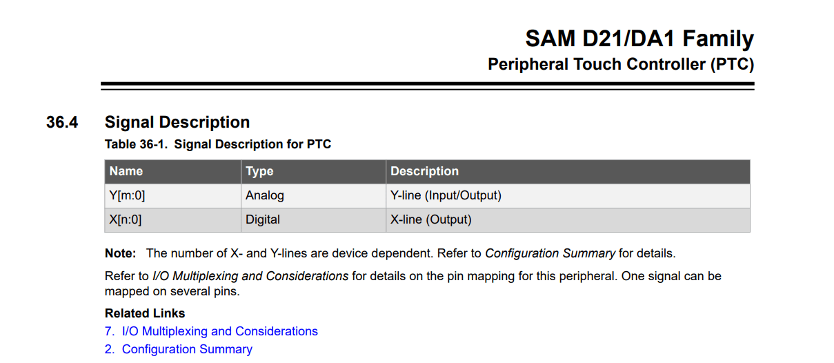
Understanding datasheet
These were some of the steps that I started with regarding electronics:
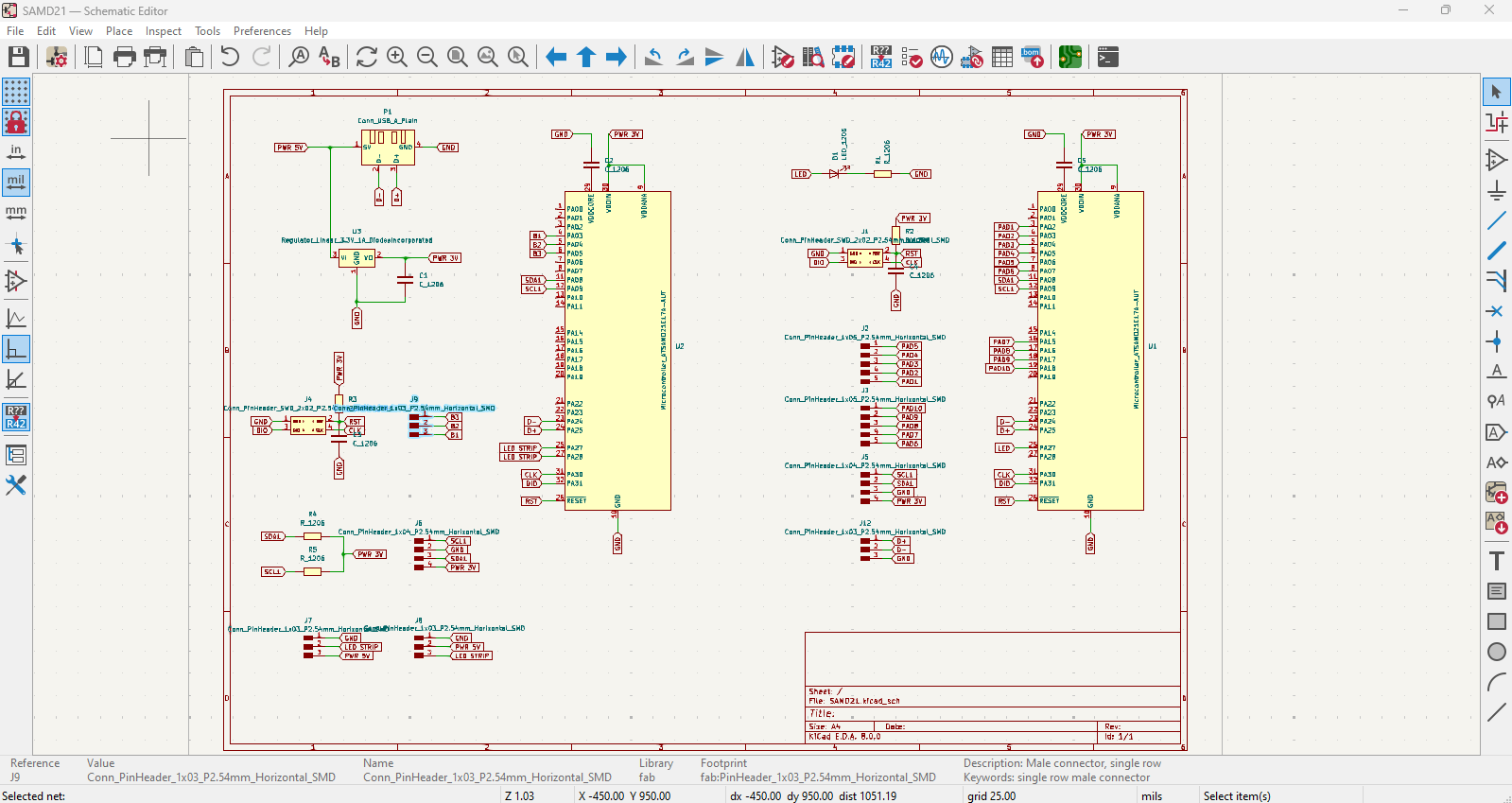
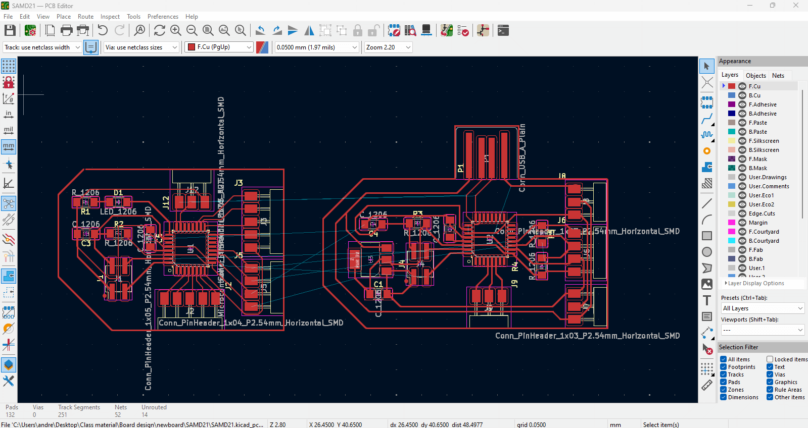
KiCAD pcb design
Components and Connections
The schematic is divided into several sections, each representing different parts of the circuit:
***Before tracing: Set as default***
Since It's important to change the tracing values for a correct offset between the design paths.
Go to: File / Board Setup / Net Classes
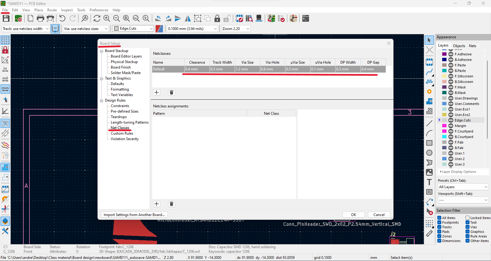
Traces
1. Arrange and connect components according to schematic design.
2. Before exporting the board check that everything is correct through the "Design Rules checker":
3. Some of the Errors & Warnings are because I haven't drawn the outline of the board and not attached traces for the touch pads.
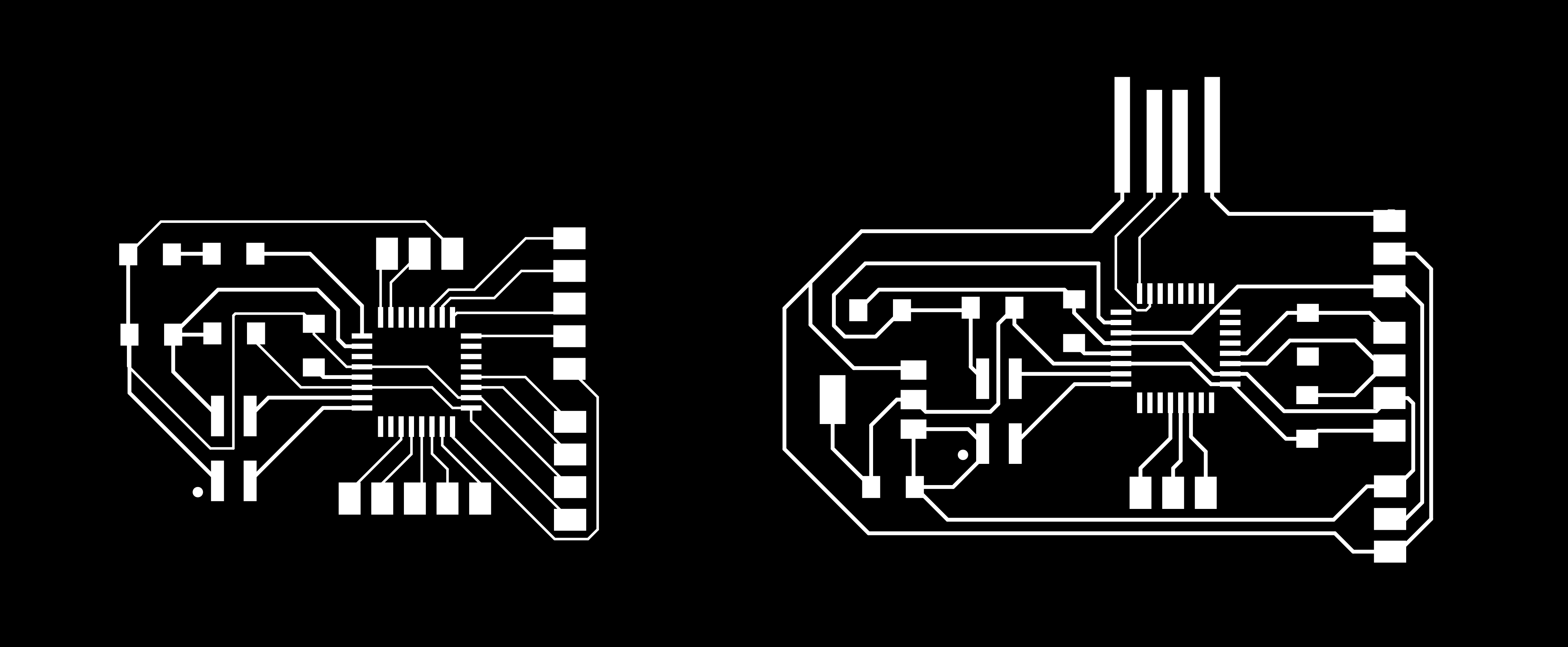
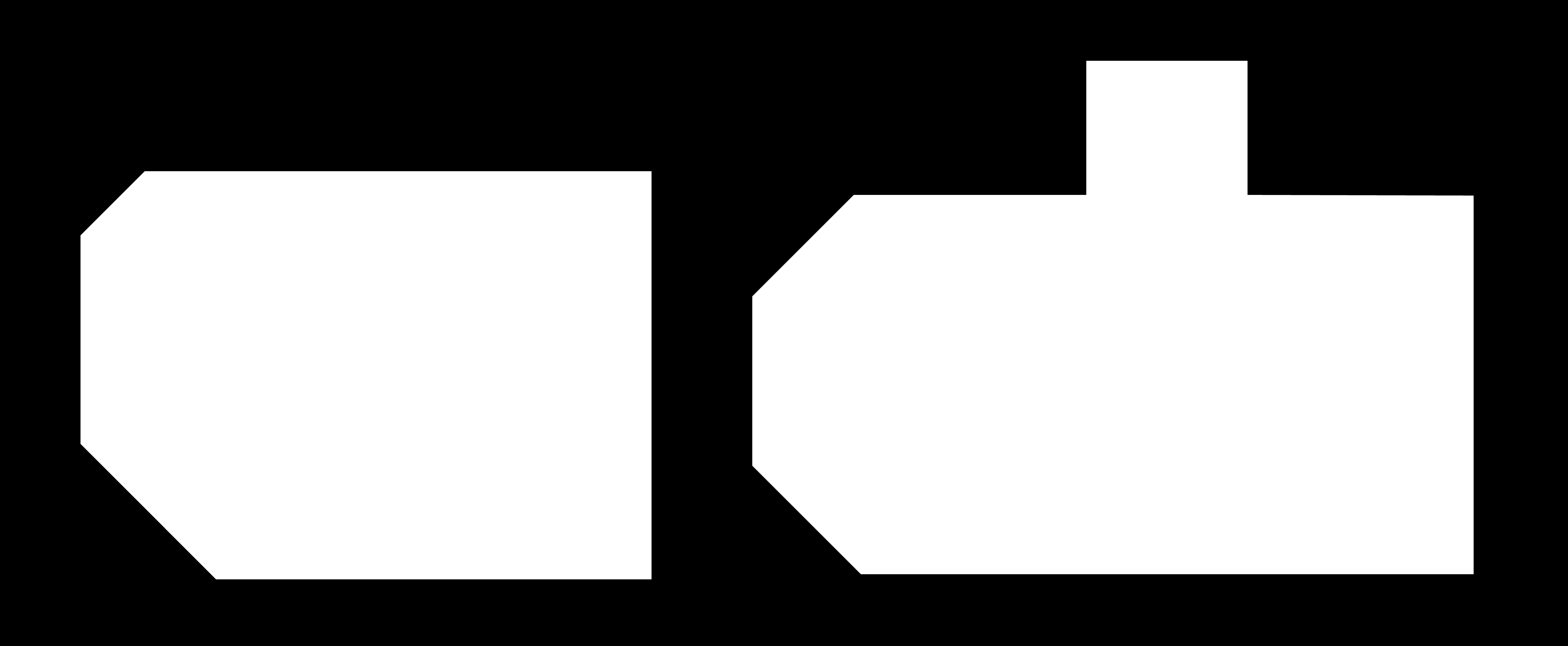
4. Export board to SVG file.
Customize board
1. Open SVG file using Adobe Illustrator to invert colors for mods.
2. Black: removes // White: keeps
3. Export "Traces" and "Outline" seperatly as PNG file with 1000 dpi quality each.
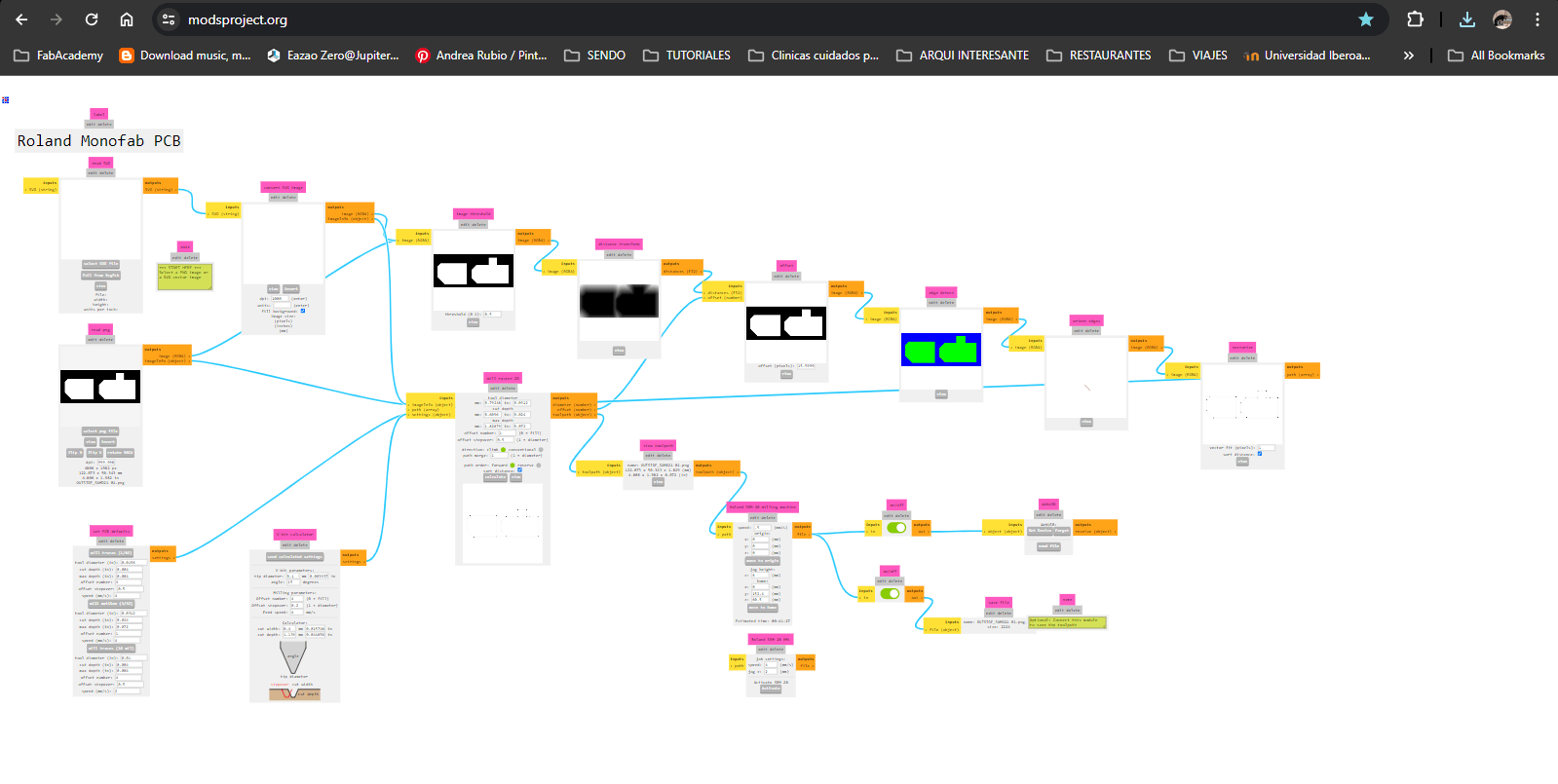
Modsproject parameters
1. Open modsproject.org / right click anywhere / select programms / look for SRM-20 milling / select "mill 2D PCB".
2. Upload the Tracing file that was customized.
3. Select from the box below the option mil traces (1/64), we begin with the smallest bit to trace our design.
4. On the "Roland SRM-20 milling machine" box we change the following settings according to the 1/64 bit:
- - Speed: 3 mm/s
- - Origin: x,y,z = 0
- - Jog height: 5 mm (elevation of the bit each time it moves)
- - Home (z): keet high just for safety of the bit
5. On the "mill raster 2D" box, change the offset number to 4 as a default and safety tracing. This number could vary from 3 or 4.
6. Press "Calculate" to generate a preview and automatic download of the machine's tracing path. See preview (blue lines).
7. Upload first the Outline png file.
8. Select from the box below the option mil outline (1/32), we continue with the bigger bit to do the final cut of the board.
9. On the "Roland SRM-20 milling machine" box we change the following settings according to the 1/32 bit:
10. Press "Calculate" to generate the preview.
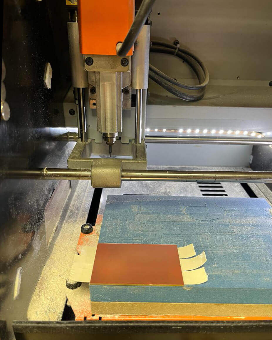
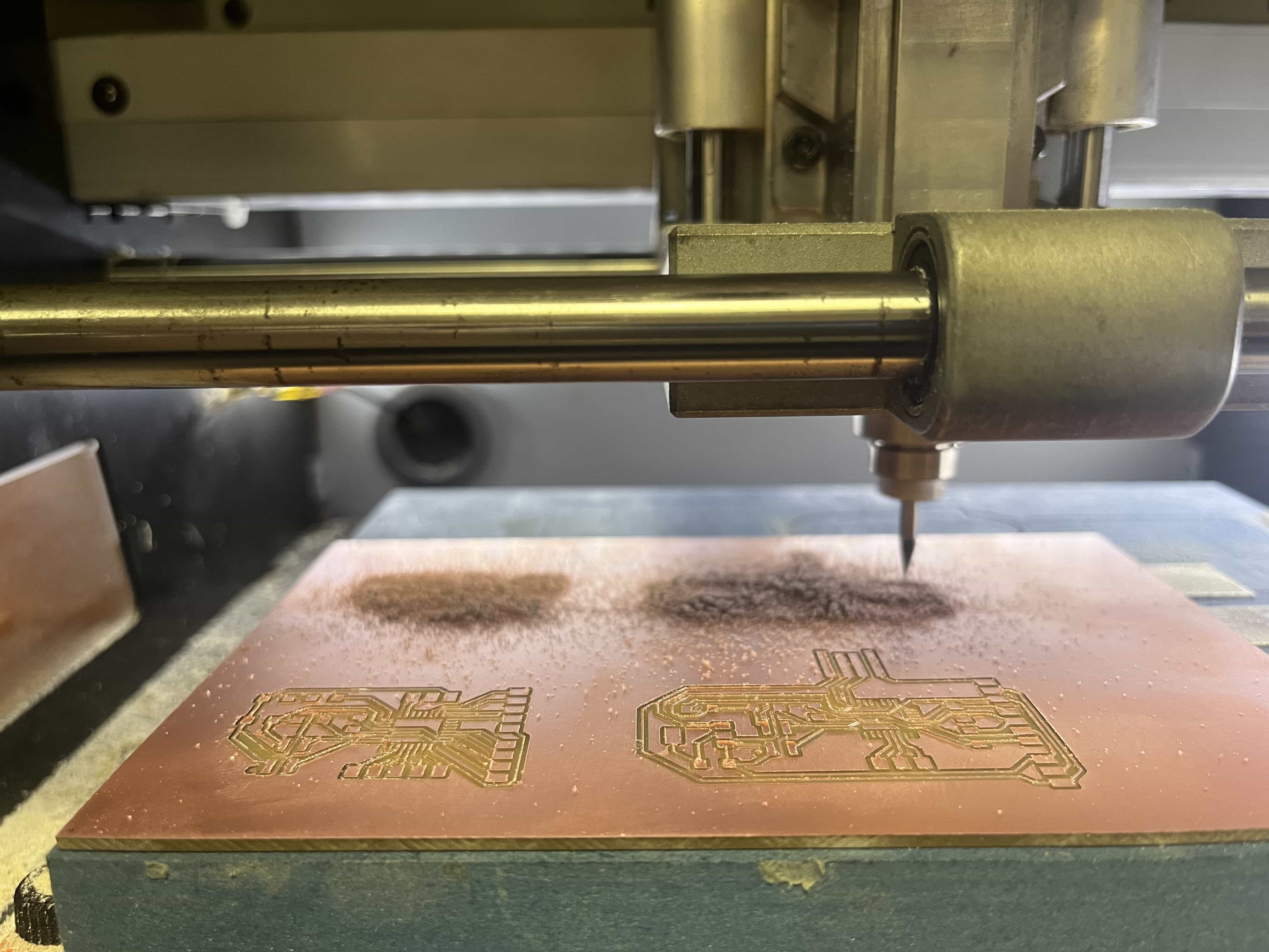
Roland SRM-20 milling machine
Setting PBC board & milling bits
1. [First image - left] Grab PCB and apply double side tape on the non-copper face. Leave extra space for peeling the side and not affect the base leveling.
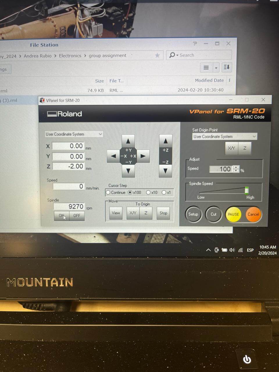
2. [Second image - left] Open software / Set XY and Z using up/down/right/left keys until it's leveled.
3. [Third image - right] Change bit to 1/64 since we are starting with the tracing file / Set Z carefully dropping the bit so it touches the board.
***IMPORTANT: Make a spindle test to ensure the bit is leveled and avoid missed cuts.
4. On the software, select "Cut" and add the tracing file / press "Output" to start.
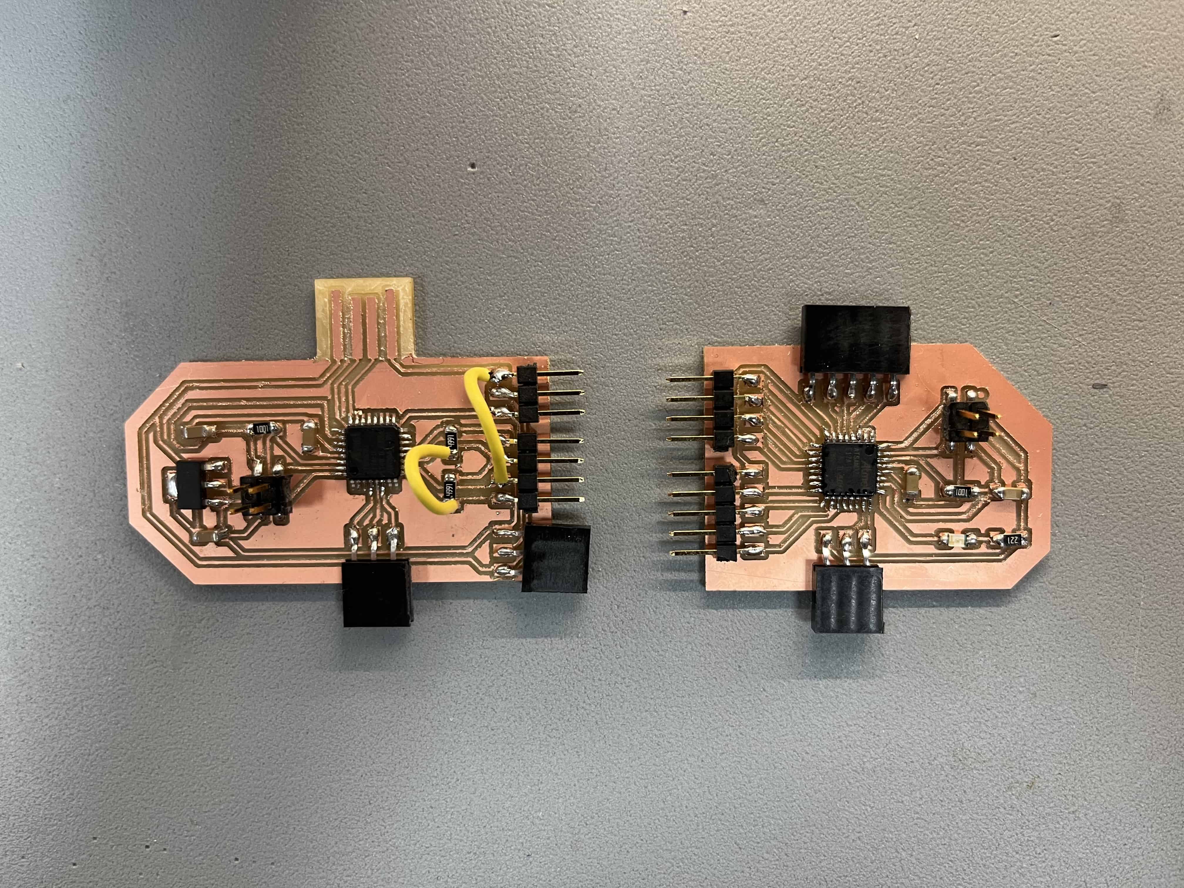
Soldering components
Common Issues and Solutions
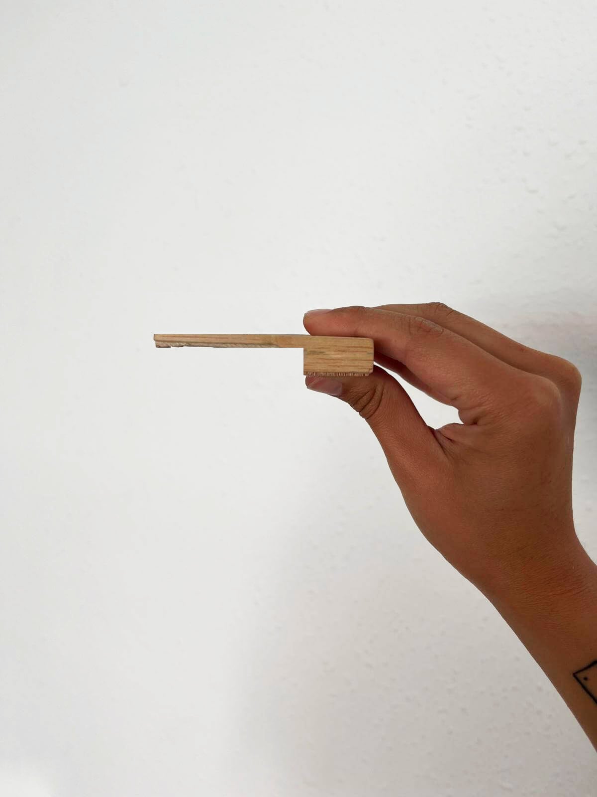
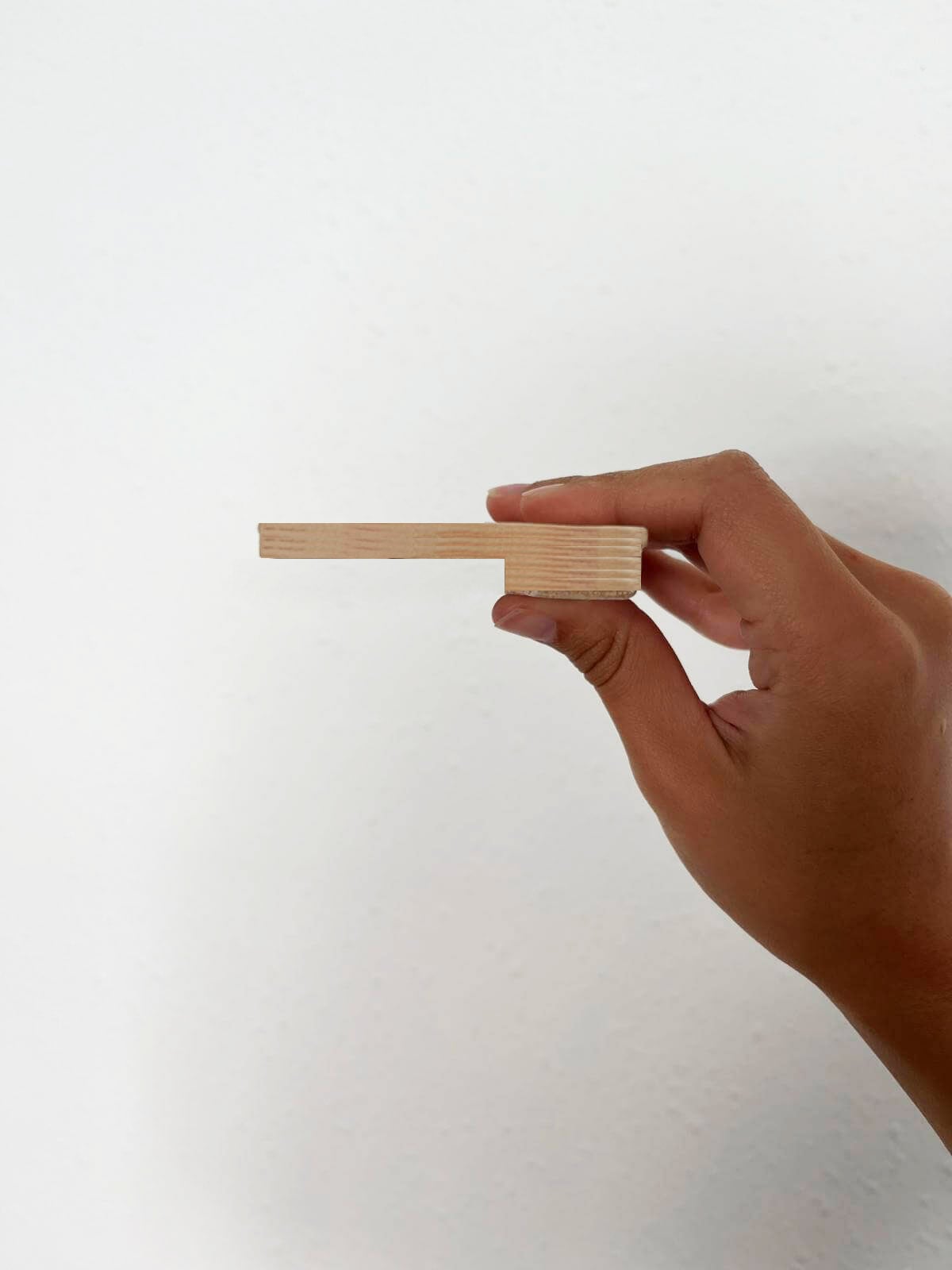
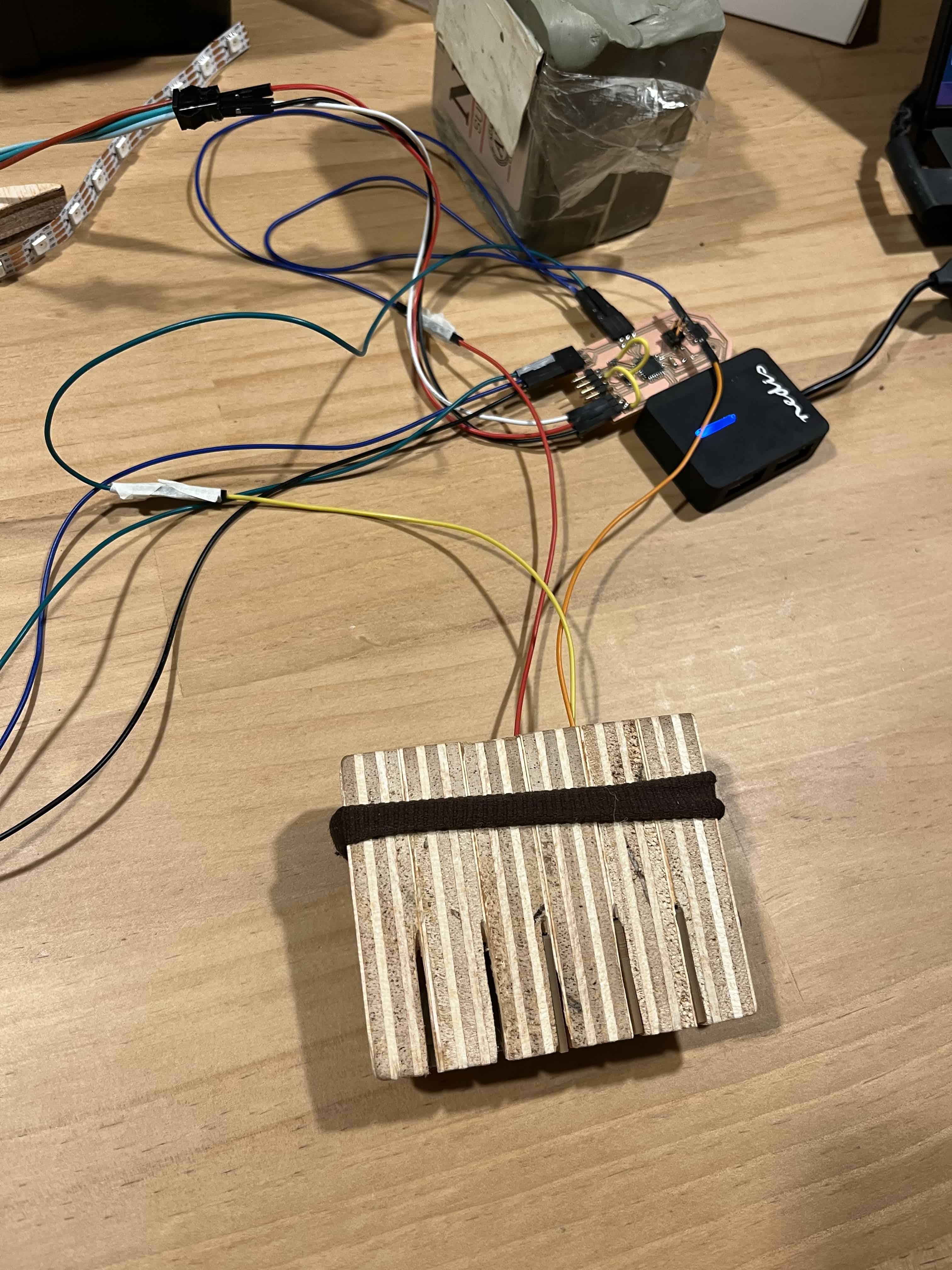
Spiral development - Wood slots
I worked with the same scraped wood prototype which I later trimmed using a small dremel that I found at the carpentry. I made thin slots in between each lamella of wood in order to fit the copper pads and have a better visualization of the tables aesthetics and functionality.
From left to right you will see the thickness differences from 2.5mm - 5mm - 7.5mm. And until the very end the final outcome and appearence.

Arduino IDE: Capacitive touch + Neopixel lighting programming
Libraries and Definitions
The code uses Adafruit_NeoPixel and Adafruit_FreeTouch libraries. Constants are defined for pin connections, number of LEDs and colors, velocity settings, and touch thresholds.
          #include <Adafruit_NeoPixel.h>
          #include "Adafruit_FreeTouch.h"

          #define PIN 28
          #define NUMPIXELS 18
          #define NUMCOLORS 6

          #define COLOR_CHANGE_VELOCITY 0.005
          #define SMOOTHING_VELOCITY 0.003
          #define SLIDER_VELOCITY 0.005

          #define QT1_THERSHOLD 650
          #define QT2_THERSHOLD 700
          #define QT3_THERSHOLD 550
Initialization
The NeoPixel strip and touch sensors are initialized. Variables for touch sensor states are declared.
          Adafruit_NeoPixel pixels(NUMPIXELS, PIN, NEO_GRB + NEO_KHZ800);
          Adafruit_FreeTouch qt1(3, OVERSAMPLE_4, RESISTOR_50K, FREQ_MODE_NONE);
          Adafruit_FreeTouch qt2(4, OVERSAMPLE_4, RESISTOR_50K, FREQ_MODE_NONE);
          Adafruit_FreeTouch qt3(5, OVERSAMPLE_4, RESISTOR_50K, FREQ_MODE_NONE);
Color and Pixel Data
Arrays and variables manage LED colors and states. Colors holds RGB values for six colors. TargetColor and CurrentColor store RGB values of the target and current colors. CurrentColorIndex tracks the color index. sliderValue adjusts the number of active pixels.
          float Pixels[NUMPIXELS];
          float PixelsTarget[NUMPIXELS];
          int Colors[NUMCOLORS][3] = {
            { 255, 200, 90 },  // Orange
            { 255, 180, 50 },  // Yellow
            { 255, 50, 10 },   // Red
            { 30, 255, 30 },   // Green
            { 30, 30, 255 },   // Blue
            { 255, 255, 255 }  // White
          };
          float TargetColor[3];
          float CurrentColor[3];
          int CurrentColorIndex;
          float sliderValue;
Setup Function
The setup function initializes the target color, touch sensors, and NeoPixel strip. The pixels are cleared and turned off.
          void setup() {
            SetTargetColor(CurrentColorIndex);
            CurrentColor[0] = TargetColor[0];
            CurrentColor[1] = TargetColor[1];
            CurrentColor[2] = TargetColor[2];
            qt1.begin();
            qt2.begin();
            qt3.begin();
            pixels.begin();
            pixels.clear();
            pixels.setPixelColor(0, pixels.Color(0, 0, 0));
            pixels.show();
          }
Main Loop
The loop function updates the LEDs based on touch input. It changes the color index if the third touch sensor is clicked, adjusts the slider value, and updates the active pixels. The current color transitions smoothly to the target color, and pixel states are recalculated.
          void loop() {
            pixels.clear();
            bool touchQ1 = qt1.measure() > QT1_THERSHOLD;
            bool touchQ2 = qt2.measure() > QT2_THERSHOLD;
            if (CheckQ3Click()) {
              CurrentColorIndex = (CurrentColorIndex + 1) % NUMCOLORS;
              SetTargetColor(CurrentColorIndex);
            }
            if (touchQ1) { sliderValue += SLIDER_VELOCITY; }
            if (touchQ2) { sliderValue -= SLIDER_VELOCITY / 2; }
            sliderValue = constrain(sliderValue, 0, 1);
            int activePixels = sliderValue * NUMPIXELS;
            for (int i = 0; i < NUMPIXELS; i++) {
              PixelsTarget[i] = i < activePixels ? 1 : 0;
            }
            CurrentColor[0] = Lerp(CurrentColor[0], TargetColor[0], COLOR_CHANGE_VELOCITY);
            CurrentColor[1] = Lerp(CurrentColor[1], TargetColor[1], COLOR_CHANGE_VELOCITY);
            CurrentColor[2] = Lerp(CurrentColor[2], TargetColor[2], COLOR_CHANGE_VELOCITY);
            RecalculateSmoothPixels();
          }
Helper Functions
Helper functions manage pixel states and color transitions. RecalculateSmoothPixels adjusts pixel brightness smoothly. SetTargetColor updates the target color. CheckQ3Click handles click detection on the third touch sensor. sign and Lerp are utility functions for calculations.
          void RecalculateSmoothPixels() {
            for (int i = 1; i < NUMPIXELS; i++) {
              float step = sign(Pixels[i] - PixelsTarget[i]) * -SMOOTHING_VELOCITY;
              if (step > 0) { step = step / 2; }
              Pixels[i] = constrain(Pixels[i] + step, 0, 1);
              int intensityR = Pixels[i] * CurrentColor[0] * pow(sliderValue, 2);
              int intensityG = Pixels[i] * CurrentColor[1] * pow(sliderValue, 2);
              int intensityB = Pixels[i] * CurrentColor[2] * pow(sliderValue, 2);
              pixels.setPixelColor(i, pixels.Color(intensityR, intensityG, intensityB));
            }
            pixels.setPixelColor(0, pixels.Color(0, 0, 0));
            pixels.show();
          }

          void SetTargetColor(int color) {
            TargetColor[0] = Colors[color][0];
            TargetColor[1] = Colors[color][1];
            TargetColor[2] = Colors[color][2];
          }

          bool CheckQ3Click() {
            float maxBuffer = 50;
            bool isTouched = qt3.measure() > QT3_THERSHOLD;
            qt3Buffer += isTouched ? 1 : -1;
            qt3Buffer = constrain(qt3Buffer, 0, maxBuffer);
            qt3Touched = qt3Buffer > maxBuffer / 2;
            bool result = false;
            if (qt3Touched != qt3PreviouslyTouched && (qt3Touched && !qt3PreviouslyTouched)) {
              result = true;
            }
            qt3PreviouslyTouched = qt3Touched;
            return result;
          }

          int sign(float x) {
            return (x > 0) - (x < 0);
          }

          float Lerp(float start_value, float end_value, float t) {
            return (start_value + ((end_value - start_value) * t));
          }
Final outcome
Its a work in progress! there are still many things to figure out regarding the way to attach the copper pads properly sloted into the wood because of the connectors.
Group assignment
On the link below you can find the complete process of this week's group assignment. Click here
Resources
SAMD21J piano from Quentin Bolsee.
Frank Vloet documentation // Fab Lab Waag
Josep Martí // Fab Lab Barcelona lead instructor
Adai Suri // Fab Lab Barcelona instructor
Files
Download the KiCAD and SVG ZIP package here.