4. Electronics production
20-02-22
This week is the week of milling pcb’s and soldering 2.0 .
Again time is not my friend. I have only one day a week to work at the lab, and I could not fully complete the assignment for this week. Next week is a holiday, so I hope to make up for it then. My description of the procedures is somewhat unorganized for the same reason - doing what I have to do and documenting every step simultaneously was hard. If you plan on following it, make sure to read the entire thing - it is not a linear story now.
For the group assignment we tested the two different flutes. The exact specifications I did not find back in my notes, but we found milling with the double flute to have better results. In my own project I did not see that much of a difference.
We use a Modela MDX 20. It looks (at us) like this.
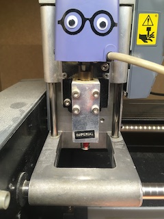
In order to mill a PCB, first you have to prepare the copper plate. Clean it, put it upside down on a towel, stick adhesive tape to it, stick it on the sacrificial layer, then on the bed of the machine. Tighten it carefully.
Start the machine, and open up the ‘mods’ application on the computer. Load the design from a usb. In a sequence of windows you set the right parameters for speed and min and max depth of cutting. There is a default setting, but today and yesterday there was confusion on whether that was the right one for the job. It worked for me, but I am not 100% sure it wasn’t tweaked after the many tries my peers did yesterday.

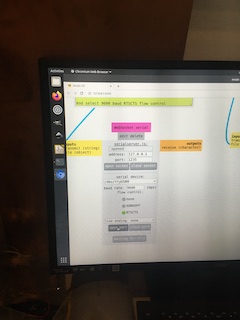
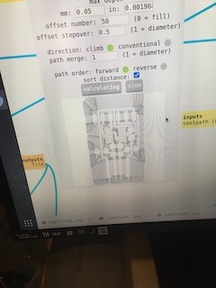
After every change press calculate, and after the final calculate press send. The machine will start milling.

You can check the process by pressing ‘view’ on the machine - it will stop, move the board towards you, and after you vacuum the sawdust to do a visual check, you can press view again and it continues where it left off.
The above process is almost identical for milling the outline to the board - change default settings in mods to outline, and then the MDX20 will cut around the traces in the predefined shape.
Equally important in both instances is setting the right origin - the bit starts at the lower left, so make sure there is enough room for it on the copperplate. I took way too much room accidentally, and wasted half a plate of copper. You can see the trajectory in one of the windows of mods. Today, in the milling the outline of the board, we found a bug. The box in mods showed only one round of the bit where 3 were needed. Going ahead anyway, we discovered it actually did make 3 rounds, so the image mods showed was incorrect. I do not know how to solve that issue.
The bit
One important part of it all is the milling bit you use. For traces it is the 0,4 millimeter, for the outline the 0,8 millimeter. Adjust the settings in mods taking into account using a 1 - or 2-flute bit. In today’s job that did not seem to make any difference.
Changing the bit (it is fragile) involves carefully loosening the screw that keeps it in place, taking it out, and replacing it with the one for the job. The careful part is where, by lowering the bithead(?) with the down-button on the machine to the point where it almost touches the plate, you stop the movement, untighten the bitscrew while holding the bit, and gently lower the it until it touches the plate. Fasten it. Now: press send file on the computer, as I mentioned above in my non-linear description.
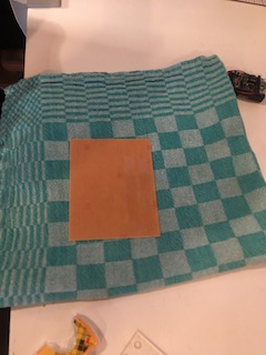
Once both traces and outline (which is called interior for some strange reason) are satisfactorily milled, take the finished board out, maybe with the help of a small scewdriver.
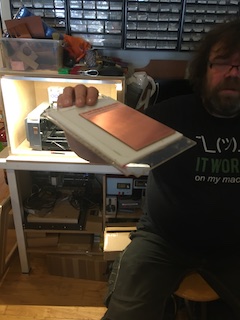
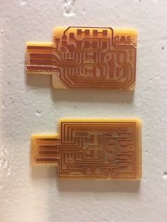
I was quite proud of my first boards…
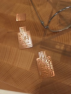
I removed excess copper with a small knife..
and then I started soldering. Of this process I chose not to take pictures, since it slowed down the actual soldering substantially, and I wanted to finish the three boards. Hard part for me was to understand what I was actually doing; what were these parts, what are they called, and how can I find them in the inventory at de Waag. I had to ask my peers and tutors often. At the end of the day I had to accept I couldn’t complete the assignment - one more board to solder, and then the programming and testing part. As I mentioned earlier, I am hoping to catch up next week. Maybe by planning the way we use the lab more carefully, I’ll be able to manage all in the one day I have.
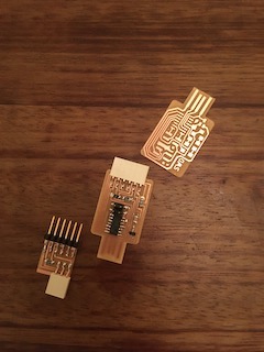
Still. Even without knowing if they will work or not: for me it is quite something, these three little objects.
Edit: a week later.
When I tried to test it, with the help of Bente and later also Saco, it did not work: no led for me. I then learned one of my resistors was wrong, even though I copied the drawing under this link
As Bente pointed out, the resistor in the photograph elsewhere in the git has the right value. I then removed the wrong one by using the heatgun - easier than I thought- and put the right one in. Another issue was that I was unaware the orientation of the leds was important - so I then had to heatgun those as well, and put two new ones. The soldering itself went quite okay, I learned how to use flux this time (a whole lot easier…), and I managed to get things done.
Edit 02-03-22
I finally had time to programme the last board. So first issue was that I really tried to understand how to programme, but I could not get a grip on the things I was supposed to do. Then I asked Henk to do it for me. I found out that, even though it looked kind of ok, I did put some parts the wrong way around. In order to save time, Henk assisted me in removing the parts and putting them back on the right way. After that I replaced some other items, and got the board in working order. It was programmable then, which Henk did for me. It is very far removed from me - so, I documented it, but what it is I do not know yet.
edit 21-06-22
My lack of precision in pics and notetaking and the pressure I usually felt during this process (there were always peers waiting their turn) caused lots of unnecessary mistakes. I resorted to following, except for my own notes, the notes of Benjamin often - but also there I hurried along, and in following his steps sometimes failed to see how he also made errors and corrected himself further down in his description. Major thing I took too long to learn was opening the port in mods before doing anything, and thus ending up in a loop of correcting incorrectable things, restarting machine and mods, etc., sometimes in my anxiety not being able to see whether I already mirrored the design, or if the millingpath was positive or negative. I can say, however, that I actually master the process now; new mistakes are always possible of course.