3. Computer controlled cutting
Yesterday was the first time I went through a regional evaluation, and I must say I was slightly apprehensive. I shouldn’t compare, really, but I the things I see growing alongside of me are impressive sometimes. I think I did well enough, if communicating what and how you did it is the measure for that. My plan is still embryonic, the internal workings of my semaphore are not visible in my model - and that is not only because it looks better this way - I have no clue how to get what I want., but looking at the schedule ahead it seems I might just learn. I struggle with the workload still, and have to adjust my goals now and then, but I’m taking it step by step. I hope I will be able to continue building upon each new skill.
Also yesterday global review, and to me it is a thrill to see my peers from across the globe. It really is a community already, and an exciting one. We got tours through projects and physical places even, and I thoroughly enjoy that.
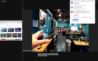
Stern warnings on laser cutting from Neil, and applause from the Spanish minister of….Labs?
The amount of information is still intimidating, but in the step by step I also quickly find I simply cannot do all - how to filter and get to what I need and can manage is going to be a weekly operation it seems.
I better start dating things, this yesterday does not work.
12-02-22
While I wait for the message ‘Deploy in progress’ to disappear (it popped up when I tried to add a new folder, to better organize the images I am uploading)
…I will describe Thursday the 10th, our introduction to real machinery.
The group-assignment was to measure the curve of the lasercutter. After a story that seemed to spell doom for us (“Machine ancient, software no longer supported, controller no longer controlling anything”) proud Henk informed us that after a major overhaul this old giant is again in working order - bricks and heavy metal weights added for extra heroism.
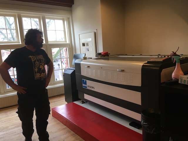
The machine is an old Dutch one, with all electronics completely renewed. I have no pics of that since they are on the inside. The original controller was 18 years old like the rest, and was replaced by a new one.
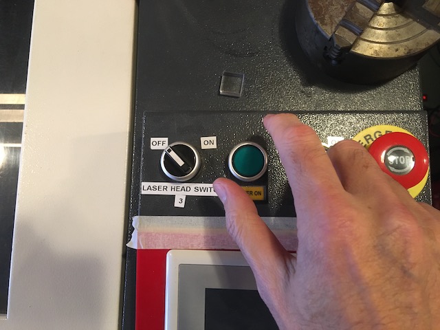
You switch it on with a key, push the On button, and only fire up the laser at the very last moment.
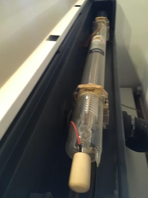
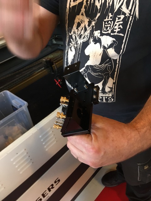
The laser ( Light Amplification by Stimulated Emission of Radiation) is this tube at the back, projecting its pulsating beam onto two mirrors placed at an angle to each other, with the last one aiming the beam directly at the laserhead - that eventually cuts whatever suitable material you placed there.

Here we see it pointing upwards, showing where the lens is. But when running it points downwards obviously. To make sure it is in focus, the custommade widget below is used. Untighten the laserhead, lower it on the widget that is on top of your material, and tighten it again.
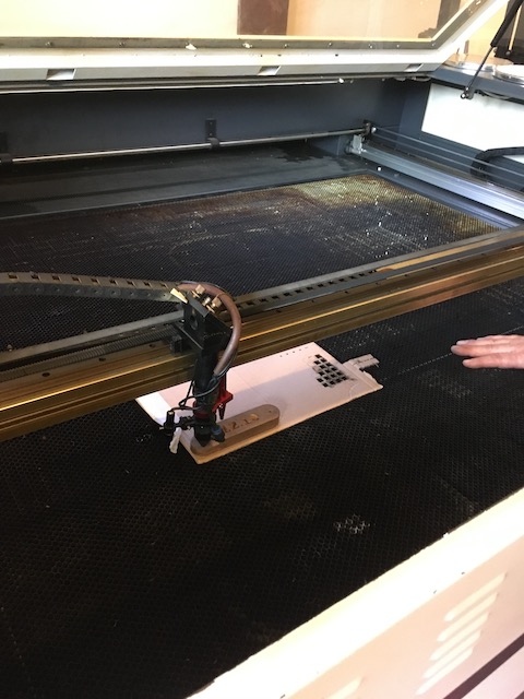

The head is also a bit old, and a new one will replace it soon (below)

Both bed and material are not always straight all the time.
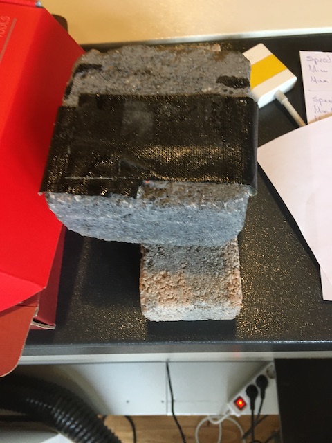
That’s where the bricks come in.
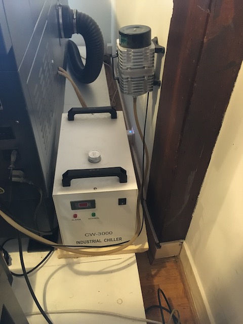
The laser is very hot indeed. It needs to be cooled by this chiller.
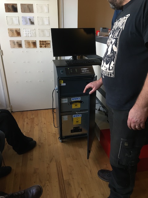
The fumes that arise in the process are removed by this noisy machine. To be gently switched on once the cutter is running.
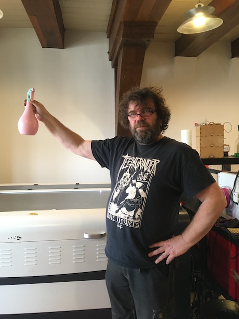
In case anything catches on fire, this plant sprayer is in place. I should check my liability insurence regardless, especially when, with the very first button I pushed, the lasercutter did absolutely nothing. I suspected I ruined it already. Fuse blown, nothing to do with me…
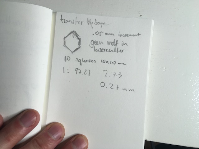
Of course, the machine will also not do a thing if you do not feed it a design. We (e.g. Jonathan) made one for the group assignment, which was to measure the kerf.
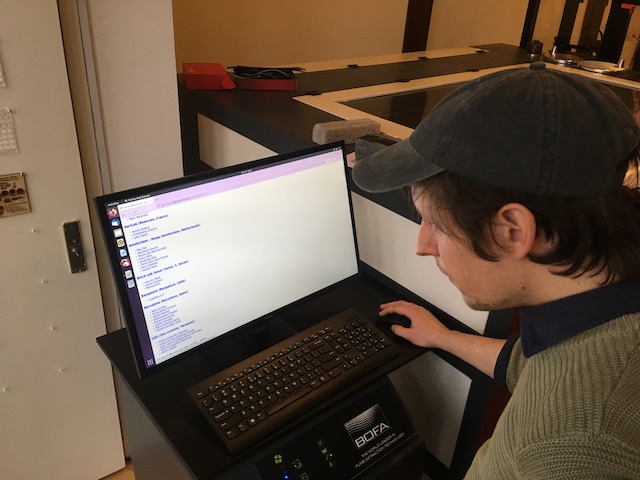
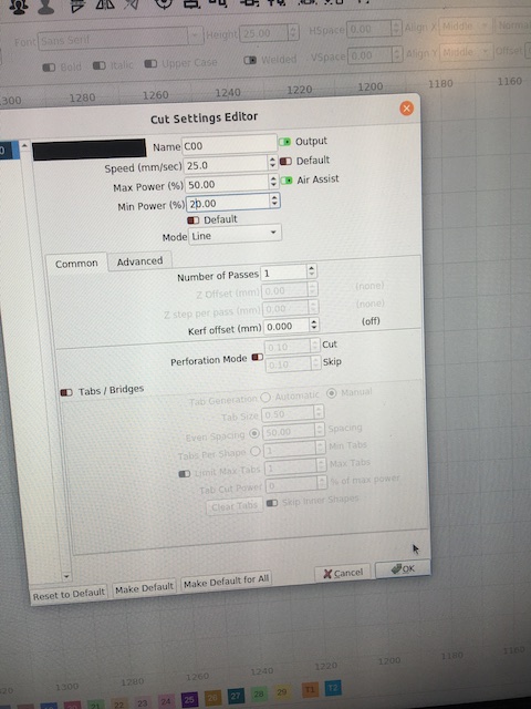
Import the design on the Linux computer into Lightburn, and program the right settings for the material of your choice. You can see how the variables power and speed affect the different materials.
examples:
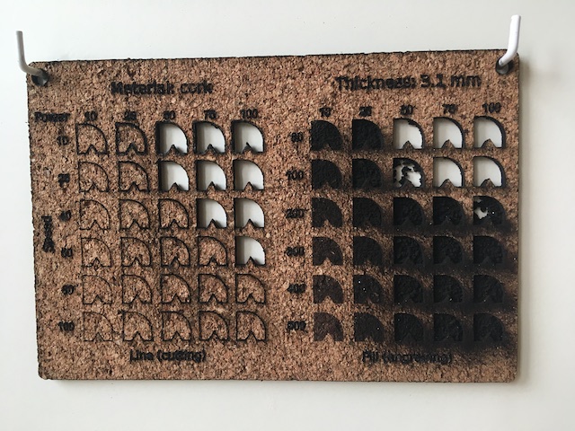
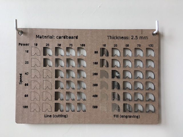
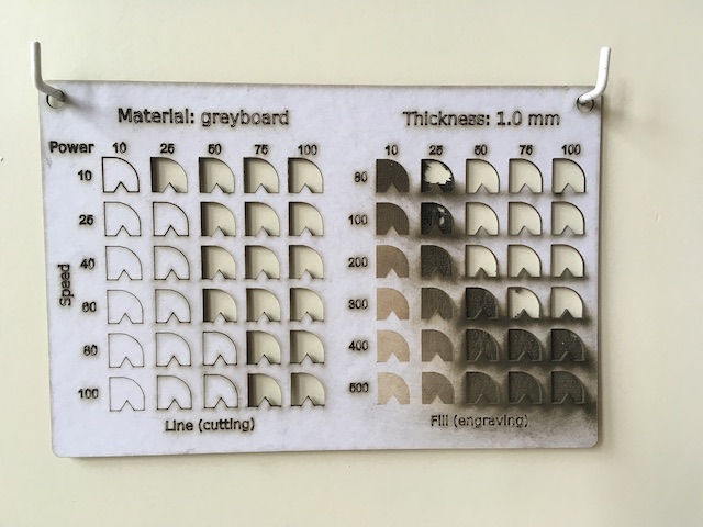
We used 3mm cardboard.
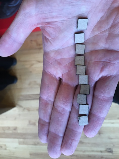
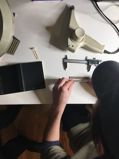
and found the kerf to be…
__12th and 13th february__
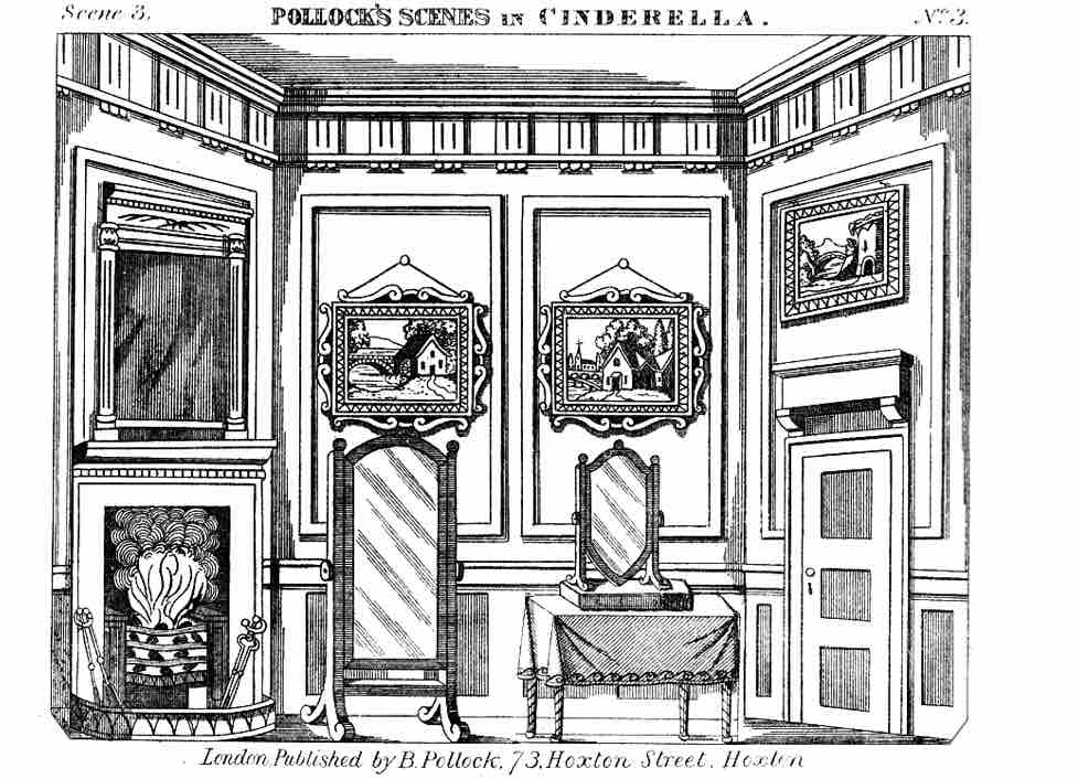
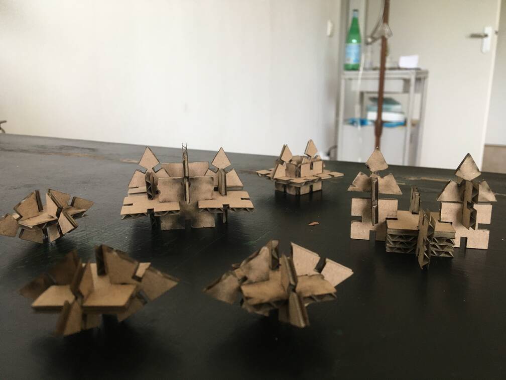
Spent most of the 12th getting the photos downsized and published. Thought about a press-fit kit, but I found it hard to come up with a concept. I wanted to make something playing with perspective, like wings in a theatre..
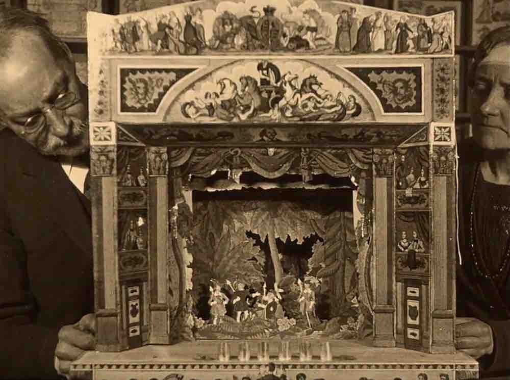
..which evolved into an idea about a shooting range where size and distance to the viewer vary -all of it not very engineerish and very much in line with my trusted way of thinking.
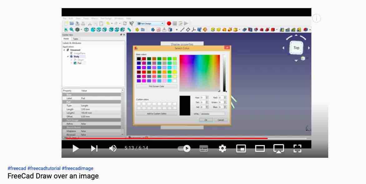
I tried, following a small tutorial on drawing over things in Freecad, but it did not feel parametric at all and I felt sorry for the animals.
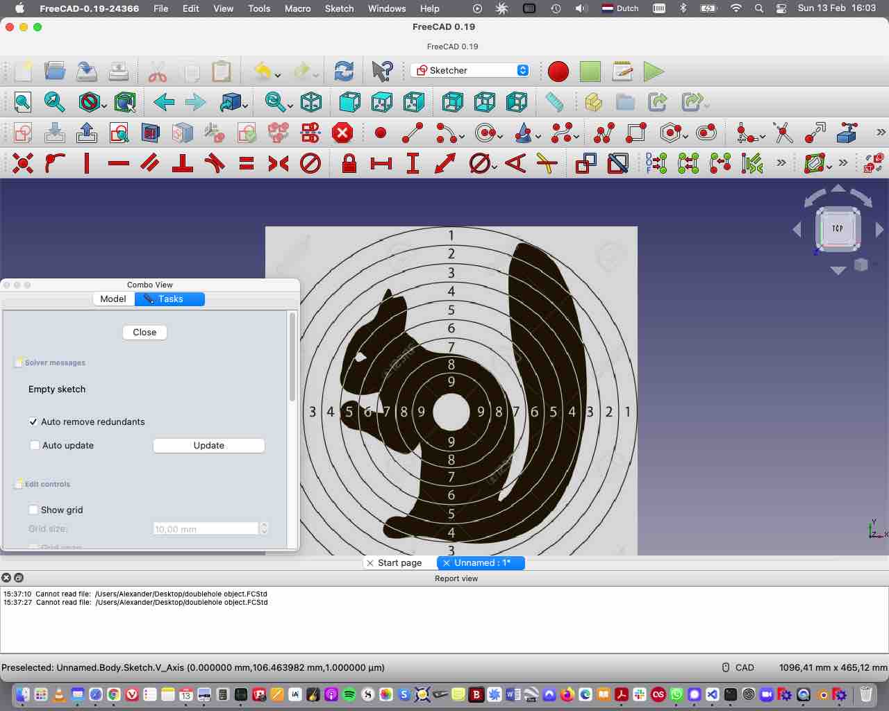
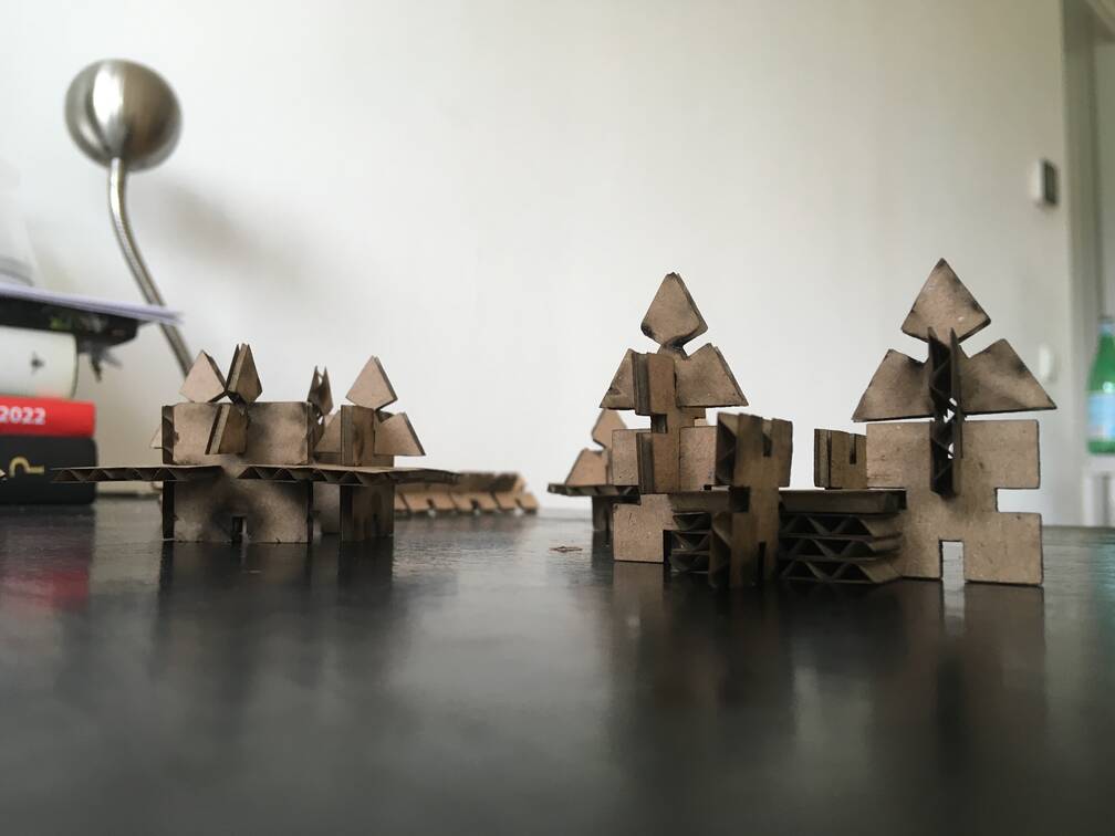
I will now build a frame, with similar elements differing in size, resembling this perspective effect from theatre or garden design. Maybe.
14-02-22
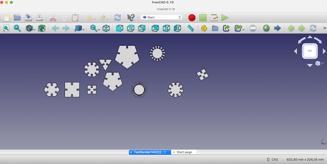
Tsss. A garden or theatre. What was I thinking. Somehow I found this really hard to do. I could not envision any parts, or any whole made out of parts, and I struggled to even get a very beginning. In the end I rewatched Babken’s tutorial in parts again, and tweaked what he demonstrated. Now I have differently sized and shaped parts for a pressfit kit - one that will be rather abstract I’m afraid. ‘Playful’ might be the right term ;)
At least I can try to cut something now, tomorrow.
15-02-22
I went to the Waag to cut the things I designed. It did cut, but it was far from pressfit. I tweaked my design, thought I was adjusting the kerf correctly but I was doing the polar opposite. It took me a few hours to realize that.
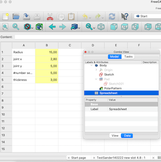
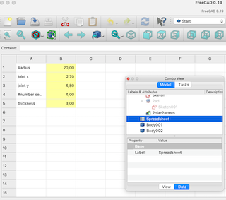
In the images above you can see how ‘parametric’ works: the values you put in there (and in my case the most obvious one is the value for number of segments) leaves the design as such and the relations of it intact, but changes a certain aspect of it. By putting 3, 4 or 5 in the box from my example I got parts with 3, for or 5 segments, same basic size, same slit, but a wholly different outcome. ‘Holistic’ probably is lending the wrong term to describe it in other words, but it is close to changing one aspect (value) changes the whole thing.
Meanwhile I was fighting with FreeCad (issues were , for example, how it defines a simple copy), and then I got the measurements right. It took me 5 or 6 tries at the machine. The next mystery was the lasercutter cut everything twice: it did the exact same trajectory double. Quite baffling. With the help of Michelle we figured out it was because Freecad made double lines in my design (possibly related to the copying issue), and only after removing the duplicates (in the clip the top-ones, that are individual lines instead of shapes) I ended up with a correct design.

Moneyshots

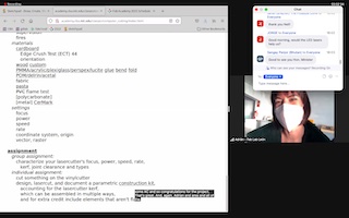
Vinylcutter
Working on individual assignments with several people simultaneously sometimes means cutting corners a bit - in order to save time e.g.
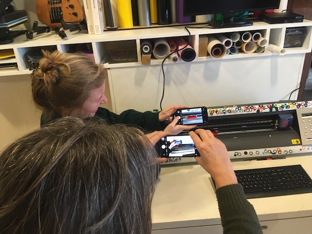
For me this was the case with operating the vinylcutter. Helped by the example our peers gave and by Nadieh Bremers’ excellent step by step guide
we collectively cut one another’s designs. I did not take that many photos of the process.
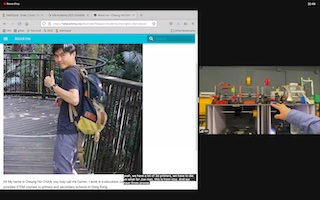
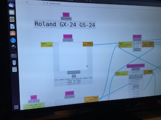
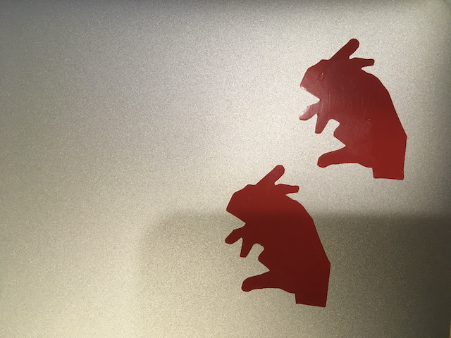
The image I fed into the machine is a jpeg I found online of the famous handrabbithand - I turned it into an svg in order to process it - I’m afraid I do not remember how I did that, most likely an online tool.
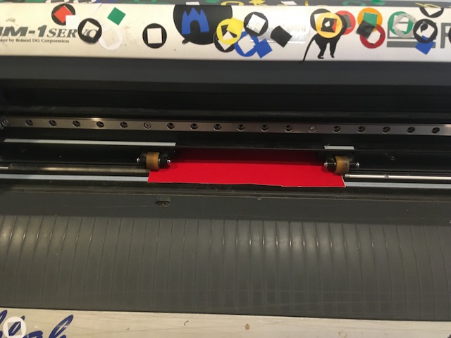
Using the machine:
-Switch on the Roland GX 24. -Feed the material from the back -Align the rollers that hold down the material within the borders that are indicated by white markers. -Lock your vinyl with the handle at the back.
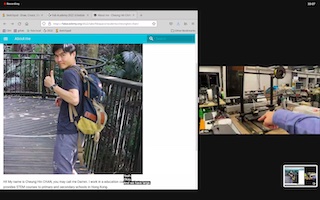
-Answer roll or piece. -Move the knifehead, and set the origin. -Do a testrun, and adjust the force of the knife when necessary (like when you cannot peel off your design easily)
-Open mods programs>open program>cut> choose svg/png>calculate>set/check parameters> send file>it cuts.
Once the cut is satisfactory, eject the vinyl from the cutter by pressing the up/down arrows.
freecadfiles1 freecadfiles2 freecadfiles3 vinylcutterfile