Week 4: Electronics production
Group assignment:
Characterize the design rules for your in-house PCB production process: document feeds, speeds, plunge rate, depth of cut (traces and outline) and tooling.
Document the workflow for sending a PCB to a board house
Document your work to the group work page and reflect on your individual page what you learned
Individual assignment:
Make and test a microcontroller development board
Group assignment:
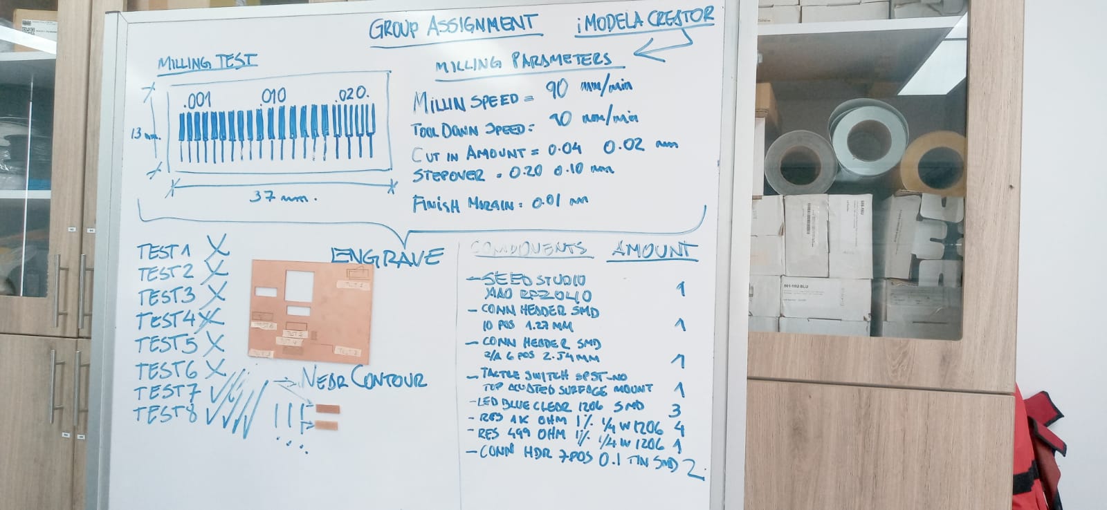
We have used the srm-20 mini milling machine
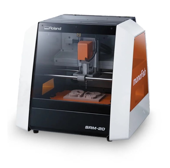
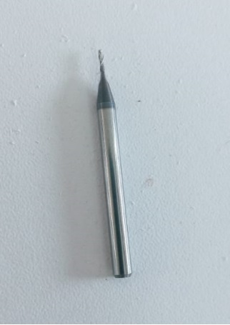
 We use two types of milling cutter and they are 1/32 and 1/64

We use the srm20 software and place the parameters in the x y and z axes then we set so that the milling cutter starts its journey
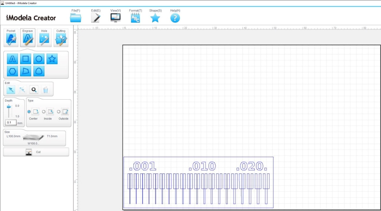
We proceed to perform the test in the following image using the srm-20

We use the modela creator software where we describe the cutting parameters of 0.1 mm and choose to cut in contour
several errors came out
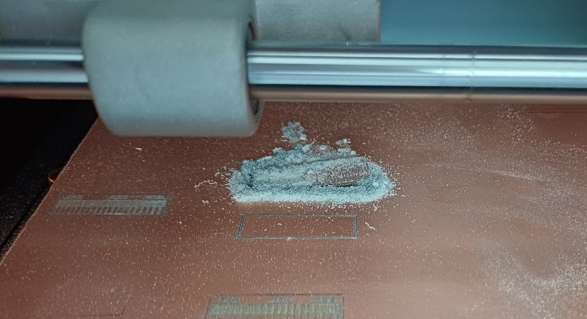
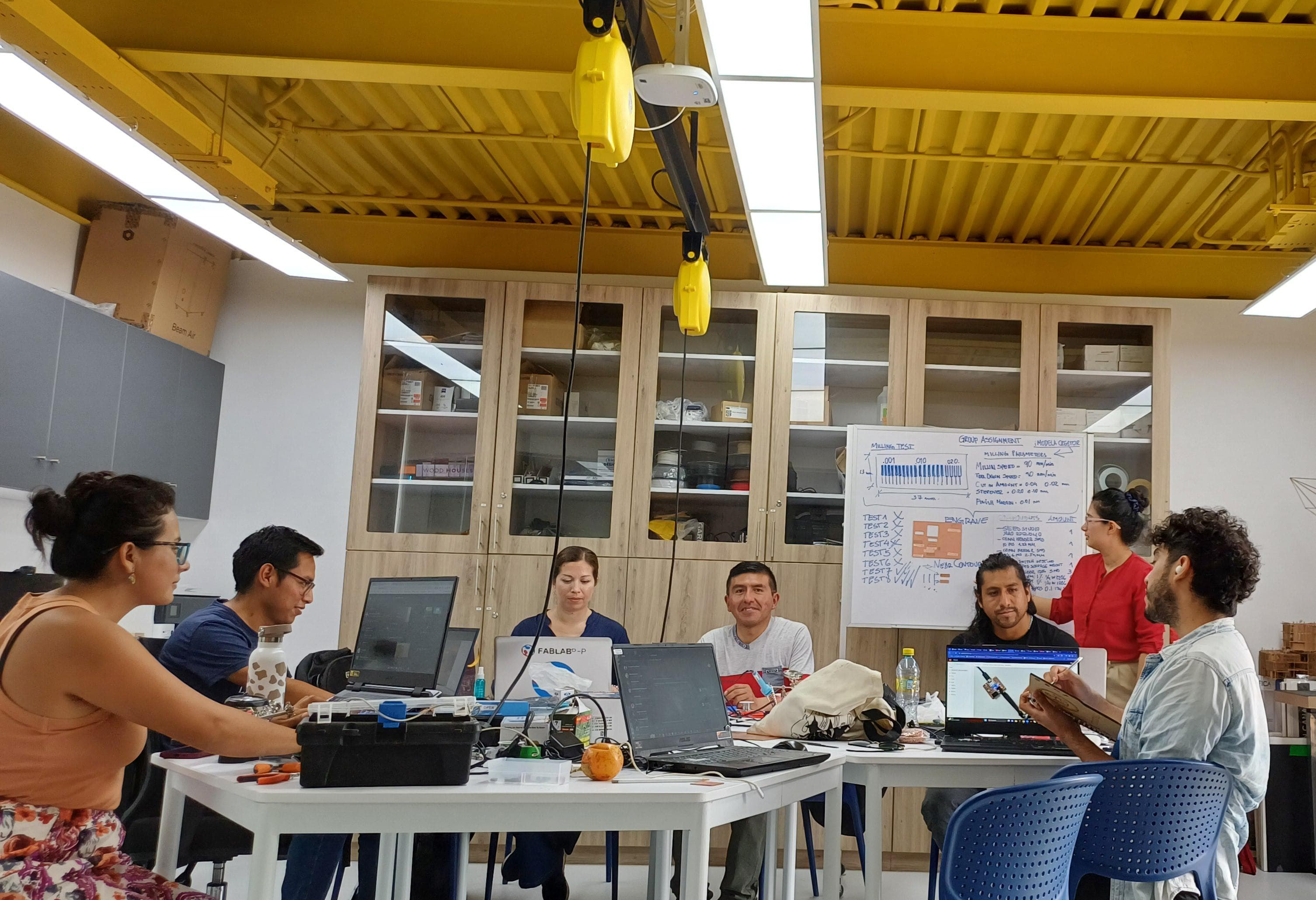
Several tests were carried out with the support of our colleagues

After several attempts since the problem was the offset that could be modified in the software and it came out as follows
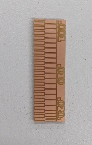
To achieve this we had to carry out our test board with our colleagues
Card manufacturing in a dedicated company
STEP 1:We have to Export the file with gerber extension
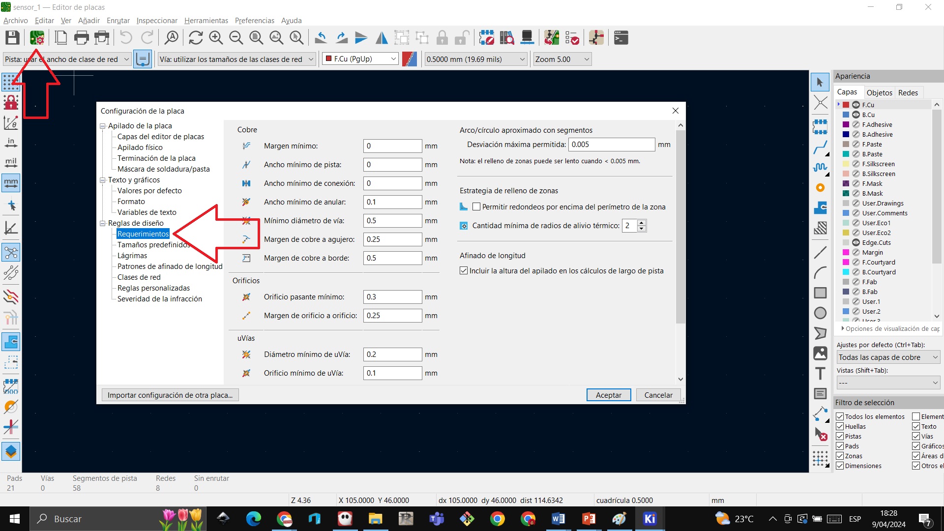 STEP 2:We have to change the parameters at least 0.1 so that the traces can be displayed
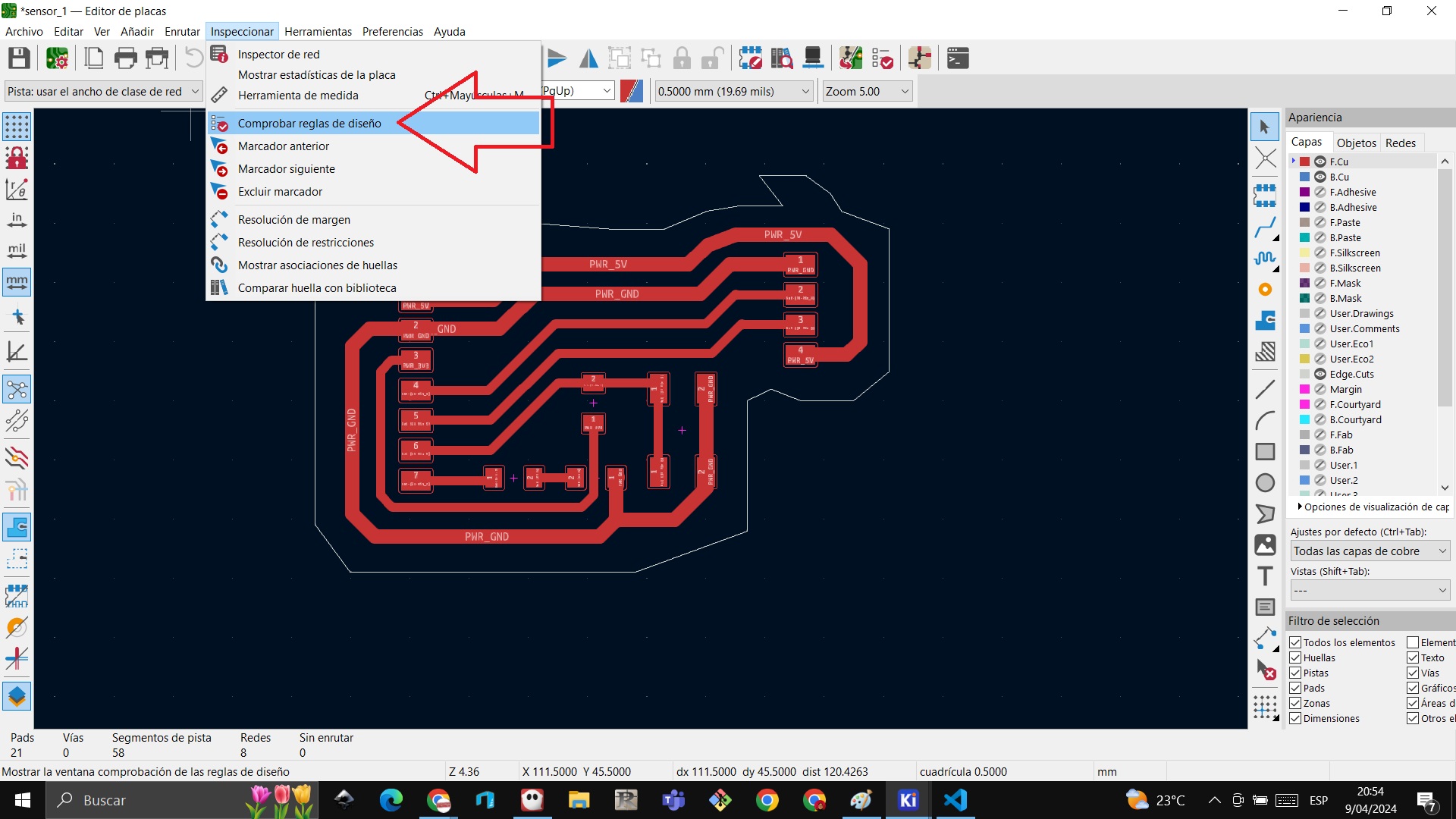
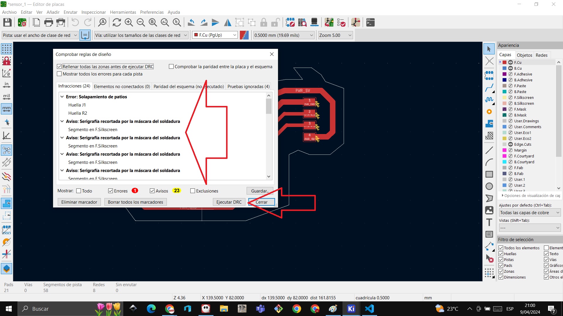
 STEP 3: Checking design rules and executing DRC to see how my board appears, there we observe that there is 1 error, that is, some board is colliding and we go on to review
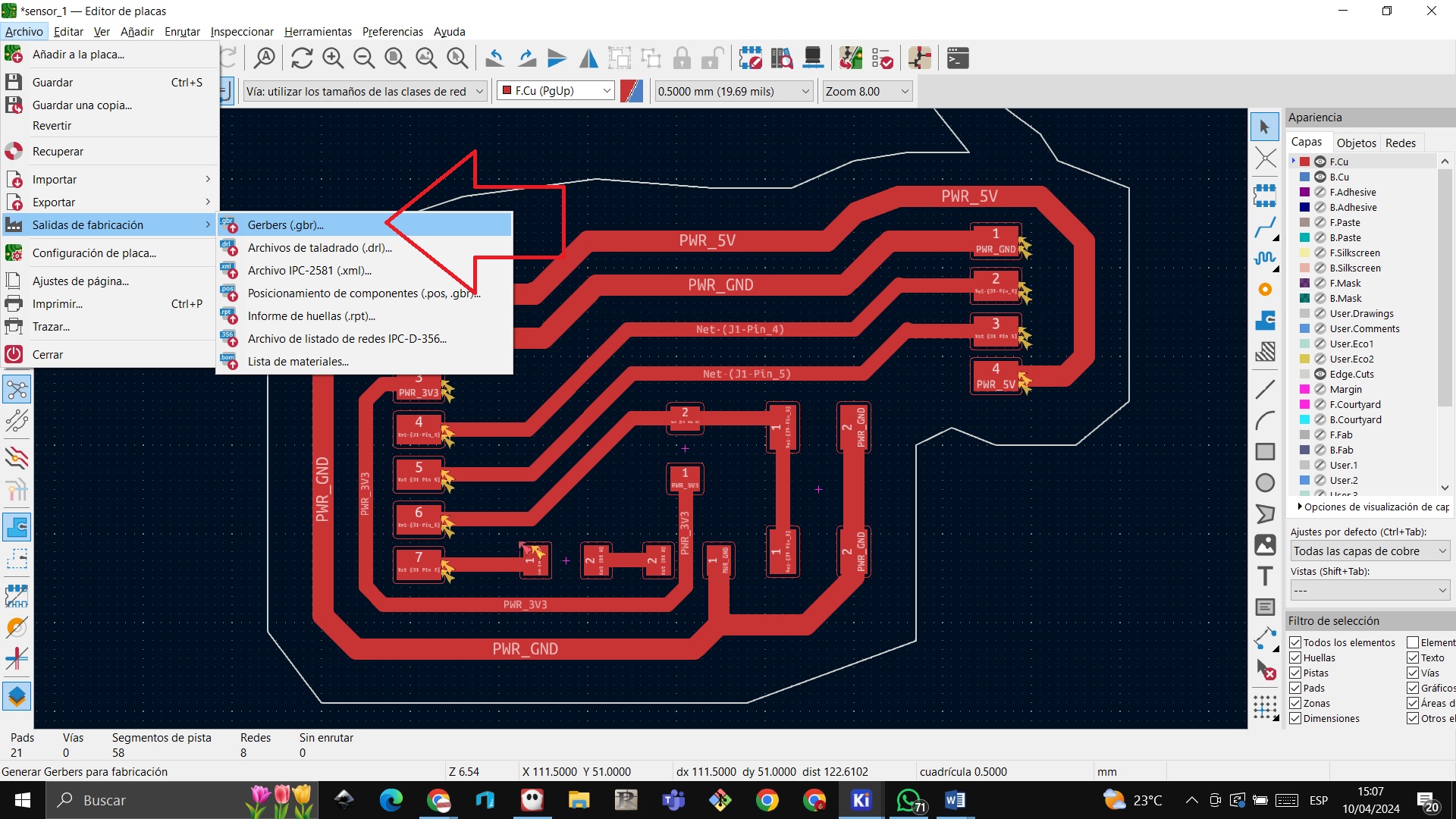
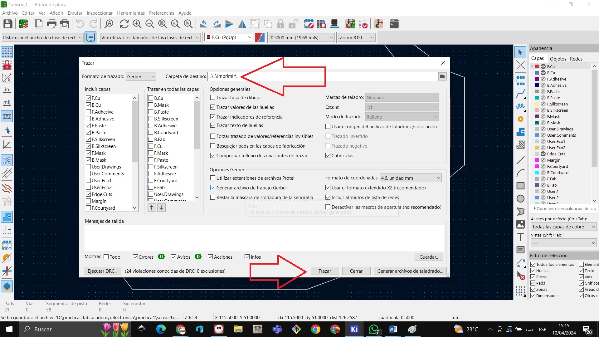
 STEP 4: I generate the gerber file in file/manufacturing outputs/gerbers, choose the folder and click on plot
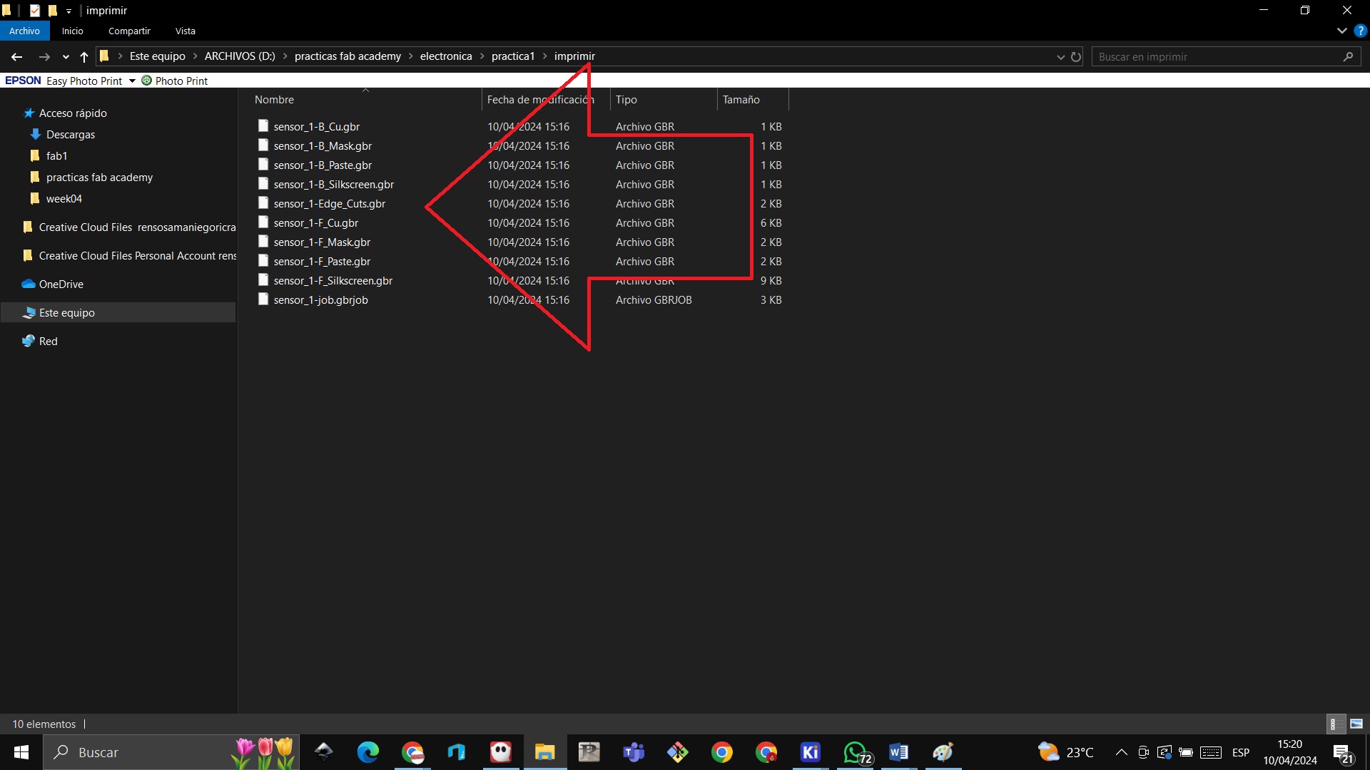
 STEP 5: We verify in the folder that the gerber components were generated
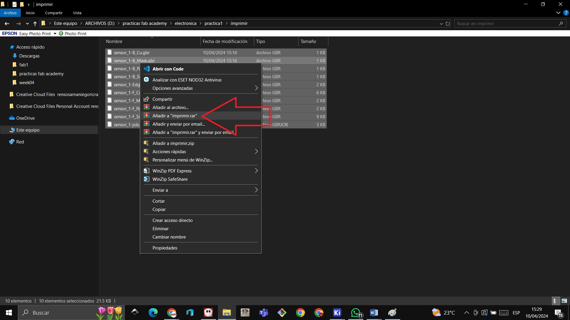
 STEP 6: We compress the file with winrar to export it to a company to design our board
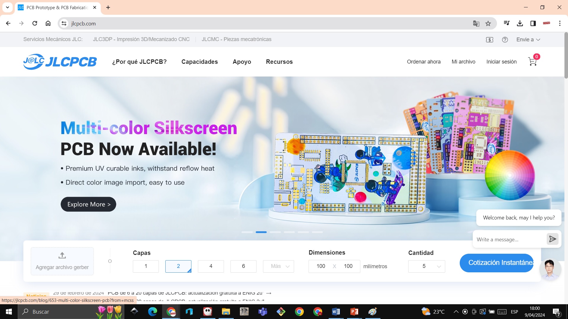
 STEP 7: We enter the website jlcpcb.com to be able to quote the plate
https://jlcpcb.com/
STEP 7: We enter the website jlcpcb.com to be able to quote the plate
https://jlcpcb.com/
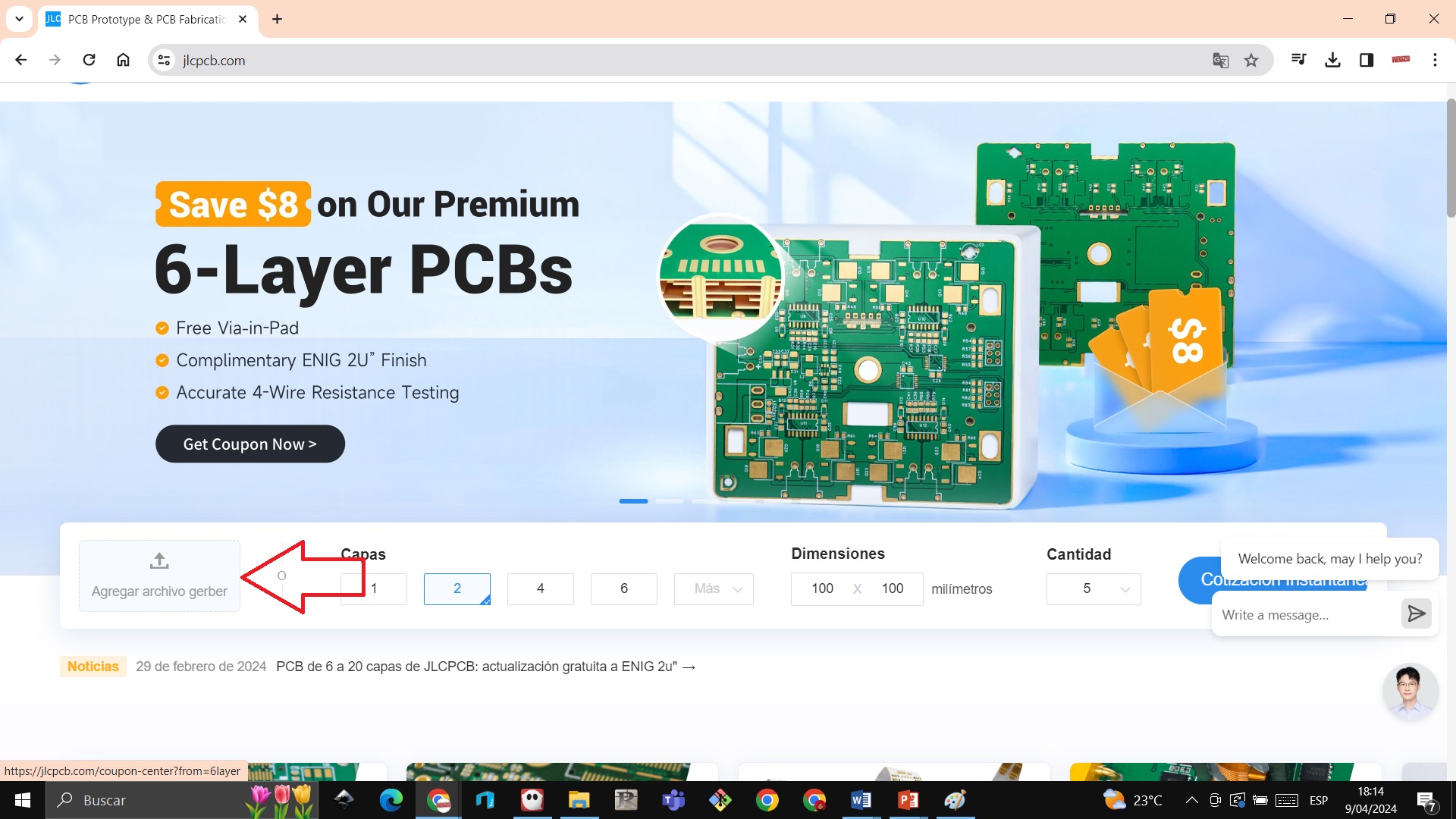
 STEP 8: We add the gerber code
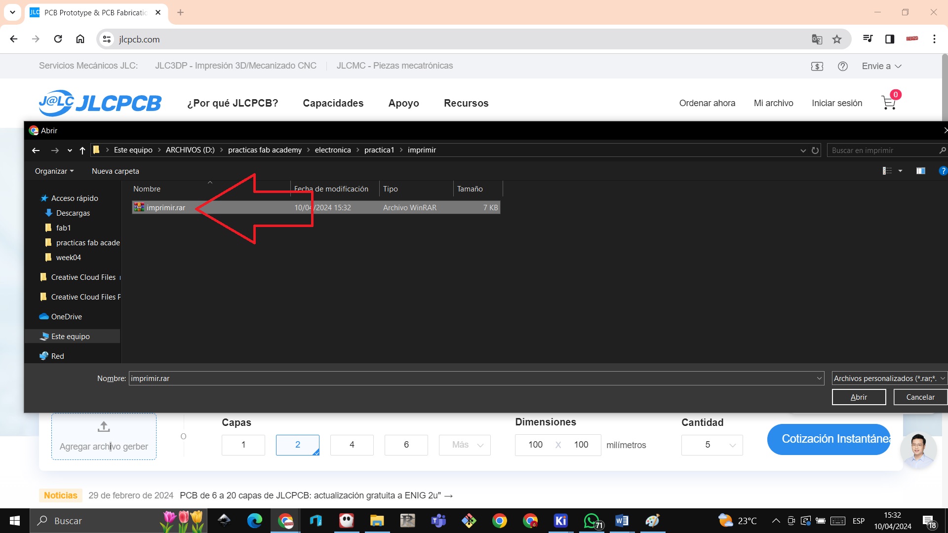
 STEP 9: We import the compressed file to upload to the company page and thus request the design of our plate
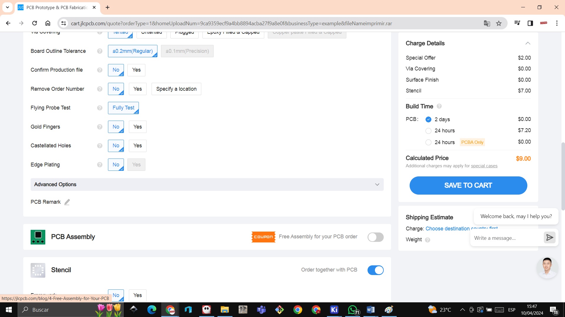
 STEP 10: Once the file is loaded we can view our design in our case our llama designed representing the Huayllay Stone Forest we get the amount of 2 dollars and more the stencil is 7 dollars

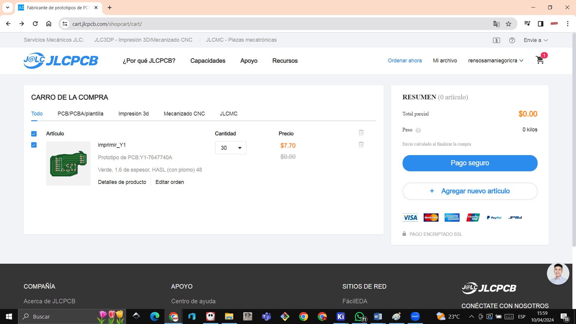
 STEP 11: We click on pay and we have to log in with our Gmail account to pay with a credit or debit card

Individual assignment:
Here we are going to understand how electronic components work, but since we still do not have the materials, we are going to carry out work with the computer
milling with software mods
STEP 1: We download the image to be able to mill that QUENTORRES provided us
 STEP 2: We open the modsproject.org pages and right click
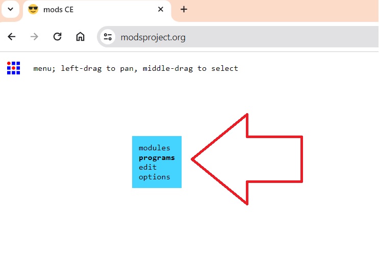 STEP 3: Now we click on open program
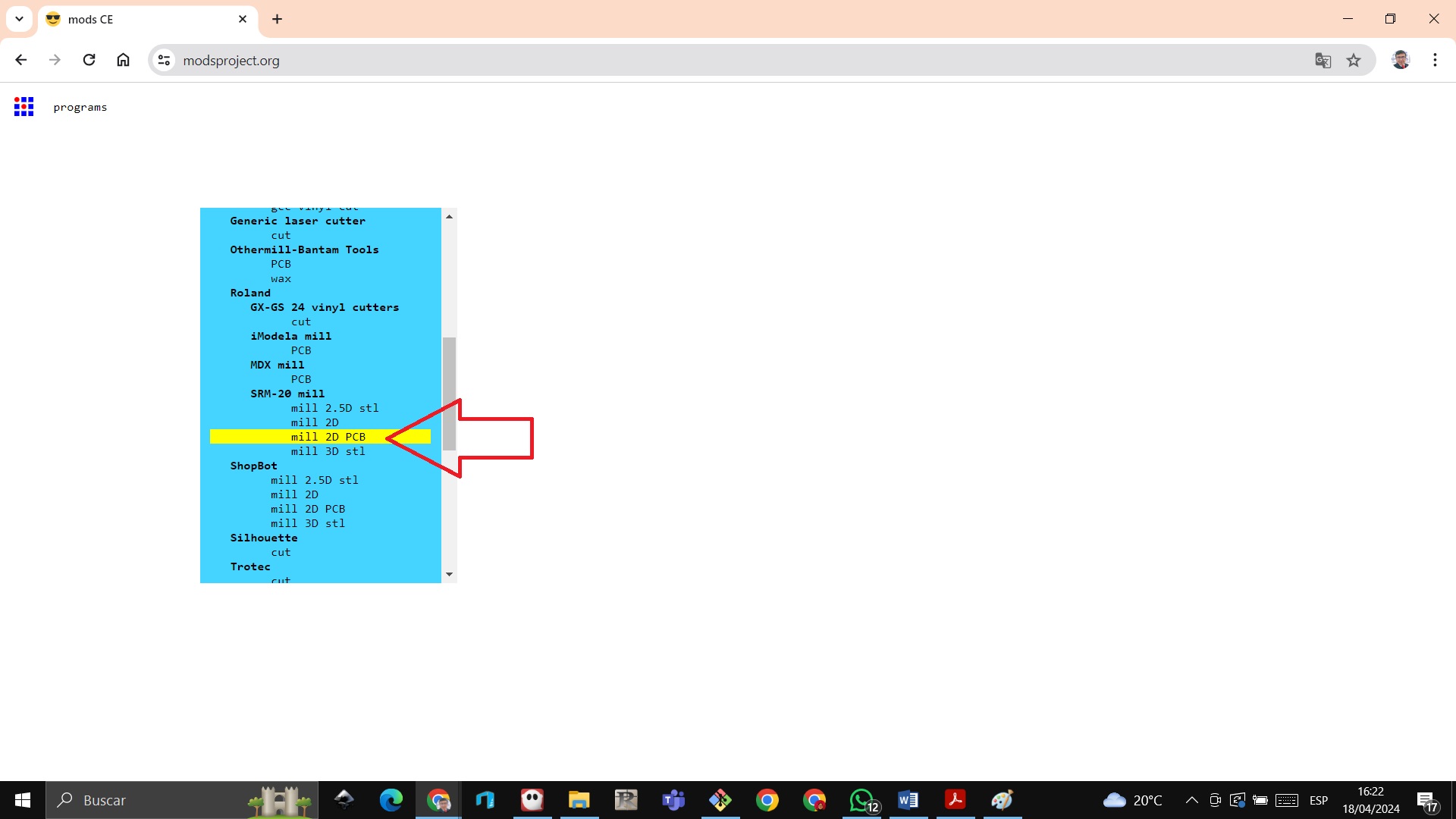
 STEP 4: Now we click on mill 2d pcb
 STEP 5: The following image appears
 STEP 6:
Arrow1: Load the image where it needs to be in a png image.
Arrow_2: We select which milling cutter we are going to use, in this case it is a thin milling cutter (1/64)
Arrow_3: We open the output so that it can download the gcode
Arrow_4: We select the x, y, and z axes to choose where we will start milling.
Arrow_5: We click on calculate to download the gcode and load it into srm 20
STEP 6:
Arrow1: Load the image where it needs to be in a png image.
Arrow_2: We select which milling cutter we are going to use, in this case it is a thin milling cutter (1/64)
Arrow_3: We open the output so that it can download the gcode
Arrow_4: We select the x, y, and z axes to choose where we will start milling.
Arrow_5: We click on calculate to download the gcode and load it into srm 20
 We observe the strokes that the strawberry will make to make the quentorres card
 STEP 7:Once the software is open, we put the plate and stick it with tape so that it does not move
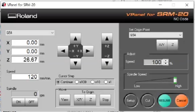
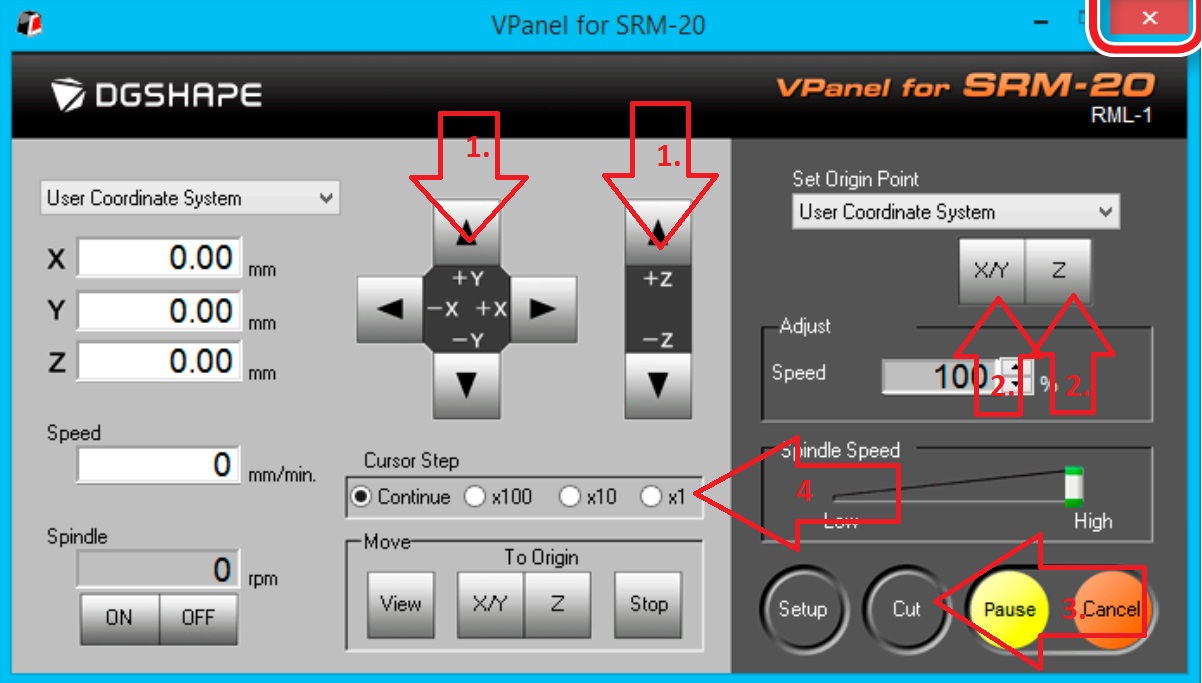
SETP 8: STEP 8: We connect with the software:
Arrow_1: Used to calibrate where we want to start milling the plate, we have the x,y,z axes.
Arrow_2: We set the x,y,z axes to see where it starts.
Arrow_3: Here we execute the program so that it starts with the cut without first in the setup button we have to load the gcode file that comes out with an .rml extension from the mods software
Arrow_4: It is to see the speed at which the cutter moves and when it is continuous it moves at a higher speed in the x,y,z axes.
STEP 7:Once the software is open, we put the plate and stick it with tape so that it does not move
SETP 8: STEP 8: We connect with the software:
Arrow_1: Used to calibrate where we want to start milling the plate, we have the x,y,z axes.
Arrow_2: We set the x,y,z axes to see where it starts.
Arrow_3: Here we execute the program so that it starts with the cut without first in the setup button we have to load the gcode file that comes out with an .rml extension from the mods software
Arrow_4: It is to see the speed at which the cutter moves and when it is continuous it moves at a higher speed in the x,y,z axes.
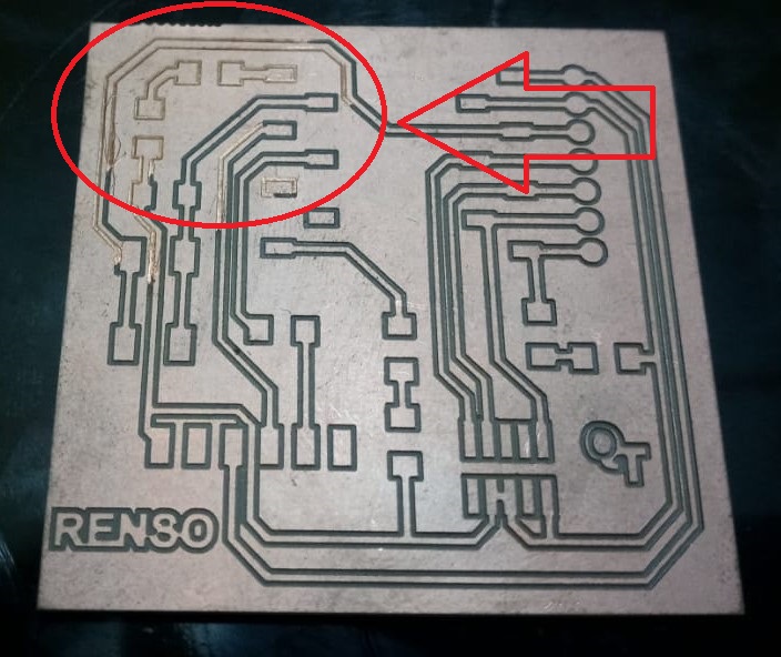
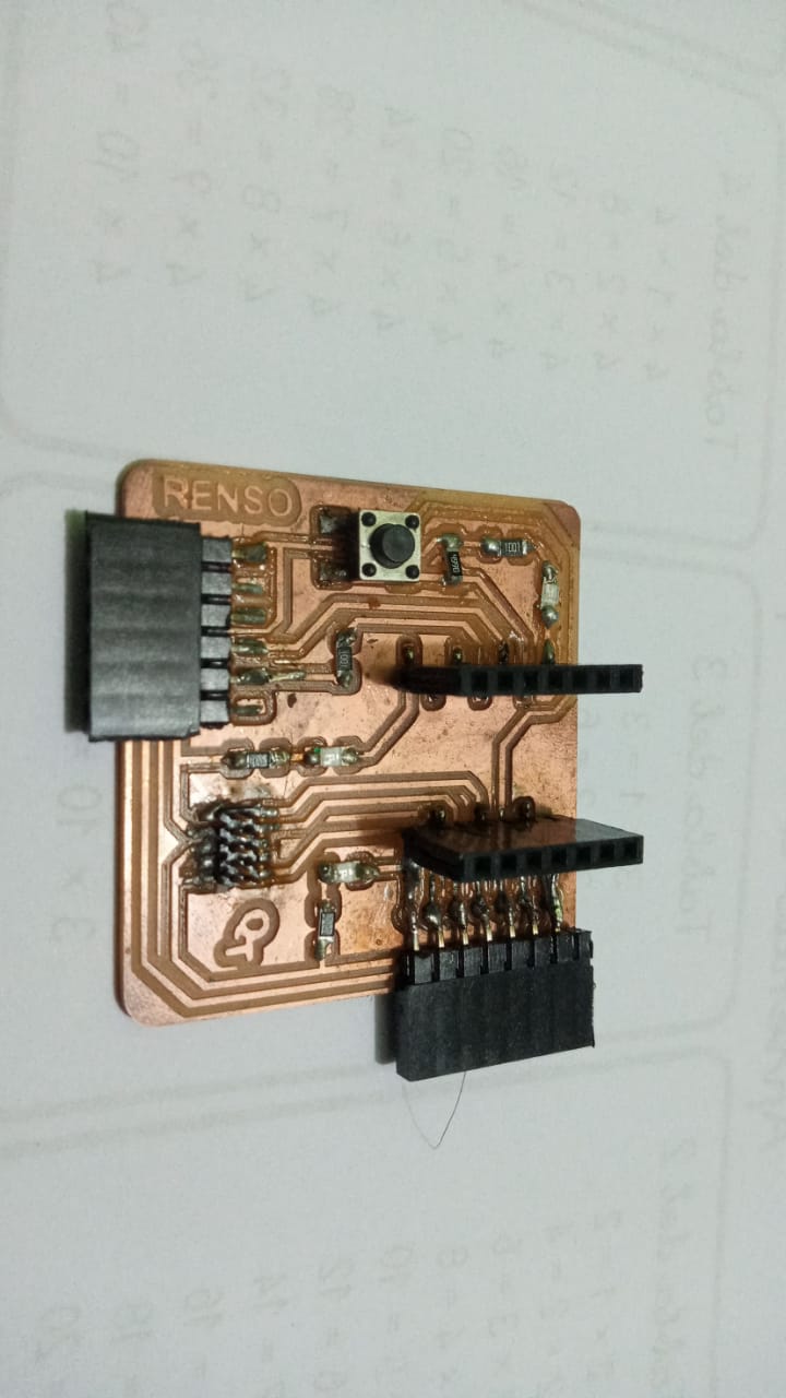
 STEP 9: We check how the work turned out and we observed that in the upper right part it did not turn out well and we have to re-mill.
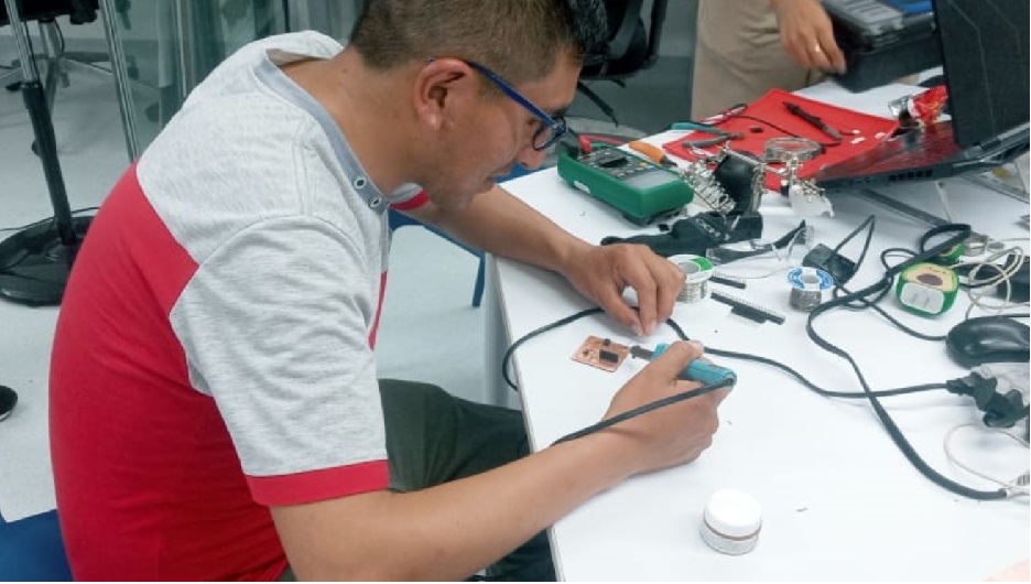
 STEP 10: Now that we have the board we have to solder the components such as: resistors, LEDs, sockets, switches for which we used cautin, tin and paste. It was very complicated since it was the first time I soldered.

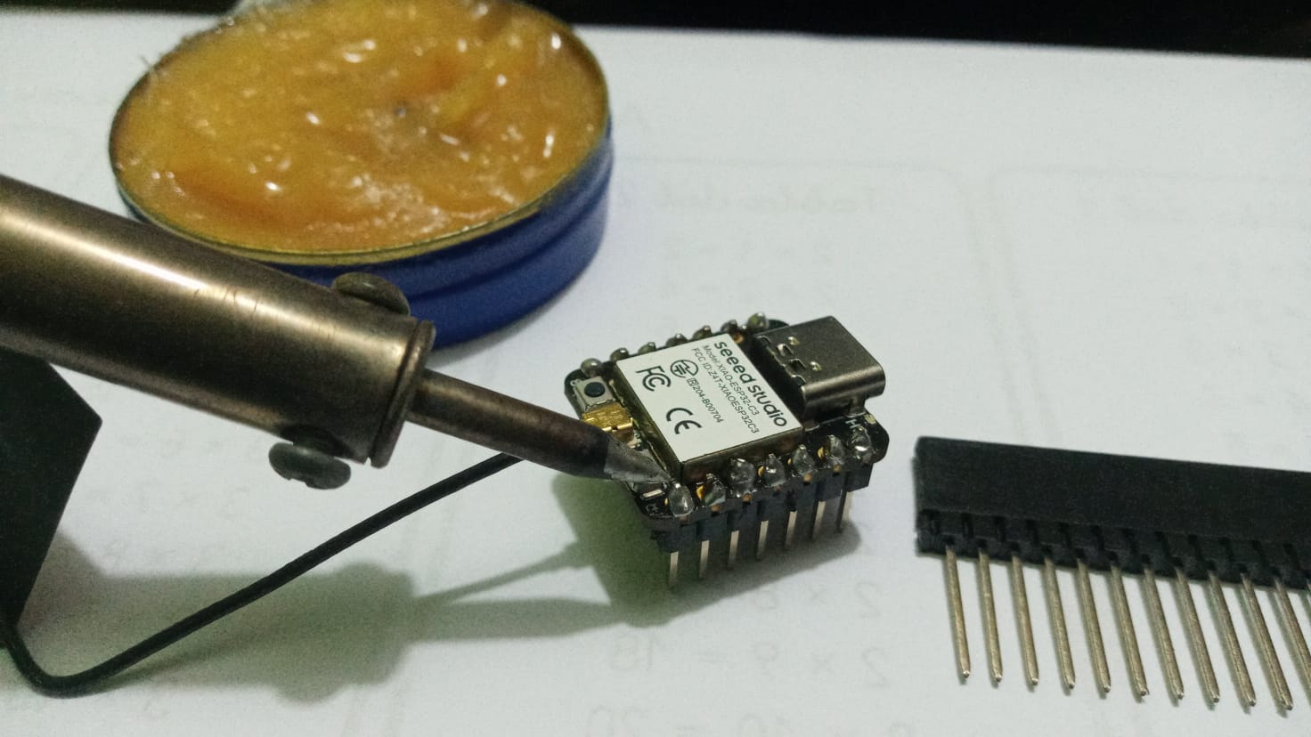
 STEP 11: We had to be precise when soldering since the XIAO ESP32 3C had to fit into the sockets
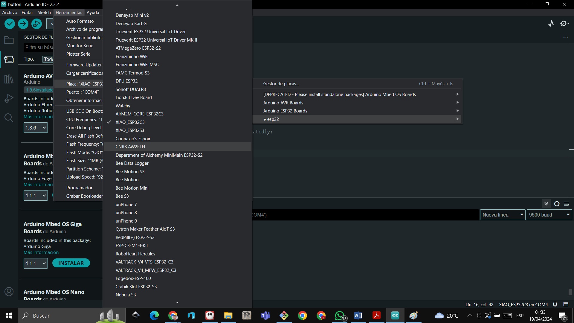
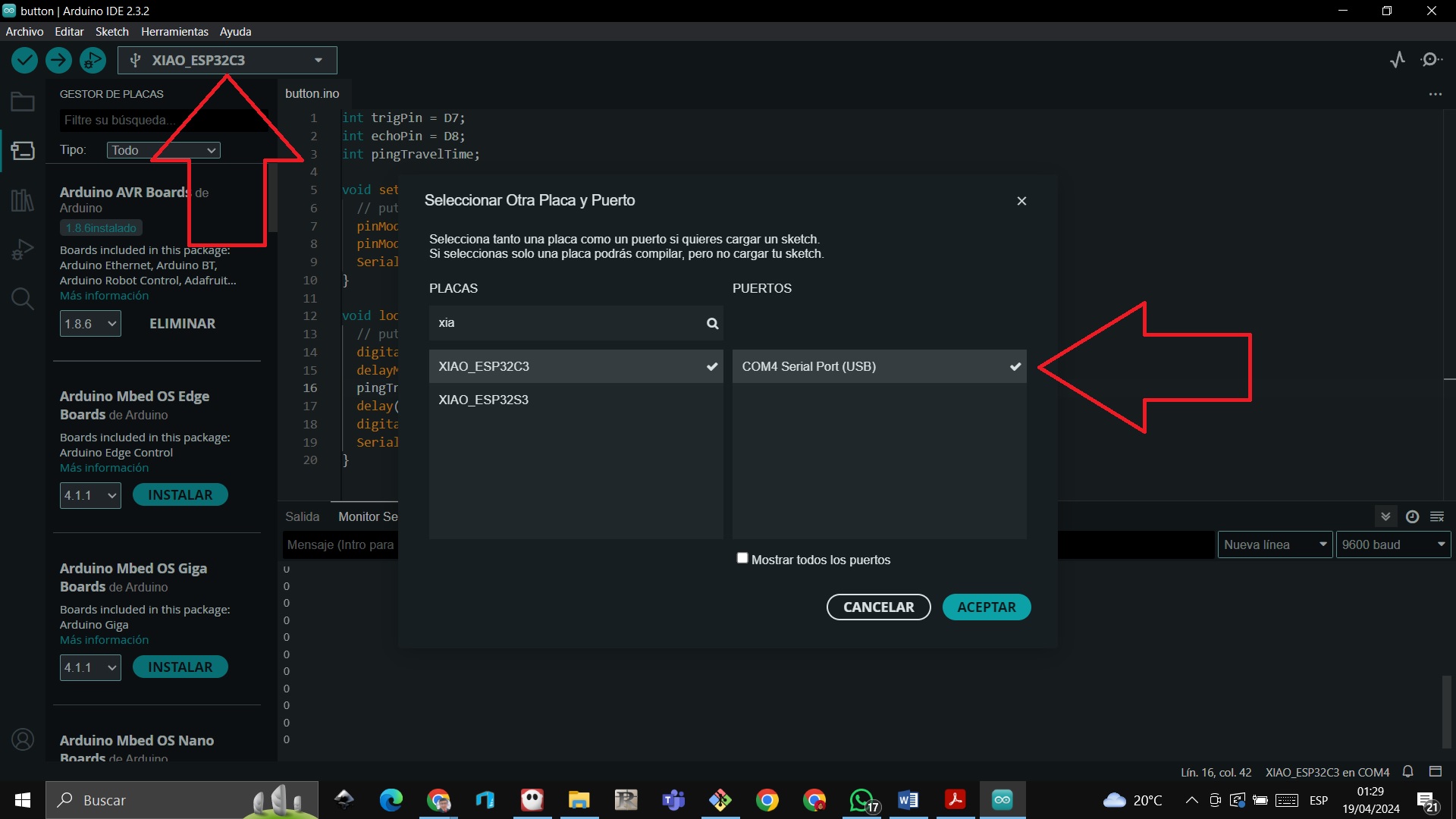
 STEP 12:We are at the moment of truth to test the quentorres card with the operation of the XIAO Microcontroller, we open the arduino software and look for the XIAO ESP 32 3C and connect it
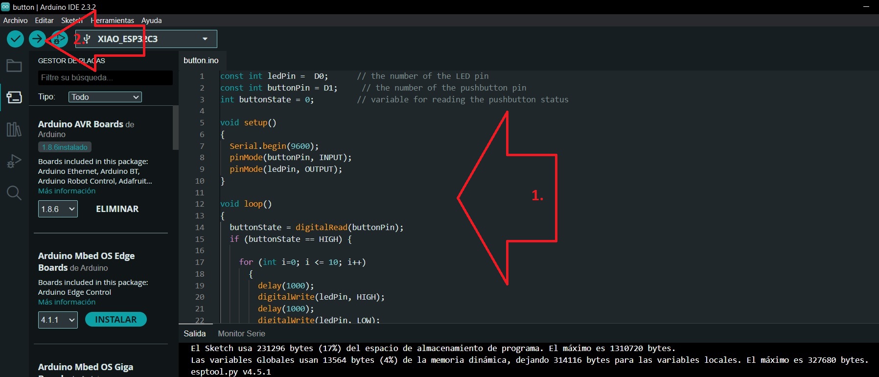
 STEP 13: We write the program where it tells us if we press the switch it turns the LED on and off 10 times with an interval of 1 second and if the button is not pressed it turns off the LED, then we run the program with the load command that is located in the upper left.
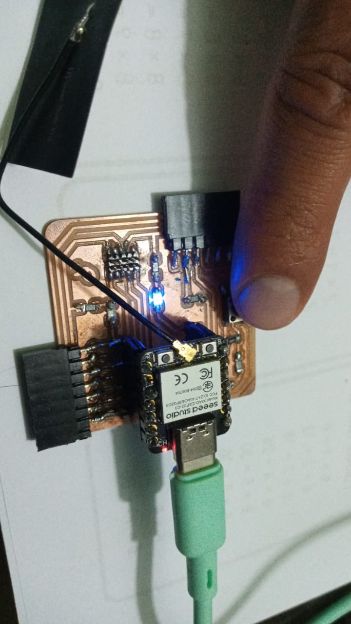
 STEP 14: We verify on the XIAO ESP32 3C
Conclusions
Using the SRM-20 Mini Milling Machine has been a very titanic task to use and understand the software and at the same time gratifying when it was verified which parameter to use in the z axis to be able to mill the plate since several times the 1/2 milling cutter broke. 64 since it was placed very low and another detail is in the welding there were difficulties at the beginning, the welding was achieved not so excellent but it connects