Week Eight
8.Computer controlled machining
I.GROUP ASSIGNMENT
a.CNC
The CNC by its definition means in Computer Numerical Control machining. in other words, it is a machine controlled by a computer, but not just any computer, but one that contains the unique software of the machine and is accompanied by its joystick.
CNC is used in industries whose manufacturing processes require the use of computers to control machine tools (Tools that can be controlled in this way include lathes, mills, routers and grinders).
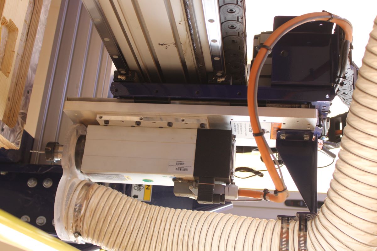
b.ShopBot
Shopbot being a CNC machine, it works under the numerical control of its computer. A well-defined computer program for an object on the machine. They are programmed in G-code. This code particularly controls all the functionalities such as the speed of movement of the drill, its locations, the coordination of the movements of the router and this with exact precision. Shopbot's CNC machining is used in the manufacture of wooden, metal and also plastic parts.
First, a computer-aided drawing (CAD) is created in 2D or 3D, and then a machine-recognized G-code is created. Then we load this program into the machine. After loading, an operator does a test called Cutting Area, running a program to make sure there are no issues. This is a very important step because any error in the speed and position of the tool could lead to damage to the workpiece or even damage to the machine.
c.Advantages of cnc
Like any other CNC machine. SopBot has many advantages. Because CNC machining is more precise than manual machining and can be repeated exactly and as much as you want. In addition to its quality of precision, CNC machining manages to reproduce really complex shapes, which would be impossible manually.

It is used for the reproduction of 3D objects. This is all the reason why the CNC is used for work requiring a high level of precision or very repetitive tasks.
d.The Sacrificial Layer
Shopbot machinery bed is metal so to protect this bed we have to place a flat layer of plywood over the metal bed which is the sacrificial layer. This layer is useful in the case where the end mills plunge deliberately or by default in the thickness dimensioning of the part to be machined, the bit at the end will cut into the sacrificial layer.
This is why this sacrificial layer is very important when cutting, so our workpiece is always placed above it.
CNC Milling Process
•CAD model design
•Convert CAD model to CNC program
•CNC Mill Setup
•Execution of the milling operation
•Feed Rate
•Coordination
•Site
•Speeds
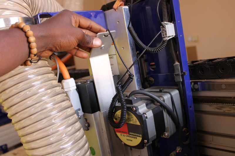
e.Router
A router typically features a variable speed motor, plunge height adjustment (other models are rather fixed) and a collar, it also has a conical spring which, when compressed, creates friction enough to hold the countersink bit in place.
f.TEST
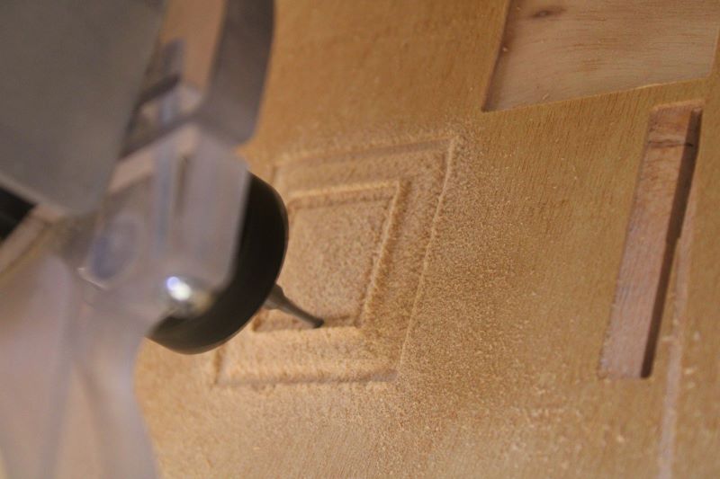
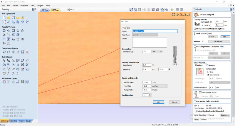
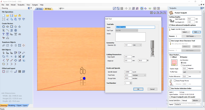
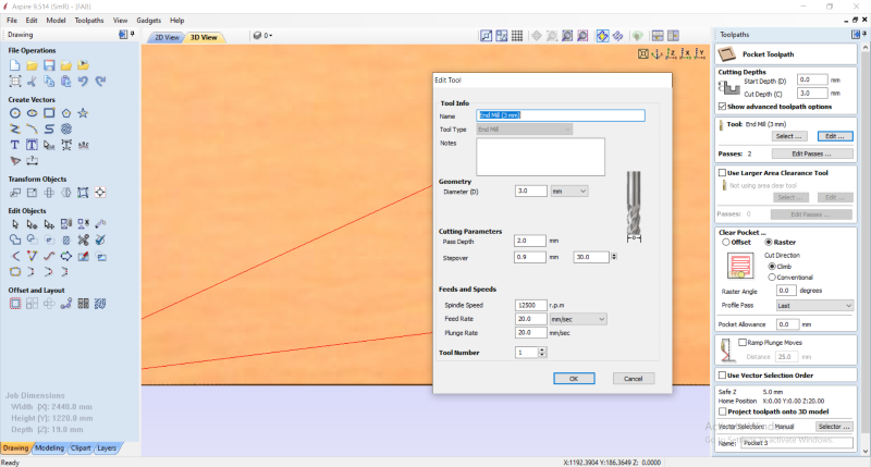
We first created models through the Aspire software. We created simple shapes such as squares and circles, first by opening the aspire software. with the felt on the left job Setup, we have specified the thickness of our board which is represented by the Z axis of 18mm, then its length represented on the x axis is 2440mm and its width represented on the Y axis is 1220mm, then the starting point of the bit in XY Datum position.
g.Router travel direction
To perform a cut or an engraving, it is important to specify the direction of travel of the router in relation to its trajectory of your design, i.e. if it were to follow the left side of the line, it would be an uphill cut, if it were to follow the right side of the line, it would be a conventional cutting motion.


If you want to cut out your shape instead of removing material inside the lines, the toolpath to use would be called a profile (or contour). We have carried out engraving and cutting tests of the same dimensions with the different trajectories of the routers.
h.Type of Drill Bits and Number of Flutes
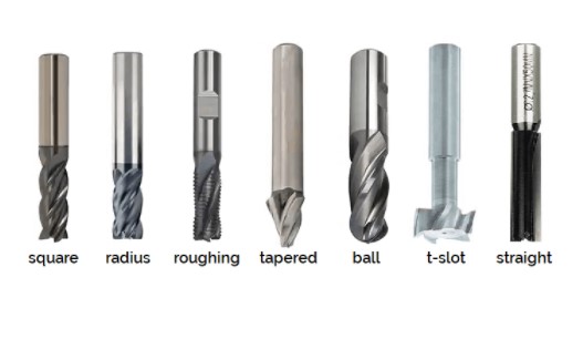
There are as many types of cutters as possible cutting operations: profiling, contouring, grooving, counter-boring, drilling,... Here is a brief overview of the main ones. Square end mills are the most common and can be used for many milling applications including grooving, profiling and l. Corner Radius Cutters have slightly rounded corners that help distribute cutting forces evenly to prevent damage to the cutter and extend cutter life. They can create flat-bottomed grooves with slightly rounded inside corners. Roughing/roughing cutters are used to quickly remove large amounts of material in more demanding operations. Their special shape greatly reduces vibrations but leaves a rougher finish. Taper end mills are center cut tools that can be used by plunging into the material, and are designed to machine angled slots. They are generally used in the machining of moulds. Ball end mills have rounded ends and are used for milling 3D shapes or rounded grooves. T-slot cutters can easily cut precise keyways and T-slots to create work tables or other similar applications. Straight cutters have a zero degree helix. They work well for materials where the lifting effect of spiral teeth (at an angle) could cause undesirable results, such as with wood, plastics and composites.
i.Our bit
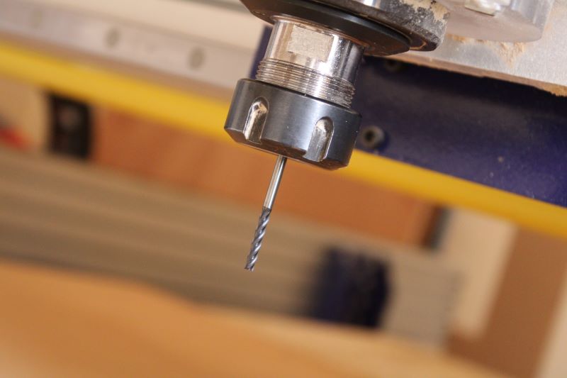
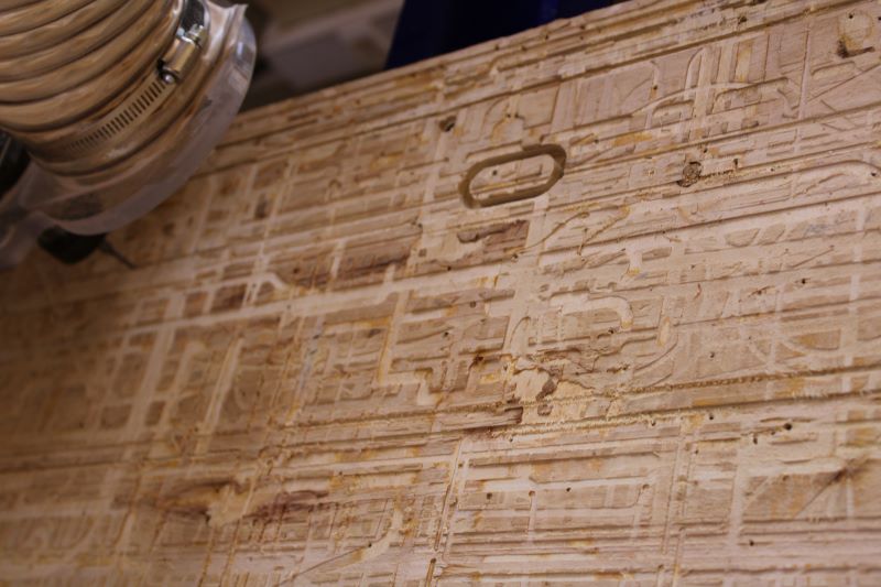
For our different tests we used a 3mm End Mill wick, and a pass depth of 02mm for the engraved "Offset-clim" and "Raster clim", the "Conventional Rasyter" and the circles. And we used 0.3 for the Offset -conventional.
The level of finish of each test was without defect, despite that the configurations were quite different.
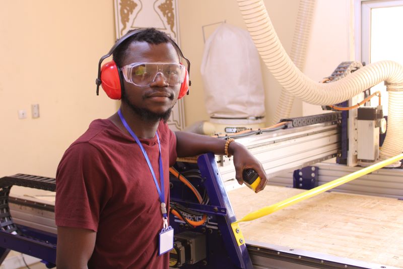
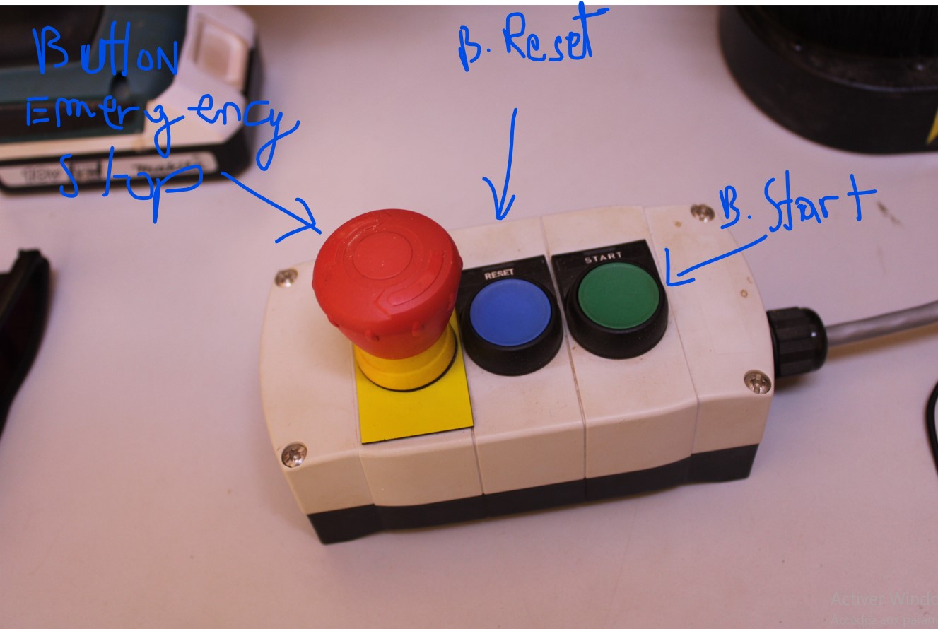
j.Safety instructions
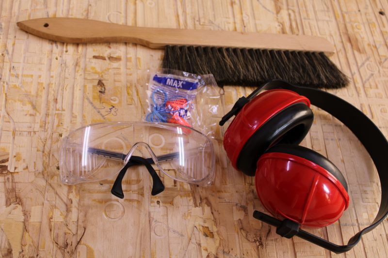
•Wear protective equipment because during operation of the machine it is very confusing.
•You should never wear jewelry or loose clothing..
•You should never try to switch off the machine while it is running.
•You should never try to put the spit in while it is spinning.
•Never leave the machine when it is not completely switched off.

l.Z-zero

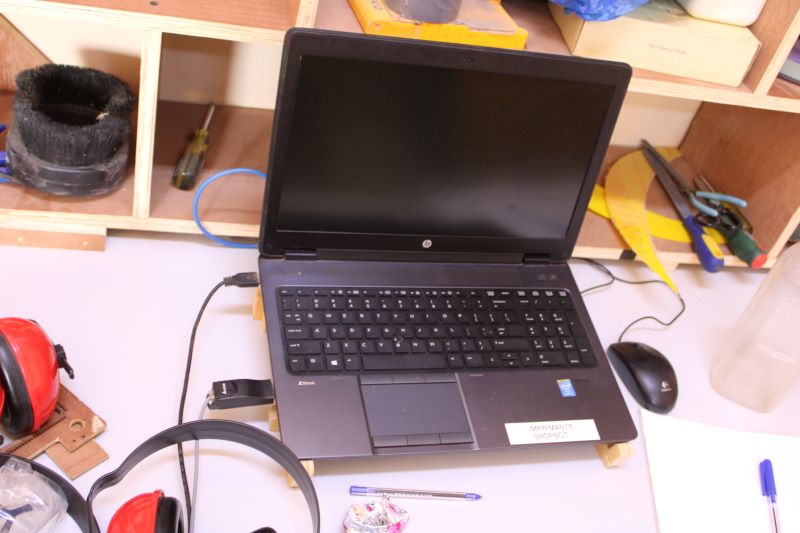
After changing the forest and then marking the zero point of the Z axis, we first open the shopbot software already installed on the computer, a red box appears, then we activate the control of the different axes of the machine with the box control yellow of which on the right we have the two horizontal buttons for the X axis and the two vertical ones for the Y axis and the two right buttons for the Z axis, then we exit by clicking on the exit button next we have deposited the touch plate below the drill so that we connect the mass by one of the threads of the bolts of the router and not on the bolt, then on the red box of the software we click on Z.0 then on OK. The router then makes a first contact between the drill and the touch plate then a second but much more slowly.
m.G-code import

After marking Z zero. We import our G-code plotters already recorded by clicking on "Cut part" first on the start button of the joystick to rotate the drill then on ok to start the engravings (this process is very important because if we press directly ok on the screen' the router will start to follow the traces without starting the motor which controls the rotation of the forest on itself). For the different engravings and cutouts, it works as follows:
First the router moves to find its starting point to edit on Aspire before starting to burn. Then to go to the cut the machine returns again to its starting point then begins the different cuts.
n.Conclusion on the tests
First the router moves to find its starting point to edit on Aspire before starting to burn. Then to go to the cut the machine returns again to its starting point then begins the different cuts
II.Indicidual Assignment

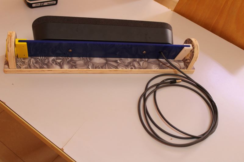
Pour mon projet final, Jai décidé de couper des supports pour nos baffles de conferance. Et ma découpe se fera dans un contreplaquer de 18mm.


b.Modelization
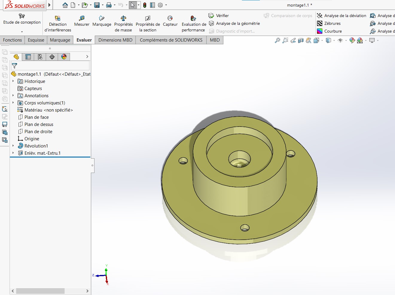
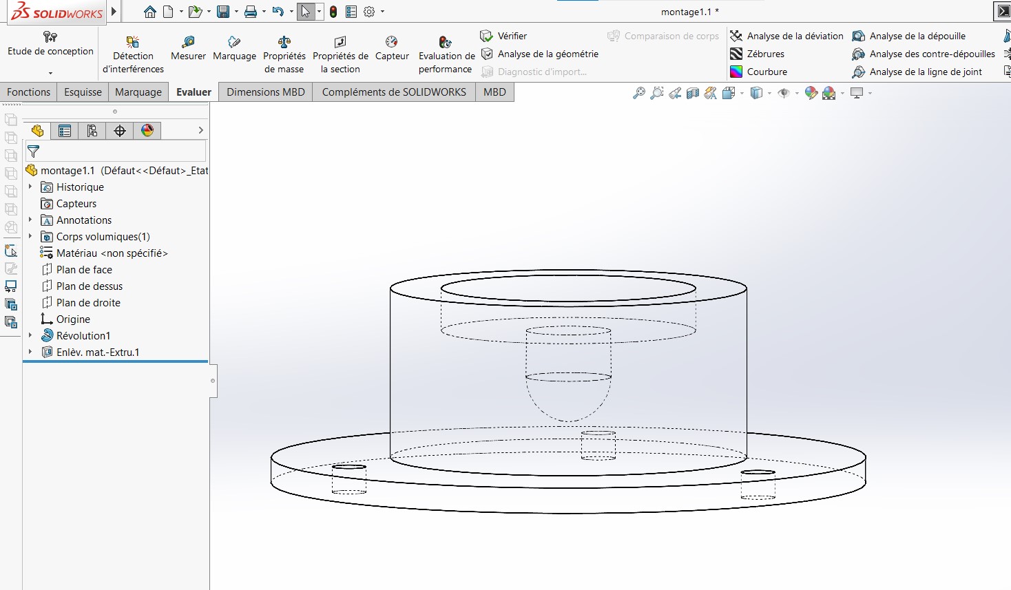
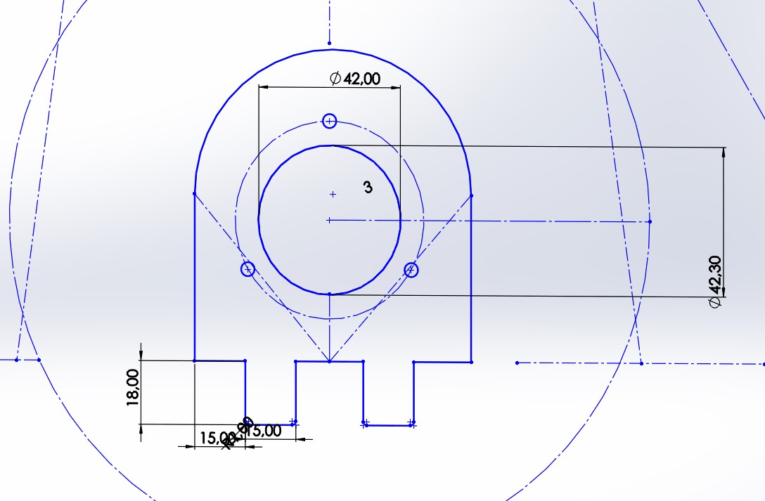
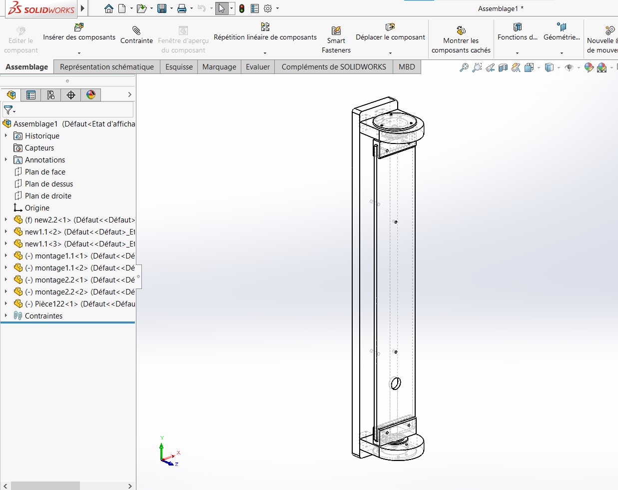
I have modeled a first model on solid woks equipped with a rotating part at both ends of the baffle that I will print with my 3D printer 3DWOX1 from Sindoh.


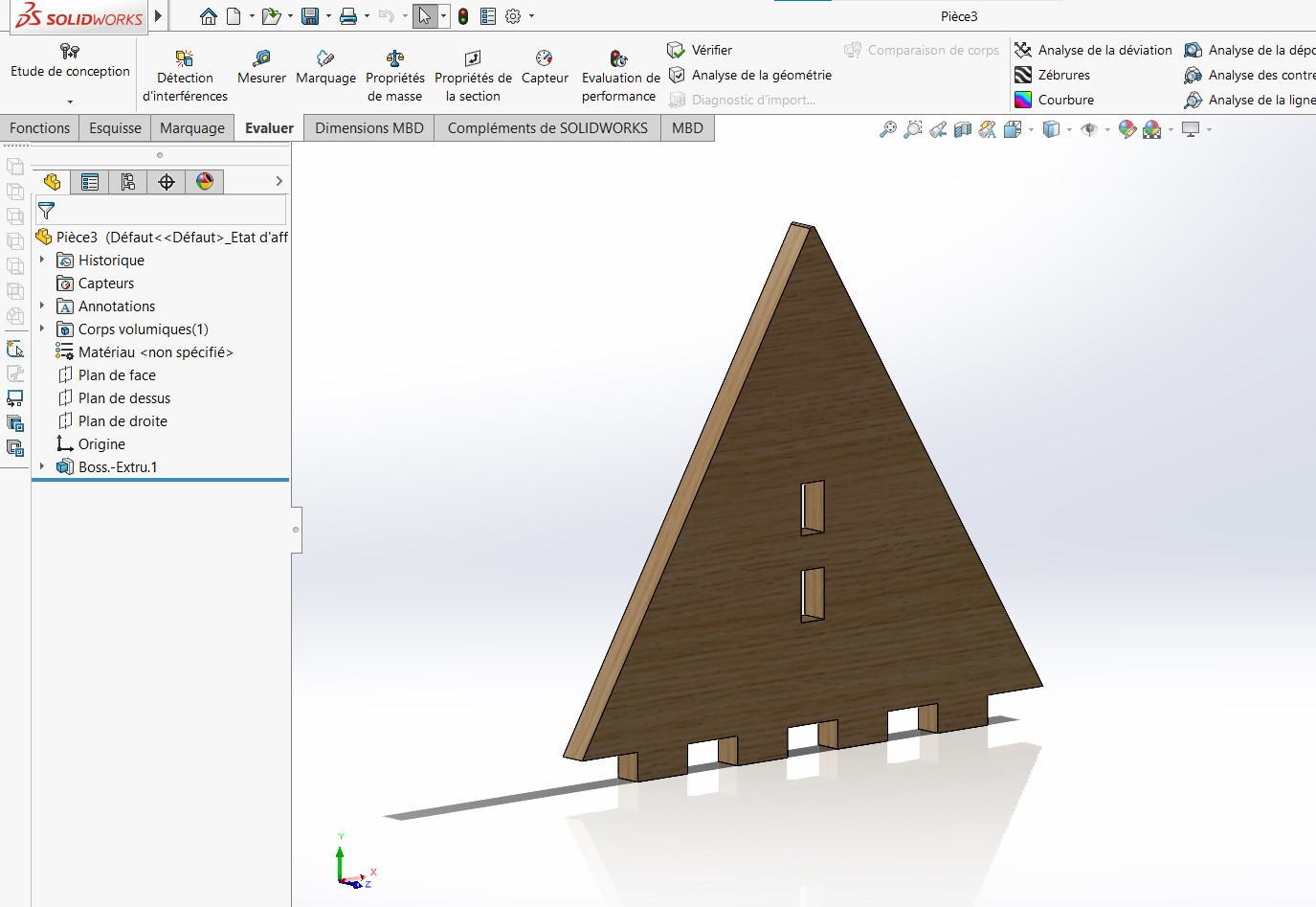


This rotary part is composed of two pieces which fit together with a 0.3mm clearance between the polished head and the cavity, to avoid direct contact between the two bodies, a 1mm clearance is also placed between these mobile bodies. For mounting my rotary part on the triangular piece provided for them and for assembly with the wall fixing part, I made rectangular holes inside my piece for wall fixing and added feet of the same dimensions to the triangular pieces for interlocking (I used the same dimensions because unlike 3D printing the pieces fit together well without even creating a game, but nevertheless I used chamfers at the level of the feet to facilitate mounting).
c.Problem encounter & rectification
Here is some image of my corrections on my first madel.
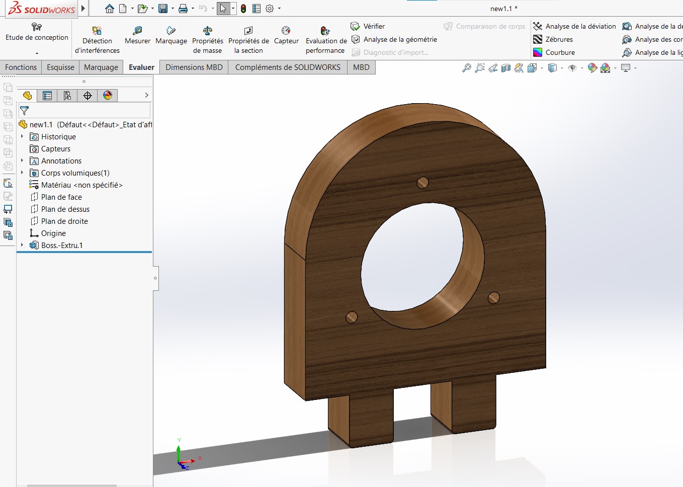
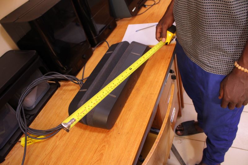
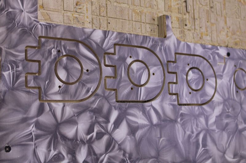
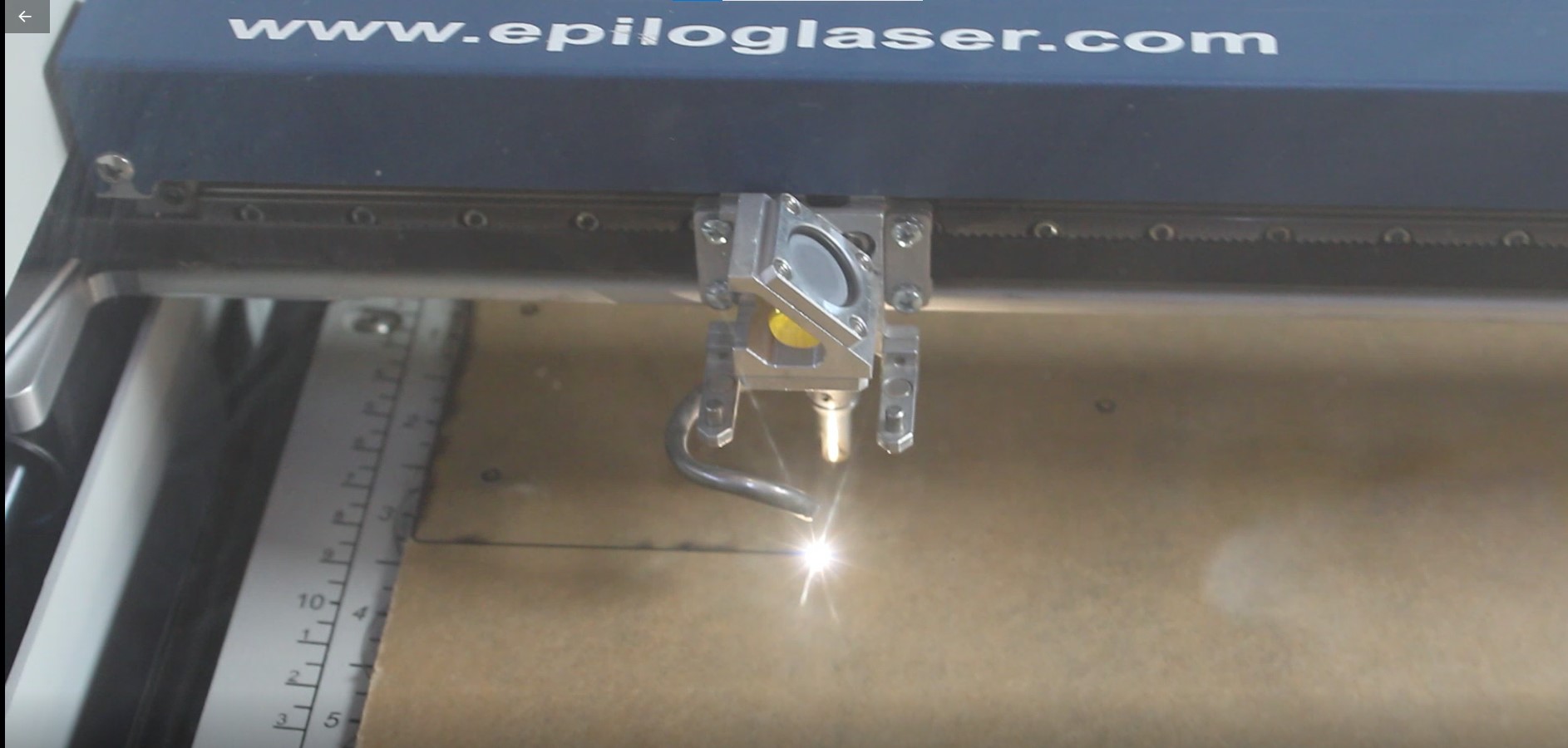
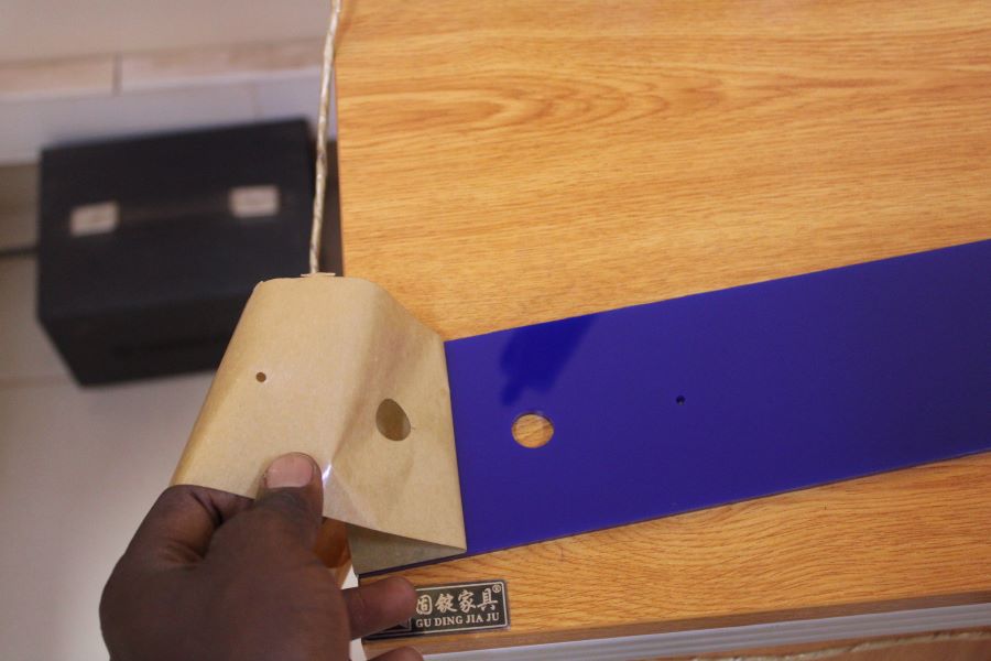
But the dimensions of the first model did not fit into the space reserved to place my baffle so I had to design another model even smaller and with fewer feet than the previous one. And since the first model was long and for a matter of aesthetics, I also took the opportunity to resize my 3D printed part so that its size did not exceed the thickness of the plywood too much during assembly. I also made a hole in the middle of my piece to mount my printed pieces. I also cut with an aser a 6mm plexiglass from which inside I made 4mm diameter holes to target my spiker and a 10mm diameter hole to pass the connection cable of the spikers.
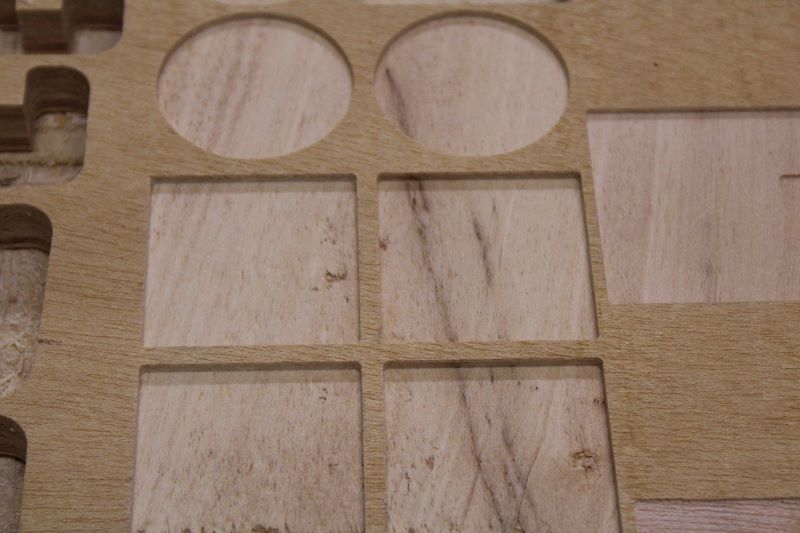
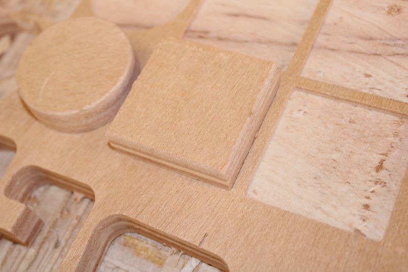
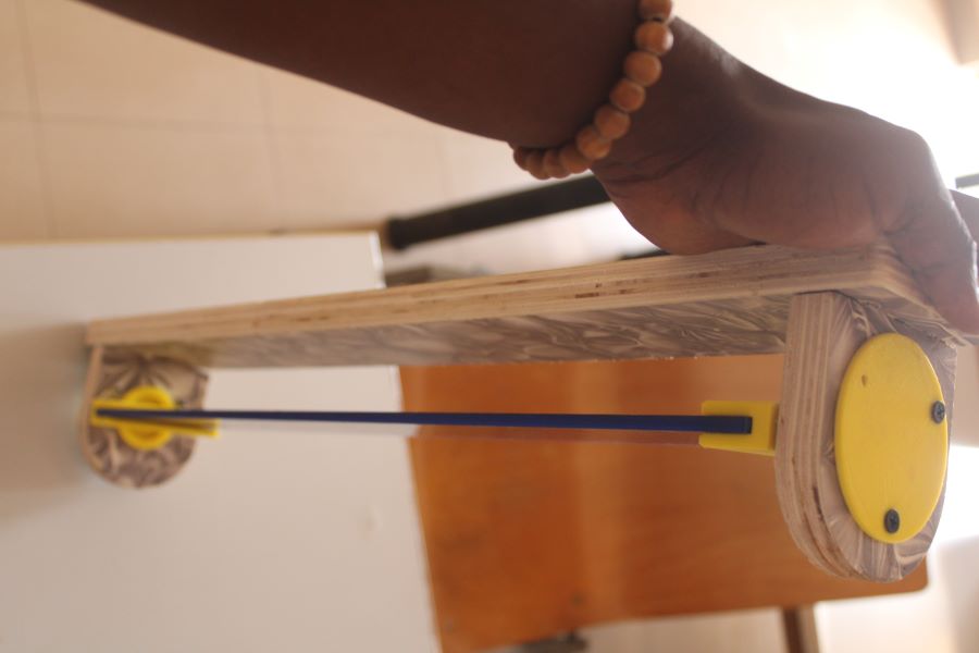
d.My cutouts & prints
Here is some image of My cuts and printing.


But the dimensions of the first model did not fit into the space reserved to place my baffle so I had to design another model even smaller and with fewer feet than the previous one. And since the first model was long and for a matter of aesthetics, I also took the opportunity to resize my 3D printed part so that its size did not exceed the thickness of the plywood too much during assembly. I also made a hole in the middle of my piece to mount my printed pieces. I also cut with an Aser a 6mm plexiglass with the MINI Epilog from where inside I made 4mm diameter holes to aim my baffle and a 10mm diameter hole to pass the connection cable of the speakers.
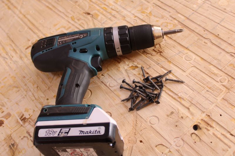
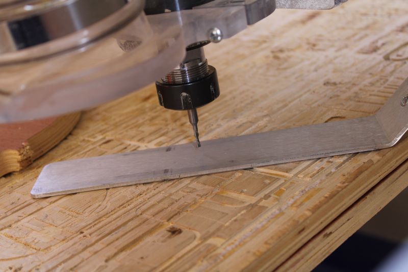
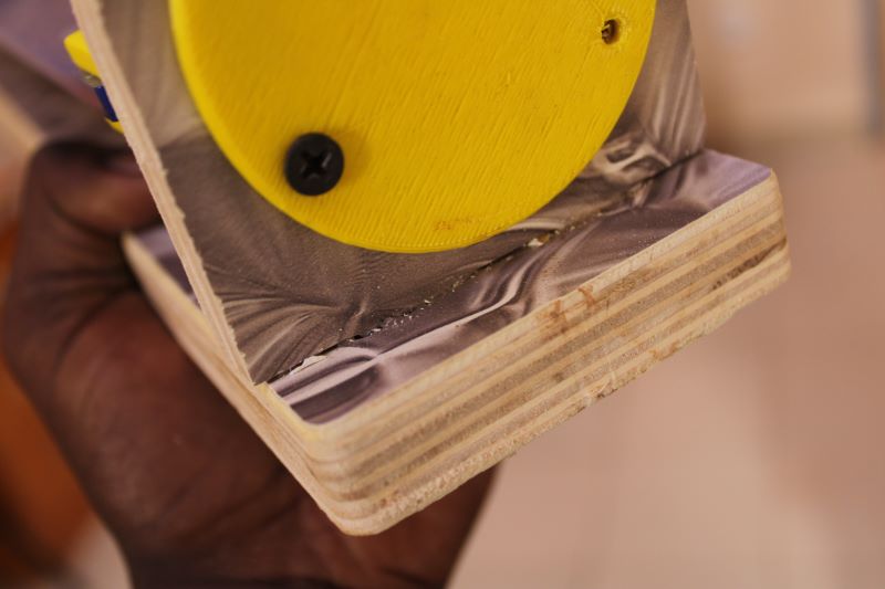
e.Accidents meet
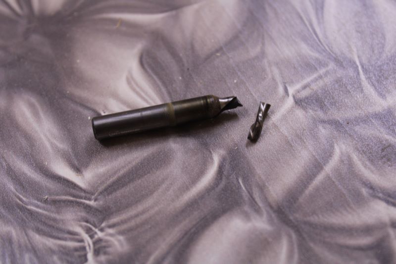
During the cutting I broke my drill bit with one of the fixing screws that I placed to better press the deformed counterplate to the sacrificial layer.
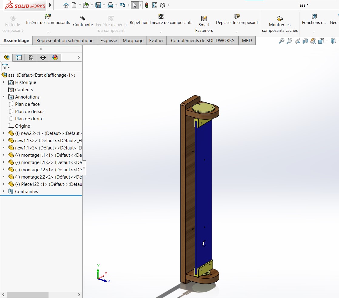
f.Mounts

First I assemble with a mallet and glue my fixing piece to the wall and my support for my 3D printed parts.
Then I screw my first rotary parts to the two supports and then with my second rotary parts.
Then I mount my main piece cut with the Aser.