Week Three
Computer-aided designe
• Model (raster, vector, 2D, 3D, render, animate, simulate, ...) a possible final project, compress your images and videos, and post it on your class page.
New software used this week:
3D design software
•1. SolidWorks
•2. FreeCAD
2D design software
CorelDraw
I.FreeCAD : Logiciel de conception 3D
FreeCAD is a general-purpose 3D parametric computer-aided design (CAD) modeler, it is intended for the design of mechanical engineering products, but is also used in engineering, such as architecture or electrical engineering . FreeCAD is free and open source software.
a.Modelization
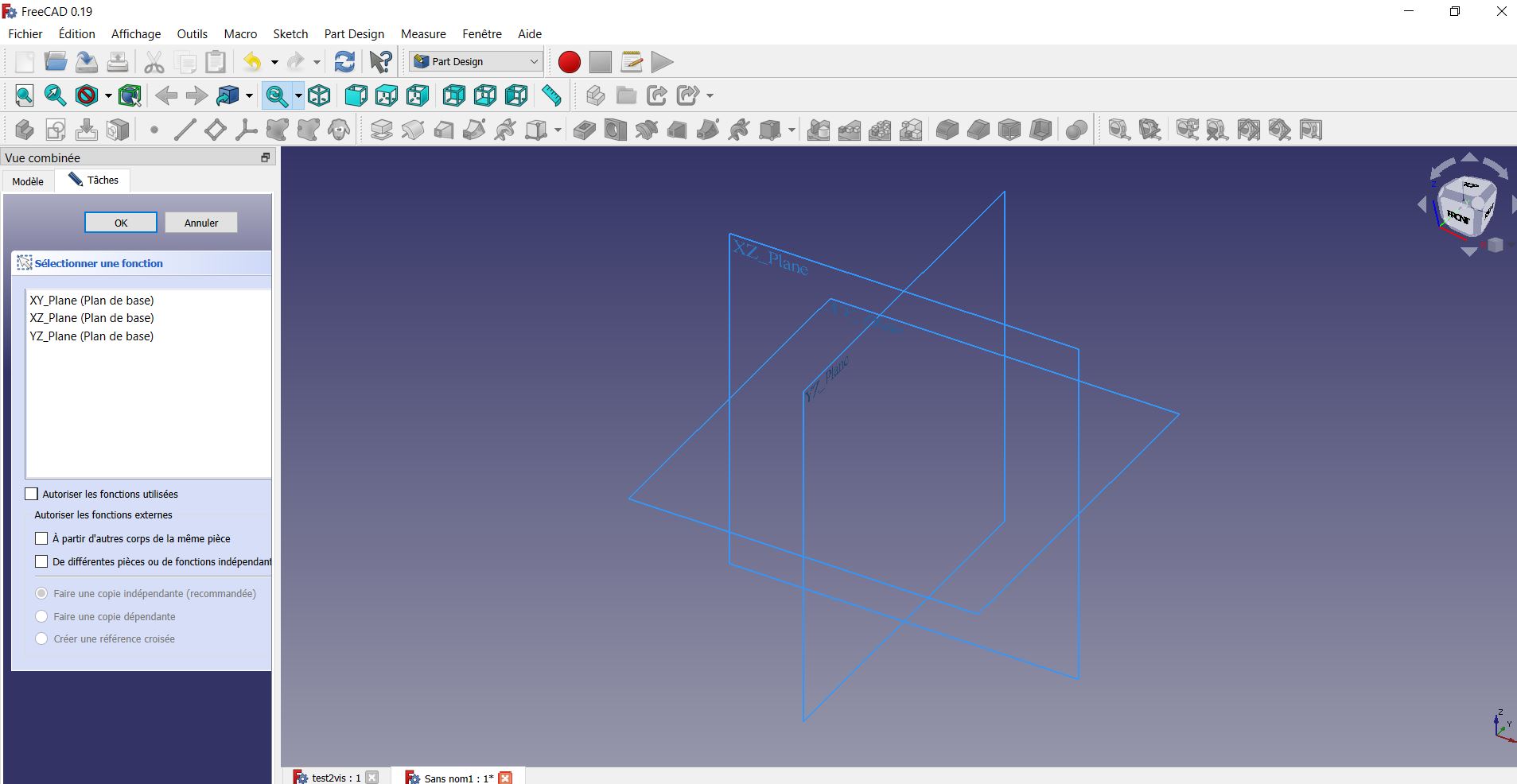
First of all, to draw a sketch, you need to click - Start: Sketch option in the toolbar at the top as shown in the picture. When you select the Sketch option, it asks you to select one of three planes to draw a sketch. Once the plane is selected, we can use the drawing and constraints toolbar at the top to draw objects such as line, rectangle, circle, etc. Actually this is my first time using this software so I looked at some tutorials and so I wanted to make some basic piece to train myself to better understand how it works.
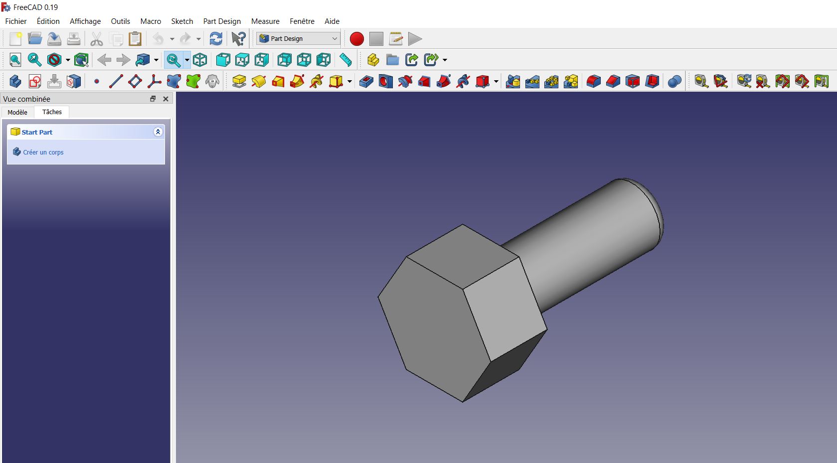
So I first sketched a polygon and then I extruded this polygon by selecting the Part Design module at the top. The sketch must have a body to perform operations such as extruding, cutting, sweeping, etc. There is Add Body button on the left as shown. Then I selected one of the faces of my polygon, after extrusion on which I made a circle, I added depth for the extrusion to create a cylinder like the image below noted.
b.My first test
To work with the other functions I redid another sketch by clicking on new then on sketch I gave the shape of my object then added the vertical and horizontal constraint dimensions. Then I made a construction line to be able to use the revolve tool, after I went out of my sketch then I selected my sketch and applied the revolve function and it immediately took the XY axis.
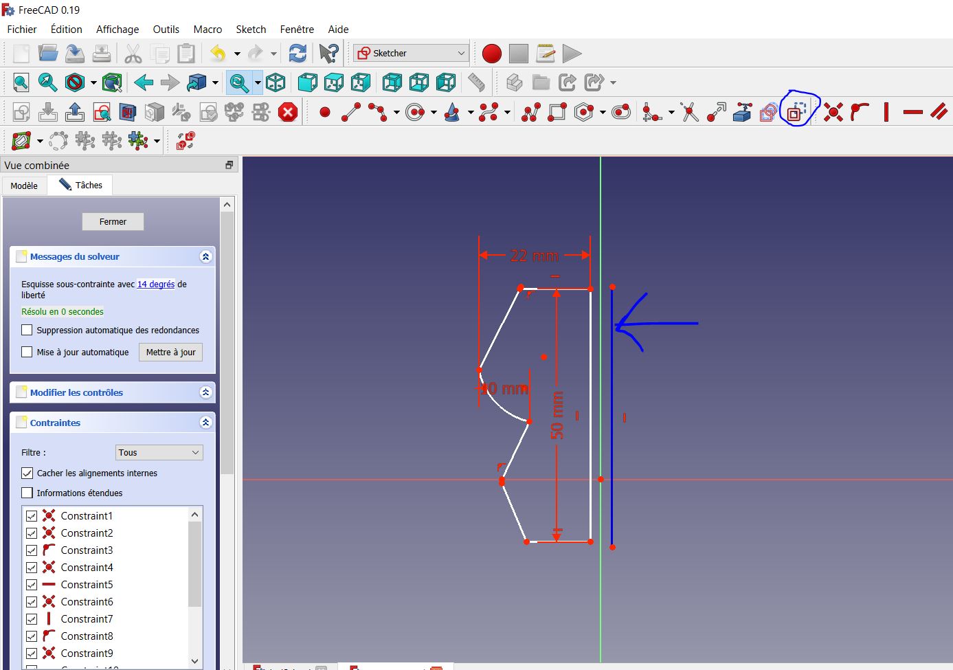
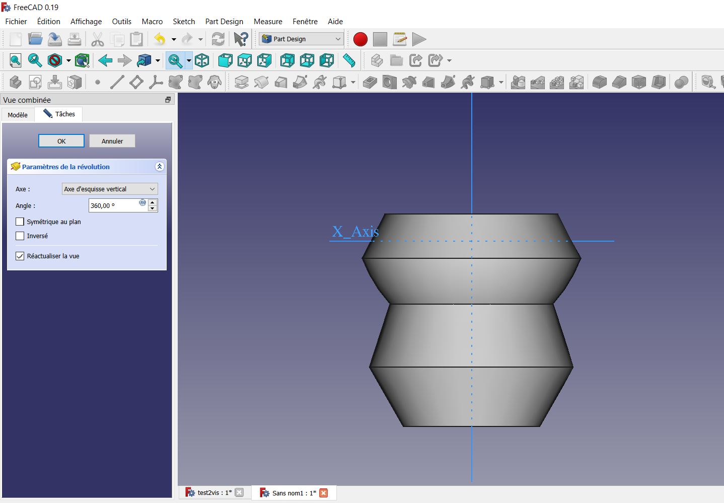
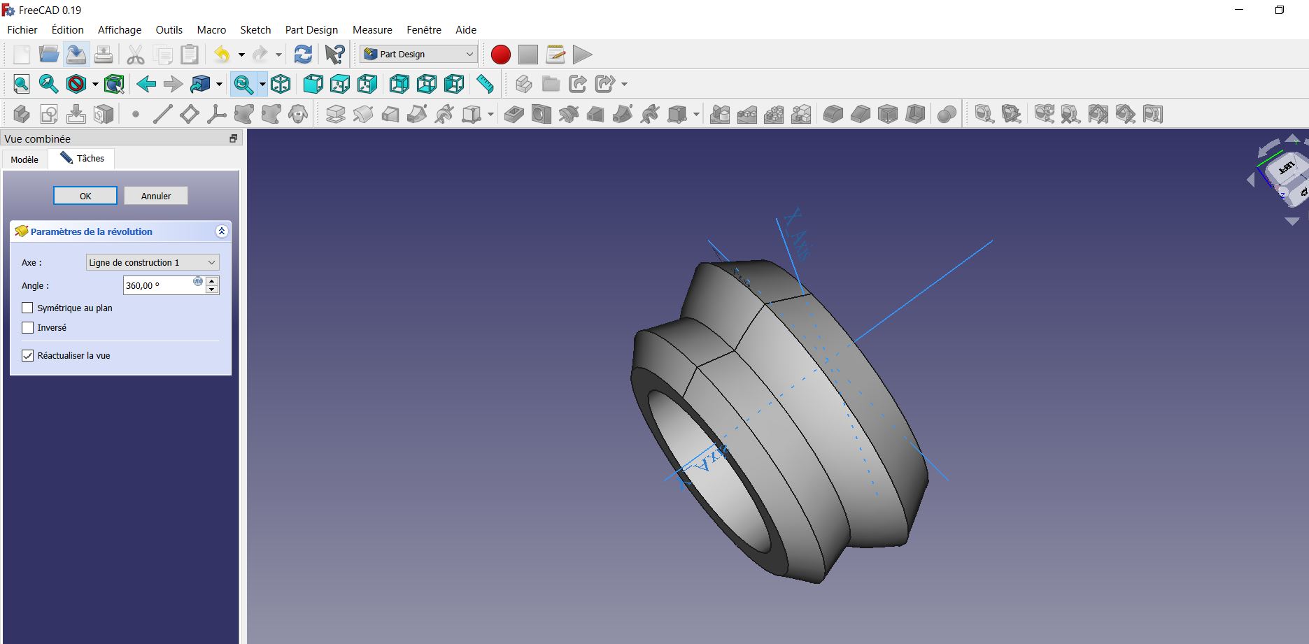
revolution with the construction line
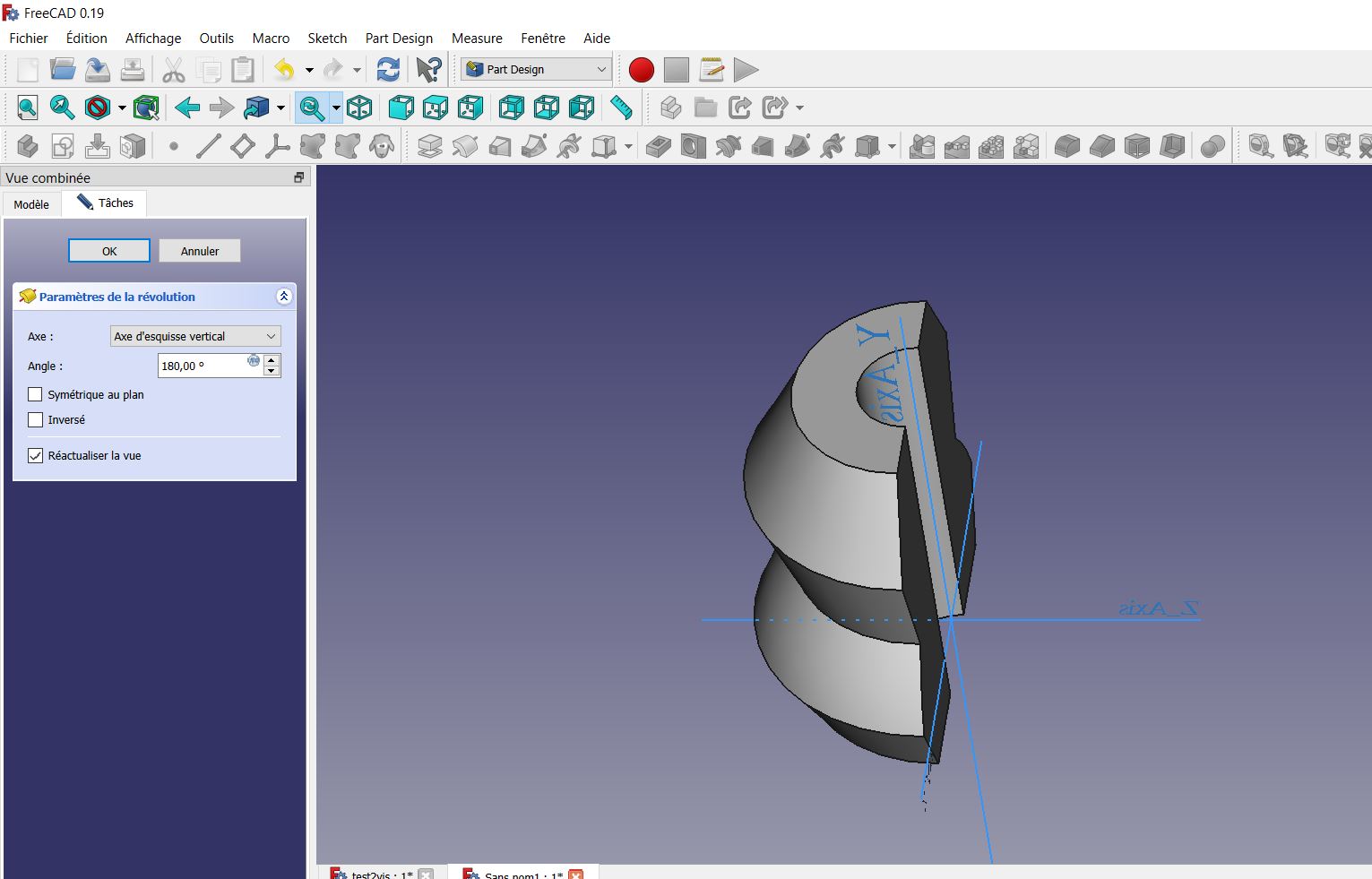
Then with the degree of revolution I cut my object in half using 180degree instead of 360 and selecting from the menu the axis of revolutions my line continues this has modified as I expected the thickness of my object then that it was much further away from the axis of revolution by default.
II.SOLIDWORKS: 3D design software
SolidWorks is a computer-aided design (CAD) and computer-aided engineering (CAE) solid modeling software provided by Dassault Systèmes, which primarily runs on Microsoft Windows. Although it is possible to run SolidWorks on an Intel Mac with Windows installed, the application developer advises against this. SolidWorks does not support macOS.
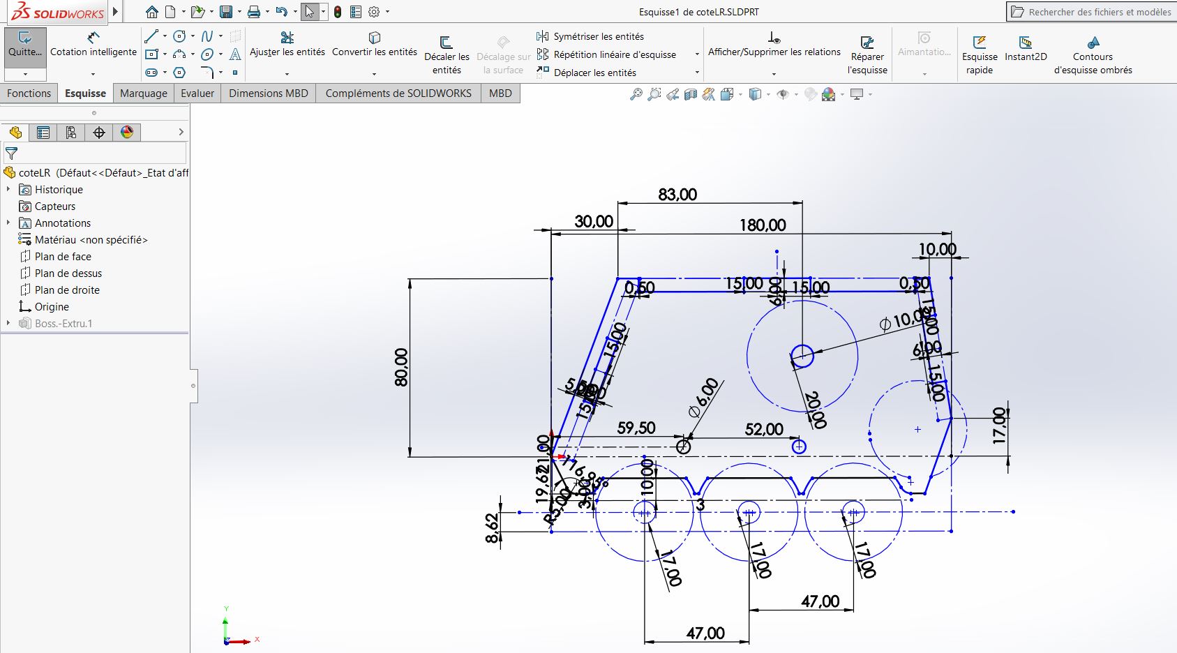
First of all, to draw a sketch, you have to open the Sketch option in the toolbar at the top. When you select the Sketch option, select one of three planes to draw a sketch. Once the plane is selected, we can use the drawing toolbar at the top to draw objects such as lines, rectangles, circles, curves, and other Polygonal shapes. For this week I wanted to work on my final Project for this mission. Knowing that my final project is a robot in the form of a car, so I sketched each part for assembly.
Then I made the sketch of my different parts that I will use to assemble later.
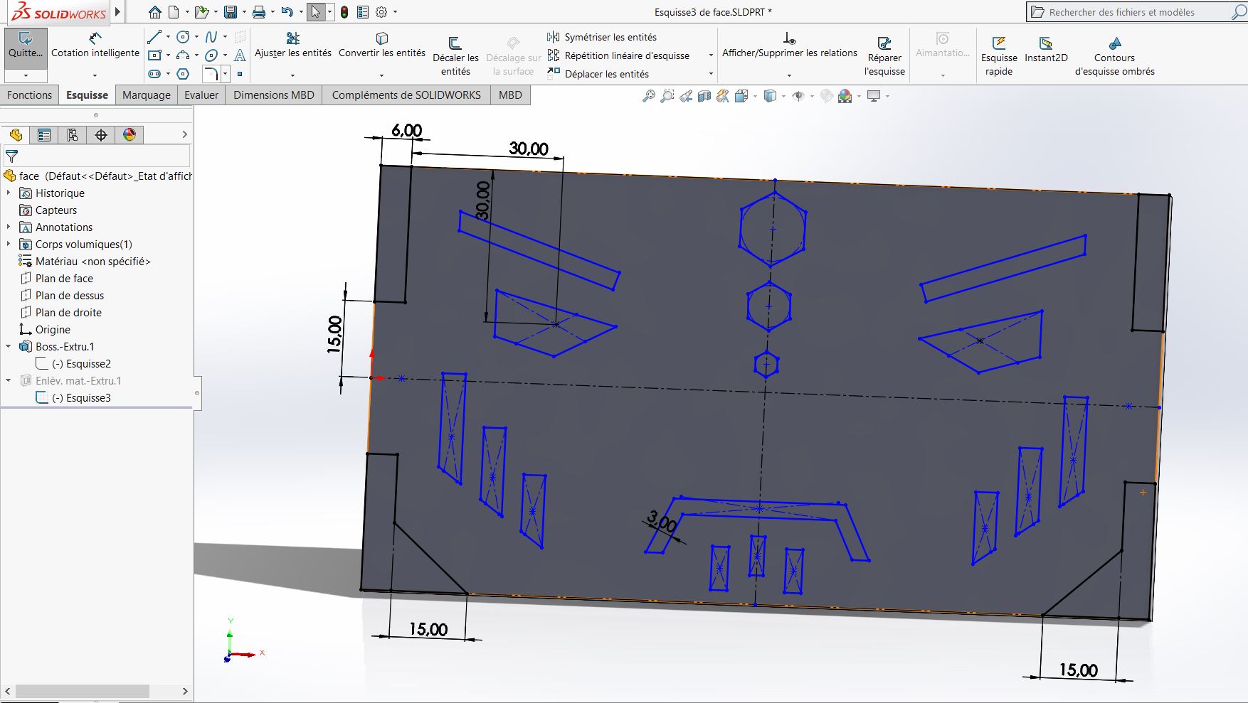
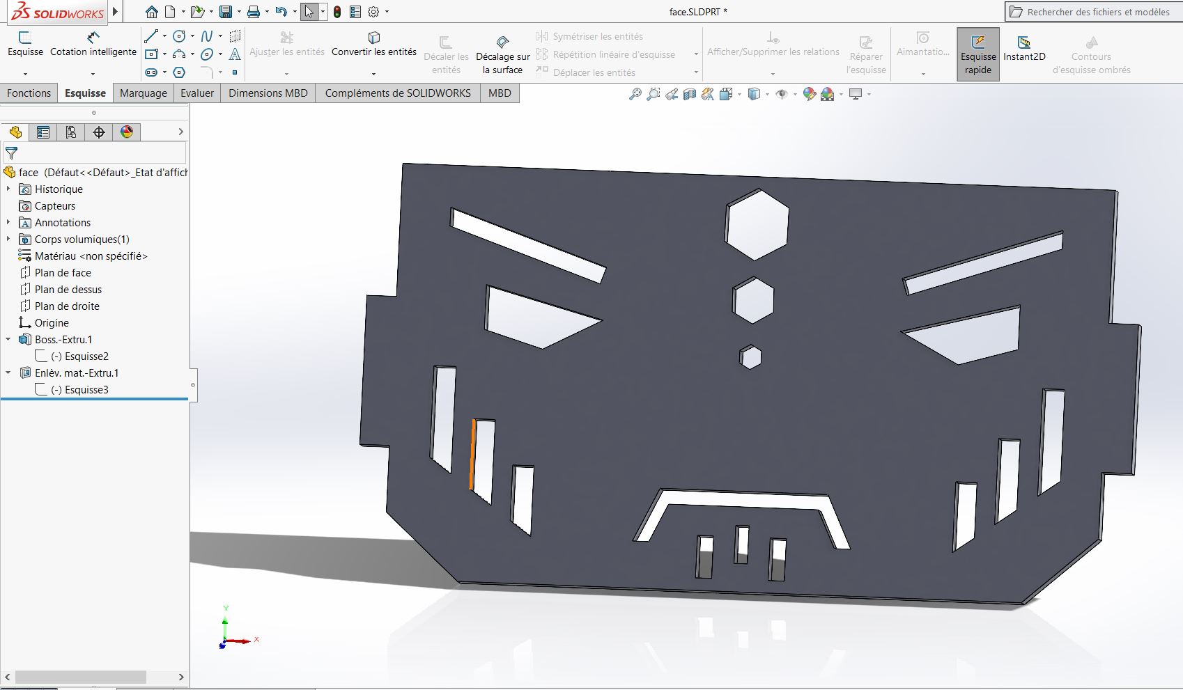
For the sketch of my robot's face, I used a rectangle on a right view plane, then I made the boss/base extrude the rectangle using the extrude tool. Then I click on one of the faces obtained on which I make another sketch I draw the eyes the lines on the face and some hexagon thanks to the polygon tool after having finished my various sketches I go to the function menu or I uses the extruded material removal tool. I save in my create folder in the front panel named final Project. In addition, all the parts that will have to be part of my assembly will all be in this same folder, if the assembly will not be possible.
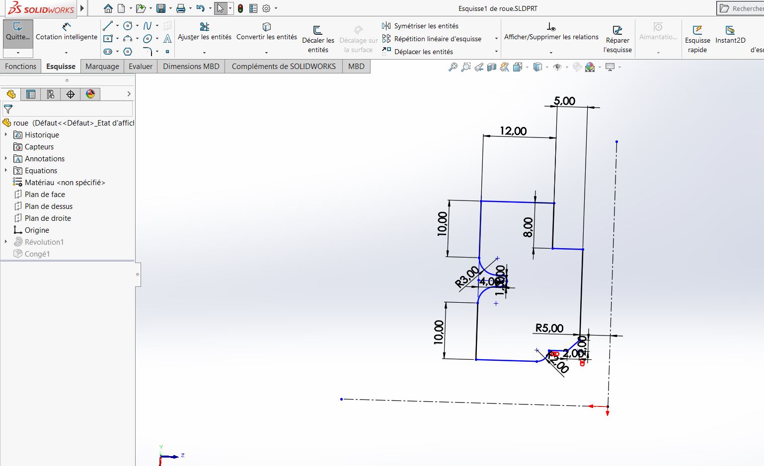
For the wheels I first choose a plane on which I make my sketch and with a construction line that I place to the left of my sketch, then I go to the function menu or I make a revolution using my construction line as axis of revolution. I record in my final Project too.
Coté laterale
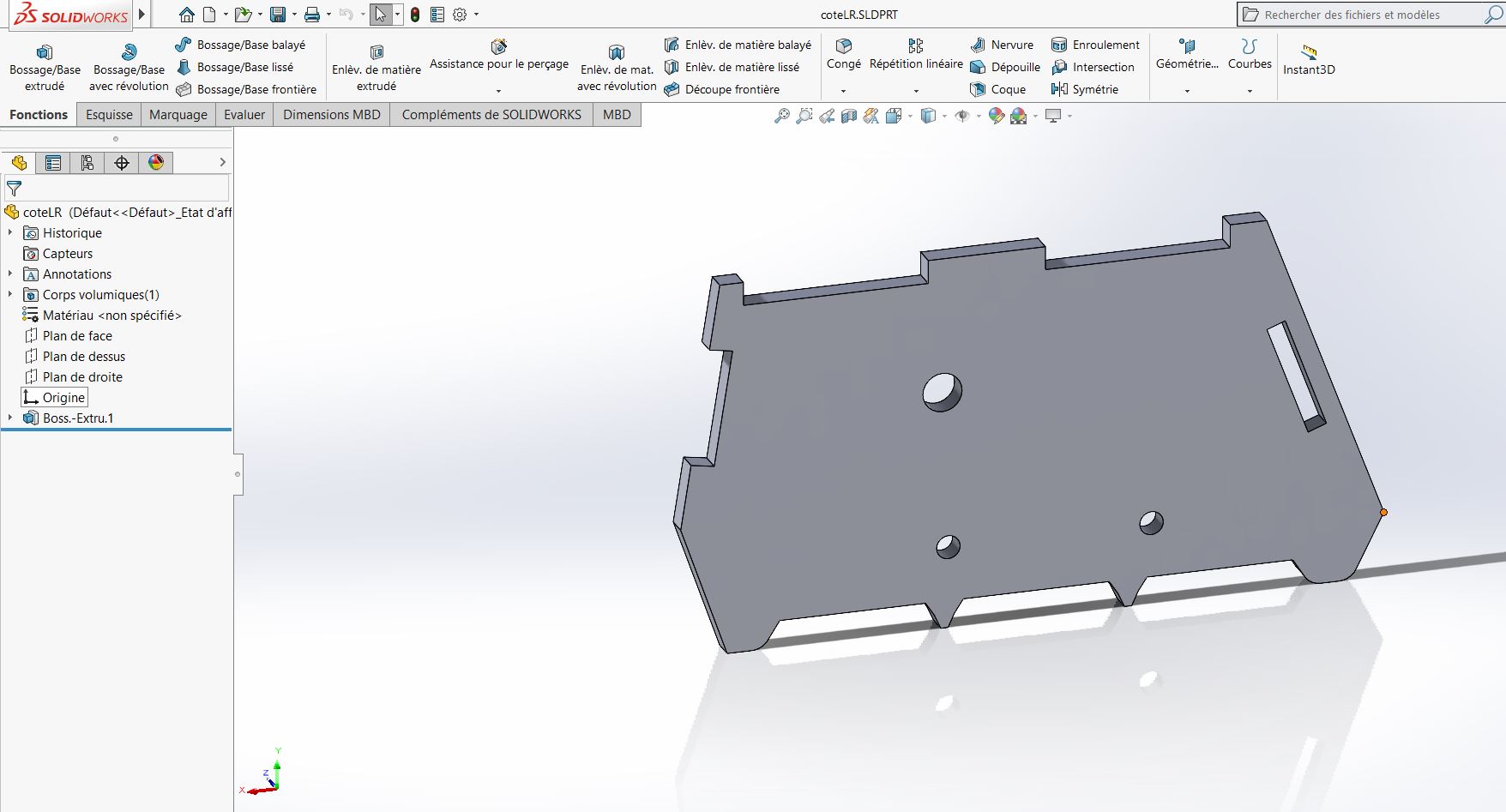
The left and right parts of my robot are identical so I sketch a single one and then in the function menu I make an extruded boss.
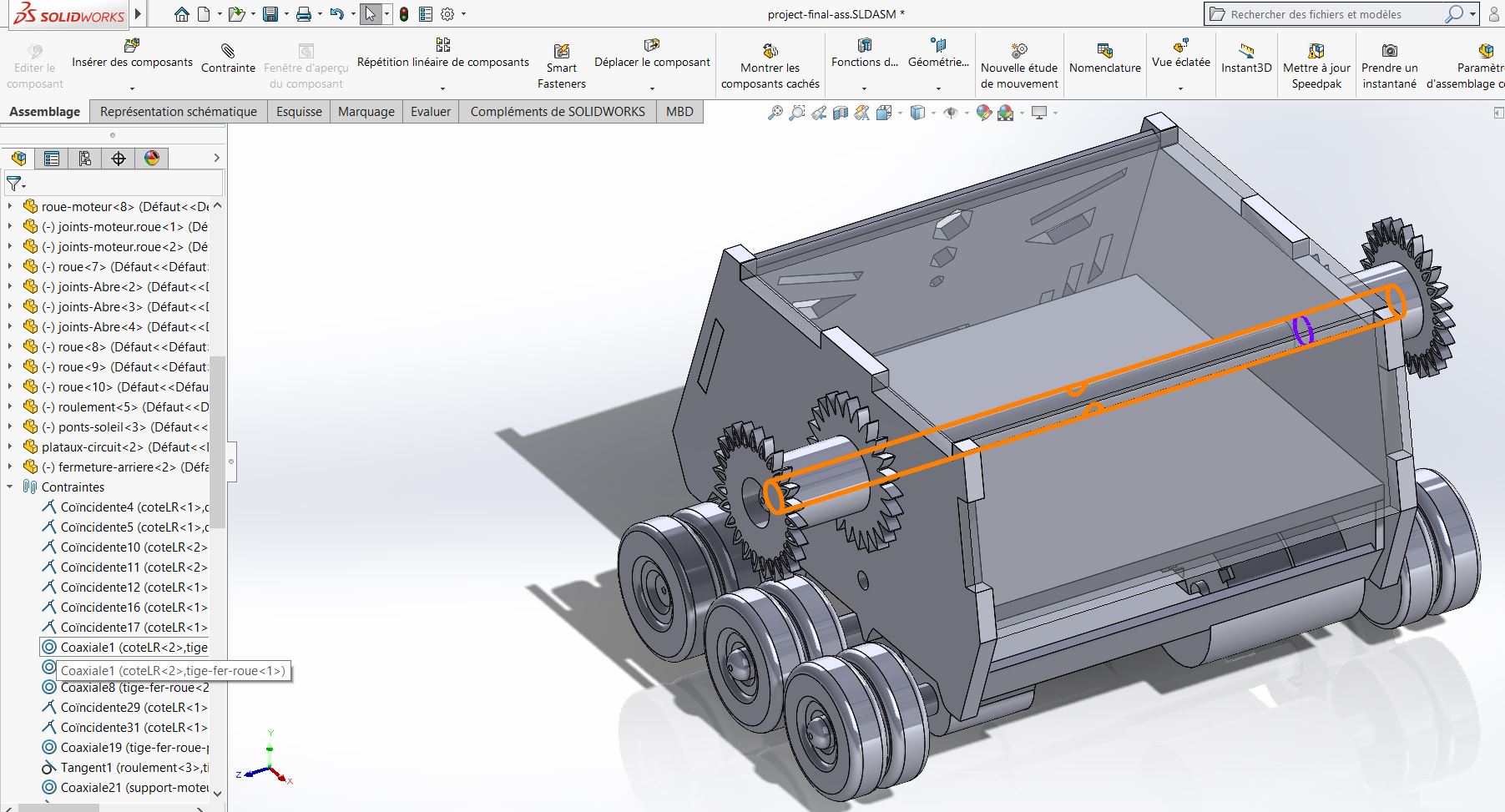
After having finished the design of all my parts, I direct my pointer to the arrow located next to the solidworks logo below I click on create an assembly from the part. This brings me to a new window first I place my first part (here no need to create a plan to do the assembly) then at the top in the assembly menu I click on insert components. At the bottom I go to the Final Project folder then I choose my components to insert I do this one by one. To assemble, you must first choose, using our mouse pointer, the side of the part that must be assembled. By clicking we will see a tool called constraint symbolize by a paperclip. I click on the top and it offers me the different constraint option that can be applied. We put parallel, coincidence, block (when you want it to stay in a place where you placed it), distance, tangent and etc.
Assembly with Solidworks
All its parameters will be used in my assembly to create my constraint. For example, I will use the Coaxial constraint to assemble my wheels and bearings around my axial shaft and the coincidence constraint for the assembly of my side dimensions of my robot.
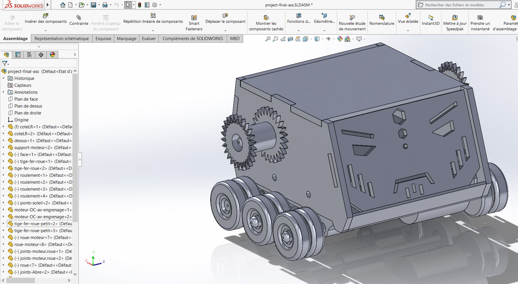
Thanks also to the small menu located just at the bottom of the toolbar I have a tool called Display Style which allows me to see inside the assembly and the orientation tool allows me as in the design of a piece to orient my piece to have a better view (but hey, I use the middle button of my mouse a lot more to do my orientation.)
Each time an assembly is made, you can see on the left the different parts used for the assembly and just below the parts are the constraints to be used for the assembly.
III.CorelDRAW:2D design software
CorelDRAW is a graphics suite developed by software publisher Corel. Originally it was CorelDRAW vector drawing software. Over time, other software such as Corel PhotoPaint and Corel R.A.V.E were added and the software became a graphics suite.
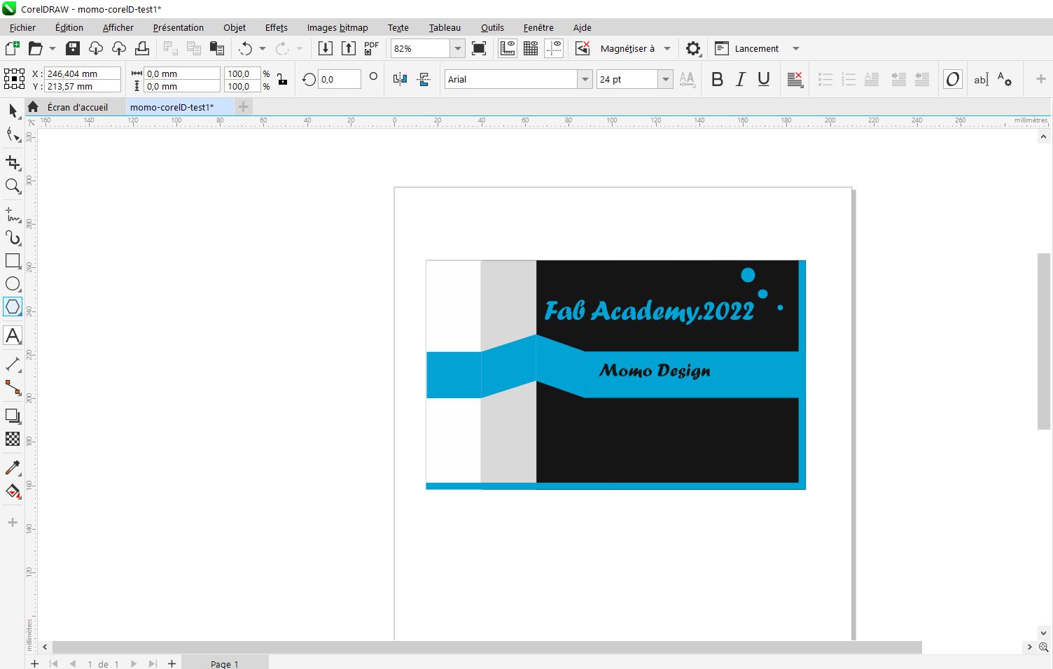
My Design
For this week I decided to familiarize myself with this software by creating a business card.
To start I had to download it from the GET INTO PC site. And I had to follow a video for the installation which was rather very long.
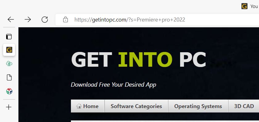
Here is the download link here
B. Test
the images below indicate the step followed for the design of my card

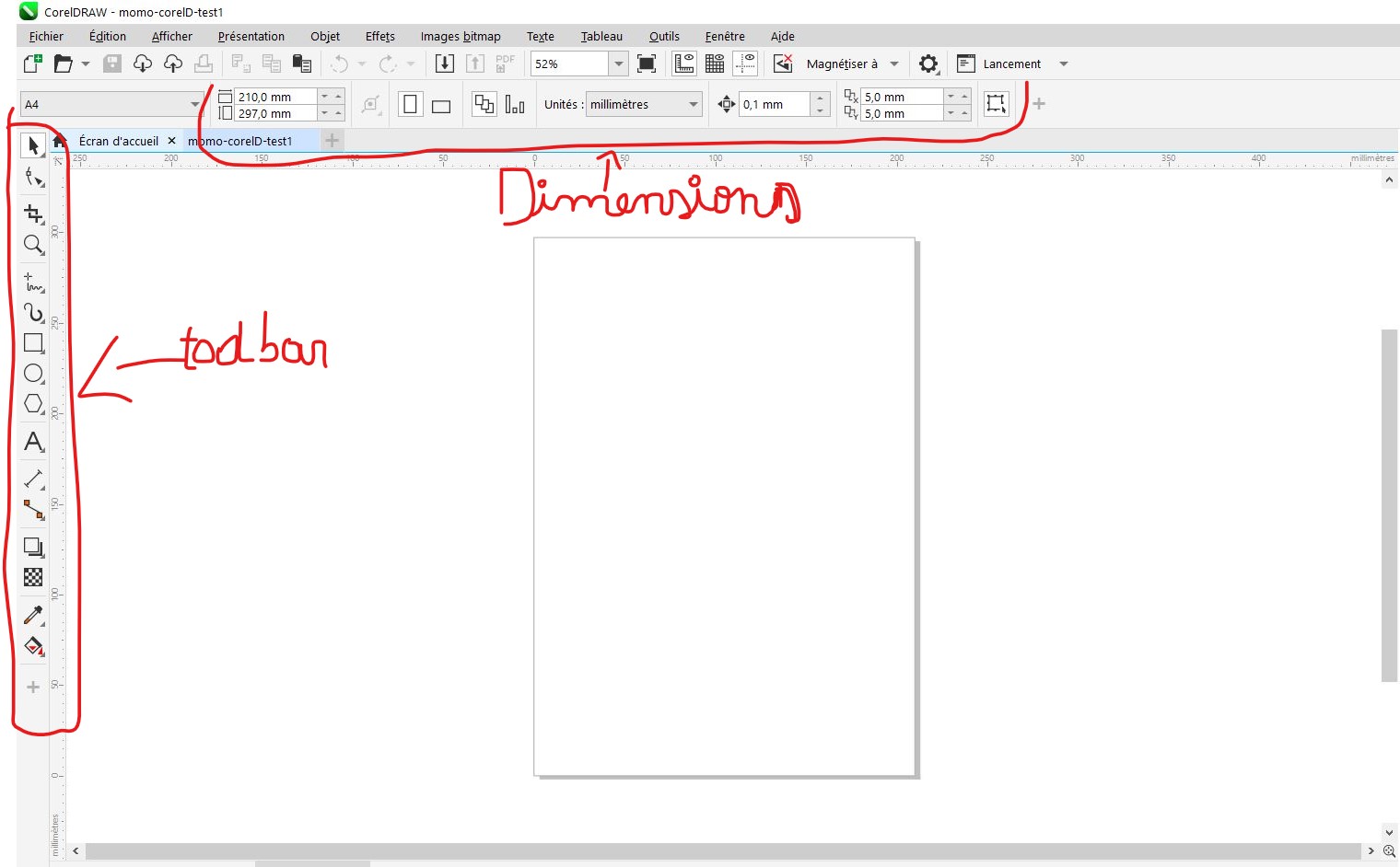
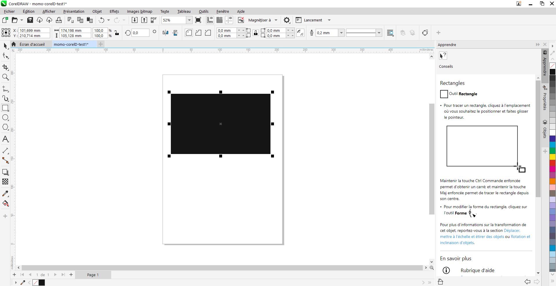
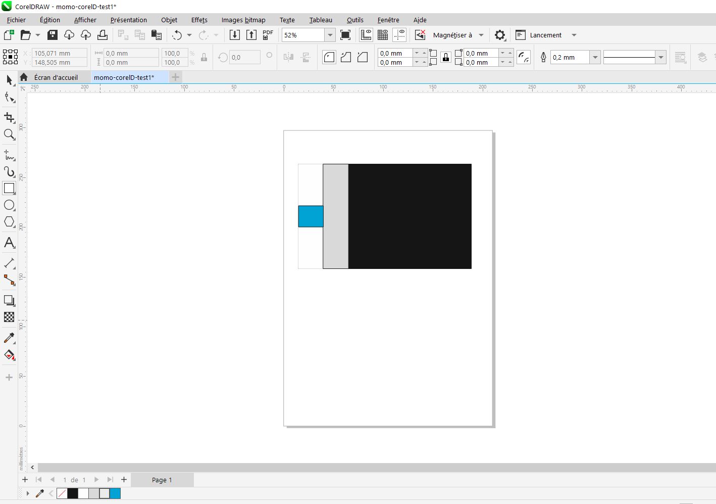
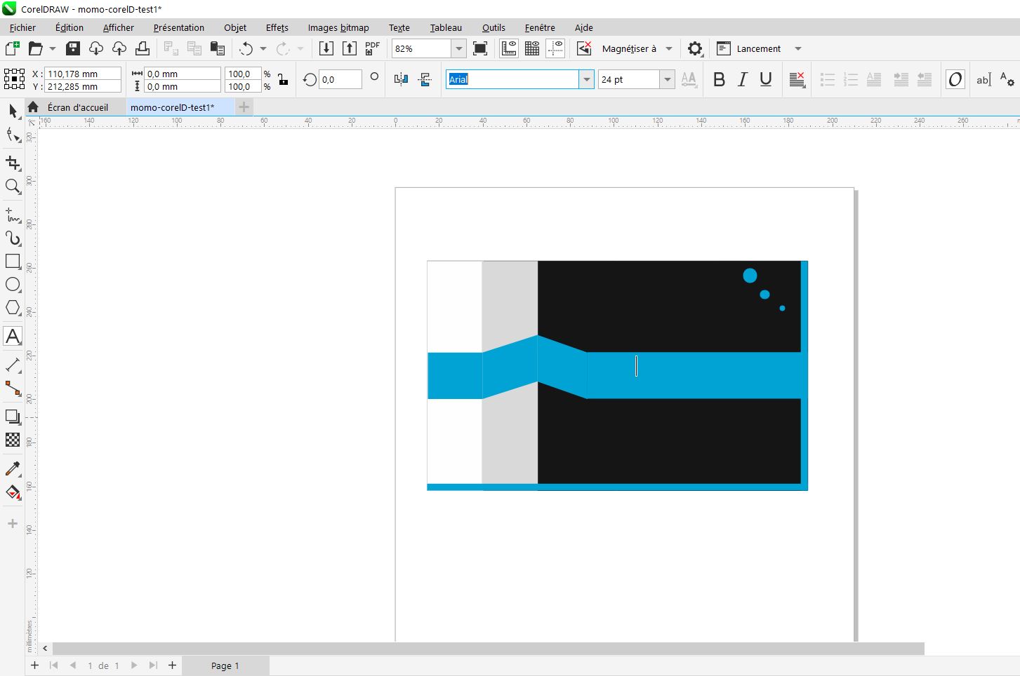
First before starting, I click on new document then a marker appears and there, you have to create the workspace I chose an A4 sheet with the vertical position. then I press ok, a new page appears with the toolbar on the left and colors on the right and at the top we have the different dimensions of our A4 sheet and also the Font for the letters. I start by creating a rectangle that I but in black then I add another rectangle that I but in white (to choose the colors you need a left click on your chosen color for the interrier color and a right click for the outline colors of your form). Then I select my white rectangle and I duplicate it by pressing Control D on the keyboard. Then I position it next to the first one I change the color so that it is a little darker then I eliminate the contours by clicking on the white carer at the top with the red line in the middle to make them disappear. I add another small carer that I put in blue then I duplicate this one. After I click twice on it to modify the shape of my second square I then duplicate it and with my arrow I position it symmetrically to the previous one. After I create another much longer blue strip, and above I add small circles in blue. Then with I use I write on my card only blue and in black after I save it in my corel file that I created.
Final product