Week Seven
Electronic design
For this week, I'm going to learn more about the equipment we have in the lab to better understand what's going on inside a PCB. I will also design a board of HELLO-WORLD and upload some code to it to see if it works.
I.Group Assignment
The purpose of the group assignment is to check the equipment available in the laboratory to see what is happening in a printed circuit board and therefore For this we will need the following measuring equipment:
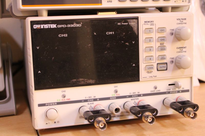
A multimeter, an oscilloscope, a Low Frequency Generator (GBF) and a power supply generator.
a.Test 1
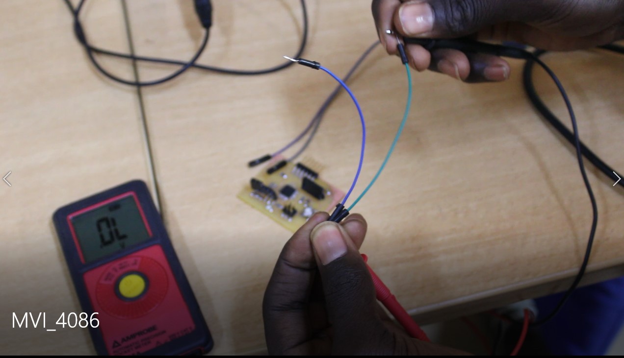
The multimeter used here is to check the voltage and current, the electrical continuity of our printed circuit.

To take the measurements we connected the multimeter in parallel with the card and measured the voltage between our two GND pins and the VCC of the card. The values obtained for the voltage with our multimeter is 5.025V which is good. And for the intensity we measured about 1125mA.
During our tests we noticed a continuity problem with one of our wires and we also tested and changed it.
b.Test2
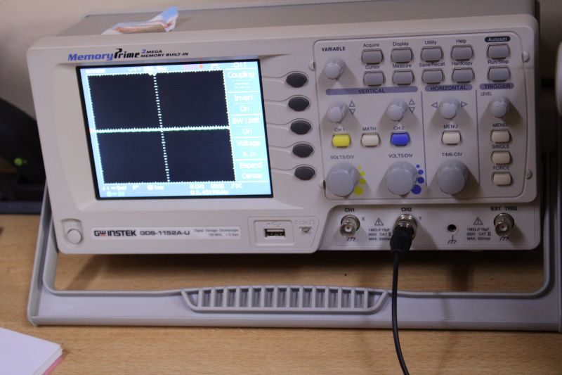
l'oscilloscope
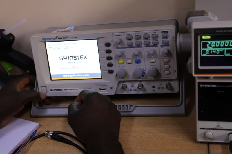
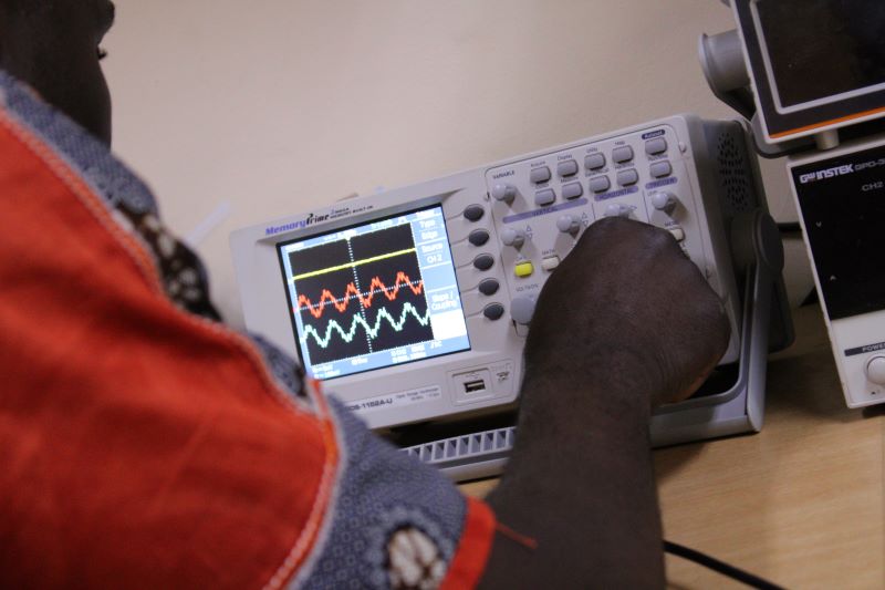
The GW INSTINK GDS-1152A-U oscilloscope and like all other oscilloscopes, are devices for viewing the electrical signal in our printed circuit. It is a measuring device that presents an electrical signal in the form of a curve, which is actually most often a variation of voltage as a function of time.
>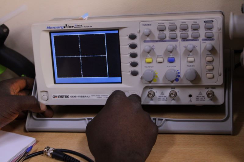
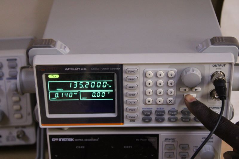
It proceeds two inputs (channel) which are CH1 and CH2 so that we can view two signals at the same time. There are also certain oscilloscopes with four ABCD inputs. But ours with two inputs will do. We can also take screenshots by pressing the stop button and get a clear picture of what is happening because the signals emitted are unstable on the screen. The devices that accompany our oscilloscope are: A voltage generator and a low frequency generator (GBF). The voltage and current generator here will allow us here to find the voltage and the current which will cross our circuit and the GBF will indicate its frequency to us.
Curve observation test on our oscilloscope and frequency measurement on the ATMega328P-AU board
We plugged in the board's CON-06-FTDI-SDM-HEARDER with an ISP female cable connected to the oscilloscope. We first start by bringing up the strip of channel 2 which was at the bottom First we start by turning on our oscilloscope Then we turn the cursor of the vertical movements to make the two bands appear on the screen, we then eliminate the band that we do not want by deactivating it thanks to this button.
After choosing our band, we start by setting the caliber and the corresponding time base, which here is:
Range: 100mV
Timebase: 50µs
To do this we used the TIME/DIVE sliders for the time base and VOLTS/DIV for the caliber
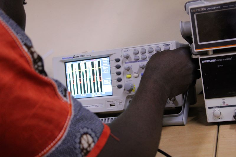
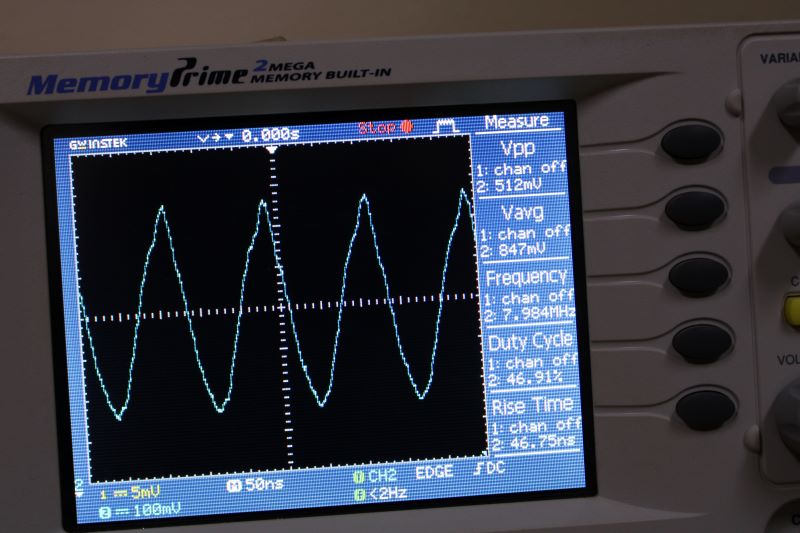
To stabilize our strip, we first go to the MENU button above the timebase slider. Then with the button to choose the channels that we synchronize with our channel. And then with the LEVEL slider we bring back our trigger threshold. After having to synchronize the band so that our signal is stable, we obtained a frequency of 7.984MHz which we can read on the screen of the oscilloscope
II.Individual Assignment
a.My HELLO-WORLD card.
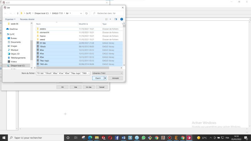
For the design of my hello world card I use Eagle 7.7.0 software.It is a software that I was advised for the design of my pcb
I find this software rather very practical, especially if you are already a user of one of the AUTODESK products such as AUTOCARD for example, its menu and its functions are almost similar. You already have the main tools such as Add, delete, move, mirror, rotate, copy and many more
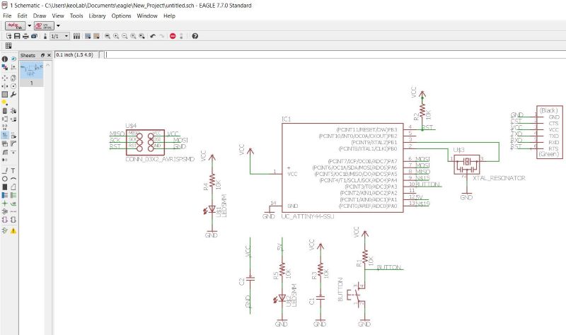
b.My conponents
•ATTINY44A-SSU
•CONN-03X2 AVRISPSMD
•XTAL-RESONNATOR
•LED 1206
•CAP-C1206
•CONN-06-FTDI-SDM-Header
•Button
•Jumper
•LED ORENGE AND BLUE
•RESISTOR
•AND my PCB
c.Complications
For the design of my circuits, I used to use Tinkercad which is a site that allows you to make small circuits on a bred board and also even to do post-design simulations, which were different from my current design, so since I had neither printed nor even designed circuits beforehand, during my design I had some difficulties and complications in finding my different components because I could not search with the right name and also complications to connect the different pins of my ATTINY44A-SSU microcontroller with the other components of my circuit
d.Rectification
After spending a few hours watching Tutorials on YouTube and receiving advice on how to better place the components, to connect them much more easily And also some jumpers that I added. I ended up doing a circuit a little better than the previous one
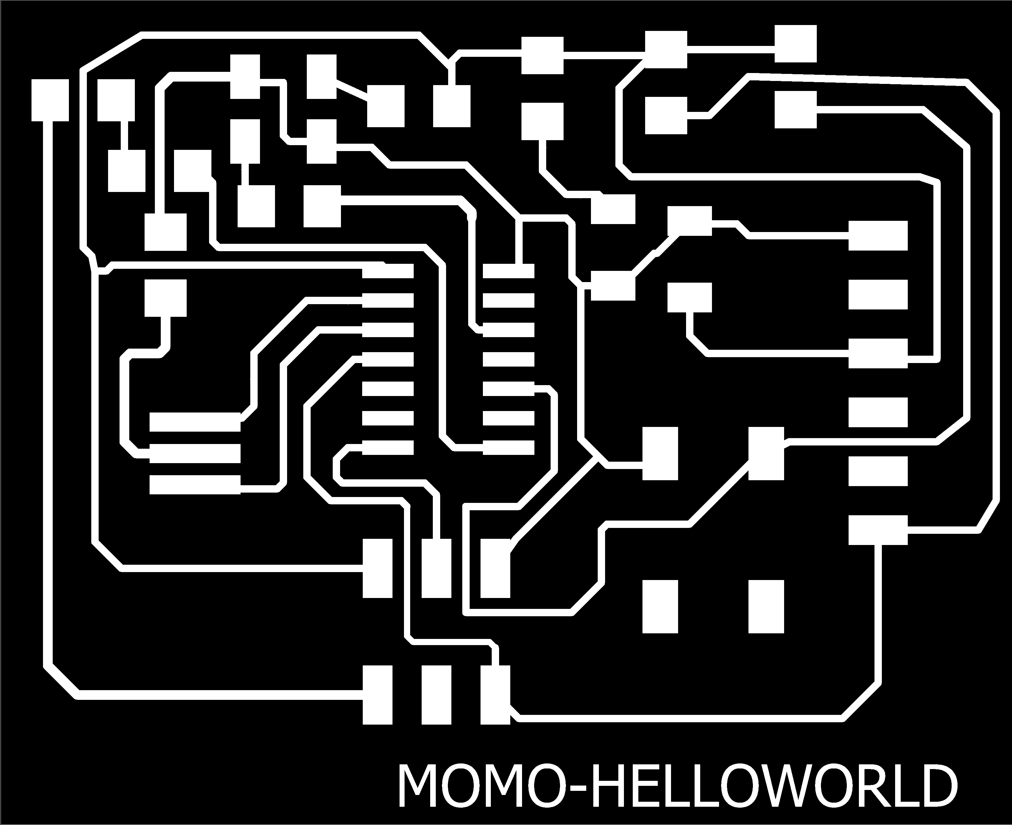
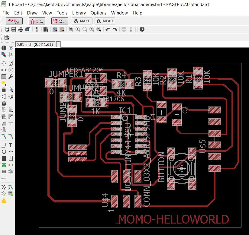
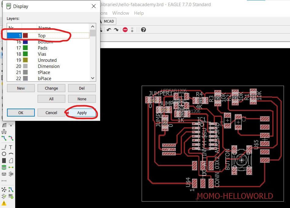
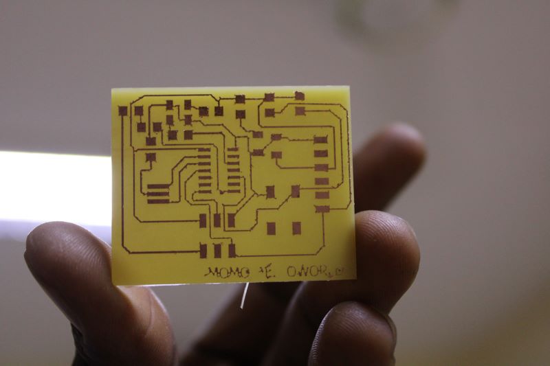
e.Creating the PNG file
Then I export my schematic as an Image in PNG format. But before that I remove the layers that I don't need and I apply. After that I can now save my schematic, first by clicking on Files then Export, then on Image and there I define the folder in which I will save it and I check the Monochrome to obtain a two-color image white and black.
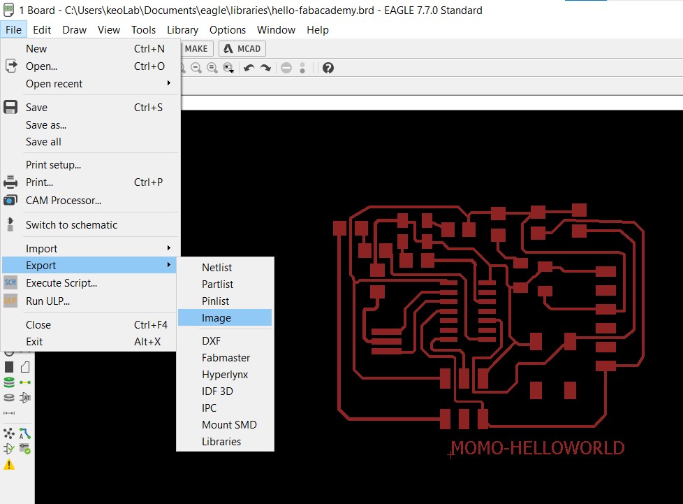
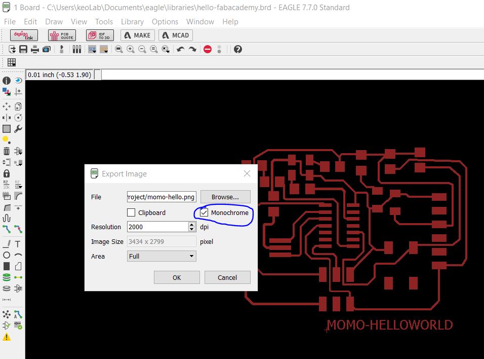
This will allow my schematic to be overlaid on Aspire...
f.My PCB printing
To print my card, I use the ASPIRE 9514 software, where I create a plan with a dimension of 155X155mm for my square block, which I use as a support to accommodate my cards whose size is 76X51.
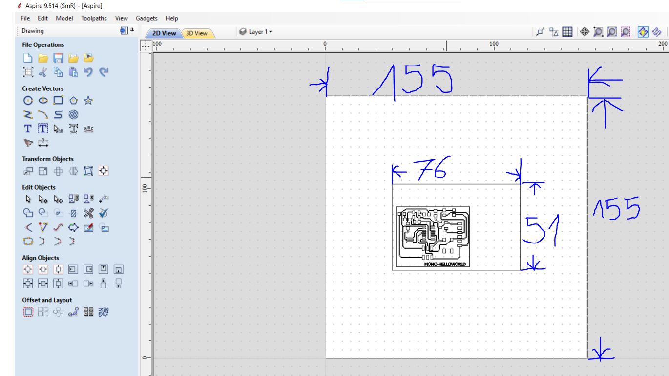
The PNG file that I had saved I import it Then I layer my schematic by going to the toolbar or I choose the Trace Bitmap. Going up with the Number of Colors/Threshold slider to 70 percent and I go to Loose I set to 60 percent after I click on Preview, then Close. After I delete the PNG file keeping only the schematic layer. Then I select the whole circuit and I will click on the Toolpath window where I will choose the working mode. In my case I started with engraving and then cutting. I continue by program my chosen one, always specifying that I work on measurements in Inc. After having programmed my locks. I click on calculate and then switch from 2D to 3D. In 3D I can observe the quality of the work, checking if the lines will not intersect. Then I save the G.code
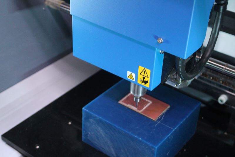
g.MODELA MDX-50
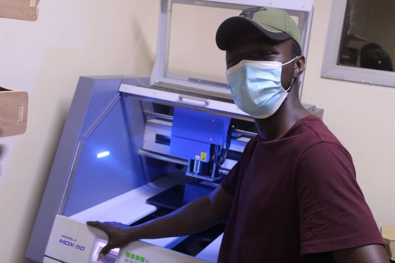
This is my first time using MODELA MDX-50 (this is my first time using it)
Description
It is a machine that uses the subtractive manufacturing process, Subtractive manufacturing is a generic term for various manufacturing processes. controlled machining and material removal that begins with solid blocks, bars, rods of plastic, metal or other materials that are shaped by material removal by cutting, drilling and grinding. its working tool is a milling machine with bits of different shapes and allows to burn integrated circuits.
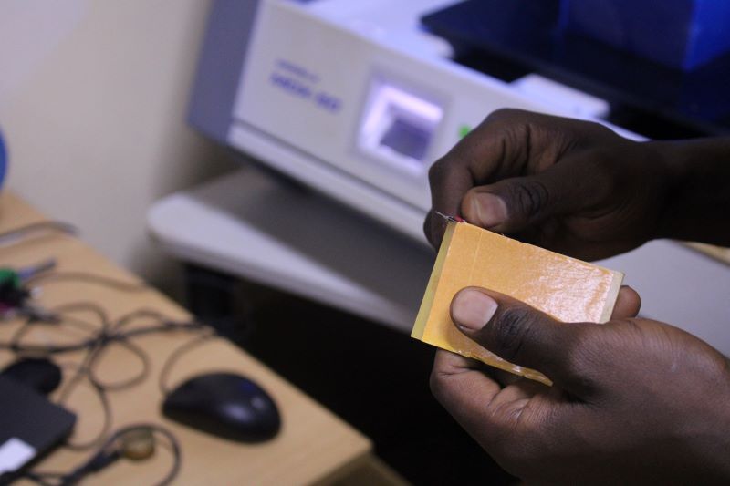
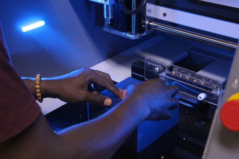
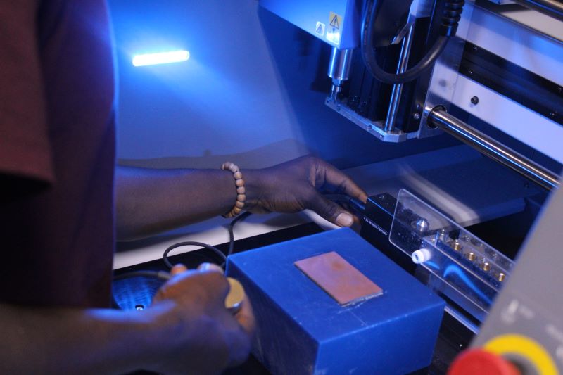
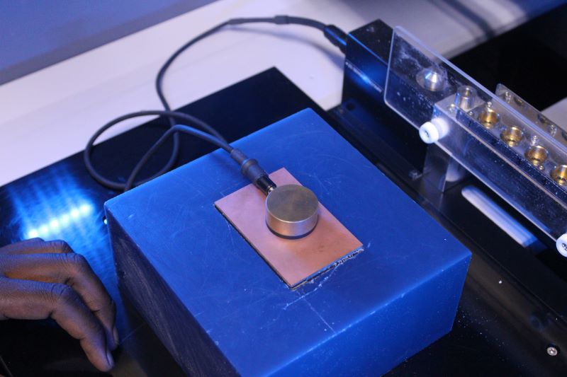
h.Zero axis configuration
I put some glue from my ribbon behind my pcb and I placed it on my little wooden board the same size as my PCBs (it allows me to follow the edges of my board to better place my pcb.) so that he does not move thinking impression.Before any printing, you must first locate the 0 point of the Z Axis with the Vpanels installed on the PC of the machine and then I import the G.code to save. I position my sensor and I connect its cable at the bottom of the mobile plate. I seek the zero point of the Z axis using the the control panel of my machine. I begin by directing it to my sensor. Once you have finished positioning the wick on the sensor, we will lower the wick a little so that it is faster to locate the zero axis because it goes down very slowly so as not to break the end of the wick. we Then I start by installing the Z axis zero sensor that I put on my machining block, put the plate on the mobile plate and then connect it to the bottom of the plate with the sensor cable.

It is a machine that uses the subtractive manufacturing process, Subtractive manufacturing is a generic term for various manufacturing processes. controlled machining and material removal that begins with solid blocks, bars, rods of plastic, metal or other materials that are shaped by material removal by cutting, drilling and grinding. its working tool is a machining milling machine is a milling machine with bits of different shapes and allows to burn integrated circuits.
•I use for my design: For engraving a wick End mill 1/32inch For End Mill 1/64inch cutout. In order to try a quick print test I launched a quick print of a 30inch/s speed but the result obtained was not really beautiful but after tests to carry out it presents a good continuity. But it is advisable to print with a speed of 16inch/min for better printing and not too slow.
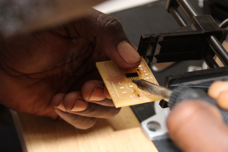
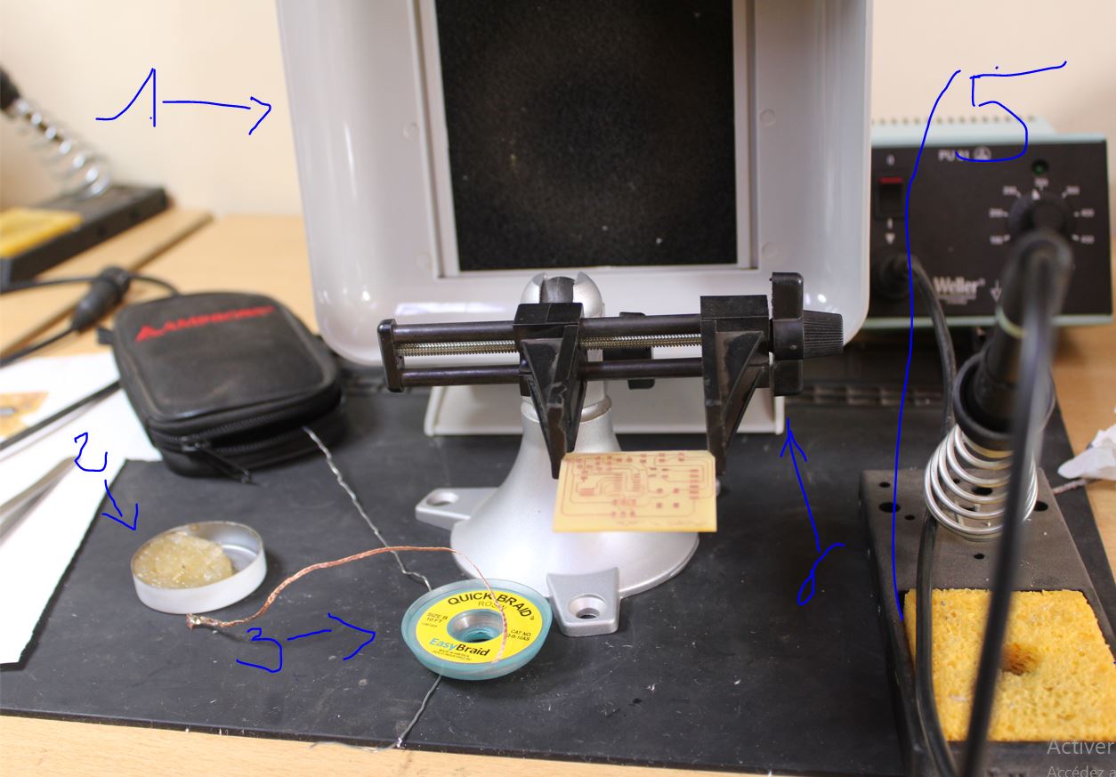
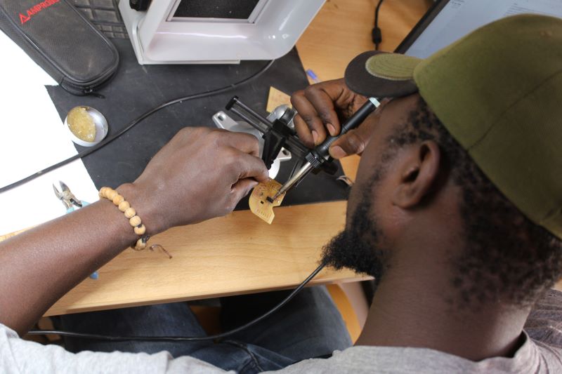
i.Welding
for welding I have the following elements
1 vacuum cleaner
2 solder pomade
3 a copper net box
4 a clamp to hold my PCB
5 we have the soldering iron and the temperature regulators
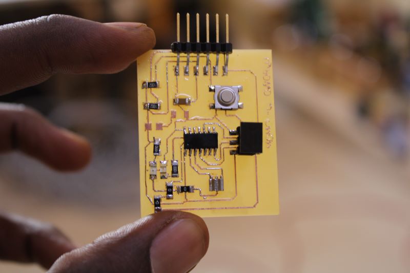
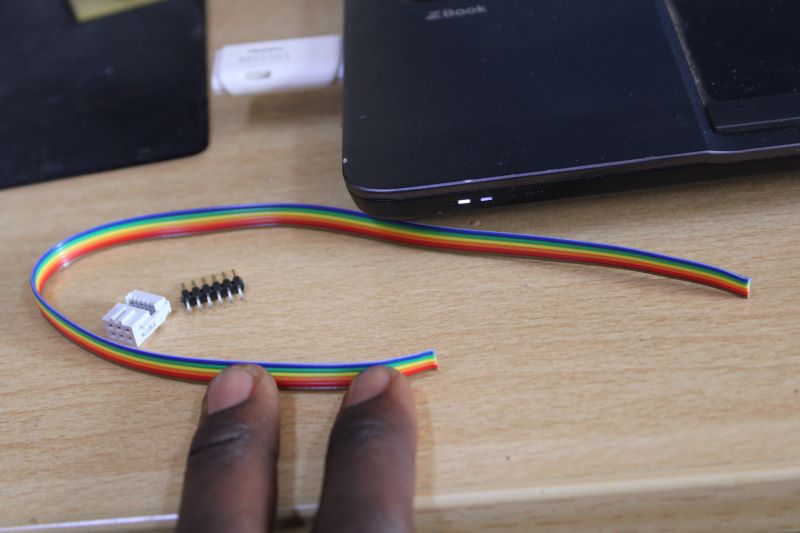
other than that we also have the magnifying glass and the cutter. before starting to solder my hello-world card, I did some soldering tests on an old user card. with the help of my schematic I managed to mount all my components, it was fun. I made an ISP cable using a female pin connector to test my card and 6 pins including my VCC my GND which are connected together and on the other side we have my pins 13-12-11 and 10.
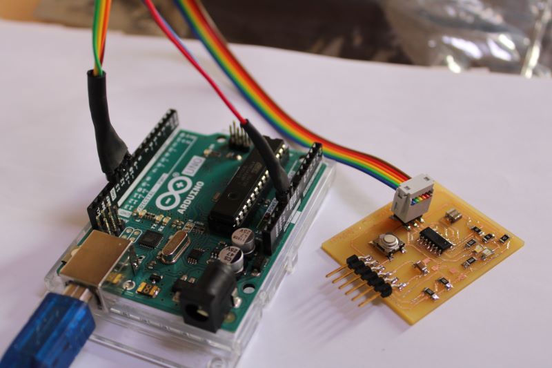
j.conclusion
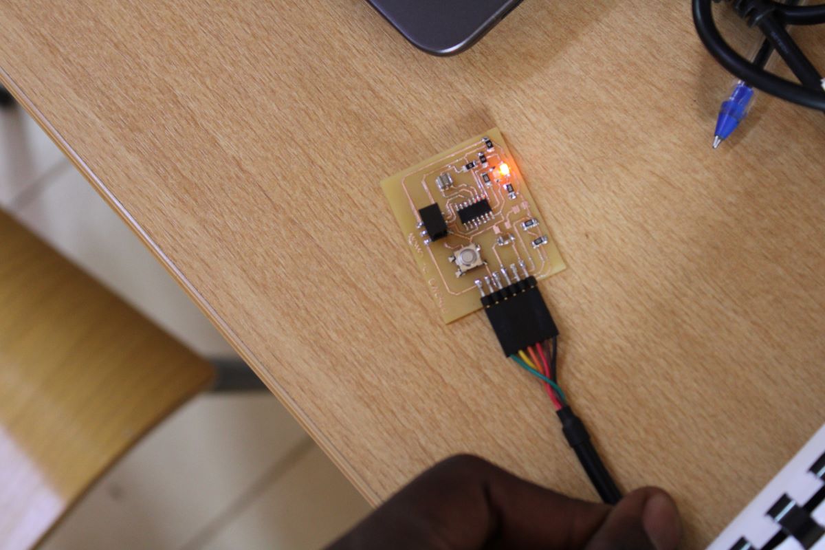
After connecting my hello-world card to my arduino card to download the code. my orange led is on, my orange led is on
