Week11 - Output Devices
Measure the power consumption of an output device. ✔
Document your work (in a group or individually). ✔
Add an output device to a microcontroller board you've designed and program it to do something. ✔
Linked to the group assignment page. ✔
Documented how you determined power consumption of an output device with your group. ✔
Documented what you learned from interfacing output device(s) to microcontroller and controlling the device(s). ✔
Described your design and fabrication process or linked to previous examples. ✔
Explained the programming process/es you used. ✔
Outlined problems and how you fixed them. ✔
Included original design files and code. ✔
Included a ‘hero shot/video’ of your board. ✔
Group Assignment :
In this weeks group assignment we tested out the voltage and power on diffrent output divices. My group chose to measure the power consumption of a DC motor. We hooked the motor up to a power supply and measured the power using an oscilloscope. Then we looked at the relationship between voltage, current, and the motor function/speed. Voltage and current change proportionally, and as they increase, the motor speed increases as well. We also learned about Pulse Width Modulation. PWM is a method of creating a 'medium' using a microcontroller that only has high or low functions. This is achieved by alternating between high and low quickly enough that nothing is visable to the human eye. We tested out different speeds of this with an LED, and noted the correlational relationship between speed and brightness. link to video of the LED power change displayed on the oscilloscope
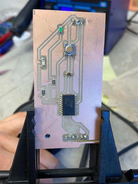
Reusing ATtiny1616 Board :
I used my attiny 16160 board I milled and designed for the electronics design week for this weeks project. After The many issues with milling I wanted to avoid doing this week to give myself a break! Information on how I milled and designed this board can be found Here
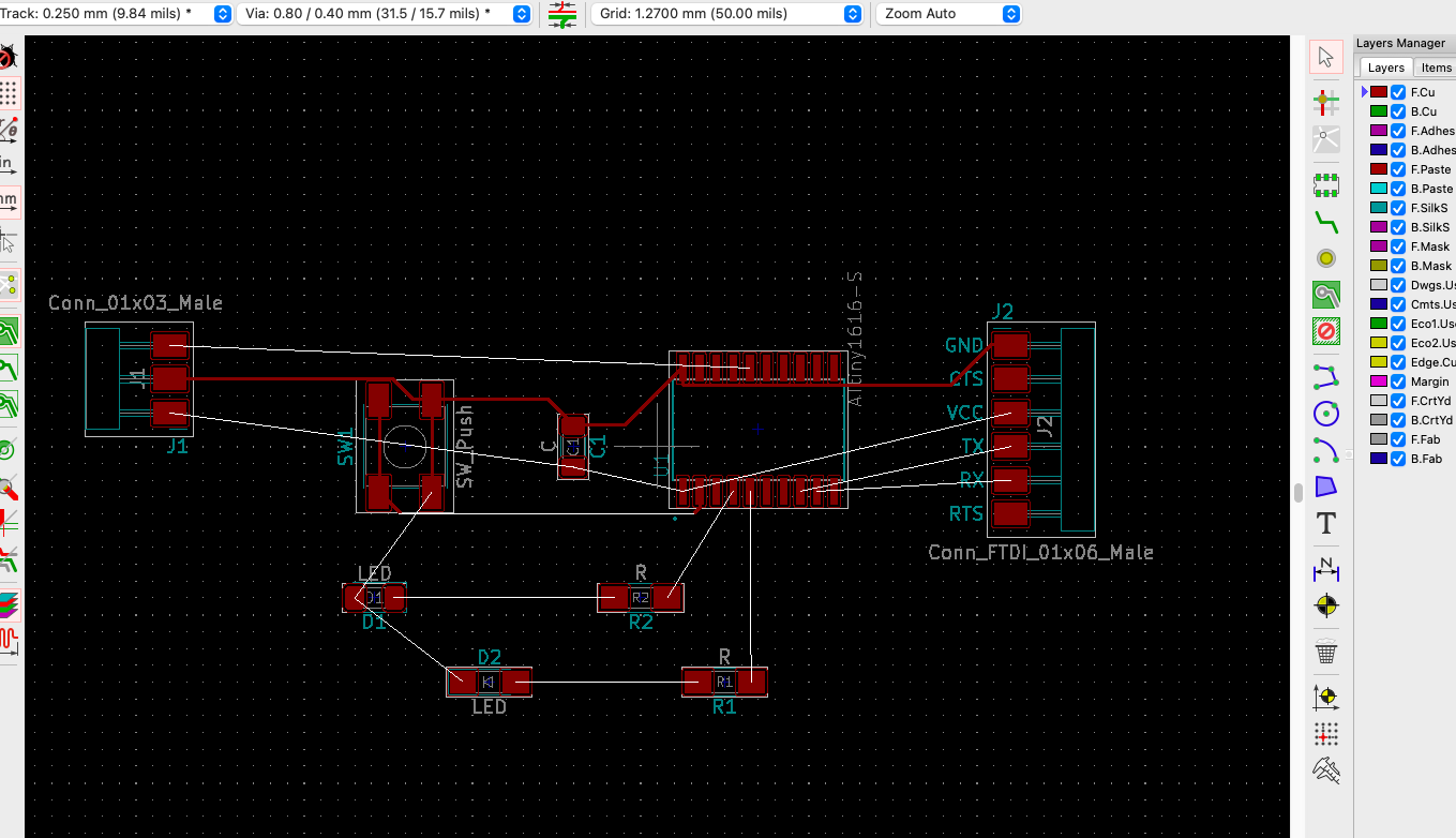
Here is my attiny kicad design
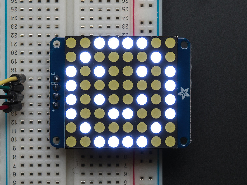
I decided to use a MAX7219 LED Dot Matrix Module as my output device. Here is the link to the model link to model
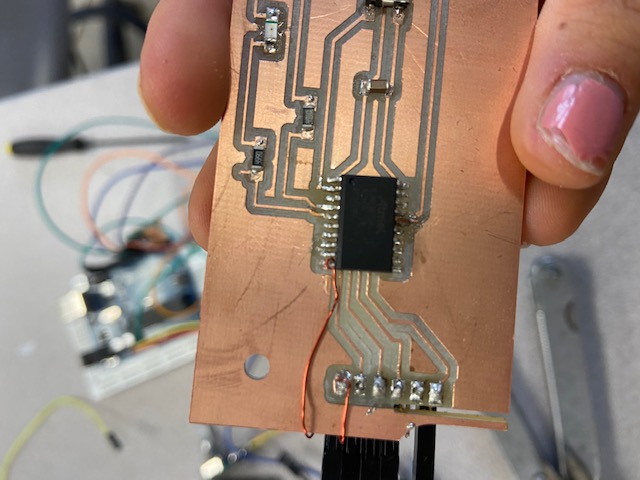
I had to first add a fly wire on my atTiny1616 board because there were not enough pin connections for the MAX7219 LED Dot Matrix Module. I did this by soldering on the copper wire to connetct the an unused attiny pin to my RTS pin.
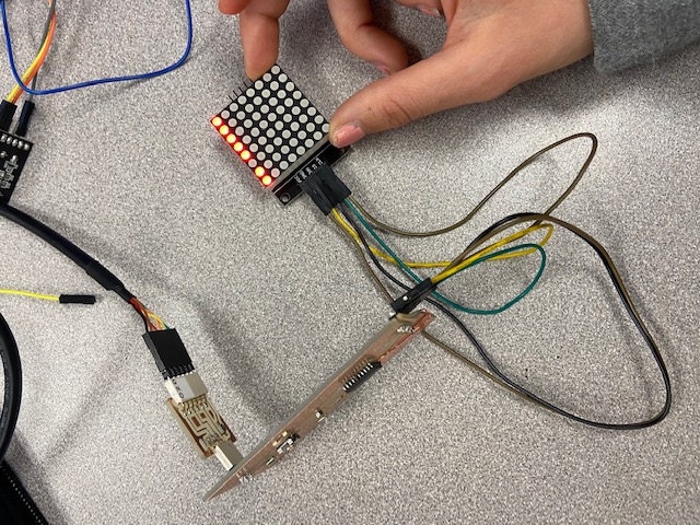
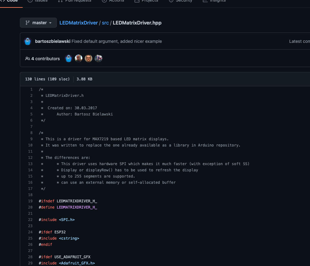
Then we check the multimeter to make sure all my connections where correct. Once everything was hooked up, I did a little research on the MAX7219 LED Dot Matrix Module to see how it would funcion with my board. I found code from Bartosz Bielawsk who used the LED Dot Matrix to code the divice to type out letters based on the lights being lit on the board. Here is a link to the git site here
coding
I downloaded the code files and uploaded them into arduino.
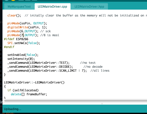
We disabled the hardware spy as it was on the wrong pins. Then reroute the libraries spy parts instead used the shift down function which is a software spy which was slower and less performant but was the best way of making the lights turn on properly We switched the software using shift out and made some tweaks to move the pits around Then I switched the top and bottoms lines of code so the LED lights would not be reversed Then Switched the pin numbers from 8 and 9 to 6 and 7 because those were the pins we were using for the board setup I had with my 1616 board
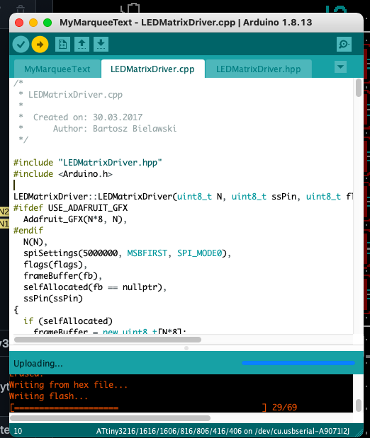
Then I pressed upload and...After a few more tweeks it worked! Here is a link to a video of led lights reading my coded message link
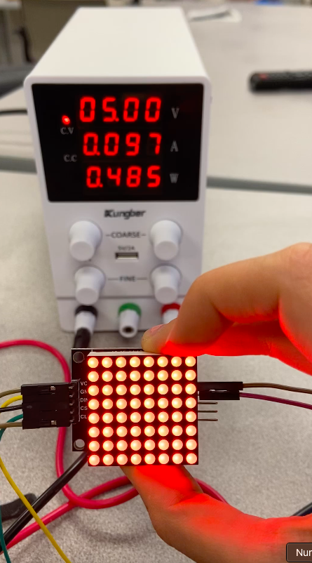
Here is my board connected to the DC Power Supply, You can see the voltage drop when led lights are not displayed on the screen in comparsion to when all lights are turned on, the full 5 volts from the DC power supply get used.
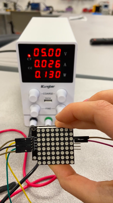
video of LEDs next to DC Power supply link
video my full coded message I programmed onto the MAX7219 LED Dot Matrix Module link