Week9 - Input Devices
Group Assignment:
Measure the analog levels and digital signals in an input device
Individual Assignment:
Measure something: add a sensor to a microcontroller board that you have designed and read it
Programmed your board. ✔
This week assignment content:
Group Assignment:
The Group Assignment For the group assignment we recorded the specs for each of the listed boards.
Data Sheet for BorFeather M0

Board: BorFeather M0 lora 900MHz
Processor Family: ATSAMD21G18 ARM Cortex M0 processor,
Bus Width (bits): 20 bytes
Clock Speed: 256K of FLASH
Memory: clocked at 48 MHz and at 3.3V logic
Number of I/O pins: 8 x PWM pins
Logic level voltage: 3.7V Lithium polymer batteries and built in battery charging. You don't need a battery, it will run just fine straight from the micro USB connector. But, if you do have a battery, you can take it on the go, then plug in the USB to recharge.
Pinout diagram: link
Datasheet: link
Data Sheet for RedBoard

Board:RedBoard
Processor Family:#ATmega328P
Bus Width (bits): 8 bit
Clock Speed: 16MHz Clock Speed
Memory: 32k Flash Memory
Number of I/O pins: 14 Digital
Logic level voltage; 5 volts
Pinout diagram link: link
Datasheet: link
Manufacturer:link
ADA Fruit Mini Microcontroller

Board:ADA Fruit Mini Microcontroller
Processor Family:#ATtiny85 (AVR)
Bus Width (bits): 5.25K bytes
Clock Speed: 16 MHz
Memory: 8K
Number of I/O pins: 3
Logic level voltage; 5 volts
Pinout diagram: link
Datasheet:link
Manufacturer: link
ATTiny1616

Board:ATTiny1616
Program Memory Type: Flash
Program Memory Size (KB): 16
CPU Speed (MIPS/DMIPS):20
SRAM (B): 2,048
Data EEPROM/HEF (bytes): 256
Digital Communication Peripherals: 1-UART, 1-SPI, 1-I2C
Capture/Compare/PWM Peripherals: 2 Input Capture, 6PWM
Timers: 1 x 8-bit, 3 x 16-bit
ADC Input: 16 ch, 10-bit
Number of Comparators: 3
Temperature Range (°C): -40 to 125
Operating Voltage Range (V): 1.8 to 5.5
Pin Count: 20
Low Power: Yes
Individual assignment
Designing, milling, soldering, programing a board that uses a rotary encoder to turn on neo pixels
This week I created my board I was going to use for my final project lantern. So see the full finished lantern visit my final project page
Roland SRM20 Specifications
SO our school is completely gutting and renovating the building where our lab is located. In late march our lab had to completely move out and relocate to a building across campus. But then...about a week after the lab finished moving in, the fire department shut our lab down because of safety concerns. So all our lab equipment had to be dispersed across campus to various buildings since not just one building could contain our lab. I did not think this would be a big issued until the location of the soldering station (digital lab) did not have enough female to male wire connector, or someone took the usb port back to the main lab (bookstore lab) when I was working in the digital lab… or I was in the bookstore coding and then fried my attiny and had to walk back to the digital lab to solder one pin...or when there was no working multimeters in the bookstore or when I the power supply was in the digital lab or was it in the fiber lab?? Here is a photo of my step count during the day. I believe I went back and forth over 15 times gathering everything I needed just to work on my board. I now all went to the soldering stationThis was a bit of a frustration. Our fab lab was divided across campus because our initial new location was shut down because of the fire department and safety issues of having all our lab tools located in the converted book store now digital lab.

Here is a photo of my step count during the week I started to resolder and code my board...
My design was to create a board that used a rotary encoder that programmed neo-pixels to turn on and off one by one when twisted the rotary encoder knob.

At first I used a breadboard and arduino uno to figure out what components I would need to use and how to connect them in order to program the neo pixels and rotary encoder. Here is my bread board set up, I used a pre-uploaded neo pixel test code that already existed on arduino to check the connection of my neo pixels and to make sure they all worked!
video of my working lights on the breadboard hooked up with a rodary encoder !

First I designed my schematic in kicad. My first 3 boards used an attiny 3216 microcontroller, but then when each board kept failing to upload during the programming phase of the project, I had to completely redesign the board and use a ATtinly402 since we ran out of 3216 controllers.
 First I designed my schematic in kicad. My first 3 boards used an attiny 3216 microcontroller, but then when each board kept failing doing the programming phase of the project, I had to completely redesign the board and use a ATtinly402 since we ran out of 3216 controllers.

Here are the file links to my attiny204 schematic and other documentation. link here!
 Here is the process of exporting my file designs from illustrator, into mods, then exporting each trace, throughhole and edge cut file to an rml file, so then I could upload each cut into the Roland.
Here is a video of me checking my taces path on mods before I export the cut to the roland click here
Roland like usual, gave me a lot of issues making sure the cut was not too deep but also not too thin… this took about 10 tries, and a lot of frustration to finally get it correct. I figured out I needed to press slightly down on the copper board while setting the bit so it would cut just deep enough. (well cut board.. Or a few)
 Here is a video of old roland click here
Next I moved to soldering each of the components onto the board. I learned that I really needed to be careful not to get extra solder under my attiny because when we checked with the multimeter it kept reading I had short circuits!
 Finally after I had a soldered board with no short circuits… I moved on to programming the board.
link to my code
Finally after I had a soldered board with no short circuits… I moved on to programming the board.
link to my code
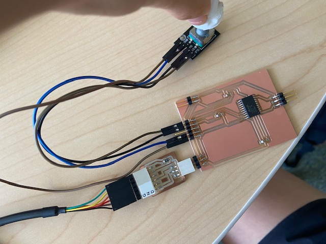
 After a frustrating hour I realised it wasn't my board or code that was an issue...the usb port connector I was using was broken. After switching ports, my code correctly connected to my board.
Here is the link to many videos of my process of trying to get the neo pixels to work!! link here!
I also accidentally fried my attiny and had to walk the 5 minutes back down to our soldering station to fix it, and pray that was the only issue when I marched back up the other part of our lab. Lucky after I added on my new attiny 402, programmed it, and plugged in the wires connections to the neo pixels and rotary encoder...IT WORKED!Thank goodness that was all that had gone wrong.
Here is a video of everthing working!! link here!
Here is the link to my project files link here!