Electronic Design Week
Professor Goodman awarded me with “most time consuming mistakes made” out of everyone in our class for this week's assignment. Believe it or not I encountered so many mistakes, I am not sure if I have remembered to included every single one in this documentation.
This week assignment content:
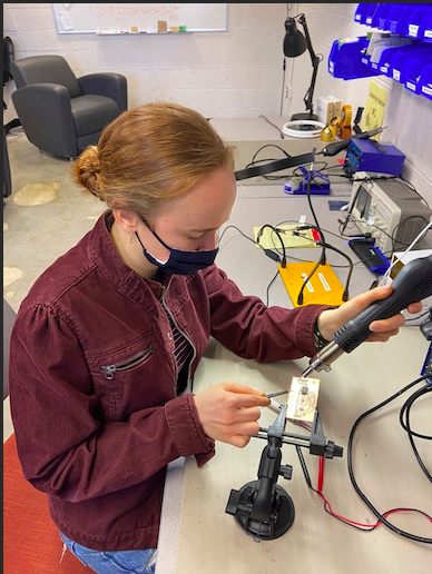
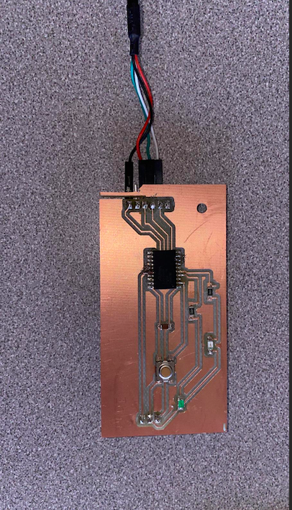
Design board using KiCad, Export into Mods, Mill Board using Roland, Solder components and program the board.
KiCad
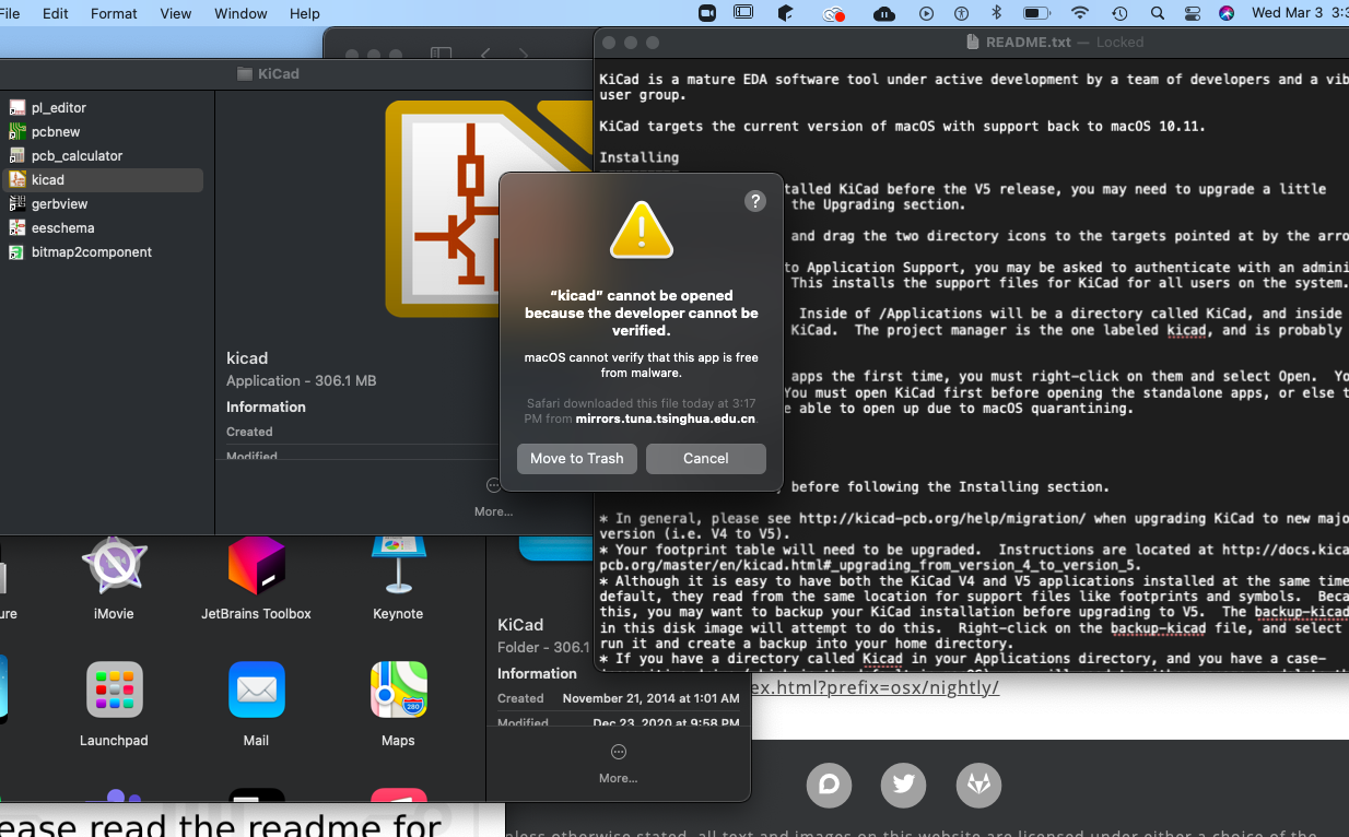
To start, Downloading Kicad was a longer process than most people dealt with in my class. We realized the protection features on my mac made it more difficult for the software to be expected onto the computer. I also was not able to download the component library in kicad but finally after deleting and then re-downloading the program about 8 different times before it finally worked.
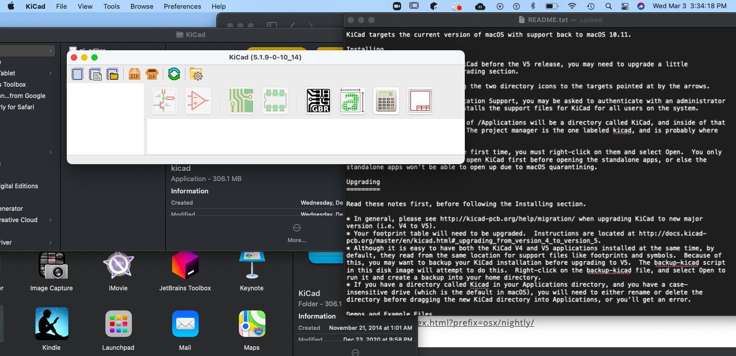
Kicad Finally Downloaded
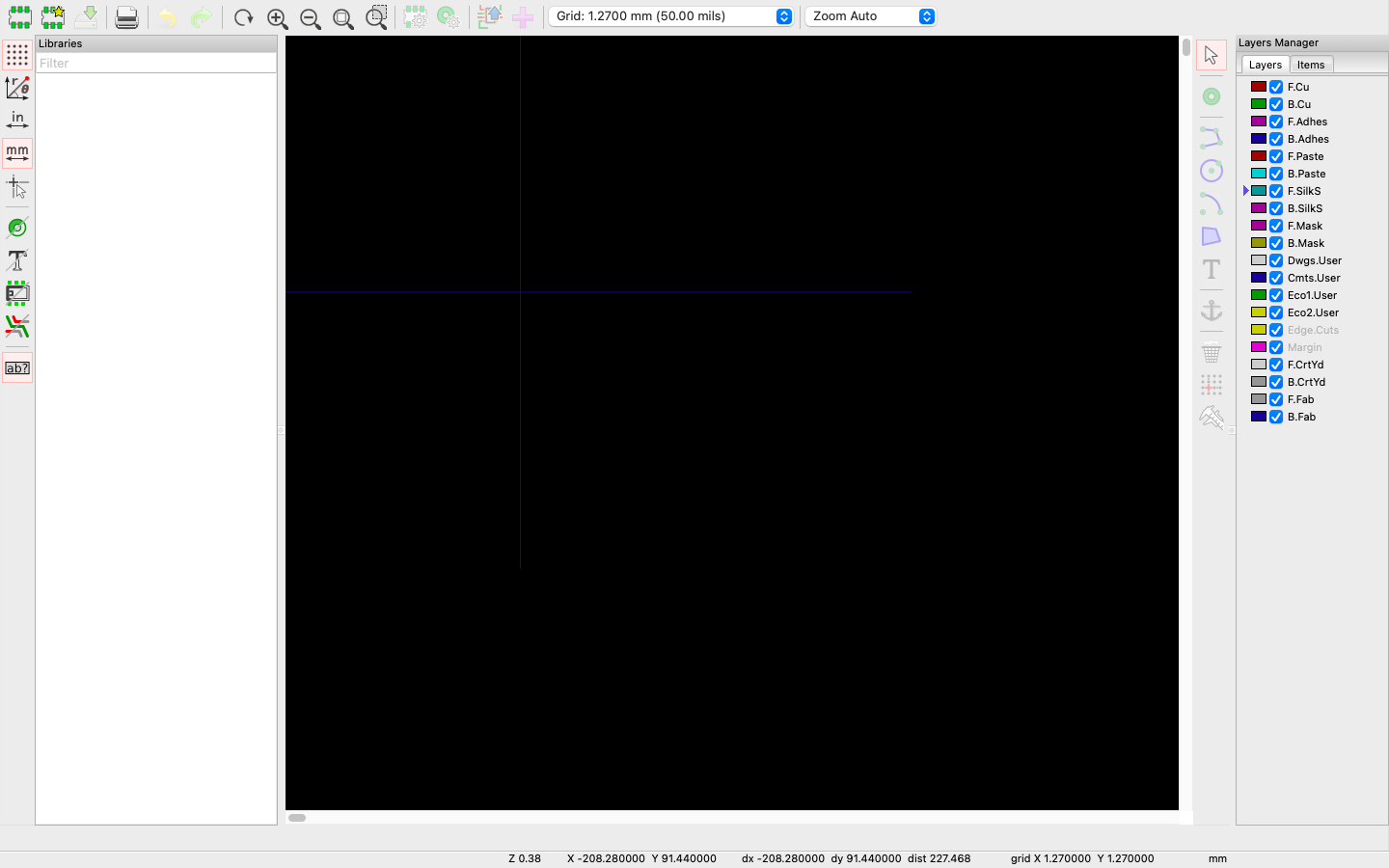
Library photos not showing up...
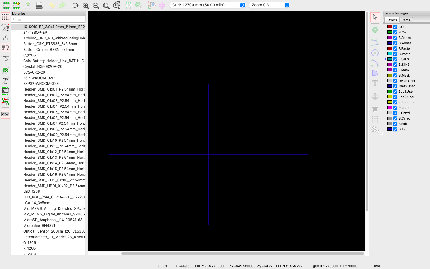
Now working! and I also downloaded the Fab file libary shown in the photo.
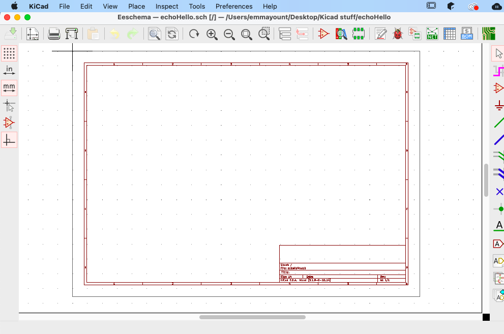
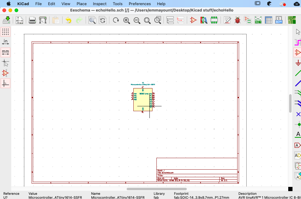
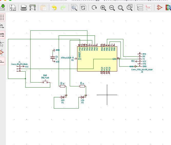
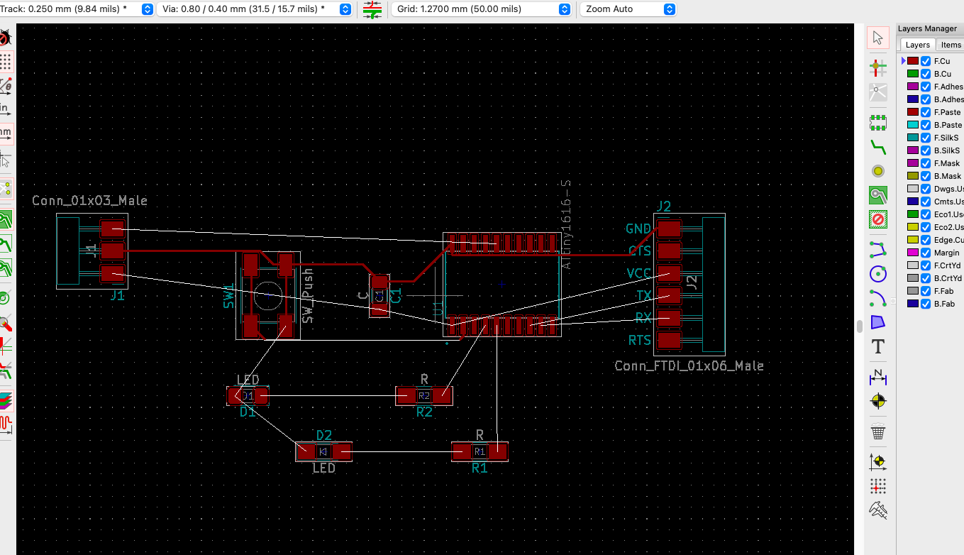
Here I am in the design space where I started assembling my components for the echohello board.
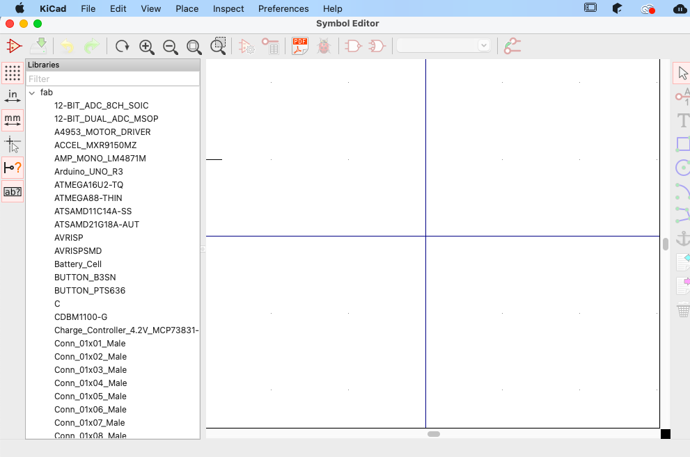
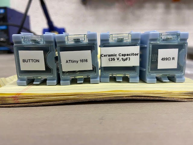
My fab components shown in the filter libaray
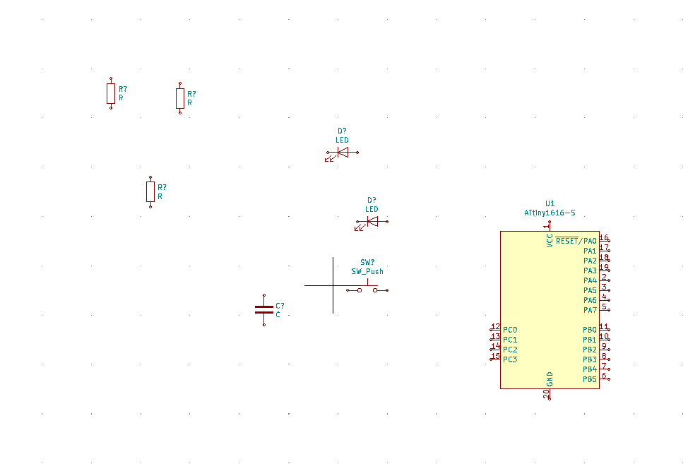
In our lab we only had access to the ATtiny1616 microcontrollers, so here I am adding that component to my design
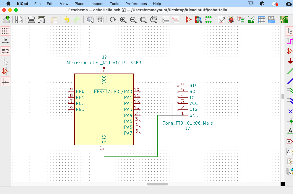
Next I added the Conn_FTDI_01x06_Male
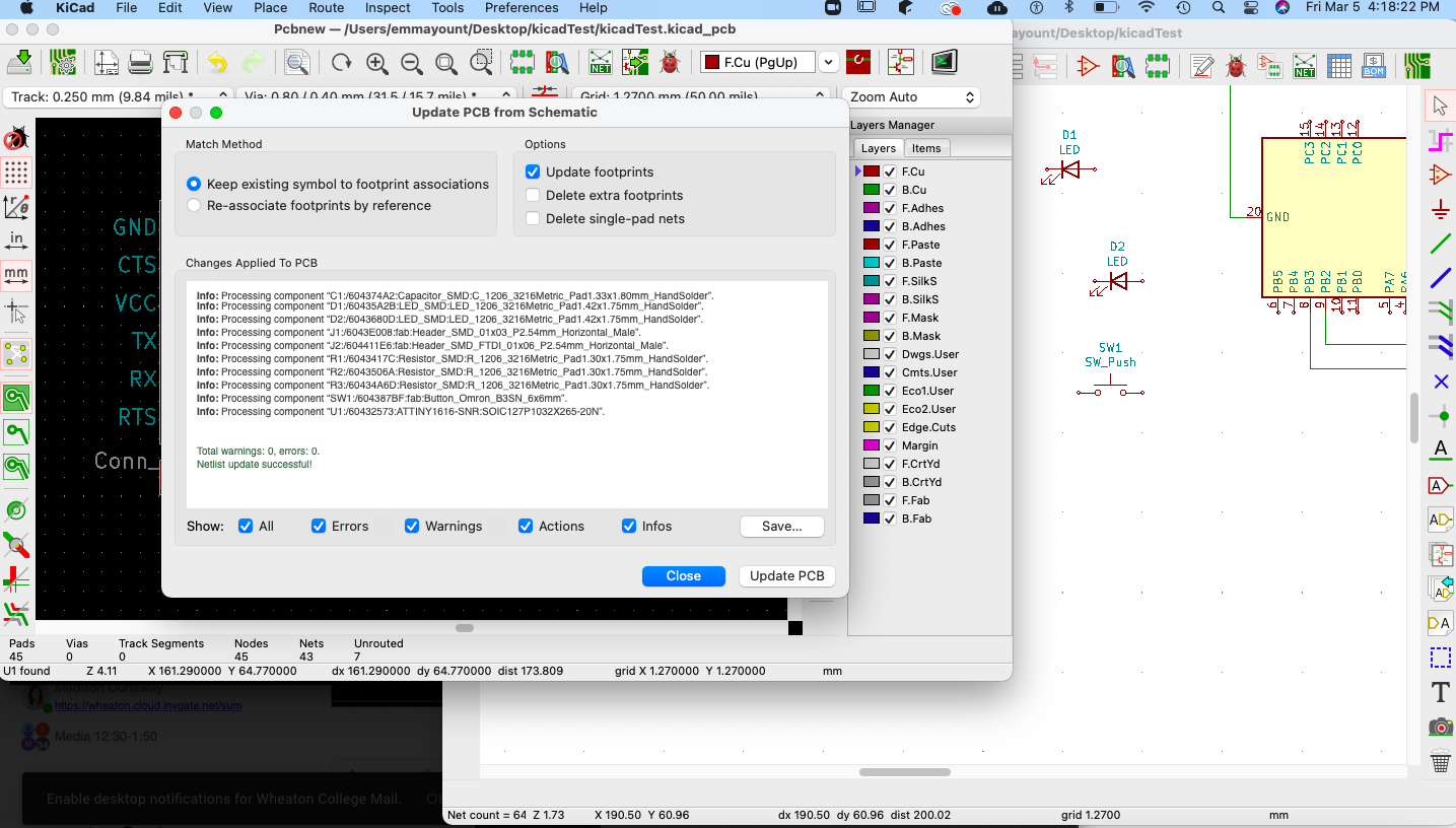
Here are all my components added to my board. Next I moved each peice around,
And then wired them to their correct connection based on the models desplayed in the fa Acadomy documentation site
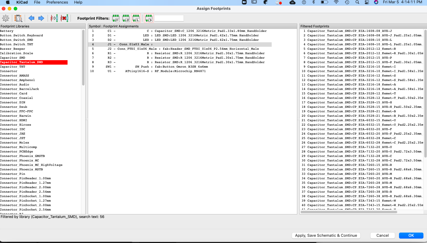
Next I assigned footprints to each of the componets in my design using the footprint filter tool
All the footprints are nested and working!
Here is what my board looked like (the first time I created my design...)
>Then I watched a few tutorials on how to wire my creat my board tracings
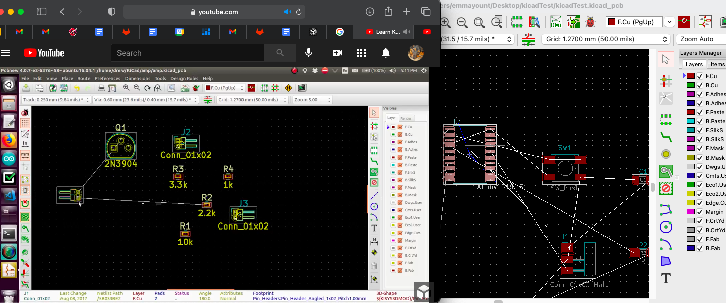
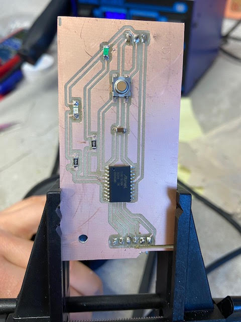
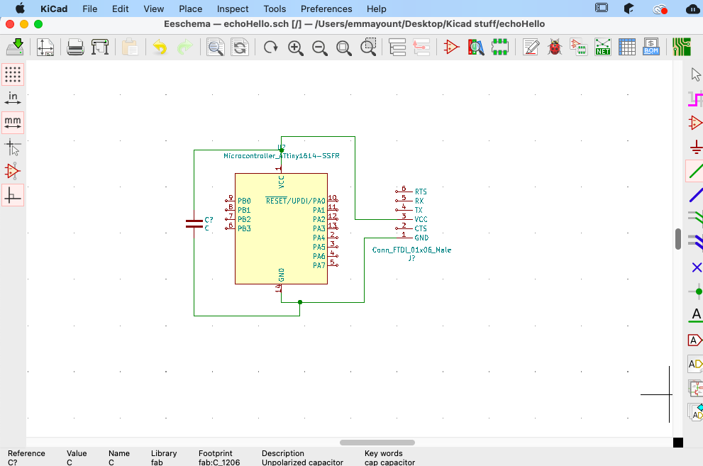
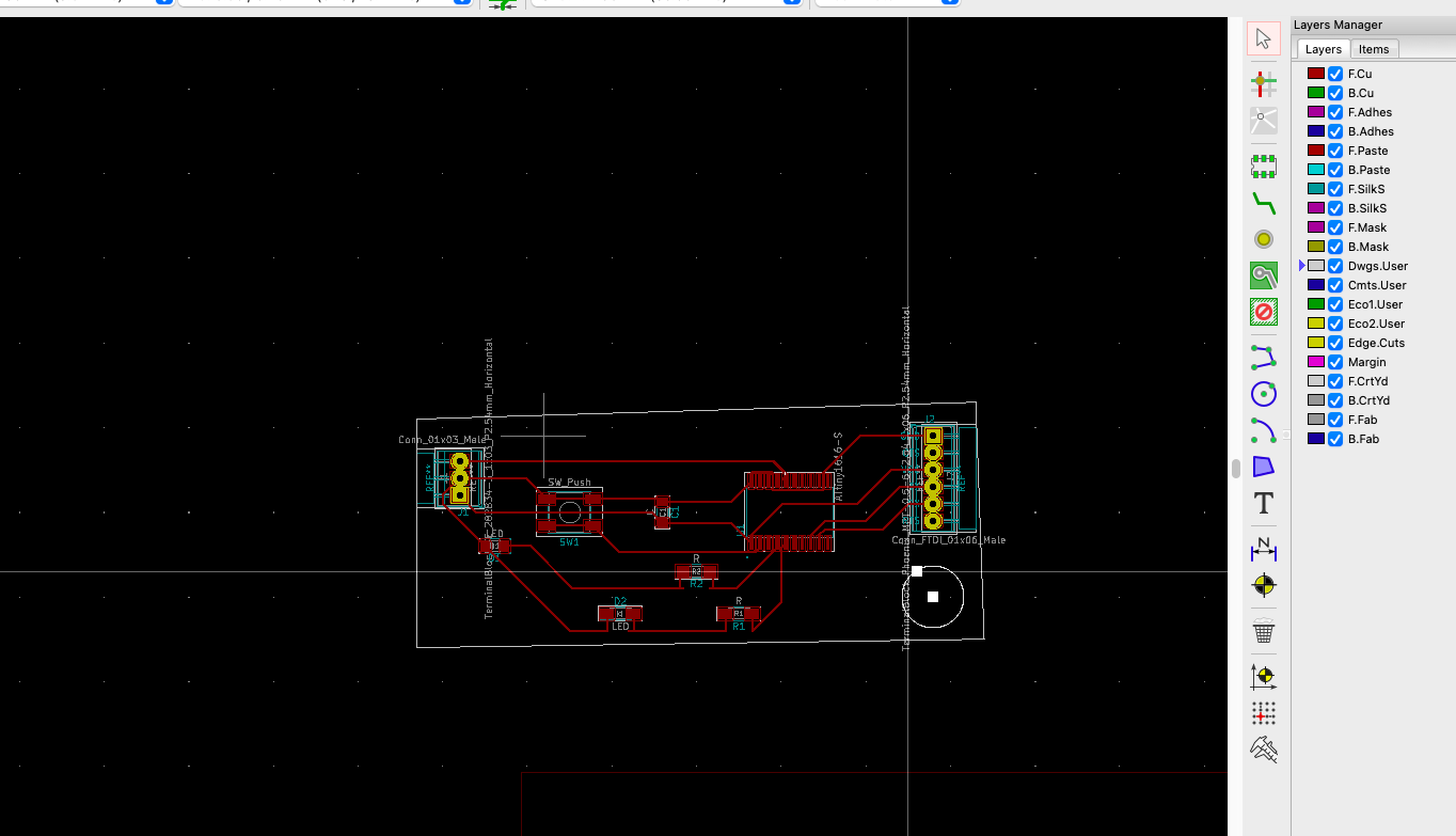
Initial placement of all the components was so messy I should start over before the next step of designing the traces. So then I started over from scratch and resigned my whole board. Here is what it looked like the second time.
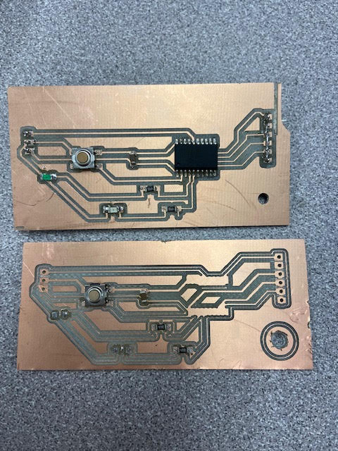
Here Is my board after adding the outline and holes
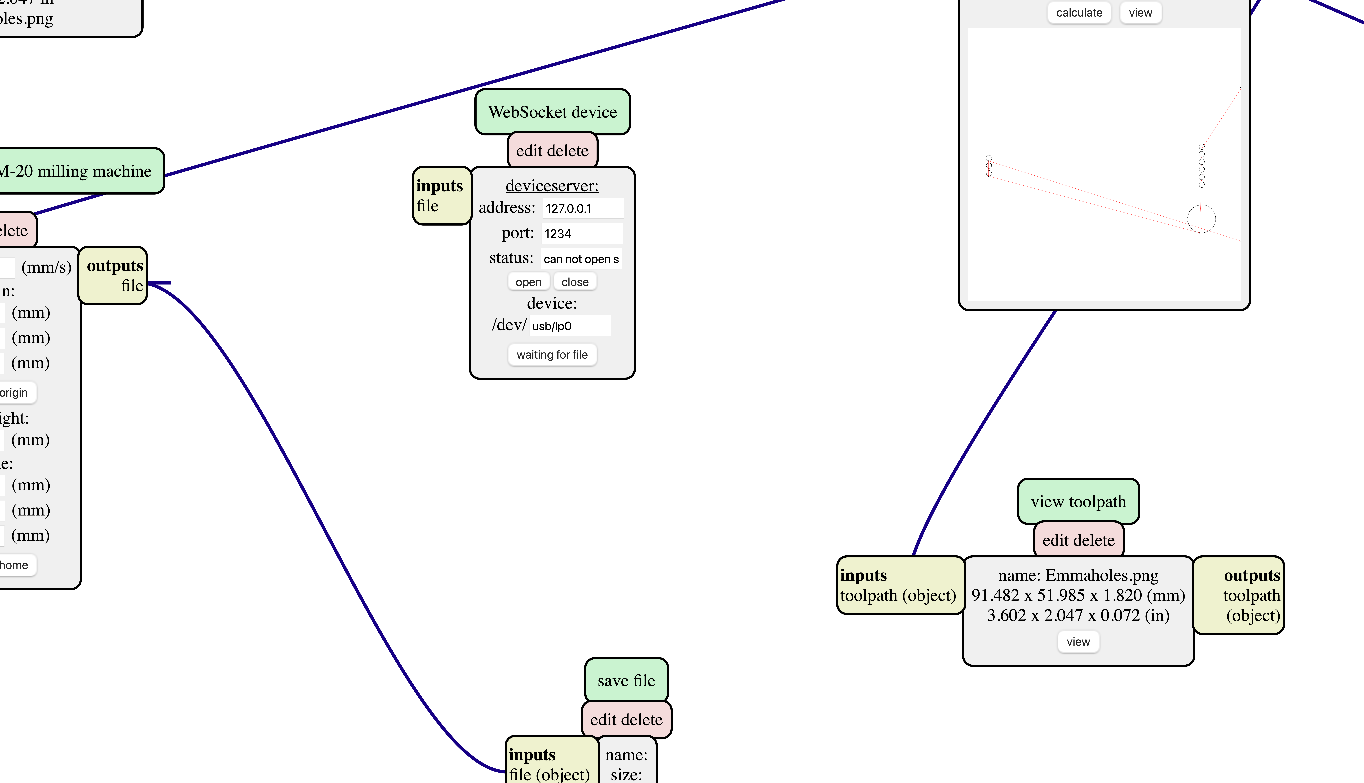
MODS:
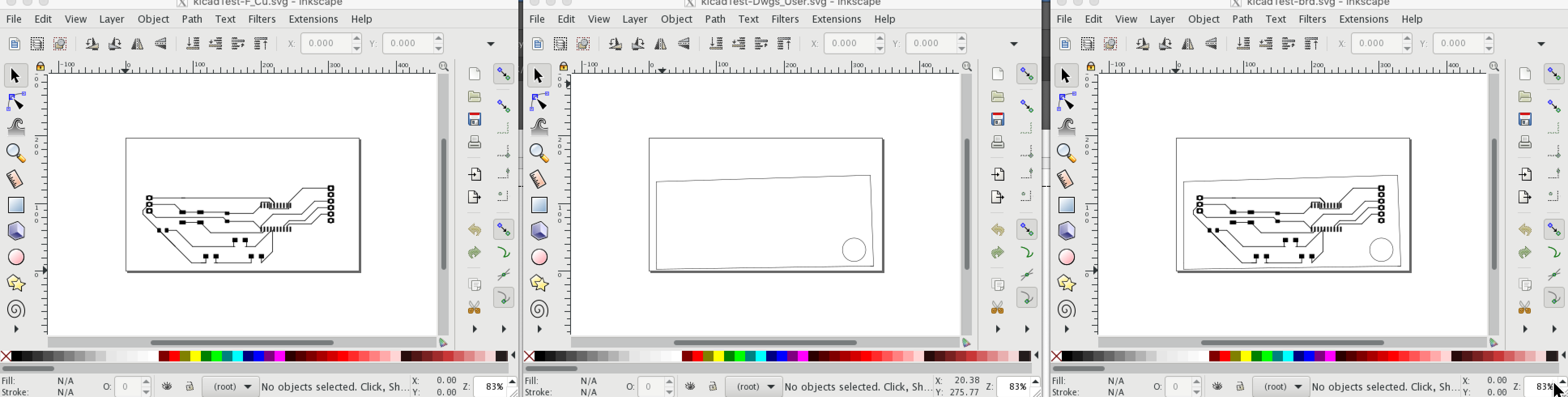
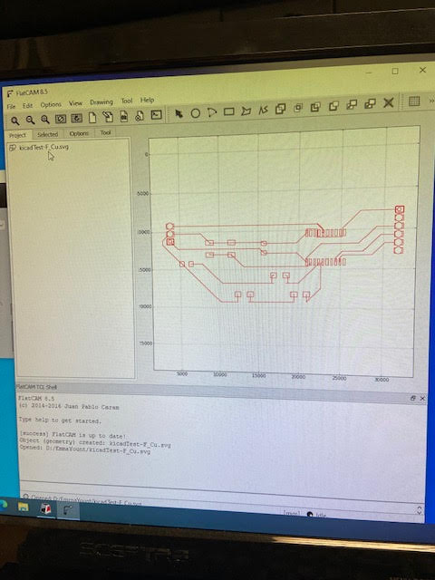
Next I exported my svg files to inkscape and set up the layers to be then exported into mods.
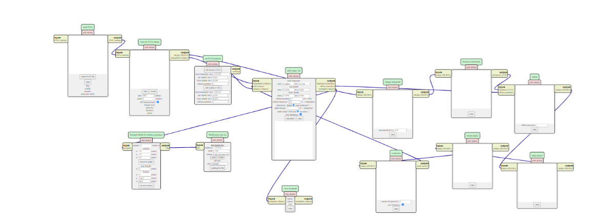
In Mods we inverted each file so that the traces would cut in the proper direction and distance.