Computer-Controlled Cutting
For this week's assignment we had a group and individual project. For the first assignment we worked in groups to create test cuts on the laser cutter using varying settings. Then for my individual assignment I designed a laser cut, and then assembled a parametric 2D press-fit construction kit. My group also designed and constructed vinyl stickers using the vinyl cutter and the sure-cuts-a-lot software program.
This week assignment content:
4.1. Characterize your lasercutter's focus, power, speed, rate, kerf, and joint clearance.
4.2.Design and laser cut a parametric press-fit construction kit.
4.3. Vinyl cut of a vector design.
4.1.
We started by designing a simple shape in fusion that we then exported to illustrator on the computer connected to our laser cutter.
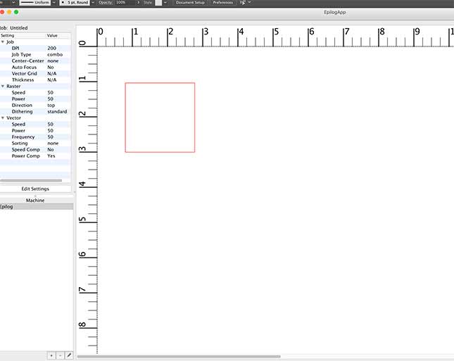
Here is our test square in preview mode in the epilog laser application
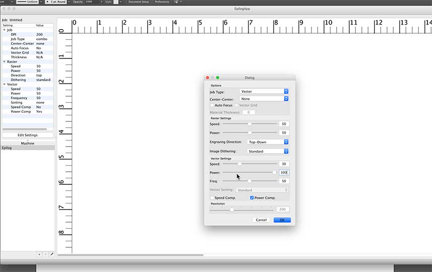
for each square we adjusted the Speed and power but kept frequency at 50%. Then we changed the frequency for the last two squares to see if that would affect the cut as well.
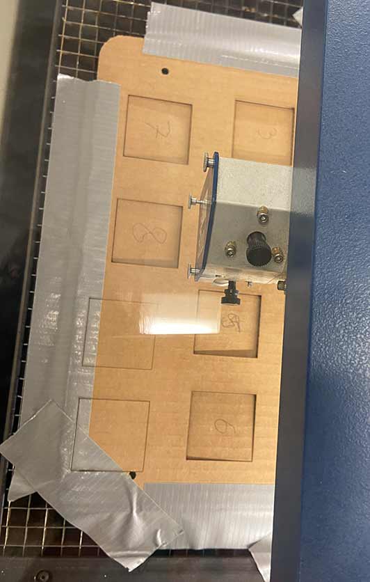
Here are our numbered test squares getting laser cut in action
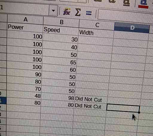
We measured the dimentions of our square after each laser cut variation and documented it in our spreadsheet.
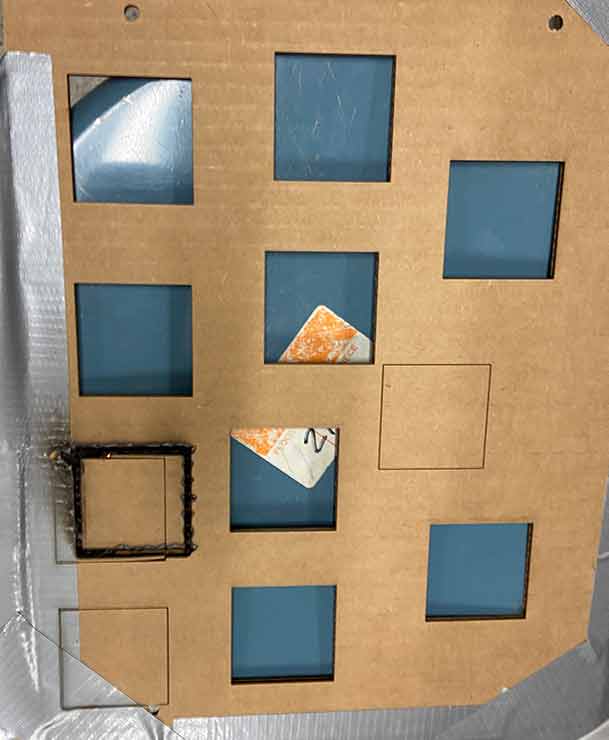
All our squares cut and removed
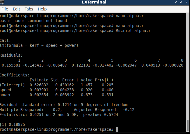
Then we ran our data we documented in the spreadsheet through an r program to make a linear model to show the change in kerf. We found that the change in power and speed did not change the laser cut kerf distance in our cardboard. After we changed the focus for our last test square we found this did affect the kerf.
4.2.Design and laser cut a parametric press-fit construction kit.
For this task, I used Fusion 360 to design my parametric press-fit construction kit. First, I did some search about the parametric design concept. Here is a video I found helpful link here! Parametric design is when you are defining some variables with specific values that can be used anywhere in your design by referring to the variable name. Parametric variables values can be changed during any design phase, which gives the user more design flexibility and easier control.
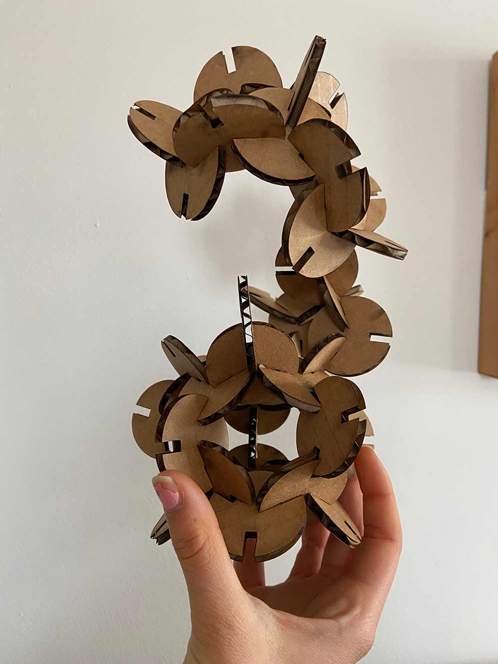
For my design I chose to create a simple circle that I then added interlocking slits that could be connected in multiple ways to create an abstract sculptural shape.
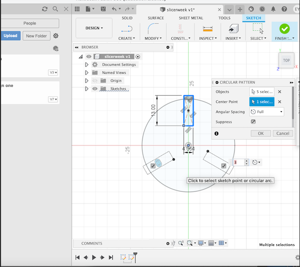
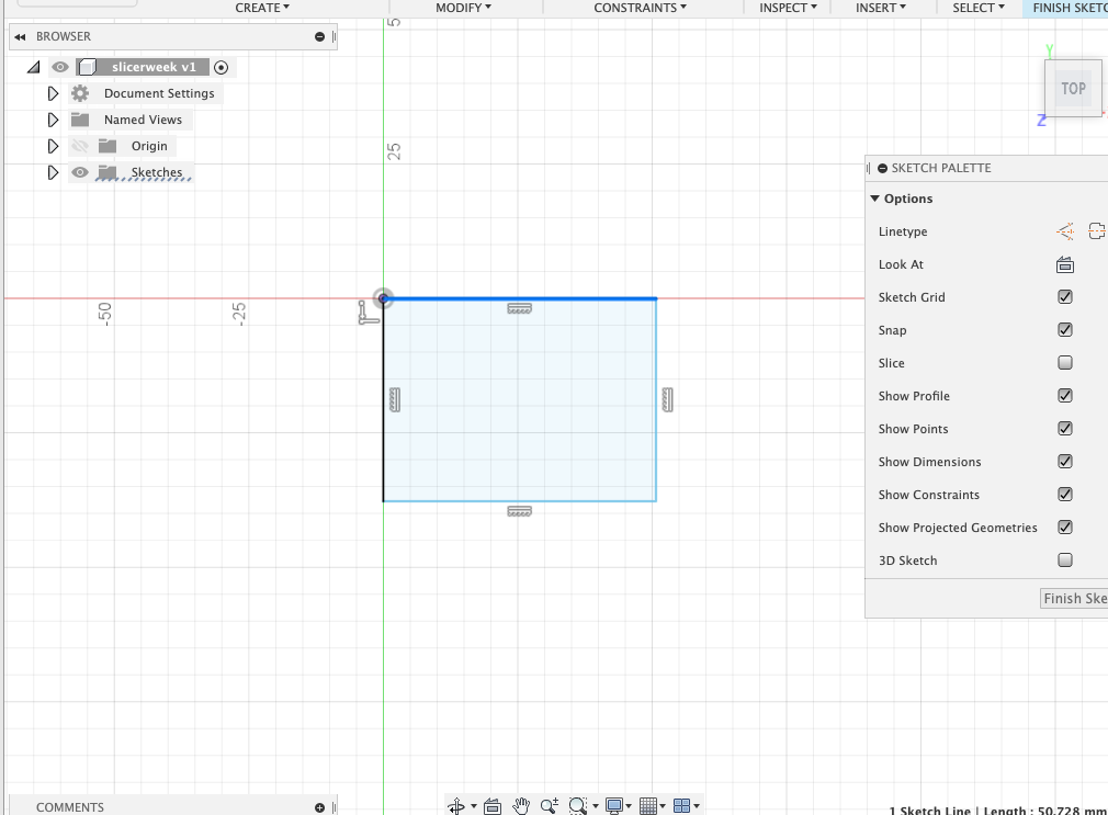
Here I am adding my contraints to each of the three slits so that they are all equal in length, depth and distance from eachother.
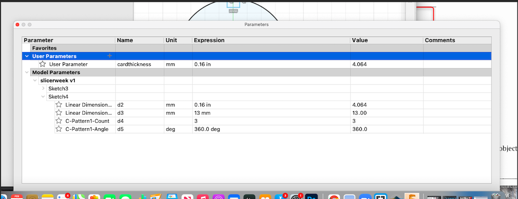
Next I added my parametric dimentions for the cardboard thickness and depth of my interlocking slits.
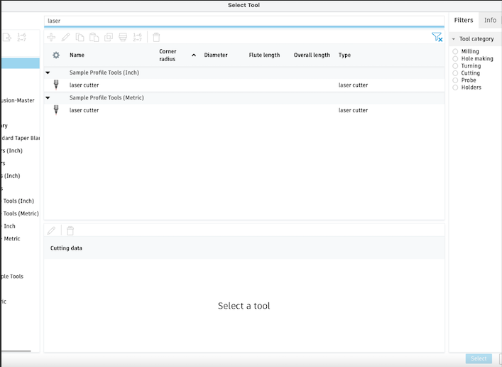
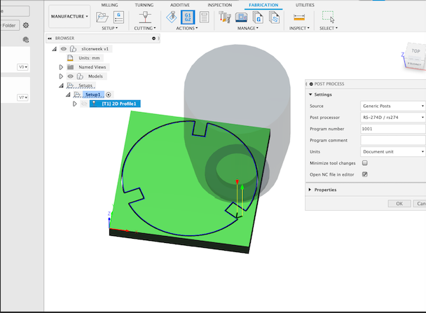
Here I am selecting the correct laser cutter and making sure all the tool paths are on the right settings so it will be ready to export into illustrator.
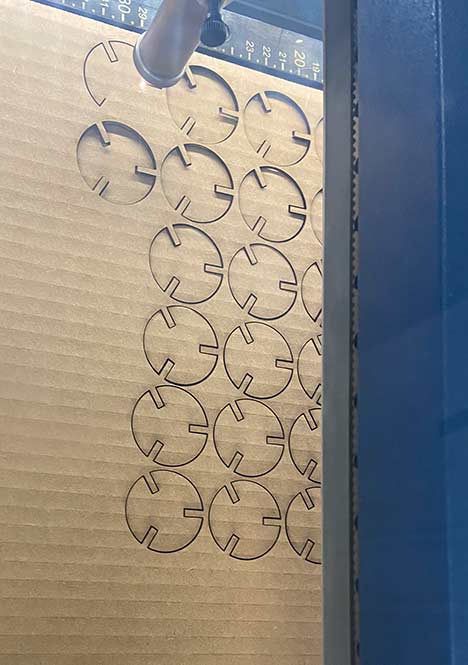
Cutting my design a LOT of times!
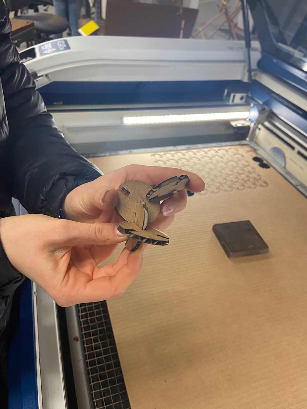
starting to Assemble it together...
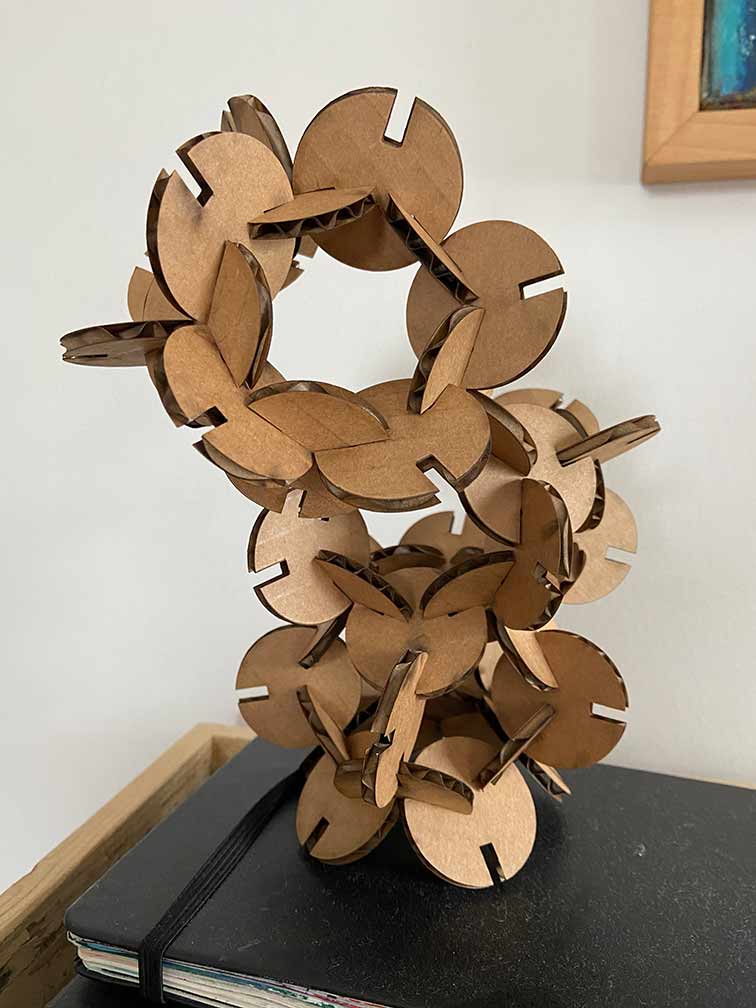
All connected!
4.3. Vinyl cut of a vector design.
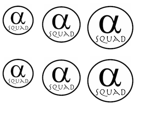
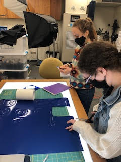
For this group project we designed our group team logo and made the dessign into vinyl stickers.
To create our logo we used the design program Affinity Publisher

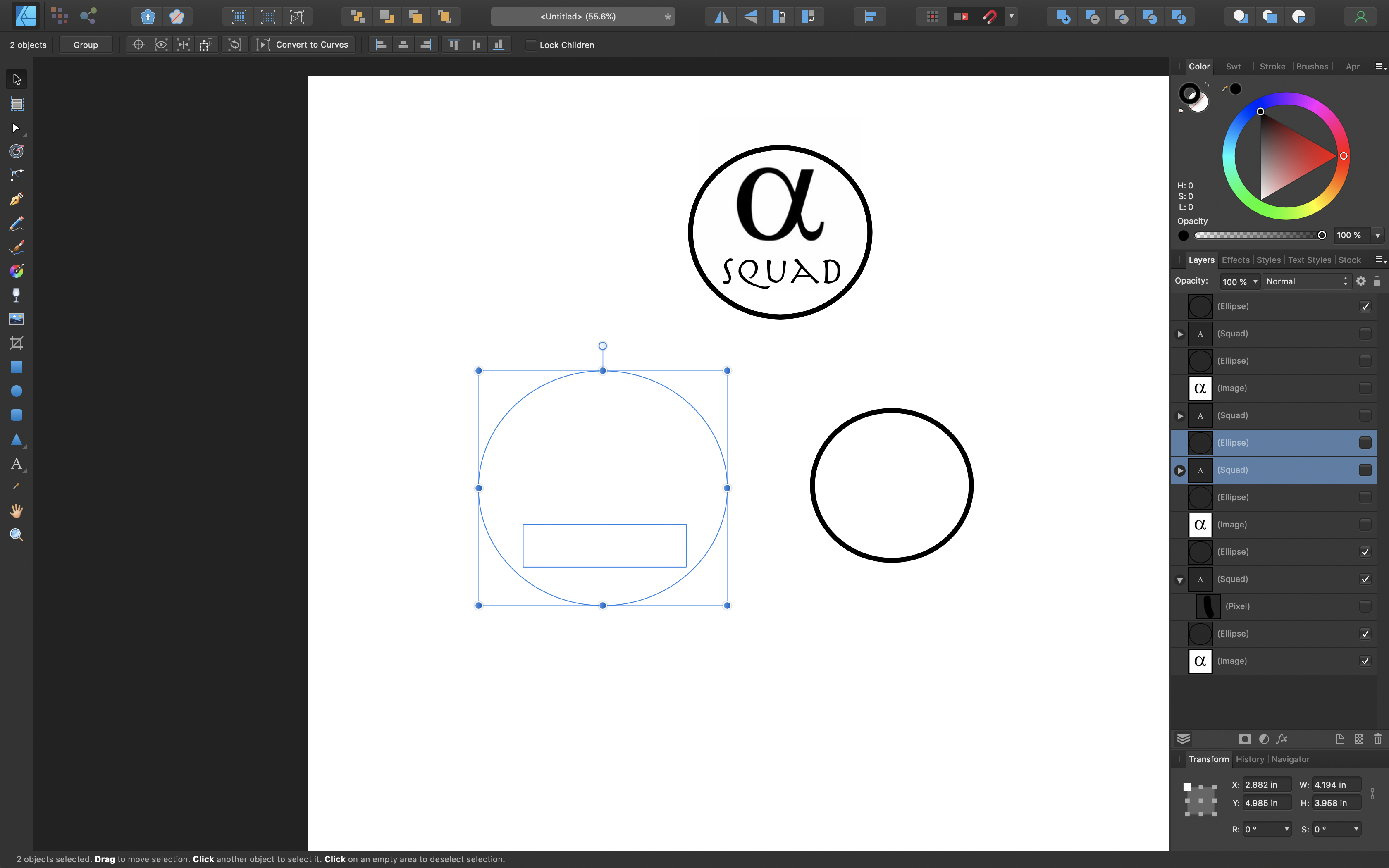
Here we are designing our logo in Affinity
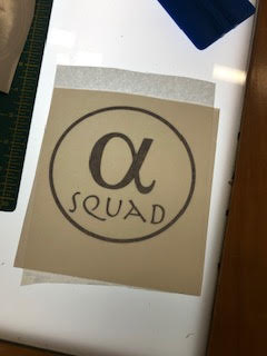
Then we uploaded our design to the program surecutsalot
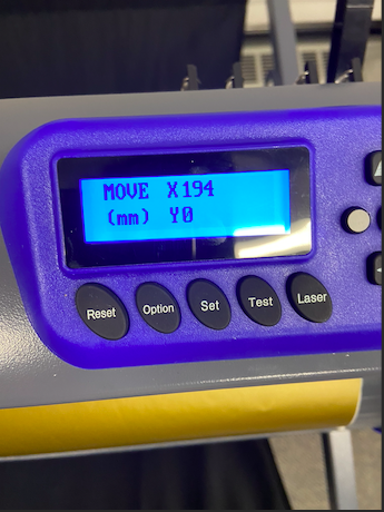
Then we reset the vinyl cutter settings to align our sticker vinyl paper in the correct location and set it to cut.
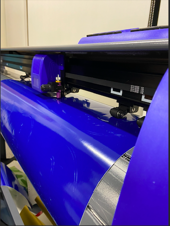
Here is the vinyl cutter in action creating our logo
Next we cut out our sicker vinyl by removing the access material that is not part of our logo design
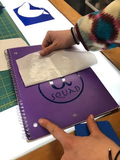
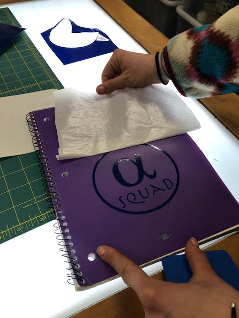
Then we adhere our vinyl design to adhesive tape and make sure to remove any air bubbles
Next we press our desgin and squeegee it to our desired surface, I decided to put mine on my class notebook. Lastly we peeled off the vinyl adhesive tape.
Final product!
Here is the link to my project files link here!