WEEK 13
- 1.- Introduction
- 2.- Teamwork
- 3.- Pinouts ATTiny44 - ATTiny1614 - ESP32:
- 4.- ESP32 Bluetooth:
- 5.- I2C Communications:
- 6.- HEC ATTINY 1614:
- 7.- My test ATTiny1614 master - ATTiny44 slave:
- 8.- My test with ESP32 and ATTINY44:
- 9.- Example with the three circuits: 1 master and two slaves:
- 10.- ESP32 web server. Using WiFi communication with ESP32:
- 11.- Experience and conclusions of the week 13:
- 12.- Files:
Networking and Communications:
Teamwork
Individual Assessment
Fab-Weeks
Are you looking for my assignments?
Links and notes
more information:
Week 13: Networking and Communications
1.- Introduction:
I am going to focus on the ESP32 because it has a built-in WiFi module and Bluetooth with Low Energy mode and Classic mode.
To do the tests, I am going to use the board that I created in the previous week using Bluetooth and WiFi. In addition, I will use the I2C communication to complete the Assessment, I will connect the ESP32 as a master and I will use my HelloBoard with an ATTiny44 and another board that I am going to design with an ATT1614 to connect as slaves.
Week Journal:

2.- Teamwork
If you want to know the group assessment of this week, click on the image of SediCupCt.

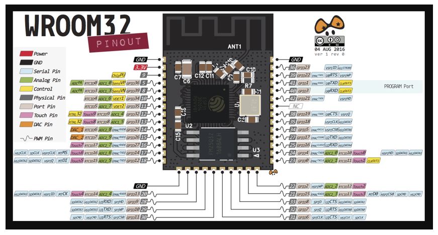
3.- Pinouts ATTiny44 - ATTiny1614 - ESP32:
Next I am going to put the captures for the pinouts of the microcontrollers that I am going to use.
It is very useful to know which pins are for programming, which are for I2C communication and which I will use to connect the inputs and outputs.
ATTiny44:

ATTiny1614:

ESP32:
4.- ESP32 Bluetooth:
For the first test that I am going to carry out with the ESP32, I need to install an application on the Smartphone. With this application I will connect the Bluetooth of the ESP32 with the Bluetooth of the Smartphone, intercommunicating both devices.
The application is: Serial Bluetooth Terminal.
https://play.google.com/store/apps/details?id=de.kai_morich.serial_bluetooth_terminal&hl=en

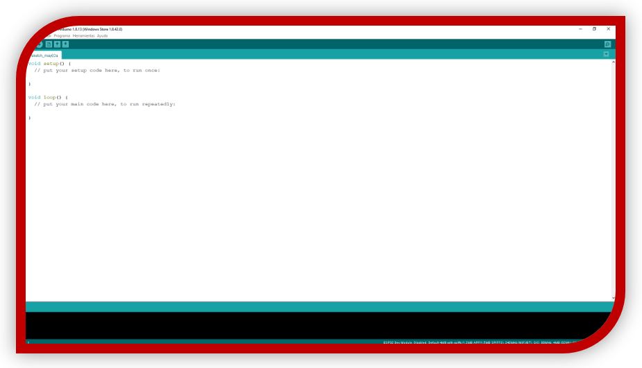
Once the application is installed on the Smartphone, I start the Arduino IDE to program my ESP32.
■ Note: before using the Arduino IDE, you must install the ESP32 plug-in and the drivers for the microcontroller, if they are not installed on the computer used to program. In my case, I installed everything in the previous weeks. Week10: Inpunt Devices -> point 6: Programming
So, I can use the ESP32 Bluetooth example to test it. To do this: File -> Examples -> BluetoothSerial -> SerialtoSerialBT.
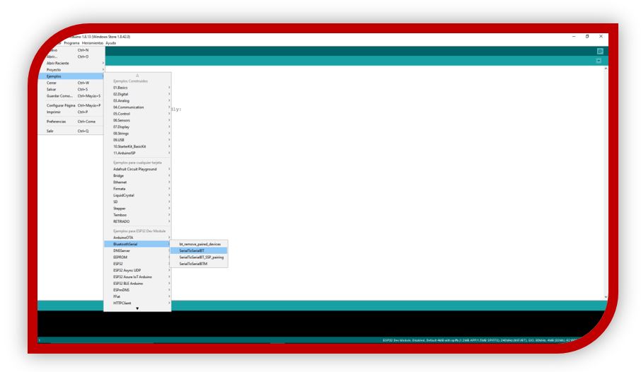
The sample code for serial communications with Bluetooth opens.
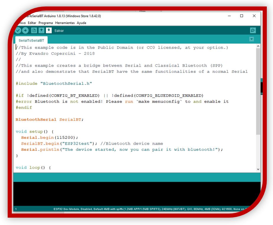
This code is responsible for establishing bidirectional communication between two computers. It begins with the declaration of the Bluetooth library "BluetoothSerial.h" that contains the functions necessary to establish communications through this type of channel.
The next thing the code does is check that Bluetooth is enabled correctly and creates an instance for serial communication.
From the configuration, you can set the communication speed.
Then, with SerialBT.write () and Serial.read () the data is sent and read through the serial port, if available.
SerialBT.write (): takes care of sending the data using Bluetooth.
if (Serial.available()) {
SerialBT.write(Serial.read());
}
With this condition, it checks if it is receiving data on the serial port, if it receives data, it sends it via Bluetooth.
if (SerialBT.available()) {
Serial.write(SerialBT.read());
}
With this other condition, it is checked if there is data to read through the serial port, if there is data, it writes it through the terminal.
TESTING:
I connect the ESP32 and program it:
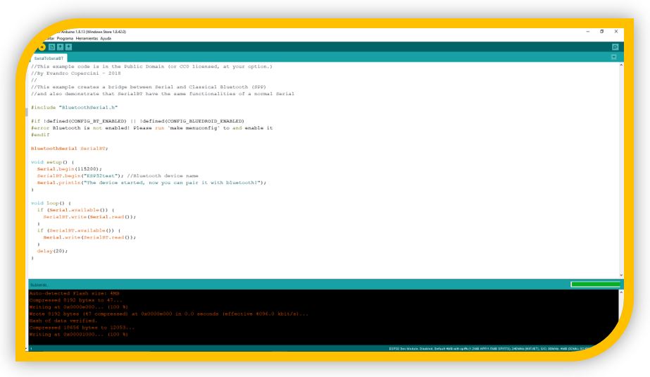
Once loaded, I open the Arduino IDE serial monitor, configuring it at the speed that I have indicated, of 115200 and I press the reset button on my ESP32 board:
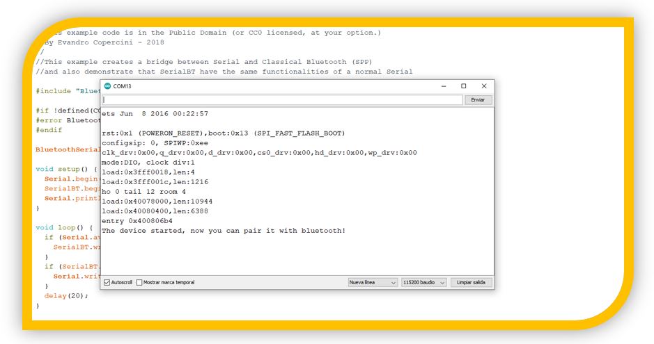
By the serial monitor, it tells me that the device is now ready to pair!
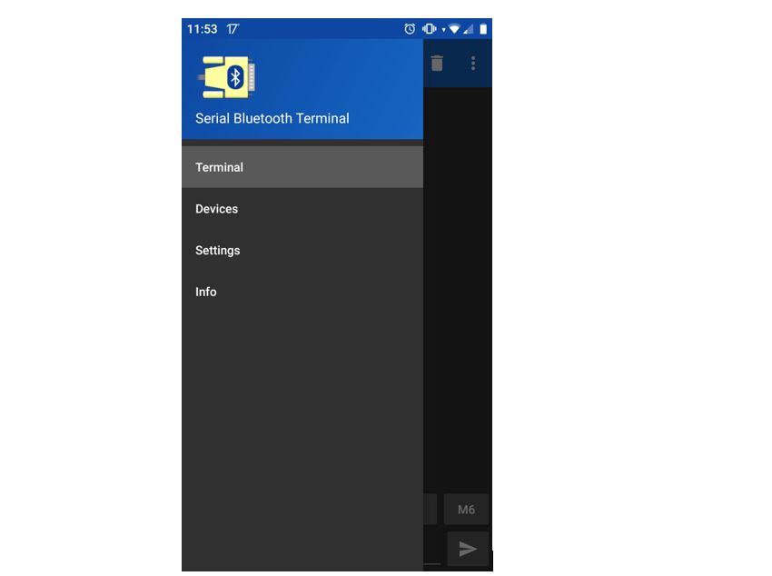
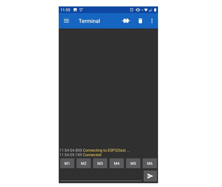
Now, I open the “Serial Bluetooth Terminal” application on the Smartphone (with the Smartphone's Bluetooth enabled). Menu -> Devices
I connect to the ESP32test.
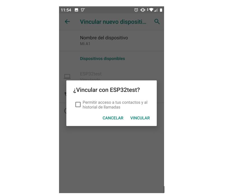
■ NOTE: It detected the device without any problems. In case it is not detected, press the reset button again and search for devices with the Smartphone.
In the Smartphone terminal, it tells me that it is connected to my ESP32:
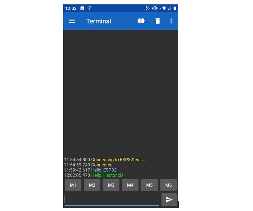
I try to send a message:

My ESP32 board received it!

Now I try to respond from ESP32 with the Arduino IDE terminal:

The sent message is not displayed from the Arduino IDE serial monitor, but I received it instantly on my Smartphone.
TEST FOR SENSOR READING
Head part:
1. Include the libraries "BluetoothSerial.h" and "OneWire.h"
2. Create a SerialBT instance, for serial communication.
3. Indicate the pin for the sensor, it must be a GPIO (const int oneWireBus = 32;)
4. Create instance to connect between devices (OneWire oneWire (oneWireBus);
5. Variable (message) to store the readings (String message = "";
6. IncomingChar variable to store messages received through Bluetooth Serial (char incomingChar;)
7. Variable for sensor reading (String sensorString = “”;)
8. Variables to take sensor readings every 10 seconds (unsigned long previousMillis = 0; last published temperature and const long interval = 10000 with the time interval for the sensor reading)
Main part:
1. In setup start ESP32 as Bluetooth (SerialBT.begin (“ESP32”))
2. In the loop everything necessary for sending and receiving sensor readings.
unsigned long currentMillis = Millis ();
if (currentMillis - previousMillis> = intervak) {
previousMillis = currenMillis;
sensor.lectureSensor (); // do the reading like the previous week
sensorString = "";} // readings
3. Send the reading via Bluetooth (SerialBT.printIn (sensorString);
4. Read incoming messages, checking if there is data via Bluetooth, if there is they are saved in the incomingChar variable.
if (SerialBT.available ()) {
char incomingChar = SerialBT.read ();
if (incomingChar! = '\ n') {
message + = String (incomingChar);
}
else {
message = "";
}
Serial.write (incomingChar);
}
5.- I2C Communications:
The ESP32 has I2C protocol that allows its use to act as a master or as a slave.
I2C means Inter Integrated Circuit (I-Squared-C). It is a synchronous multi-slave communication system. There may be:
• Multiple slaves to one master. • Multiple masters controlling the same slave.
The ESP32 I2C interfaces support:
■ Standard mode (100 Kbit / s).
■ Fast mode (400 Kbit / s).
■ Up to 5 MHz, but limited by SDA pull-up force.
■ 7-bit / 10-bit addressing mode.
■ Dual addressing mode. Users can program command registers to control I²C interfaces for more flexibility.
In the communication protocol with I2C, two cables are used to share information.
■ One is used for SCL or SCK clock signal.
■ The other is used to send and receive SDA or SDI data.
** NOTE: These lines are active low, so resistors must be connected. Typical values are 4.7 k Omh for 5V devices and 2.4 k Ohm for 3.3V devices. (In general, most of the sensors that come in modules, already have this type of resistors connected, otherwise, they would have to be added).
CONNECTION - ESP32:
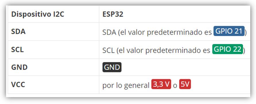
To connect an I2C device to an ESP32 you have to connect the GNDs between them, the SDA pins with SDA and the SCL pins with SCL and a VCC source, usually 3.3V or 5V.
For the ESP32 using Arduino IDE, the default pins in the following image are used, although others can be configured as well:
With I2C communication, each slave on the bus has its own address, a hexadecimal number that allows the ESP32 to communicate with each device.
The I2C address can be usually found on the component’s datasheet. However, if it is difficult to find out, you may need to run an I2C scanner sketch to find out the I2C address. An example: by Arduino serial monitor, hexadecimal address is displayed.
#include
void setup() {
Wire.begin();
Serial.begin(115200);
Serial.println("\nI2C Scanner");
}
void loop() {
byte error, address;
int nDevices;
Serial.println("Scanning...");
nDevices = 0;
for(address = 1; address < 127; address++ ) {
Wire.beginTransmission(address);
error = Wire.endTransmission();
if (error == 0) {
Serial.print("I2C device found at address 0x");
if (address<16) {
Serial.print("0");
}
Serial.println(address,HEX);
nDevices++;
}
else if (error==4) {
Serial.print("Unknow error at address 0x");
if (address<16) {
Serial.print("0");
}
Serial.println(address,HEX);
}
}
if (nDevices == 0) {
Serial.println("No I2C devices found\n");
}
else {
Serial.println("done\n");
}
delay(5000);
}
■ NOTE: when using ESP32 with Arduino IDE, it is convenient to use Wire.h library to establish I2C communication. (Wire.begin (I2C_SDA, I2C_SCL). It will only be necessary to configure the GPIOs to be used.
Ways to connect devices:
Same bus and different addresses:
Peripherals are connected to the ESP32 SCL and SDA lines and each peripheral is referred to in the code by its address.
Multiple I2C devices with the same address:
The I2C address of the device must be changed, some boards allow using a "bridge" resistor.
Or, in the case that it cannot be done directly, you have to use a multiplexer. An example is the TCA9548A which allows up to 8 devices to communicate.
I2C with ESP32 using two I2C interfaces:
In this way you can use two I2C buses each to connect two different devices, usually the first with the default parameters and the second with the configured ones. To use the two I2C interfaces with ESP32, you have to create two instances, TwoWire:
TwoWire I2Cone = TwoWire (0);
TwoWire I2Ctwo = TwoWire (1);
Then start communication on the desired pins
Void setup () {
I2Cone.begin (SDA_1, SCL_1, freq1);
I2Ctwo.begin (SDA_2, SCL_2, frec2
}
Then use "Wire.h" to interact with the I2C.
■ Note: an alternative is to use the predefined Wire () and Wire1 (). With Wire.begin (); I2C communication is created with the first I2C bus using the default pins and the default frequency (100000Hz). For the Wire1.begin (); you must pass the desired SDA and SCL pins and the frequency:
Void setup () {
Wire.begin (); / predefined
Wire1.begin (SDA_2, SCL_2, freq);
}
6.- HEC ATTINY 1614:
The plate that I have created in this assignment, is the following:

I have freed all the input and output pins, so the board can be used as a trainer and I can practice connecting other boards, sensors, actuators, etc.

this is the electronic board for milling.

this is the cut of the electronic board


After manufacturing the board, I had to install the Arduino libraries for this microprocessor.
Install board manager in Arduino IDE

It is important to have the FTDI-USB connected and choose the "Serial Port and 4.7k (pyupdi style) programmer.
To test the board, I upload the code for the hello board:
For the I2C with ATtiny I take the TinyWireM.h library, although I will try first with the Wire, but as for the ATTiny44 I need the TinyWireS to make it a slave, in case I have a conflict with the Wire.h I download the WireM.
https://github.com/adafruit/TinyWireM
*** NOTE: for the ATTiny1614 definitely use the Wire.h library. For the ATTiny44 use the library TinyWireM.h and TinyWireS.h.
7.- My test ATTiny1614 master - ATTiny44 slave:
In this example, I have used the HEC-ATTINY1614 board as a master, it is responsible for sending a signal to the HelloATTiny44 that I did in the week before, and the ATTiny44 when receiving the signal lights, a blue led for 3 seconds.
Also, I have opened the Arduino serial monitor to show how the slave board is waiting and how the signal is activated when I press the button on the master board.
In this example, the ATtiny1614 microcontroller electronics board is used as the master to communicate with an excavated electronics board with an ATtiny 44 microcontroller.

Within the code, it will be necessary to include the Wire and TinyWire libraries (less heavy version) for I2C communications and define the address for the electronics of the slave board, in this case the ATtiny44 with the address 0x9.
The SCL and SDA pins must also be declared for each microcontroller, which with another pin GND and VCC will form the I2C communication bus. (pin 6 - SDA and pin 7 - SCL for the ATtiny1614 and pin 6 - SDA and pin 4 - SCL for the ATtiny44).
With these configurations, within the loop, in programming, the master ATtiny1614 is in charge of reading the button for when it is pressed, activating the communications functions and sending the activation to the slave ATtiny44 board so that it executes its loop with the activation. of the led.
The operation is in the video:
8.- My test with ESP32 and ATTINY44:
This example that I have done is similar to the previous one. But as a master board I have used the HEC-TRAINER-ESP32. To simulate the button, I have attached a cable to gnd and another to the control pin, and by hand one both when I want to send the signal (as seen in the video).
The slave ATTiny44 is waiting for this signal and when it receives it, it activates a green led for a few seconds.
This example can be watched in the video:
9.- Example with the three circuits: 1 master and two slaves:
For this example, I used 3 electronic boards. The master board with the ESP32 and the slaves with the Attiny44 and another with the Atiny1614.
The master electronic board is that of the ESP32 microcontroller, which uses the I2C to communicate with the other boards using pins 21 - SDA, 22 - SCL, GND and VCC.
For slave electronic cards it is necessary to define an address for the identification of each one of them and to know with which electronic card it is communicating. In this example, the ATtiny44 electronic board has the address 0x9 and the ATtiny1614 electronic board has the 0x8 address.
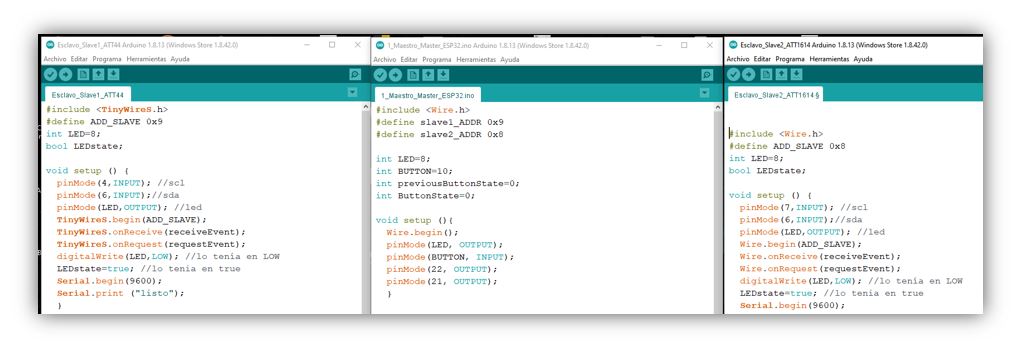
The two slave electronic boards are that of the ATtiny44 microcontroller that uses pin 4 - SCL, pin 6 - SDA, GND and VCC for the I2C bus and that of the ATtiny1614 microcontroller with pins 6 - SDA, 7 - SCL, GND and VCC for I2C communication between electronic boards.
In the programming code for each of the slave electronic boards (ATtiny44 and ATtiny1614), it is necessary to indicate the same address (0x9 and 0x8) that was assigned for each of them in the master code (ESP32).

In the loop, the ESP32 master is in charge of reading the button, when it detects that it is pressed, it calls the communication functions to transmit to slave1 and slave2 that the button has been activated and that each of them must begin to perform their task, that of turning on each one their led for a certain time when it corresponds to them.
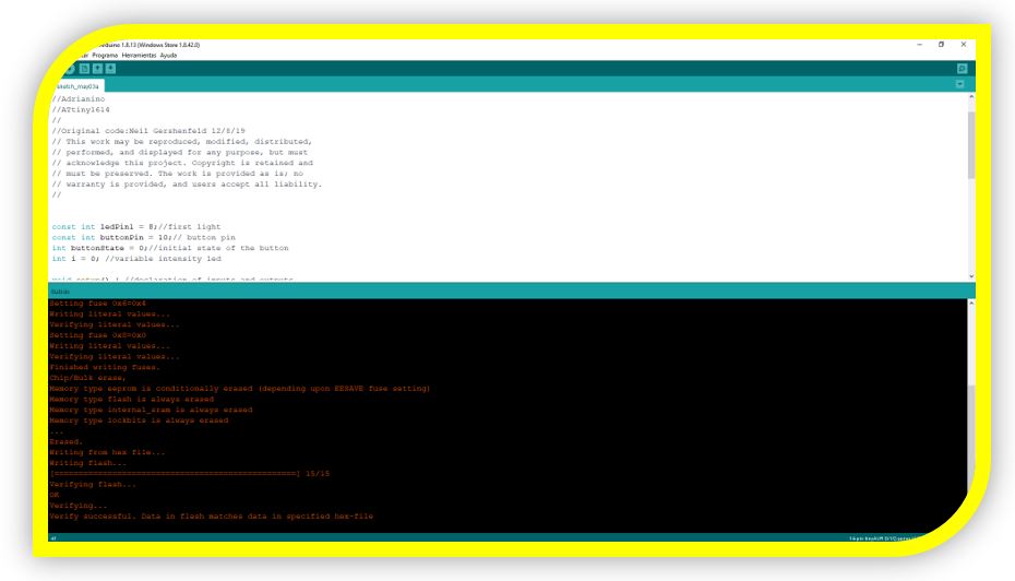
Also, to test a new one, I used an "Adrianino" plate to show that I can use other plates, apart from mine.

Then load a master code that makes through a button, connected to the master board, send a signal to the board with the Attiny44 that turns on a led for 3 seconds and another signal to the Attiny1614 that turns on another led for 1 second.
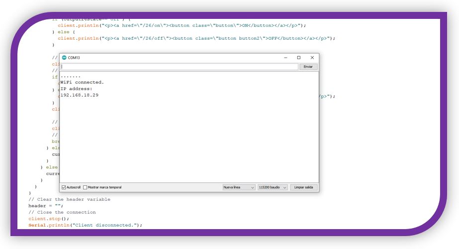
10.- ESP32 web server. Using WiFi communication with ESP32:
With this example I am going to connect my ESP32 to create a web server to control two LEDs.
■ LEDs will go to GPIO26 and GPIO27
■ To access the server, just use the IP from a browser on the local network


I connect the LEDs:

I upload the program:

From Aruino IDE I open the serial monitor to know the IP with which to connect from the browser:
Connection video:
11.- Experience and conclusions of the week 13
Difficult week. Communication between the electronic boards was something new for me.
I had problems to connect between them, I did not arrive at the Regional Review with results. I commented on it and they gave me advice.
With the help of my instructor, I was able to communicate the electronic boards successfully.
I also tried some WiFi communication with the ESP32 module to test that it works and with the possibility to use it in the final project.
With the WiFi module, I had no problems it worked very well.
“What went wrong”: I had quite a few problems with communication between plates, being a new topic for me.
“What went well”: The new board that I made with the ATtiny 1614 worked without problems.
“What will you do differently next time”: I would try something with the new SAM microcontrollers and maybe interconnectivity with WiFi between several boards.
12.- FILES
3 codes ESP32 master Attiny1614 & 44 slavesBluetooth sample
code master slave sample 1
code master slave sample 2
Web Server ESP32
MyHelloBoard HEC-TRAINER-ESP32 HEC-ATTINY-1614