WEEK 12
Fab-Weeks
Are you looking for my assignments?
Links and notes
more information:
Week 12: Output Devices
1.-Introduction:
This is a week to test the output devices with the microcontrollers. In my case, I am going to test the NEMA17 stepper motors, which are the ones I am going to use for the dispenser of my final project.
2.-Teamwork
If you want to know the group assessment of this week, click on the image of SediCupCt.

3.- First steps:
To work with the design of the electronic board I am going to use Eagle. So the first thing I have to do is add the libraries with the electronic components that I need and don't have yet.
Once the missing components have been identified and the libraries searched, they just have to be installed in the correct location for Eagle to detect them. Below I will indicate the libraries that I have used.
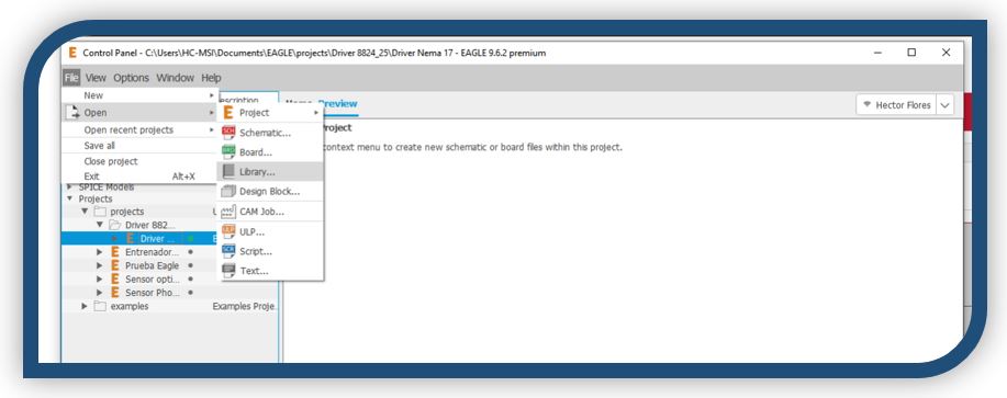
To do this, File -> New -> Library
Execute script:
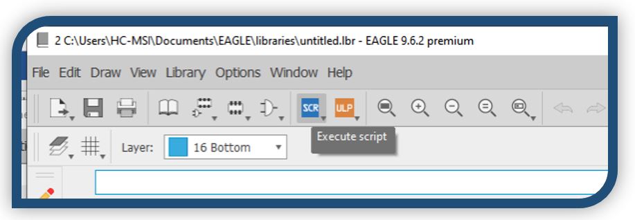
In the next window, search for the library:

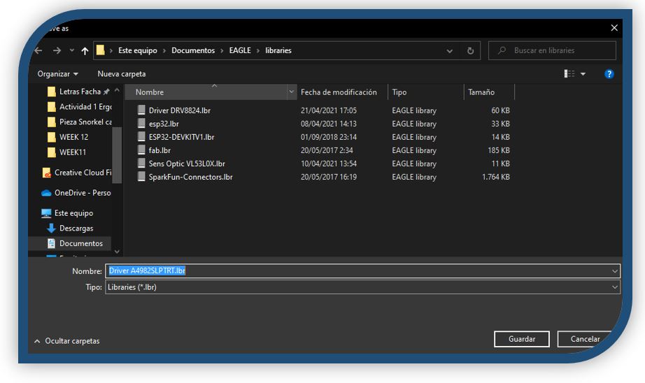
For example, in the following case, I have opened the A4982 SLPTRT driver library

Now click to save, and it will be added to the Eagle library list, which we can open from the Library Manager.
4.- Using the DRV8825 driver:
As I have mentioned, the first thing I need is the driver library to be able to work on the design of the electronic board.
From the next page I have access to driver information and in many cases to the libraries with the design for each component.
To download the Eagle library for the DRV8825, I used the following link:
As a useful source to design my board for the driver, I will rely on:
https://www.pololu.com/file/0J603/drv8824-drv8825-stepper-motor-driver-carrier-schematic-diagram.pdf
and the trimer that I am going to use is:
https://www.digikey.es/product-detail/es/tt-electronics-bi/23BR10KLFTR/987-1014-2-ND/2408592
with its corresponding library:
and its datasheet
https://www.ttelectronics.com/TTElectronics/media/ProductFiles/Trimmers/Datasheets/23.pdf
So, I install the Eagle library and start designing the schematic:
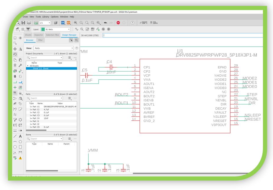
The complete schematic is:
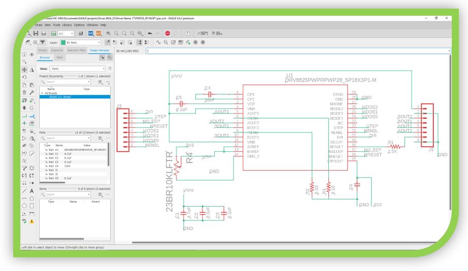
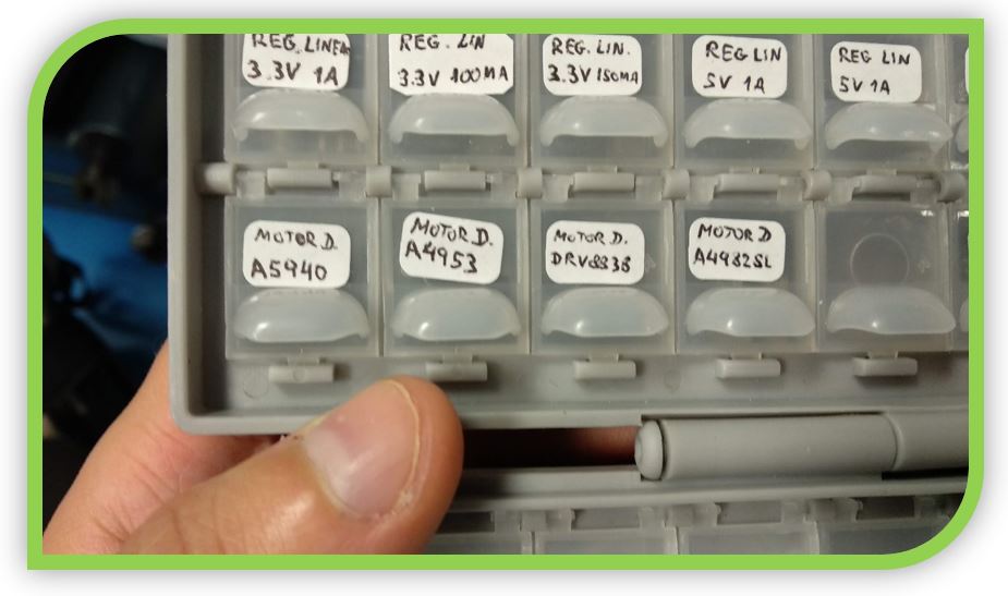
As a drawback, I have to update the design to the A4982 SLPTR-T driver because we have the DRV8838, which is for a single DC motor, not a stepper and not the driver, not the DRV8825 with which I have designed. We only have the DRV8825 with the prefabricated module, which is the one we use in the week of creating a machine.
** I'll keep it in case I need it in the future, since I'm not going to use this driver.
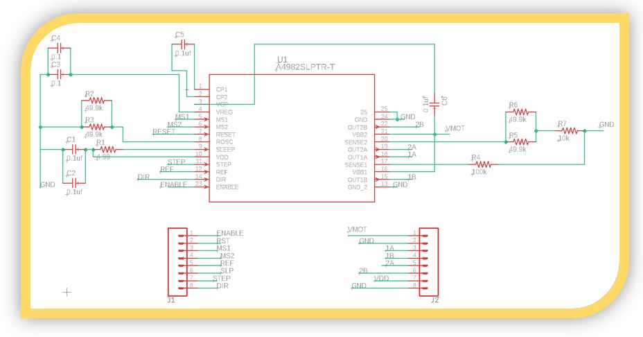
5.- Using Driver A4982 SLPTR-T:
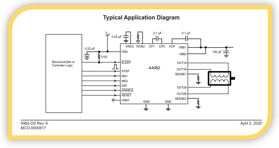
As in the previous case, I look for information about the driver:
https://www.digikey.es/product-detail/es/allegro-microsystems/A4982SLPTR-T/620-1352-2-ND/2295512
I download your library for Eagle:
and I'm looking for a schematic to help me design the board:
Option 1:
https://beta.ivc.no/wiki/index.php/File:MakerBot_Replicator_HoekDrive17_A4982_schematic.png
Option 2:
http://fab.academany.org/2020/labs/newcairo/students/abdelrahman-elshakankery/machinedesign.html
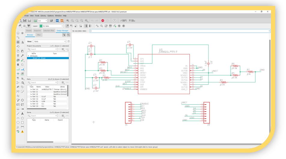
So, I draw the new schematic:
Now I can create the DRC for this schematic. But when loading the components to route, I realize that the package is too small to solder, I will have problems, so I decide to move on to using the A4953 driver.
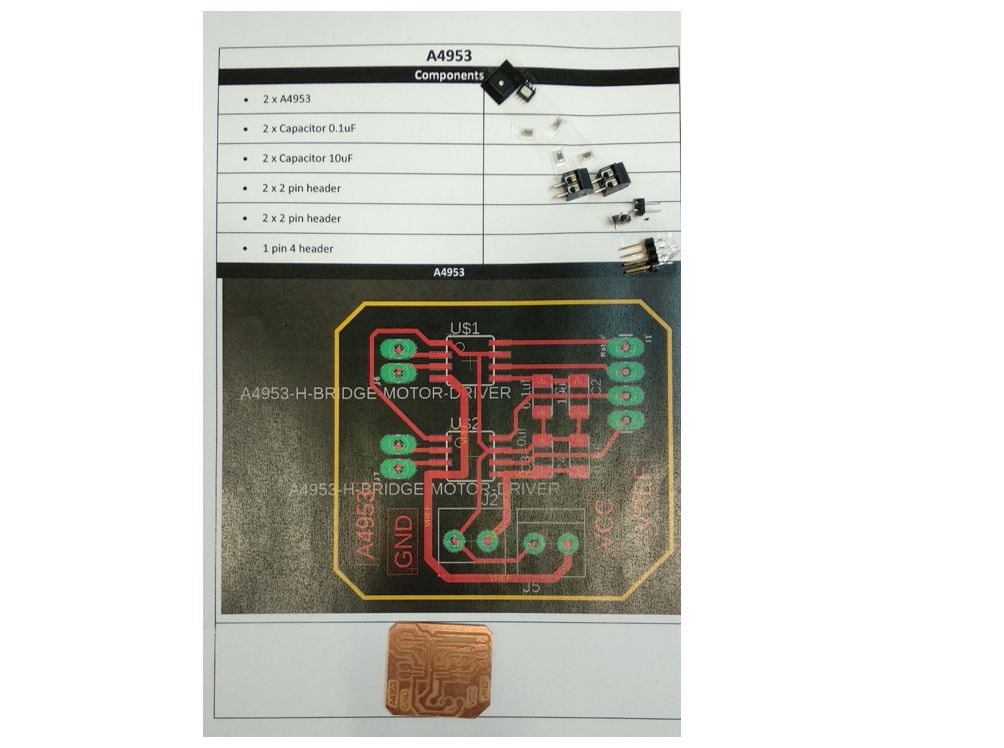
6.- Using the A4953 driver:
Again, I proceed with the consultation of the information:
https://www.alldatasheet.com/datasheet-pdf/pdf/480156/ALLEGRO/A4953.html
In this case, I don't download the library because this component is included in the fab library, from the FabAcademy.
But in case it was necessary:
https://www.snapeda.com/parts/A4953ELJTR-T/Allegro%20MicroSystems%20LLC/view-part/?ref=digikey
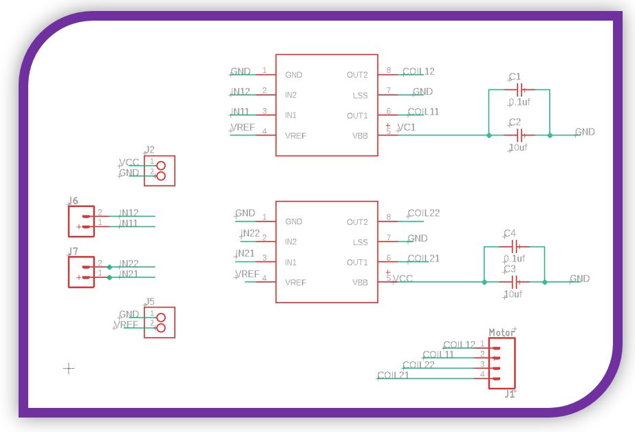
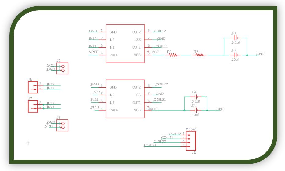
So I draw my new schematic:

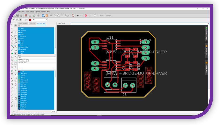
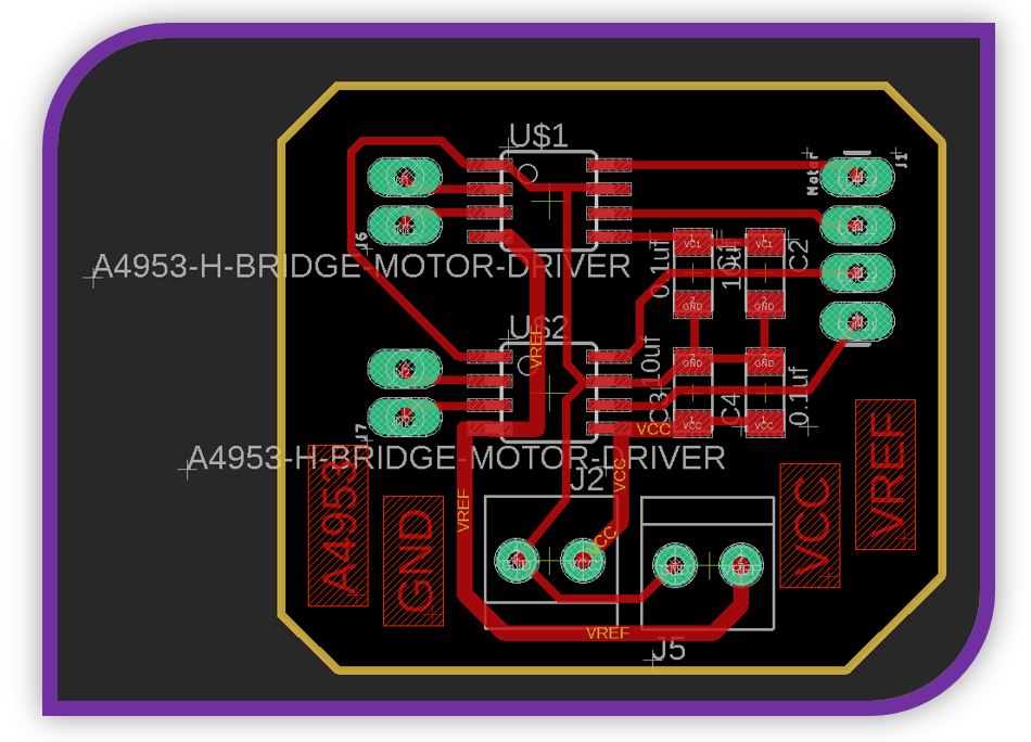
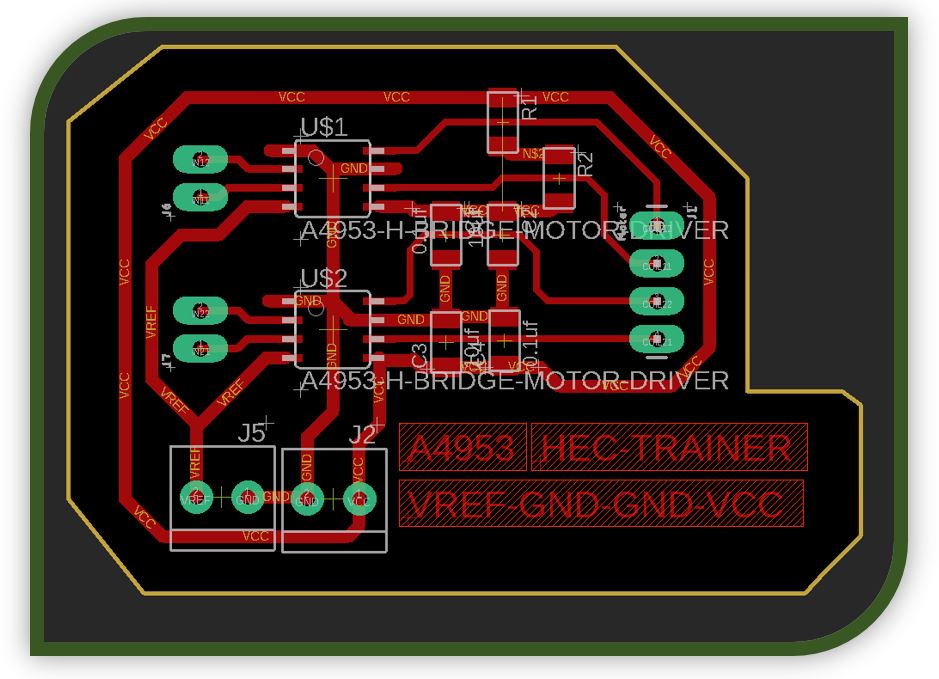
And now if I draw the DRC:
To dissipate better, I am going to increase the GND trace.
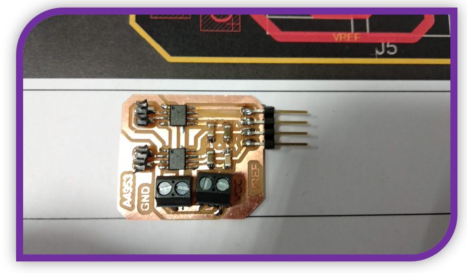
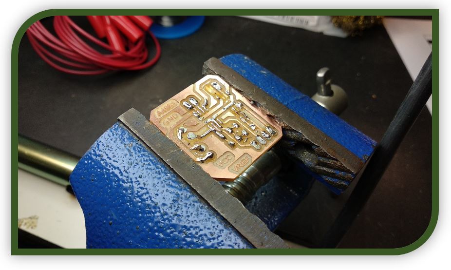
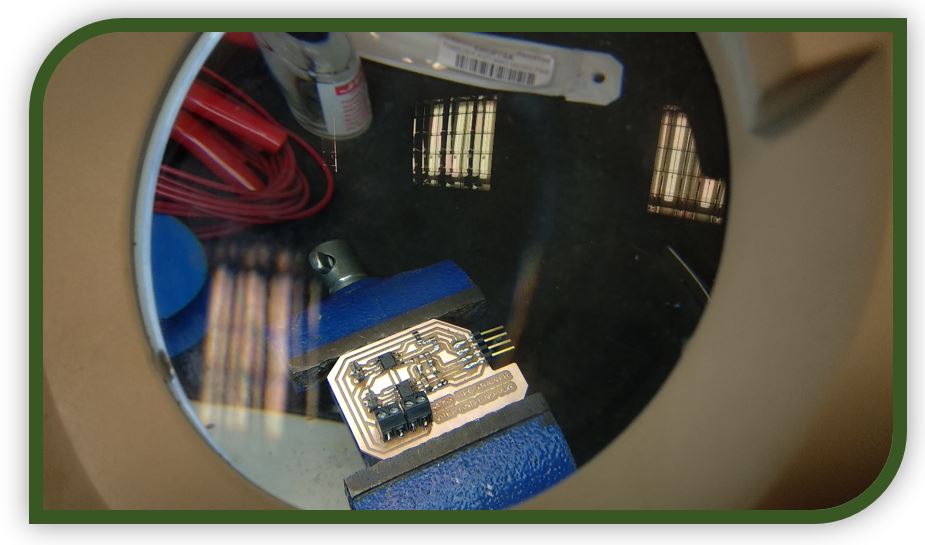
I weld the components of the electronic board:
7.-Test number1:
I tried a test code that used pins 8, 9, 10, 11, but it didn't work for me, based on the pin out of the ESP32 there should be no drawbacks, but the stepper motor wasn't moving.
The code I used was the same one used by Neil.
I tried the example of a helloboard, with the same pins assigned, but it didn't work either.
Just in case, check the continuity of the electronic circuit leads with the multimeter.
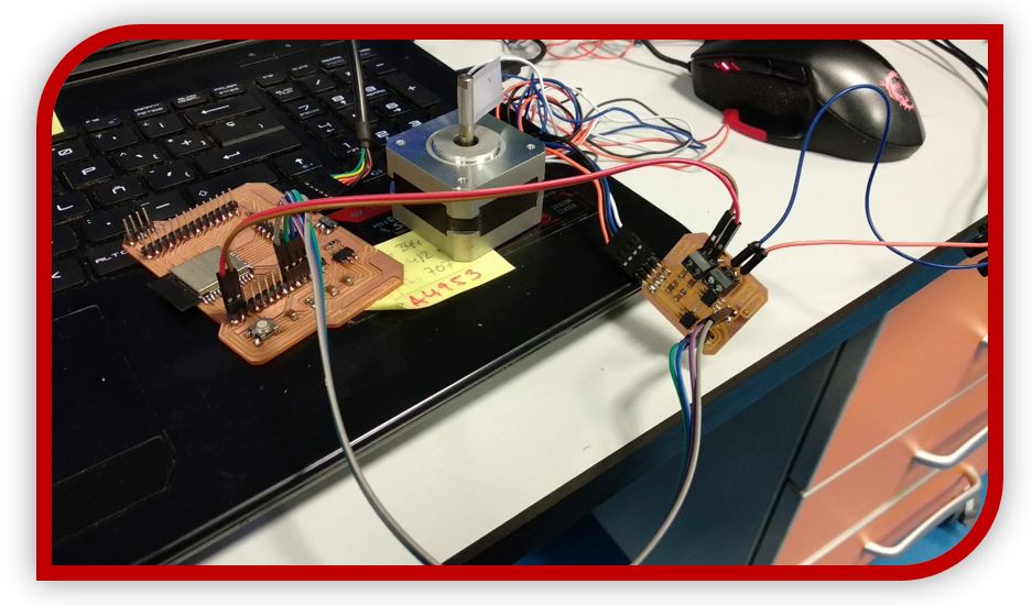
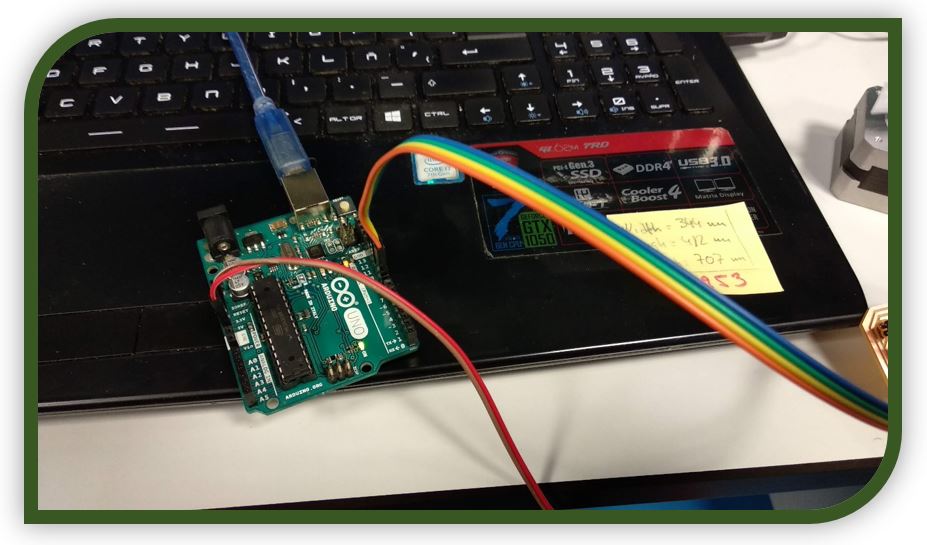
After reviewing the electronic board, it occurred to me to test the driver that I had designed this week with an Arduino UNO (since it is usually compatible with a lot of things).
With testing the Arduino UNO, the motor spun perfectly with both examples.
8.-Test number2:
Since it worked for me on Arduido UNO and the HECT-TRAINER-ESP32 board worked for me in inputs week, I started looking for more information about the ESP32 and its use with stepper motors.
■ Review with the Regional Review:
Presenting my progress in the regional Review, I showed the problems that I have had and reviewing the final driver model, they realized that in Driver 1 A4953 I was missing a power line. I checked the schematic and the label was wrongly placed on the power supply of that driver.
This schematic is the corrected version:
Now with the testing of this new board, when programming the microcontroller it has worked correctly:
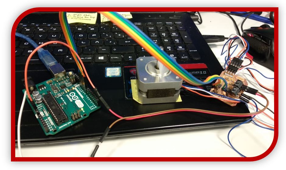
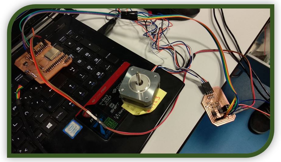
Try with Arduino UNO:
Test with ESP32:
9.-Test control stepper:
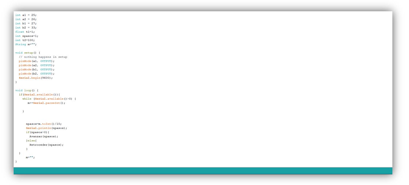
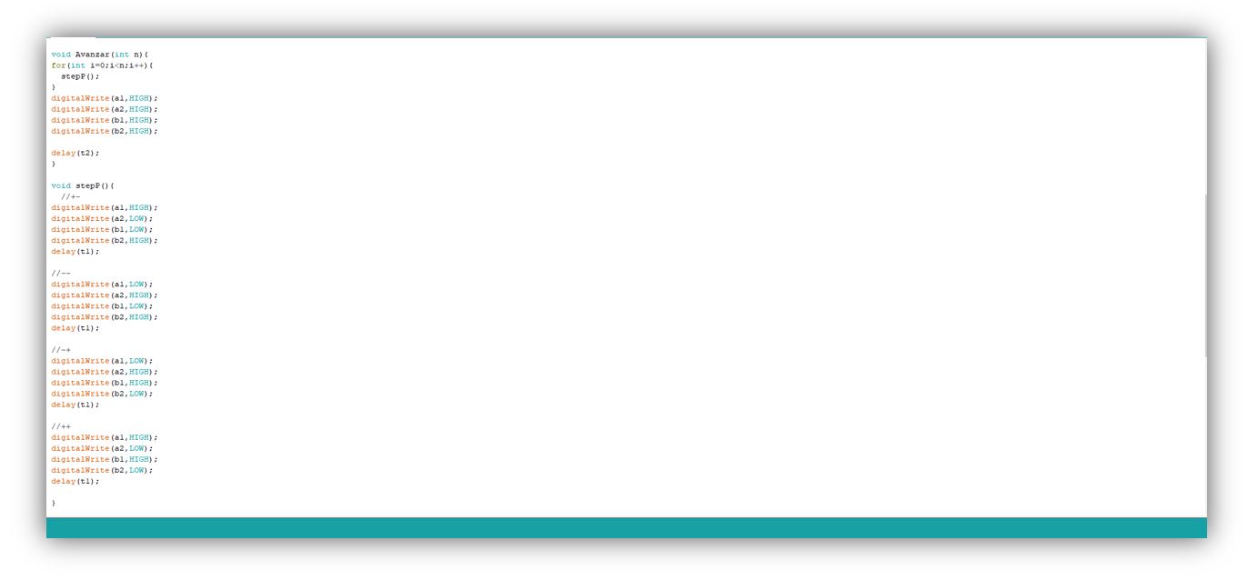
After trying the basic examples with the code to go one step back and one step back, or go step by step in one direction or another, in a loop. I'm going to use a code for me to indicate the number of steps that I want the motor to give, indicating the value with the Arduino serial port.
In this example I declare the variables for each input of the bovine, a variable for counter steps, a waiting time and another variable to store the steps that we want to introduce to control the rotation of the motor.
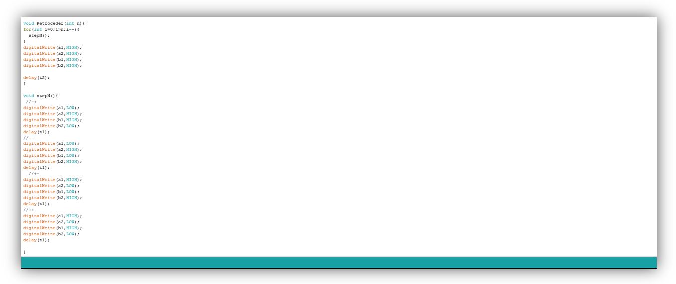
In the loop, what it does is read the number of steps that we have entered through the Arduino serial port. If it is a positive value, what it does is call a function to advance the number of steps indicated by the serial port and if the value is negative, it calls a function to go back the number of steps entered in the serial port.
The Advance function, upon receiving a positive value, begins to activate the different motor coils at low and high levels with the sequence ordered to create movement in one direction, in this case the one considered advance.
The Reverse function, upon receiving a negative value, begins to activate the different motor coils at low and high levels with the sequence ordered to create movement in one direction, in this case the one considered to go back, opposite to the previous one of Forward.
the result should work as follows
10.-My experience and conclusions from week 12:
This week has been a brain-buster. All because I did not realize with the fault of the track that it was wrong. After the Reginal Review, where they helped me, I redesigned the board for the driver and everything worked the first time.
Sometimes exposing bad results is the solution!
At first it was tough for the number of times I tried and it didn't work, but when it started to work well with the new design, the week became more fun.
“What went wrong”: I started off with a slightly bad choice for stepper motor drivers, but it was helpful for me to learn a little about each possible driver that can be used. Also with the first board, even though it worked on Arduino, I forgot to close an outer Vcc track. When redesigning the board worked with ESP32 and with Arduino.
“What went well”: Learning about drivers and testing when I made the final electronic board.
“What will you do differently next time”: I would try another finer soldering technique, to be able to solder the very small driver encapsulations.
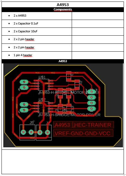
11.- FILES
All code files using in this weekAll Eagle files using in this week